EP1357073A1 - Elevator main rope elongation sensor - Google Patents
Elevator main rope elongation sensor Download PDFInfo
- Publication number
- EP1357073A1 EP1357073A1 EP00979984A EP00979984A EP1357073A1 EP 1357073 A1 EP1357073 A1 EP 1357073A1 EP 00979984 A EP00979984 A EP 00979984A EP 00979984 A EP00979984 A EP 00979984A EP 1357073 A1 EP1357073 A1 EP 1357073A1
- Authority
- EP
- European Patent Office
- Prior art keywords
- main rope
- detector apparatus
- electrical resistance
- determining means
- electrically
- Prior art date
- Legal status (The legal status is an assumption and is not a legal conclusion. Google has not performed a legal analysis and makes no representation as to the accuracy of the status listed.)
- Withdrawn
Links
Images


Classifications
-
- D—TEXTILES; PAPER
- D07—ROPES; CABLES OTHER THAN ELECTRIC
- D07B—ROPES OR CABLES IN GENERAL
- D07B1/00—Constructional features of ropes or cables
- D07B1/14—Ropes or cables with incorporated auxiliary elements, e.g. for marking, extending throughout the length of the rope or cable
- D07B1/145—Ropes or cables with incorporated auxiliary elements, e.g. for marking, extending throughout the length of the rope or cable comprising elements for indicating or detecting the rope or cable status
-
- B—PERFORMING OPERATIONS; TRANSPORTING
- B66—HOISTING; LIFTING; HAULING
- B66B—ELEVATORS; ESCALATORS OR MOVING WALKWAYS
- B66B5/00—Applications of checking, fault-correcting, or safety devices in elevators
- B66B5/0006—Monitoring devices or performance analysers
- B66B5/0037—Performance analysers
-
- B—PERFORMING OPERATIONS; TRANSPORTING
- B66—HOISTING; LIFTING; HAULING
- B66B—ELEVATORS; ESCALATORS OR MOVING WALKWAYS
- B66B7/00—Other common features of elevators
- B66B7/06—Arrangements of ropes or cables
- B66B7/10—Arrangements of ropes or cables for equalising rope or cable tension
-
- B—PERFORMING OPERATIONS; TRANSPORTING
- B66—HOISTING; LIFTING; HAULING
- B66B—ELEVATORS; ESCALATORS OR MOVING WALKWAYS
- B66B7/00—Other common features of elevators
- B66B7/12—Checking, lubricating, or cleaning means for ropes, cables or guides
- B66B7/1207—Checking means
- B66B7/1215—Checking means specially adapted for ropes or cables
- B66B7/1223—Checking means specially adapted for ropes or cables by analysing electric variables
-
- D—TEXTILES; PAPER
- D07—ROPES; CABLES OTHER THAN ELECTRIC
- D07B—ROPES OR CABLES IN GENERAL
- D07B2301/00—Controls
- D07B2301/25—System input signals, e.g. set points
- D07B2301/259—Strain or elongation
-
- D—TEXTILES; PAPER
- D07—ROPES; CABLES OTHER THAN ELECTRIC
- D07B—ROPES OR CABLES IN GENERAL
- D07B2301/00—Controls
- D07B2301/55—Sensors
- D07B2301/5531—Sensors using electric means or elements
- D07B2301/554—Sensors using electric means or elements for measuring variable resistance
Definitions
- the present invention relates to an elevator main rope elongation detector apparatus disposed in an elevator in which a car is suspended inside a hoistway by a main rope made of a synthetic fiber rope, the elevator main rope elongation detector apparatus detecting elongation of the main rope.
- a car and a counterweight are suspended inside a hoistway by a main rope.
- a car buffer and a counterweight buffer are installed on a bottom portion of the hoistway.
- a clearance dimension between the counterweight and the counterweight buffer when the car is stopped at an uppermost floor is required to be constantly maintained at a specified value.
- the clearance dimension between the counterweight and the counterweight buffer is reduced by elongation of the main rope with the passage of time.
- the amount of elongation of the main rope is as much as twice that of a steel rope.
- the clearance dimension between the counterweight and the counterweight buffer is conventionally measured during routine inspection.
- one maintenance worker drives the elevator, and another maintenance worker enters a pit in the hoistway and performs the measurement. Consequently, two maintenance workers are required, reducing work efficiency.
- the present invention aims to solve the above problems and an object of the present invention is to provide an elevator main rope elongation detector apparatus enabling elongation of a main rope made of a synthetic fiber rope to be detected simply and efficiently.
- an elevator main rope elongation detector apparatus disposed in an elevator in which a car is suspended inside a hoistway by a main rope made of a synthetic fiber rope having a synthetic fiber strand and an electrically-conductive filament, the elevator main rope elongation detector apparatus detecting elongation of the main rope, wherein the elevator main rope elongation detector apparatus includes: an electrical resistance measuring apparatus for measuring electrical resistance in the electrically-conductive filament; a determining means for determining whether a measured value from the electrical resistance measuring apparatus is within a preset normal range; and a warning means for issuing a warning when the measured value is determined by the determining means to be outside the preset normal range.
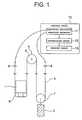
- Figure 1 is a structural diagram showing an elevator main rope elongation detector apparatus according to Embodiment 1 of the present invention.
- a car 1 and a counterweight 2 are suspended inside a hoistway by a main rope 3 made of a synthetic fiber rope.
- the main rope 3 includes: a plurality of synthetic fiber strands; and a plurality of carbon filaments functioning as electrically-conductive filaments integrated into at least some of these synthetic fiber strands over an entire length of each.
- An intermediate portion of the main rope 3 is wound around a drive sheave 5 of a driving machine 4 disposed in an upper portion of the hoistway.
- the car 1 and the counterweight 2 are raised and lowered by means of a driving force from the driving machine 4.
- a pair of car suspension sheaves 6 around which the main rope 3 is wound are disposed on a lower portion of the car 1.
- a counterweight suspension sheave 7 around which the main rope 3 is wound is disposed on an upper portion of the counterweight 2.
- First and second end portions of the main rope 3 are connected to respective rope stops 8 and 9 in the upper portion of the hoistway.
- An electrical resistance measuring apparatus 11 for measuring electrical resistance in the carbon filaments integrated into the main rope 3 is disposed in a control panel 10 for controlling elevator operation.
- the electrical resistance measuring apparatus 11 is connected to first and second end portions of the carbon filaments.
- a main rope elongation detector apparatus includes the electrical resistance measuring apparatus 11, the determining means 12, and the warning means 13.
- the electrical resistance of the carbon filaments in the main rope 3 is measured by the electrical resistance measuring apparatus 11 when necessary.
- the carbon filaments are disposed over the entire length of the main rope 3, stretching in a similar manner to the main rope 3 when age-related elongation arises in the main rope 3. In other words, when elongation arises in the main rope 3, the entire length of the carbon filaments elongates, reducing cross-sectional area and increasing electrical resistance.
- the measured value from the electrical resistance measuring apparatus 11 is monitored by the determining means 12 to determine whether there is any abnormality. If the measured value exceeds the preset normal range, an abnormality detection signal is sent to the warning means 13, whereby a warning is issued by the warning means 13. Then, any required action such as run-by adjustments or replacement of the main rope 3, etc., is undertaken by maintenance workers who receive the warning.
- a main rope elongation detector apparatus of this kind elongation of the main rope 3 can be detected simply and efficiently when necessary regardless of the position of the car 1. Furthermore, the elongation of the main rope 3 can be checked remotely and automatically, enabling reductions in costs required for maintenance inspections.
- Figure 2 is a structural diagram showing part of an elevator main rope elongation detector apparatus according to Embodiment 2 of the present invention.
- the main rope 3 made of a synthetic fiber rope includes: a plurality of synthetic fiber strands 31 composed of an aramid resin or the like; and a plurality of carbon filaments 32 functioning as electrically-conductive filaments integrated into at least some of these synthetic fiber strands 31 over an entire length of each.
- the electrical resistance measuring apparatus 11 is connected only to the first end portion of the main rope 3.
- the synthetic fiber strands 31 are bundled in pairs by means of end portion connectors 33.
- the carbon filaments 32 are also electrically connected in series in pairs by the end portion connectors 33.
- a plurality of electrical component sets each including an electric power supply 35 for applying a voltage to the carbon filaments 32 through a resistor 34, a low-pass filter 36, and an analog-to-digital (A/D) converter 37 are disposed in the electrical resistance measuring apparatus 11.
- the rest of the construction is similar to that of Embodiment 1.
- the electrical resistance measuring apparatus 11 needs to be connected only at a single end portion of the main rope 3, facilitating wiring.
- the electrical resistance measuring apparatus 11 needs to be connected only to a car end portion or to a counterweight end portion of the main rope 3, enabling the construction of the apparatus to be simplified.
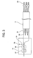
- Figure 3 is a structural diagram showing part of an elevator main rope elongation detector apparatus according to Embodiment 3 of the present invention.
- all of the carbon filaments 32 contained in one main rope 3 are electrically connected in series by a plurality of the end portion connectors 33.
- the total number of carbon filaments 32 is an even number (six in the figure), the electrical resistance measuring apparatus 11 being connected only at the first end portion of the main rope 3.
- the rest of the construction is similar to that of Embodiment 1.
- the electrical resistance measuring apparatus 11 needs to be connected only at a single end portion of the main rope 3, facilitating wiring.
- the electrical resistance measuring apparatus 11 needs to be connected only to a car end portion or to a counterweight end portion of the main rope 3, enabling the construction of the apparatus to be simplified.
- all of the carbon filaments 32 in one main rope 3 are electrically connected in series, it is not necessary to measure the electrical resistance for each of the carbon filaments 32 individually, enabling the construction of the electrical resistance measuring apparatus 11 to be simplified.
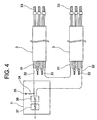
- the carbon filaments 32 in one main rope 3 were electrically connected in series, but when a plurality of main ropes 3 are used, as shown in Figure 4 for example, the construction of the electrical resistance measuring apparatus 11 can be further simplified by electrically connecting the carbon filaments 32 in series over the plurality of main ropes 3.
- FIG. 5 is a block diagram showing part of an elevator main rope elongation detector apparatus according to Embodiment 5 of the present invention.
- signals from the electrical resistance measuring apparatus 11, a temperature detector apparatus 21, and a humidity detector apparatus 22 are input into a central processing unit (CPU) 14 of the determining means 12 through input circuits 15 and 16.
- the temperature detector apparatus 21 detects temperature inside the hoistway, outputting that information to the determining means 12.
- the humidity detector apparatus 22 detects humidity inside the hoistway, outputting that information to the determining means 12.
- an abnormality detection signal is output to the warning means 13 through an output circuit 18.
- detecting precision for elongation of the main rope 3 can be improved by making a decision based not merely on a comparison between set values and the measured value, but also considering expansion and contraction of the main rope 3 due to temperature and humidity inside the hoistway.
- abnormality in the amount of elongation may also be determined by storing an initial electrical resistance in the memory 17 and comparing the measured value with this initial electrical resistance, enabling the detecting precision to be improved by eliminating the effects of initial irregularities in the main rope 3 and the carbon filaments 32.
- abnormality in the amount of elongation may also be determined from a mean value for a plurality of measured values, enabling the detecting precision to be improved by eliminating the effects of measurement errors.
- the electrical resistance in a plurality of carbon filaments 32 is measured in one main rope 3, but the elongation of the main rope 3 can be detected by measuring the electrical resistance in just one or more of the carbon filaments 32.
- reliability can be improved by measuring the electrical resistance in a plurality of the carbon filaments 32.
- carbon filaments 32 are shown as the electrically-conductive filaments, but the filaments may also be composed of any other electrically-conductive material.
- the main rope elongation detector apparatus is disposed inside the control panel 10, but the main rope elongation detector apparatus may also be disposed on the car 1 or the counterweight 2 with the abnormality detection signal being sent to the control panel 10.
- the electrical resistance may also be sought as a numerical value and determined directly, or may also be determined indirectly by measuring a voltage when a predetermined electric current is applied and determining whether that voltage is within a normal range.
Landscapes
- Lift-Guide Devices, And Elevator Ropes And Cables (AREA)
- Maintenance And Inspection Apparatuses For Elevators (AREA)
Abstract
Description
Claims (8)
- An elevator main rope elongation detector apparatus disposed in an elevator in which a car is suspended inside a hoistway by a main rope made of a synthetic fiber rope having a synthetic fiber strand and an electrically-conductive filament, said elevator main rope elongation detector apparatus detecting elongation of said main rope,
wherein said elevator main rope elongation detector apparatus comprises:an electrical resistance measuring apparatus for measuring electrical resistance in said electrically-conductive filament;a determining means for determining whether a measured value from said electrical resistance measuring apparatus is within a preset normal range; anda warning means for issuing a warning when said measured value is determined by said determining means to be outside said preset normal range. - The elevator main rope elongation detector apparatus according to Claim 1 wherein an even number of said electrically-conductive filaments is contained in said main rope so as to be grouped into pairs, said electrically-conductive filaments in each of said pairs being electrically connected to each other in series, said electrical resistance measuring apparatus being connected to only one end portion of said main rope.
- The elevator main rope elongation detector apparatus according to Claim 2 wherein all of said electrically-conductive filaments contained in said main rope are electrically connected to each other in series.
- The elevator main rope elongation detector apparatus according to Claim 1 wherein said car is suspended by a plurality of said main ropes, said electrically-conductive filaments contained in said main ropes being electrically connected to each other in series, and said electrical resistance measuring apparatus being connected to only one end portion of said plurality of main ropes.
- The elevator main rope elongation detector apparatus according to Claim 1 wherein a temperature detector apparatus for detecting temperature inside said hoistway is connected to said determining means, determination on said measured value being performed by said determining means in response to information from said temperature detector apparatus.
- The elevator main rope elongation detector apparatus according to Claim 1 wherein a humidity detector apparatus for detecting humidity inside said hoistway is connected to said determining means, determination on said measured value being performed by said determining means in response to information from said humidity detector apparatus.
- The elevator main rope elongation detector apparatus according to Claim 1 wherein a memory for storing an initial electrical resistance for said electrically-conductive filament is disposed in said determining means, determination on said measured value being performed by said determining means by a comparison of said measured value with said initial electrical resistance.
- The elevator main rope elongation detector apparatus according to Claim 1 wherein a memory for storing a plurality of said measured values is disposed in said determining means, determination being performed by said determining means using a mean value of said plurality of measured values.
Applications Claiming Priority (1)
| Application Number | Priority Date | Filing Date | Title |
|---|---|---|---|
| PCT/JP2000/008673 WO2002046082A1 (en) | 2000-12-07 | 2000-12-07 | Elevator main rope elongation sensor |
Publications (2)
| Publication Number | Publication Date |
|---|---|
| EP1357073A1 true EP1357073A1 (en) | 2003-10-29 |
| EP1357073A4 EP1357073A4 (en) | 2006-05-31 |
Family
ID=11736772
Family Applications (1)
| Application Number | Title | Priority Date | Filing Date |
|---|---|---|---|
| EP00979984A Withdrawn EP1357073A4 (en) | 2000-12-07 | 2000-12-07 | DETECTOR FOR THE ELONGATION OF A MAIN ELEVATOR CABLE |
Country Status (4)
| Country | Link |
|---|---|
| EP (1) | EP1357073A4 (en) |
| JP (1) | JPWO2002046082A1 (en) |
| CN (1) | CN1243658C (en) |
| WO (1) | WO2002046082A1 (en) |
Cited By (18)
| Publication number | Priority date | Publication date | Assignee | Title |
|---|---|---|---|---|
| US7123030B2 (en) * | 1999-03-29 | 2006-10-17 | Otis Elevator Company | Method and apparatus for detecting elevator rope degradation using electrical resistance |
| US20080149430A1 (en) * | 2006-12-04 | 2008-06-26 | Claudio De Angelis | Synthetic fiber rope |
| EP1846741A4 (en) * | 2004-03-16 | 2009-09-16 | Otis Elevator Co | Tensile support strength monitoring system and method |
| CN102933482A (en) * | 2009-12-21 | 2013-02-13 | 因温特奥股份公司 | Monitoring a supporting and propulsion means of an elevator system |
| US20130270042A1 (en) * | 2012-04-12 | 2013-10-17 | Inventio Ag | Determining states of elevator components |
| CN103738873A (en) * | 2013-12-20 | 2014-04-23 | 诺威起重设备(苏州)有限公司 | Dustproof electric hoist for cleaning room |
| US8807286B2 (en) | 2012-12-30 | 2014-08-19 | Kone Corporation | Method and an arrangement in rope condition monitoring of an elevator |
| US20140305744A1 (en) * | 2012-01-24 | 2014-10-16 | Kone Corporation | Rope of a lifting device, a rope arrangement, an elevator and a condition monitoring method for the rope of a lifting device |
| CN105060057A (en) * | 2015-09-14 | 2015-11-18 | 云南名家智能设备股份有限公司 | Steel strip detection device |
| US20150375963A1 (en) * | 2013-02-21 | 2015-12-31 | Otis Elevator Company | Elevator cord health monitoring |
| WO2016062454A1 (en) * | 2014-10-22 | 2016-04-28 | Inventio Ag | Elevator system |
| US9423369B2 (en) | 2010-09-01 | 2016-08-23 | Otis Elevator Company | Resistance-based monitoring system and method |
| WO2017032914A1 (en) * | 2015-08-21 | 2017-03-02 | Kone Corporation | Arrangement and methods for condition monitoring of the traction belt and/or the traction belt termination |
| US9599582B2 (en) | 2010-09-01 | 2017-03-21 | Otis Elevator Company | Simplified resistance based belt inspection |
| US9828214B2 (en) * | 2008-01-18 | 2017-11-28 | Kone Corporation | Synthetic fiber rope for hoisting in an elevator |
| EP3428111A1 (en) * | 2014-03-21 | 2019-01-16 | Liebherr-Components Biberach GmbH | Device for detecting the discard criteria of a cable when using hoisting gear |
| EP3527523A1 (en) * | 2018-02-19 | 2019-08-21 | Otis Elevator Company | Elevator door component monitoring systems and methods |
| US20210339984A1 (en) * | 2020-04-29 | 2021-11-04 | Tk Elevator Innovation And Operations Gmbh | Methods of monitoring the condition of elevator belts |
Families Citing this family (25)
| Publication number | Priority date | Publication date | Assignee | Title |
|---|---|---|---|---|
| EP1435407A1 (en) * | 2003-01-02 | 2004-07-07 | Teijin Twaron B.V. | Aramid filament yarn provided with a conductive finish |
| CN1926050B (en) * | 2004-03-16 | 2010-06-02 | 奥蒂斯电梯公司 | Electrical connector assemblies for use with elevator load bearing members |
| ATE465967T1 (en) | 2005-03-12 | 2010-05-15 | Thyssenkrupp Elevator Ag | ELEVATOR SYSTEM |
| KR100932589B1 (en) * | 2006-05-25 | 2009-12-17 | 미쓰비시덴키 가부시키가이샤 | Elevator device |
| JP2007320730A (en) * | 2006-06-02 | 2007-12-13 | Mitsubishi Electric Corp | Elevator door control device |
| BRPI0923524B1 (en) * | 2008-12-22 | 2021-02-23 | Inventio Ag | process for monitoring an elevator support means, elevator support means monitoring device and elevator unit with a monitoring device |
| WO2011158871A1 (en) * | 2010-06-16 | 2011-12-22 | Natac株式会社 | Method for monitoring damage to wire rope for elevator and device for monitoring damage to wire rope for elevator |
| CN102115991B (en) * | 2010-12-31 | 2012-10-03 | 北京建龙重工集团有限公司 | Steel wire rope as well as breakage early-warning device and method thereof |
| DE202011001846U1 (en) * | 2011-01-24 | 2012-04-30 | Liebherr-Components Biberach Gmbh | Device for detecting the Ablegereife a high-strength fiber rope when used on hoists |
| JP2011102195A (en) * | 2011-01-28 | 2011-05-26 | Otis Elevator Co | System and method for monitoring tension support strength |
| JP5865037B2 (en) * | 2011-11-28 | 2016-02-17 | 株式会社日立製作所 | Elevator operation management system |
| BR112014014363A2 (en) * | 2011-12-20 | 2017-06-13 | Inventio Ag | elevator installation |
| CN102530692B (en) * | 2012-03-20 | 2013-12-04 | 扬州凯思特机械有限公司 | Method for performing intelligent compensation of elongation of steel wire rope during cage bearing |
| CN102602787B (en) * | 2012-03-20 | 2014-01-08 | 扬州凯思特机械有限公司 | Intelligent compensation method and special compensation device for elongation of cage bearing steel wire rope |
| EP2909124B1 (en) * | 2012-10-22 | 2016-12-14 | Inventio AG | Load-bearing medium for a lift system |
| CN104812690B (en) * | 2012-11-29 | 2017-09-05 | 因温特奥股份公司 | Elevator device |
| CN103359567B (en) * | 2013-07-26 | 2015-10-14 | 日立电梯(中国)有限公司 | Elevator weighing system |
| EP3107855B1 (en) * | 2014-02-18 | 2020-11-18 | Otis Elevator Company | Connector for inspection system of elevator tension member |
| US10288538B2 (en) | 2015-09-30 | 2019-05-14 | Samson Rope Technologies | Non-destructive evaluation of cordage products |
| AU2018202655B2 (en) * | 2017-04-20 | 2023-12-07 | Otis Elevator Company | Tension member for elevator system belt |
| CN107352485B (en) * | 2017-07-19 | 2023-01-06 | 天奇自动化工程股份有限公司 | Elevator with belt breakage early warning function |
| US20190100408A1 (en) * | 2017-09-29 | 2019-04-04 | Otis Elevator Company | Rope deterioration detection |
| CN108275523A (en) * | 2017-12-12 | 2018-07-13 | 无锡创联科技有限公司 | It is a kind of it is vertical ladder prevent and safety monitoring system |
| WO2019130425A1 (en) * | 2017-12-26 | 2019-07-04 | 三菱電機株式会社 | Elevator |
| JP2020007078A (en) * | 2018-07-05 | 2020-01-16 | 東芝エレベータ株式会社 | Notification apparatus and notification method |
Family Cites Families (5)
| Publication number | Priority date | Publication date | Assignee | Title |
|---|---|---|---|---|
| GB2152088B (en) * | 1983-12-20 | 1986-11-12 | Bridon Plc | Detection of deterioration in rope |
| JPH05338958A (en) * | 1992-06-02 | 1993-12-21 | Mitsubishi Electric Corp | Compensation cable car equipment for elevators |
| CA2169431C (en) * | 1995-03-06 | 2005-07-12 | Claudio De Angelis | Equipment for recognising when synthetic fibre cables are ripe for being discarded |
| EP1022376B1 (en) * | 1999-01-22 | 2003-07-09 | Inventio Ag | Synthetic fibre rope |
| EP1029973B1 (en) * | 1999-01-22 | 2003-09-10 | Inventio Ag | Detection of damage to the sheath of a synthetic fibre rope |
-
2000
- 2000-12-07 CN CNB008187940A patent/CN1243658C/en not_active Expired - Fee Related
- 2000-12-07 WO PCT/JP2000/008673 patent/WO2002046082A1/en not_active Ceased
- 2000-12-07 JP JP2002547827A patent/JPWO2002046082A1/en not_active Withdrawn
- 2000-12-07 EP EP00979984A patent/EP1357073A4/en not_active Withdrawn
Cited By (32)
| Publication number | Priority date | Publication date | Assignee | Title |
|---|---|---|---|---|
| US7123030B2 (en) * | 1999-03-29 | 2006-10-17 | Otis Elevator Company | Method and apparatus for detecting elevator rope degradation using electrical resistance |
| EP1846741A4 (en) * | 2004-03-16 | 2009-09-16 | Otis Elevator Co | Tensile support strength monitoring system and method |
| US7653506B2 (en) | 2004-03-16 | 2010-01-26 | Otis Elevator Company | Tensile support strength monitoring system and method |
| US20080149430A1 (en) * | 2006-12-04 | 2008-06-26 | Claudio De Angelis | Synthetic fiber rope |
| US8360208B2 (en) * | 2006-12-04 | 2013-01-29 | Inventio Ag | Synthetic fiber rope for supporting an elevator car |
| US10843900B2 (en) | 2008-01-18 | 2020-11-24 | Kone Corporation | Rope for a hoisting device, elevator and use |
| US9828214B2 (en) * | 2008-01-18 | 2017-11-28 | Kone Corporation | Synthetic fiber rope for hoisting in an elevator |
| US11565912B2 (en) | 2008-01-18 | 2023-01-31 | Kone Corporation | Rope for a hoisting device, elevator and use |
| US8686747B2 (en) | 2009-12-21 | 2014-04-01 | Inventio Ag | Monitoring a suspension and traction means of an elevator system |
| WO2011085885A3 (en) * | 2009-12-21 | 2013-04-25 | Inventio Ag | Monitoring a supporting and propulsion means of an elevator system |
| CN102933482A (en) * | 2009-12-21 | 2013-02-13 | 因温特奥股份公司 | Monitoring a supporting and propulsion means of an elevator system |
| EP2516313B1 (en) | 2009-12-21 | 2015-04-08 | Inventio AG | Monitoring a supporting and traction means of an elevator system |
| EP2910510A1 (en) * | 2009-12-21 | 2015-08-26 | Inventio AG | Monitoring of a pull and push instrument of a lift assembly |
| AU2010342458B2 (en) * | 2009-12-21 | 2015-09-17 | Inventio Ag | Monitoring a supporting and propulsion means of an elevator system |
| AU2010342458A8 (en) * | 2009-12-21 | 2015-10-22 | Inventio Ag | Monitoring a supporting and propulsion means of an elevator system |
| US9423369B2 (en) | 2010-09-01 | 2016-08-23 | Otis Elevator Company | Resistance-based monitoring system and method |
| US9599582B2 (en) | 2010-09-01 | 2017-03-21 | Otis Elevator Company | Simplified resistance based belt inspection |
| US9834409B2 (en) * | 2012-01-24 | 2017-12-05 | Kone Corporation | Rope of a lifting device for an elevator and a condition monitoring method for the rope |
| US20140305744A1 (en) * | 2012-01-24 | 2014-10-16 | Kone Corporation | Rope of a lifting device, a rope arrangement, an elevator and a condition monitoring method for the rope of a lifting device |
| US20130270042A1 (en) * | 2012-04-12 | 2013-10-17 | Inventio Ag | Determining states of elevator components |
| US8807286B2 (en) | 2012-12-30 | 2014-08-19 | Kone Corporation | Method and an arrangement in rope condition monitoring of an elevator |
| US20150375963A1 (en) * | 2013-02-21 | 2015-12-31 | Otis Elevator Company | Elevator cord health monitoring |
| US9731939B2 (en) * | 2013-02-21 | 2017-08-15 | Otis Elevator Company | Elevator cord health monitoring |
| CN103738873A (en) * | 2013-12-20 | 2014-04-23 | 诺威起重设备(苏州)有限公司 | Dustproof electric hoist for cleaning room |
| EP3428111A1 (en) * | 2014-03-21 | 2019-01-16 | Liebherr-Components Biberach GmbH | Device for detecting the discard criteria of a cable when using hoisting gear |
| US10214396B2 (en) | 2014-03-21 | 2019-02-26 | Liebherr-Components Biberach Gmbh | Device for determining the replacement state or wear of a rope during use in lifting gear |
| WO2016062454A1 (en) * | 2014-10-22 | 2016-04-28 | Inventio Ag | Elevator system |
| US10730720B2 (en) | 2014-10-22 | 2020-08-04 | Inventio Ag | Method for monitoring elevator system suspension apparatus |
| WO2017032914A1 (en) * | 2015-08-21 | 2017-03-02 | Kone Corporation | Arrangement and methods for condition monitoring of the traction belt and/or the traction belt termination |
| CN105060057A (en) * | 2015-09-14 | 2015-11-18 | 云南名家智能设备股份有限公司 | Steel strip detection device |
| EP3527523A1 (en) * | 2018-02-19 | 2019-08-21 | Otis Elevator Company | Elevator door component monitoring systems and methods |
| US20210339984A1 (en) * | 2020-04-29 | 2021-11-04 | Tk Elevator Innovation And Operations Gmbh | Methods of monitoring the condition of elevator belts |
Also Published As
| Publication number | Publication date |
|---|---|
| CN1243658C (en) | 2006-03-01 |
| CN1433372A (en) | 2003-07-30 |
| EP1357073A4 (en) | 2006-05-31 |
| JPWO2002046082A1 (en) | 2004-04-08 |
| WO2002046082A1 (en) | 2002-06-13 |
Similar Documents
| Publication | Publication Date | Title |
|---|---|---|
| EP1357073A1 (en) | Elevator main rope elongation sensor | |
| US8807286B2 (en) | Method and an arrangement in rope condition monitoring of an elevator | |
| US6123176A (en) | Rope tension monitoring assembly and method | |
| EP2957534B1 (en) | A method and an arrangement in condition monitoring of an elevator rope | |
| CA2855873C (en) | Lift installation | |
| CN100572244C (en) | Method and system for checking condition of elevator brakes | |
| EP3461779A1 (en) | Rope deterioration detection | |
| CN101613045B (en) | Elevator running recovery method and device | |
| CN102923544B (en) | Device and method for detecting broken strands of hoisting steel wire rope | |
| CN104590962A (en) | Elevator with pulley groove diagnosing device | |
| CN108025891B (en) | Elevator device | |
| EP3640189B1 (en) | Resistance-based inspection of elevator system support members | |
| HK1248668A1 (en) | Elevator apparatus | |
| CN1951793A (en) | Automatic checking device of elevator and automatic checking method | |
| JP2002348068A (en) | Elevator rope diagnostic device | |
| AU2014273202B2 (en) | Elevator system | |
| CN214217832U (en) | Elevator wire rope breakage early warning system | |
| JP6341896B2 (en) | Elevator equipment abnormality detection method | |
| JP2017061369A (en) | Malfunction detection method for elevator equipment | |
| CN103086213B (en) | Core line checking device for tail cable used for elevator and core line checking method | |
| KR20020032099A (en) | portable diagnosis system for sefety of an elevator | |
| HK1198989B (en) | A method and an apparatus in rope condition monitoring of an elevator | |
| JPH05254751A (en) | Elevator inspection operation device | |
| JPH07206295A (en) | Elevator position detector monitoring device |
Legal Events
| Date | Code | Title | Description |
|---|---|---|---|
| PUAI | Public reference made under article 153(3) epc to a published international application that has entered the european phase |
Free format text: ORIGINAL CODE: 0009012 |
|
| 17P | Request for examination filed |
Effective date: 20020611 |
|
| AK | Designated contracting states |
Kind code of ref document: A1 Designated state(s): AT BE CH CY DE DK ES FI FR GB GR IE IT LI LU MC NL PT SE TR |
|
| AX | Request for extension of the european patent |
Extension state: AL LT LV MK RO SI |
|
| RBV | Designated contracting states (corrected) |
Designated state(s): AT BE CH CY DE FR LI NL |
|
| RAP1 | Party data changed (applicant data changed or rights of an application transferred) |
Owner name: MITSUBISHI DENKI KABUSHIKI KAISHA |
|
| A4 | Supplementary search report drawn up and despatched |
Effective date: 20060418 |
|
| STAA | Information on the status of an ep patent application or granted ep patent |
Free format text: STATUS: THE APPLICATION HAS BEEN WITHDRAWN |
|
| 18W | Application withdrawn |
Effective date: 20070924 |