Technical Field
The present relates to an elevator car load sensor for
detecting the weight of a car whose load changes during the course
of operation.
Background Art
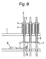
Fig. 9 shows the configuration of an example related-art
elevator car load sensor and is a front view conceptually showing
a joint of a main cable suspending a vertically-movable member.
As shown in Fig. 9, reference numeral 1 designates a cable anchor
engagement member which is formed from a member for supporting
the load of an elevator car (not shown but situated in a lower
position outside the drawing); for example, a cable anchor beam
provided in a machinery room (not shown) of an elevator system.
Reference numeral 2 designates a plurality of cable anchors
which are coupled to main cables suspending an elevator car,
are clearance-fitted into the cable anchor engagement member
1, and are arranged side by side. Reference numeral 3 designates
a nut that is screw-engaged to the end of each of the cable anchors
2; 4 designates a spring bearing which is clearance-fitted to
the end of each of the cable anchors 2 and is provided on the
side of the nut 3 facing the anchor cable engagement member 1;
and 5 designates a compressed coil spring which is
clearance-fitted to each of the cable anchors 2 and interposed
between the cable anchor engagement member 1 and the spring bearing
4.
Reference numeral 6 designates a coupling tube which is
fitted around each of the cable anchors 2 and clearance-fitted
into the anchor cable engagement member 1, and one end of the
coupling tube 6 is connected to the spring bearing 4. Reference
numeral 7 designates a detection plate into which all the cable
anchors 2 are inserted with clearance and which is connected
to the other end of each of the coupling tubes 6. Reference numeral
8 designates a detector constituted of a differential transformer
disposed on a stationary member. Reference numeral 9 designates
a transmission line which is connected at one end thereof to
an operating section of the detector 8, is coiled around a pulley
10 rotatably attached to the stationary member, and is connected
at the other end thereof to the detection plate 7.
The related-art elevator load sensor is constituted in
the above-described manner. The cable anchors 2 connected to
the main cables suspending the elevator car are supported by
the cable anchor engagement member 1 via the respective
compression coil springs 5. The compression springs 5 are
compressed in accordance with the load of the elevator car; that
is, by an amount corresponding to a sum of the self-weight of
the elevator car and a combined weight of passenger(s) in the
elevator car. The detection plate 7 is displaced in accordance
with the power of the pressure by the compression springs 5.
The detector 8 outputs an output corresponding to the amount
of displacement in the detection plate 7. In accordance with
an output from the detector 8, vertical movement of the elevator
car is controlled.
In relation to the related-art elevator car load sensor,
each of the cable anchors 2 is provided with the compression
coil springs 5. In this case, one detection plate 7 is provided
for three cable anchors 2, and one detector 8 is provided for
the detection plate 7. As mentioned above, a complicated
mechanism is constructed for detecting the weight of an elevator
car, thus adding to manufacturing costs. Another problem is a
deficiency in space for setting up hardware, thus posing
difficulty in installing the hardware. In accordance with the
inclinations of the respective cable anchors 2, an error in the
amount of displacement of the detection plate 7 increases, thus
deteriorating the accuracy of detection of weight of an elevator
car.
Disclosure of the Invention
The present invention has been conceived to solve the
above-described problems and aims at providing an elevator car
load sensor of simple construction capable of detecting the weight
of an elevator car with superior accuracy.
In an elevator car load sensor according to the present
invention, main cables supporting a car are coupled with
respective cable anchors which are arranged side by side. The
cable anchors are inserted into a cable anchor engagement member.
Insertion ends of the cable anchors are coupled to a cable anchor
plate. Elastic members which become deformed in accordance with
the weight of the car are interposed between the cable anchor
engagement member and the cable anchor plate. The elastic members
are arranged symmetrically with reference to the cable anchors
when viewed in a horizontal direction. Moreover, there is
provided a detector which produces an output corresponding to
the amount of displacement of the cable anchor plate, and an
operating section of the detector is engaged with the cable anchor
plate.
A plurality of cable anchors are engaged with one cable
anchor plate, and the cable anchor plate is resiliently supported
by the elastic members arranged symmetrically with reference
to the cable anchors. The displacement of the cable anchor plate
is detected by the detector without being affected by inclinations
of the cable anchors. Hence, the configuration of the sensor
can be simplified, and the accuracy in detection of the car's
weight can be improved.
Brief Description of the Drawings
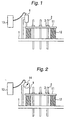
Fig. 1 is a view showing a first embodiment of the present
invention; that is, a front view conceptually showing joints
of main cables suspending a vertically-movable member;
Fig. 2 is a view showing a second embodiment of the present
invention; that is, a front view conceptually showing joints
of main cables suspending a vertically-movable member;
Fig. 3 is a view showing a third embodiment of the present
invention; that is, a front view conceptually showing joints
of main cables suspending a vertically-movable member;
Fig. 4 is a view showing a fourth embodiment of the present
invention; that is, a front view conceptually showing joints
of main cables suspending a vertically-movable member;
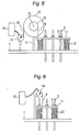
Fig. 5 is a view showing a fifth embodiment of the present
invention; that is, a front view conceptually showing joints
of main cables suspending a vertically-movable member;
Fig. 6 is a view showing a sixth embodiment of the present
invention; that is, a front view conceptually showing joints
of main cables suspending a vertically-movable member;
Fig. 7 is a view showing a seventh embodiment of the present
invention; that is, conceptually showing the routing of a main
cable in a hoistway for an elevator;
Fig. 8 is a view showing an eighth embodiment of the present
invention; that is, conceptually showing the routing of a main
cable in a hoistway for an elevator; and
Fig. 9 is a view showing a related-art elevator car load
sensor; that is, a front view conceptually showing joints of
main cables suspending a vertically-movable member.
Best Modes for Implementing the Invention
In order to describe the present invention in more detail,
an embodiment of the present invention will now be described
by reference to Fig. 1. Fig. 1 shows a first embodiment of the
invention and is a front view conceptually showing joints of
main cables suspending a vertically-movable member.
As shown in Fig. 1, reference numeral 1 designates a cable
anchor engagement member (or a cable anchor plate) for supporting
an elevator car (not shown but located in a lower position outside
the drawing). The cable anchor engagement member 1 is formed
from, e.g., a cable anchor beam provided in a machinery room
(not shown) of an elevator system.
Reference numeral 2 designates a plurality of cable anchors
(or rope shackles). A plurality of main cables 2A supporting
an elevator car are coupled to the respective cable anchors 2,
are clearance-fitted into the cable anchor engagement member
1, and are provided side by side. Reference numeral 3 designates
nuts screwed to insertion ends of the respective cable anchors
2. Reference numeral 11 designates a cable anchor plate (or
detection plate) which is interposed between the cable anchor
engagement member 1 and the nuts 3 and into which the cable anchors
2 arranged side by side are clearance-fitted.
Reference numeral 12 designates elastic members (e.g.,
coil springs). The elastic members 12 are interposed between
the cable anchor engagement member 1 and the cable anchor plate
11. The elastic members 12 are disposed symmetrically with
respect to the cable anchors 2 when viewed in a horizontal direction
and become deformed in accordance with the weight of the car.
The elastic members 12 are provided on, e.g., respective ends
of the cable anchor plate 11. Consequently, the cable anchor
plate 11 becomes linearly and vertically deformed in accordance
with the weight of the car.
Reference numeral 8 designates a detector constituted of
a differential transformer disposed on a stationary member, and
an operating section of the detector 8 is engaged with the cable
anchor plate 11 and operates through forward and backward
displacement actions. Reference numeral 13 designates a control
circuit which is connected to the detector 8 and acquires, in
real time, an output from the detector 8 responsive to the amount
of displacement of the anchor plate 11 corresponding to the weight
of the car, to thereby control vertical movement of the car.
For instance, an output from the detector 8 can be utilized for
detecting overload by way of the control circuit 13, regulating
motor torque on startup (an improvement in ride comfort), and
group management (an improvement in service).
In relation to the elevator car load sensor constructed
in the above-described manner, the weight of the elevator car
acting on each of the cable anchors 2 is collectively supported
by the plurality of elastic members 12 by way of the single cable
anchor plate 11. In other words, the loads exerted on the
respective main cables 2A (e.g., ropes) are temporarily summed
by the cable anchor plate 11. The thus-summed load is distributed
to the respective springs. For this reason, if the number of
cable anchors 2 or ropes is increased, there is no necessity
for increasing the number of elastic members 12 and detectors
8.
Consequently, a mechanism for accurately sensing the
weight of a car can be simplified and readily installed, and
savings can be realized in the cost of the car weight sensing
mechanism. Since the plurality of cable anchors 2 are engaged
with the single cable anchor plate 11, no inclination arises
in the cable anchors 2, which would otherwise be caused by the
weight of the car. Hence, there can be prevented occurrence of
a drop in the accuracy of detection of weight of the car, which
would otherwise be caused by inclinations of the cable anchors
2. Hence, an operation for vertically moving the car can be
controlled normally.
In order to describe the present invention in more detail,
another embodiment of the present invention will be described
by reference to Fig. 2. Fig. 2 is a diagram showing a second
embodiment of the present invention; that is, a front view
conceptually showing joints of the main cables supporting a
vertically-movable member.
In Fig. 2, those reference numerals which are identical
with those provided in Fig. 1 correspond to the same elements.
Reference numeral 14 designates a detector which is composed
of a potentiometer, is provided on a stationary member, and
operates through pivotal displacement. An operating section of
the detector is engaged with the cable anchor plate 11 via a
transmission line 9 (e.g., wire). By means of such a construction,
straight displacement of the cable anchor plate 11 is converted
into a rotational angle by means of taking up the transmission
line 9, and the detector 14 constituted of a potentiometer detects
the angular displacement.
Even in the elevator car load sensor constructed in the
manner set forth, the plurality of cable anchors 2 are engaged
with the cable anchor plate 11 supported by the plurality of
elastic members 12. Displacement of the cable anchor plate 11
due to the weight of the car is detected by the detector 14.
Consequently, although detailed descriptions are omitted, the
embodiment shown in Fig. 2 also yields the same advantage as
that yielded in the embodiment shown in Fig. 1.
In order to describe the present invention in more detail,
yet another embodiment of the present invention will be described
by reference to Fig. 3. Fig. 3 is a diagram showing a third
embodiment of the present invention; that is, a front view
conceptually showing joints of main cables supporting a
vertically-movable member.
In Fig. 3, those reference numerals which are identical
with those provided in Fig. 1 correspond to the same elements.
Reference numeral 15 designates a pivotal transmission mechanism
which is provided on a stationary member and equipped with the
transmission line 9 engaged with the cable anchor plate 11.
Reference numeral 8 designates a detector constituted of an
acceleration sensor which operates while being connected to the
pivotal transmission mechanism 15. By means of such a
construction, straight displacement of the cable anchor plate
11 is converted into a rotational angle by means of taking up
the transmission line 9, and the detector 8 constituted of an
acceleration sensor detects the angular displacement.
Even in the elevator car load sensor constructed in the
manner set forth, the plurality of cable anchors 2 are engaged
with the cable anchor plate 11 supported by the plurality of
elastic members 12. Displacement of the cable anchor plate 11
due to the weight of the car is detected by the detector 8.
Consequently, although detailed descriptions are omitted, the
embodiment shown in Fig. 3 also yields the same advantage as
that yielded in the embodiment shown in Fig. 1.
In order to describe the present invention in more detail,
still another embodiment of the present invention will be
described by reference to Fig. 4. Fig. 4 is a diagram showing
a fourth embodiment of the present invention; that is, a front
view conceptually showing joints of main cables supporting a
vertically-movable member.
In Fig. 4, those reference numerals which are identical
with those provided in Figs. 1 and 2 correspond to the same elements.
Reference numeral 16 designates an enlargement transmission
mechanism provided. The enlargement transmission mechanism 16
comprises a pillar-like member 17 provided on the stationary
member in an upright position; an arm member 18 whose
longitudinally-intermediate point is pivotally attached to the
pillar-like member 17; a first transmission line 9 which is
connected to one end of the arm member 18 and engaged with the
cable anchor plate 11; and a second transmission line 19 connected
to the other end of the arm member 18 and to a detector 14, wherein
the second transmission line 19 is spaced a much longer distance
from the pivotally-attachment point of the arm member 18 than
is the first transmission line 9 is. By means of such a structure,
displacement of the cable anchor plate 11 is enlarged by the
enlargement transmission mechanism 16, and the detector 14
constituted of a potentiometer detects the thus-enlarged
displacement.
Even in the elevator car load sensor having the foregoing
construction, the plurality of anchor cables 2 are engaged with
the cable anchor plate 11 by means of the plurality of elastic
members 12. The displacement of the cable anchor plate 11 due
to the weight of the car is detected by the detector 14 by way
of the enlargement transmission mechanism 16. Consequently,
although detailed descriptions are omitted, the embodiment shown
in Fig. 4 also yields the same advantage as that yielded in the
embodiment shown in Fig. 1.
In order to describe the present invention in more detail,
another embodiment of the present invention will be described
by reference to Fig. 5. Fig. 5 is a diagram showing a fifth
embodiment of the present invention; that is, a front view
conceptually showing joints of main cables supporting a
vertically-movable member.
In Fig. 5, those reference numerals which are identical
with those provided in Figs. 1 and 4 correspond to the same elements.
Reference numeral 20 designates a rotary enlargement transmission
mechanism. The rotary enlargement transmission mechanism 20
comprises a pillar-like member 17 provided on the stationary
member in an upright position; a smaller pulley 21 pivotally
attached to the pillar-like member 17; a larger pulley 22 fixed
to the smaller pulley 21; a first transmission line 9 (e.g.,
a wire) which is at one end coupled to the smaller pulley 21
and at the other end engaged with the cable anchor plate 11;
and a second transmission line 19 (e.g., a wire) which is at
one end coupled to the larger pulley 22 and at the other end
connected to the detector 14. By means of such a structure,
displacement of the cable anchor plate 11 is enlarged by way
of the wires and the two pulleys 21, 22 which are of different
diameters, and the detector 14 detects the thus-enlarged
displacement, thereby enabling accurate detection of minute
displacement.
Even in the elevator car load sensor constructed in the
manner as mentioned above, the plurality of anchor cables 2 are
engaged with the cable anchor plate 11 by means of the plurality
of elastic members 12. The displacement of the cable anchor plate
11 due to the weight of the car is enlarged by way of the rotation
enlargement mechanism 20, and the thus-enlarged displacement
is detected by the detector 14. Consequently, although detailed
descriptions are omitted, the embodiment shown in Fig. 5 also
yields the same advantage as that yielded in the embodiment shown
in Fig. 1.
In order to describe the present invention in more detail,
another embodiment of the present invention will be described
by reference to Fig. 6. Fig. 6 is a diagram showing a sixth
embodiment of the present invention; that is, a front view
conceptually showing joints of the main cables supporting a
vertically-movable member.
In Fig. 6, those reference numerals which are identical
with those provided in Fig. 2 correspond to the same elements.
Reference numeral 23 designates elastic members which are each
constituted of a compression coil spring, are fitted around the
cable anchors 2 disposed on respective ends of the cable anchor
plate 11, are interposed between the cable anchor engagement
member 1 and the cable anchor plate 11, are disposed symmetrically
with reference to the positions of the cable anchors 2 when viewed
in horizontal direction, and are compressed in accordance with
the load of the car. In other words, the elastic members 23 are
provided in the same positions as those of the cable anchors
2. As a result, the entirety of the elevator car load sensor
is made compact, thereby realizing space savings. Further, the
moment exerted on the cable anchor plate 11 is diminished, and
hence the structure member can be made thin, thereby realizing
weight reduction and saving of raw materials.
Even in the elevator car load sensor constructed in the
manner as mentioned above, the plurality of anchor cables 2 are
engaged with the cable anchor plate 11 supported by the elastic
members 12. The displacement of the cable anchor plate 11 due
to the weight of the car is detected by the detector 14.
Consequently, although detailed descriptions are omitted, the
embodiment shown in Fig. 6 also yields the same advantage as
that yielded in the embodiment shown in Fig. 1. The elastic
members 23 are fitted around the cable anchors 2 disposed at
the respective ends of the cable anchor plate 11. For this reason,
the space for setting up the load sensor can be saved with reference
to the horizontal direction, and installation of the load sensor
can be simplified.
In order to describe the present invention in more detail,
another embodiment of the present invention will be described
by reference to Fig. 7. Fig. 7 is a diagram showing a seventh
embodiment of the present invention; that is, conceptually
showing extension of main cables in the hoistway of an elevator
system. In other respects, the elevator car load sensor shown
in Fig. 7 is constructed in the same manner as that described
in connection with the embodiment shown in Fig. 1.
In Fig. 7, those reference numerals which are identical
with those provided in Fig. 1 correspond to the same elements.
Reference numeral 1 designates a cable anchor engagement member;
that is, a member for supporting the load of an elevator car,
and the cable anchor engagement member 1 is formed from a cable
anchor beam provided in the machinery room of the elevator system.
Reference numeral 24 designates a stationary pulley
pivotally attached to a fixed section of the machinery room of
the elevator system; 25 designates a car which moves vertically
along a predetermined path in the hoistway of the elevator system;
26 designates a counterweight which moves vertically along
another predetermined path in the hoistway of the elevator system;
and 27 designates a main cable. One end of the main cable 27
is coupled to the cable anchor 2 inserted into the cable anchor
plate 11, and the main cable 27 is coiled around pulleys provided
on the car 25, the stationary pulley 24, and a pulley provided
on the counterweight 26. The other end of the main cable 27 is
coupled to the cable anchor 2 inserted into the cable anchor
beam 1 provided in the machinery room.
Reference numeral 28 designates an elastic member for
regulating tensile force, which is formed from a compression
coil spring. The elastic member 28 is fitted around the cable
anchor 2 inserted into the cable anchor plate 11, and interposed
between the nut 3 fitted around and screwed to the insertion
end of the cable anchor 2, and the cable anchor plate 11. The
other elastic member 28 for regulating tensile force is fitted
around the cable anchor 2 inserted into the cable anchor beam
1 provided in the machinery room. The elastic member 28 is
interposed between the nut 3 fitted around and screwed to the
insertion end of the cable anchor 2, and the cable anchor beam
1. Either or both the elastic members 28 may be provided.
Even in the elevator car load sensor constructed in the
manner as mentioned above, the plurality of anchor cables 2 are
engaged with the cable anchor plate 11 by means of the plurality
of elastic members 12. The displacement of the cable anchor plate
11 due to the weight of the car is detected by the detector 14.
Consequently, although detailed descriptions are omitted, the
embodiment shown in Fig. 7 also yields the same advantage as
that yielded in the embodiment shown in Fig. 1. Moreover, since
the cable anchor 2 is engaged with the cable anchor plate 11
via the elastic member 28 for regulating tensile force, the tensile
force of the main cable can be regulated readily.
In order to describe the present invention in more detail,
another embodiment of the present invention will be described
by reference to Fig. 8. Fig. 8 is a diagram showing a seventh
embodiment of the present invention; that is, conceptually
showing extension of main cables in the hoistway of an elevator
system. In other respects, the elevator car load sensor shown
in Fig. 8 is constructed in the same manner as that described
in connection with the embodiment shown in Fig. 1. In Fig. 8,
those reference numerals which are identical with those provided
in Fig. 7 correspond to the same elements.
Reference numeral 1 designates a cable anchor engagement
member; that is, a member for supporting the load of the elevator
car 25, and the cable anchor engagement member 1 is formed from
an upper frame of the car 25. Reference numeral 29 designates
a traction machine disposed in an elevator machine room; and
30 designates a main cable. One end of the main cable 30 is coupled
to the cable anchor 2 inserted into the cable anchor plate 11,
and the main cable 30 is coiled around a sheave of the traction
machine 29. The other end of the main cable 30 is connected to
the cable anchor 2 inserted into an upper frame of the counterweight
26.
Reference numeral 28 designates an elastic member for
regulating tensile force, which is formed from a compression
coil spring. The elastic member is fitted around the cable anchor
2 inserted into the cable anchor plate 11, and interposed between
the nut 3 fitted around and screwed to the insertion end of the
cable anchor 2, and the cable anchor plate 11. The other elastic
member 28 for regulating tensile force is fitted around the cable
anchor 2 inserted into an upper frame of the counterweight 26
and interposed between the nut 3 fitted around and screwed to
the insertion end of the cable anchor 2, and the upper frame
of the counterweight 26. Either or both of the elastic members
28 may be provided.
Even in the elevator car load sensor constructed in the
manner as mentioned above, the plurality of anchor cables 2 are
engaged with the cable anchor plate 11 by means of the plurality
of elastic members 12. The displacement of the cable anchor plate
11 due to the weight of the car is detected by the detector 14.
Further, the elastic members 28 are provided. Consequently,
although detailed descriptions are omitted, the embodiment shown
in Fig. 8 also yields the same advantage as that yielded in the
embodiments shown in Figs. 1 and 7.
The first through sixth embodiments have exemplified the
case of three main cables 2A. However, the main cables 2A may
number ??two or ??more than three. Moreover, there have been
exemplified cases where the elastic members (coil springs) 12
are provided at respective ends of the cable anchor 2. In a case
where the number of main cables 2A has increased, the elastic
members 12 may be provided at the respective corners of a rectangle.
Although, for the sake of brevity, the seventh and eighth
embodiments have illustrated one main cable, a plurality of main
cables may be provided.
Industrial Applicability
As has been described, in an elevator car load sensor
according to the present invention, the weight of a car acting
on respective cable anchors is collectively supported by elastic
members by way of a cable anchor plate. Even when the number
of cable anchors is increased, there is no necessity of increasing
the number of elastic members and the number of detectors.
Consequently, a mechanism of detecting the weight of the car
can be simplified and readily set up. Further, expenses to be
incurred by a car weight detection mechanism can be saved. For
these reasons, the present invention is useful as an elevator
car load sensor for detecting the weight of a car relevant to
load which is to change during the course of operation of the
car.
Since a plurality of cable anchors are engaged with a
single cable anchor plate, there is prevented occurrence of
inclination of cable anchors, which would otherwise be caused
by the weight of the car. Further, there can be prevented
occurrence of a drop in the accuracy of detection of weight of
the car, which would otherwise be caused by inclination of the
cable anchors. Thus, the elevator car load sensor is suitable
for normalizing operation control of the car.