EP1356983A1 - Seat cushion for vehicle seat unit - Google Patents
Seat cushion for vehicle seat unit Download PDFInfo
- Publication number
- EP1356983A1 EP1356983A1 EP03007682A EP03007682A EP1356983A1 EP 1356983 A1 EP1356983 A1 EP 1356983A1 EP 03007682 A EP03007682 A EP 03007682A EP 03007682 A EP03007682 A EP 03007682A EP 1356983 A1 EP1356983 A1 EP 1356983A1
- Authority
- EP
- European Patent Office
- Prior art keywords
- tuck
- conductive film
- seat cushion
- seat
- planar
- Prior art date
- Legal status (The legal status is an assumption and is not a legal conclusion. Google has not performed a legal analysis and makes no representation as to the accuracy of the status listed.)
- Granted
Links
- 230000002787 reinforcement Effects 0.000 claims abstract description 6
- 230000000717 retained effect Effects 0.000 claims abstract description 4
- 210000002105 tongue Anatomy 0.000 claims description 4
- -1 polyethylene terephthalate Polymers 0.000 description 16
- 229920000139 polyethylene terephthalate Polymers 0.000 description 15
- 239000005020 polyethylene terephthalate Substances 0.000 description 15
- 238000005452 bending Methods 0.000 description 13
- 239000000758 substrate Substances 0.000 description 9
- 230000003014 reinforcing effect Effects 0.000 description 8
- JOYRKODLDBILNP-UHFFFAOYSA-N Ethyl urethane Chemical compound CCOC(N)=O JOYRKODLDBILNP-UHFFFAOYSA-N 0.000 description 6
- 230000008602 contraction Effects 0.000 description 6
- 238000010438 heat treatment Methods 0.000 description 6
- 239000010410 layer Substances 0.000 description 6
- 229920003023 plastic Polymers 0.000 description 6
- 239000004033 plastic Substances 0.000 description 6
- 230000004044 response Effects 0.000 description 6
- 230000008719 thickening Effects 0.000 description 6
- 239000004642 Polyimide Substances 0.000 description 4
- 229920001721 polyimide Polymers 0.000 description 4
- 239000006260 foam Substances 0.000 description 3
- 230000003292 diminished effect Effects 0.000 description 2
- 238000006073 displacement reaction Methods 0.000 description 2
- 238000010521 absorption reaction Methods 0.000 description 1
- 239000012790 adhesive layer Substances 0.000 description 1
- 230000015572 biosynthetic process Effects 0.000 description 1
- 230000000903 blocking effect Effects 0.000 description 1
- 239000004744 fabric Substances 0.000 description 1
- 238000010348 incorporation Methods 0.000 description 1
- 239000010985 leather Substances 0.000 description 1
- 238000004519 manufacturing process Methods 0.000 description 1
- 239000000463 material Substances 0.000 description 1
- 230000007246 mechanism Effects 0.000 description 1
- 238000000034 method Methods 0.000 description 1
- 229910001120 nichrome Inorganic materials 0.000 description 1
- 230000008569 process Effects 0.000 description 1
- 230000001681 protective effect Effects 0.000 description 1
- 238000000926 separation method Methods 0.000 description 1
- 125000006850 spacer group Chemical group 0.000 description 1
- 229920003002 synthetic resin Polymers 0.000 description 1
- 239000000057 synthetic resin Substances 0.000 description 1
Images


Classifications
-
- B—PERFORMING OPERATIONS; TRANSPORTING
- B60—VEHICLES IN GENERAL
- B60N—SEATS SPECIALLY ADAPTED FOR VEHICLES; VEHICLE PASSENGER ACCOMMODATION NOT OTHERWISE PROVIDED FOR
- B60N2/00—Seats specially adapted for vehicles; Arrangement or mounting of seats in vehicles
- B60N2/56—Heating or ventilating devices
- B60N2/5678—Heating or ventilating devices characterised by electrical systems
- B60N2/5685—Resistance
-
- B—PERFORMING OPERATIONS; TRANSPORTING
- B60—VEHICLES IN GENERAL
- B60N—SEATS SPECIALLY ADAPTED FOR VEHICLES; VEHICLE PASSENGER ACCOMMODATION NOT OTHERWISE PROVIDED FOR
- B60N2/00—Seats specially adapted for vehicles; Arrangement or mounting of seats in vehicles
- B60N2/002—Seats provided with an occupancy detection means mounted therein or thereon
- B60N2/0021—Seats provided with an occupancy detection means mounted therein or thereon characterised by the type of sensor or measurement
- B60N2/003—Seats provided with an occupancy detection means mounted therein or thereon characterised by the type of sensor or measurement characterised by the sensor mounting location in or on the seat
- B60N2/0033—Seats provided with an occupancy detection means mounted therein or thereon characterised by the type of sensor or measurement characterised by the sensor mounting location in or on the seat mounted on or in the foam cushion
-
- B—PERFORMING OPERATIONS; TRANSPORTING
- B60—VEHICLES IN GENERAL
- B60N—SEATS SPECIALLY ADAPTED FOR VEHICLES; VEHICLE PASSENGER ACCOMMODATION NOT OTHERWISE PROVIDED FOR
- B60N2/00—Seats specially adapted for vehicles; Arrangement or mounting of seats in vehicles
- B60N2/002—Seats provided with an occupancy detection means mounted therein or thereon
- B60N2/0021—Seats provided with an occupancy detection means mounted therein or thereon characterised by the type of sensor or measurement
- B60N2/003—Seats provided with an occupancy detection means mounted therein or thereon characterised by the type of sensor or measurement characterised by the sensor mounting location in or on the seat
- B60N2/0034—Seats provided with an occupancy detection means mounted therein or thereon characterised by the type of sensor or measurement characterised by the sensor mounting location in or on the seat in, under or on the seat cover
-
- B—PERFORMING OPERATIONS; TRANSPORTING
- B60—VEHICLES IN GENERAL
- B60N—SEATS SPECIALLY ADAPTED FOR VEHICLES; VEHICLE PASSENGER ACCOMMODATION NOT OTHERWISE PROVIDED FOR
- B60N2/00—Seats specially adapted for vehicles; Arrangement or mounting of seats in vehicles
- B60N2/24—Seats specially adapted for vehicles; Arrangement or mounting of seats in vehicles for particular purposes or particular vehicles
- B60N2/26—Seats specially adapted for vehicles; Arrangement or mounting of seats in vehicles for particular purposes or particular vehicles for children
- B60N2/266—Seats specially adapted for vehicles; Arrangement or mounting of seats in vehicles for particular purposes or particular vehicles for children with detection or alerting means responsive to presence or absence of children; with detection or alerting means responsive to improper locking or installation of the child seats or parts thereof
-
- B—PERFORMING OPERATIONS; TRANSPORTING
- B60—VEHICLES IN GENERAL
- B60N—SEATS SPECIALLY ADAPTED FOR VEHICLES; VEHICLE PASSENGER ACCOMMODATION NOT OTHERWISE PROVIDED FOR
- B60N2/00—Seats specially adapted for vehicles; Arrangement or mounting of seats in vehicles
- B60N2/58—Seat coverings
- B60N2/5816—Seat coverings attachments thereof
- B60N2/5825—Seat coverings attachments thereof by hooks, staples, clips, snap fasteners or the like
-
- B—PERFORMING OPERATIONS; TRANSPORTING
- B60—VEHICLES IN GENERAL
- B60R—VEHICLES, VEHICLE FITTINGS, OR VEHICLE PARTS, NOT OTHERWISE PROVIDED FOR
- B60R21/00—Arrangements or fittings on vehicles for protecting or preventing injuries to occupants or pedestrians in case of accidents or other traffic risks
- B60R21/01—Electrical circuits for triggering passive safety arrangements, e.g. airbags, safety belt tighteners, in case of vehicle accidents or impending vehicle accidents
- B60R21/015—Electrical circuits for triggering passive safety arrangements, e.g. airbags, safety belt tighteners, in case of vehicle accidents or impending vehicle accidents including means for detecting the presence or position of passengers, passenger seats or child seats, and the related safety parameters therefor, e.g. speed or timing of airbag inflation in relation to occupant position or seat belt use
- B60R21/01512—Passenger detection systems
- B60R21/0153—Passenger detection systems using field detection presence sensors
- B60R21/01532—Passenger detection systems using field detection presence sensors using electric or capacitive field sensors
-
- B—PERFORMING OPERATIONS; TRANSPORTING
- B60—VEHICLES IN GENERAL
- B60N—SEATS SPECIALLY ADAPTED FOR VEHICLES; VEHICLE PASSENGER ACCOMMODATION NOT OTHERWISE PROVIDED FOR
- B60N2210/00—Sensor types, e.g. for passenger detection systems or for controlling seats
- B60N2210/40—Force or pressure sensors
Definitions
- the present invention relates to a seat cushion for a vehicle seat unit that comprises a cushioning pad such as an urethane foam upholstered with a seat covering, and, more particularly, to a seat cushion for a vehicle seat unit in which a planer electrically conductive element is disposed between a cushioning pad and a seat covering.
- a cushioning pad such as an urethane foam upholstered with a seat covering
- a seat cushion of a front seat unit or a rear seat unit for a vehicle comprises an elastic cushioning pad such as an urethane pad and a seat covering with which the elastic cushioning pad is upholstered.
- Some types of seat cushion are provided with a planar conductive element such as comprised of a flexible but inelastic planar film with an electrically conductive element buried therein (that is hereafter referred to as a planar conductive film) that is disposed between the cushioning pad and the seat covering.
- the planar conductive film is used as a planar sensor device that detects an occupant sitting on the seat cushion or an occupant such as an infant or a small child secured in a child safety seat on the seat cushion.
- a seat cushion 80 comprises an elastic cushioning pad 81 preferably made of an urethane foam with its seating surface entirely upholstered with a seat covering (not shown).
- the seat cushion 80 is provided with a flexible but inelastic planar conductive film 82 embedded therein between the seat cushioning pad 81 and the seat covering.
- the elastic cushioning pad 81 has a plurality of U-shaped tuck-in grooves 83 (only one of which is shown) extending in both lengthwise and transverse directions.
- the seat covering is locally retained the tuck-in grooves 83 for preserving a designed appearance of the seat cushion 80, and strip sections of the planer conductive film 82 are laid in the tuck-in grooves 83 in a U- or V-shape.
- the seat cushion 80 when the seat cushion 80 repeatedly experiences an external impact load from above, while the cushioning pad 81 elastically contracts and recovers repeatedly, nevertheless, the planar conductive film 82 dos not contract.
- the strip sections of the planar conductive film 82 in the tuck-in grooves 83 are repeatedly loosened and stretched and led into breakage or damage as shown in Figure 11.
- Such breakage or damage of the strip section of the planar conductive film 82 causes an electric disconnection of the electrically conductive element at the broken or damaged strip section laid in the tuck-in groove 83.
- the electric disconnection of the electrically conductive element is made more marked, if the tuck-in grooves 83 is made deeper for design requirements.
- Modified shapes of tuck-in groove 83 such as shown in Figures 12 through 15 are conceivably effective to eliminate an occurrence of breakage or damage of the strip section of the planar conductive film 82 in the tuck-in groove 83.
- a cushioning pad 81 has a tuck-in groove 83 locally provided with bridges 84 so that the tuck-in groove 83 is locally made shallow at locations where strip sections of a planar conductive film 82 traverse the tuck-in groove 83.
- the seat cushion 80 having the cushioning pad 81 with the tuck-in grooves 83 locally made shallow, while the planar conductive film 82 is advantageously prevented from causing breakage or damage that is conductive to an electric disconnection of the electrically conductive element buried in the planer conductive film 82, nevertheless, the tuck-in groove 83 at the bridges 84 is made too shallow for the seat covering to provide a sufficient tuck-in depth for the seat covering. This tends toward an unattractive appearance of the seat cushion 80 and, in consequence, leads the seat unit into less marketability.
- a cushioning pad 81 has a tuck-in groove 83 locally provided a narrow inverted trapezoidal recesses 85 across the tuck-in grooves 83 at locations where strip sections of a planar conductive film 82 are laid in the tuck-in grooves 83.
- the inverted trapezoidal recess 85 comprises a flat bottom 85a at a level with the bottom of the tuck-in groove 83 and walls 85b slanting in opposite directions.
- triangular retaining pads 85c are forced into triangular spaces formed in the cushioning pad 81 by the inverted trapezoidal recess 85 at opposite sides of the tuck-in groove 83 so as thereby to prevent the strip section of the planer conductive film 82 from coming up.
- the triangular retaining pad 85 is preferably different in material from the cushioning pad 81.
- a cushioning pad 81 has a tuck-in groove 83 and inverted trapezoidal grooves 86 across the tuck-in groove 83 at locations where strip sections of a planar conductive film 82 is laid in the tuck-in grooves 83.
- the inverted trapezoidal groove 86 at opposite sides has an open top end flanked with a pair of rounded retaining protrusions 87 at each of opposite sides of the tuck-in groove 83.
- Each rounded retaining protrusion 87 is formed as an integral portion of the cushioning pad 81.
- the strip section of the planar conductive film 82 is forced into the inverted trapezoidal groove 86 passing through the retaining protrusions 87 and laid in the tuck-in groove 83.
- the strip section of the planar conductive film 82 is prevented from coming up and out of the tuck-in groove 83 by the retaining protrusions 87. While the tuck-in groove 83 thus constructed is advantageous in preventing the planar conductive film 82 from being damaged or broken, and hence an electric disconnection of the electrically conductive element, nevertheless, the tuck-in groove 83 inevitably reaches aggravation of setting easiness of the strip sections of the planar conductive film 82.
- the retaining protrusion 87 is made larger in order to prevent the strip section of the planar conductive film 82 from coming up and out of the tuck-in groove 83, it becomes an onerous task to tuck the strip section of the planar conductive film 82 in the tuck-in groove 83.
- planar occupant sensor has a protective sheet with an extension inserted between cushioning pad of a seatback and an adhesive layer so as to prevent the electrically conductive layer or film from breaking.
- the protection sheet is used only for protecting the electrically conductive layer or film.
- the electrically conductive layer or film is not laid in tuck-in grooves.
- a pattern crack an electric disconnection
- a seat cushion for a vehicle seat unit that comprises a cushioning pad such as an urethane foam, a seat covering such as a cloth seat covering or a leather seat covering with which the cushioning pad is upholstered, and a flexible but inelastic planar conductive element (which comprises a flexible and inelastic film and an electrically conductive element buried in the flexible and inelastic film and is hereafter referred to as a planer conductive film for simplicity) disposed between the cushioning pad and the seat covering.
- the cushioning pad has a plurality of generally U-shaped tuck-in grooves in which the seat covering is locally retained.
- the planer conductive element is locally made thicker for reinforcement than the remaining portion thereof at locations where the planar conductive element traverses the tuck-in grooves.
- the planar conductive film is such as to be used as a planar sensor device that detects presence of an occupant sitting on the seat cushion or an occupant such as an infant or a small child secured in a child safety seat on the seat cushion or as a planar seat heater.
- the planar conductive film causes less local slacks or inelastic bending in the tuck-in grooves through the instrumentally of the reinforcement and sustains less breakage or damage.
- the planar conductive film prevents the electrically conductive element buried in the film from sustaining what is called pattern cracks (electric disconnections).
- planar conductive film causes local slacks or inelastic bending in the tuck-in grooves when the seat cushion contracts due to an external impact force from above, the planar conductive film slides on the cushioning pad to produce widespread flexure over the entire area thereof, so that the local slacks or inelastic bending in the tuck-in grooves are dispersed through the flexure and then diminished. Since the tuck-in grooves are not crushed, the seat cushion keeps its attractive appearance.
- the planer conductive film is locally made more slippery and/or more elastic for reinforcement than the remaining portion thereof at locations where the planar conductive element traverses the tuck-in grooves.
- the planar conductive film at the slippery or elastic portions diminishes in frictional drag against the cushioning pad.
- the slippery or elastic portion is realized by fixing a segmental plastic piece made of polyethylene terephthalate or polyimide to the planar conductive film, or otherwise by thickening the planar conductive film so as to provide it locally with increased elasticity.
- planar conductive film provided with reinforced portions made slippery or elastic is hardly bendable in the tuck-in grooves, so that the planar conductive film prevents the electrically conductive element buried in the film from sustaining what is called pattern cracks (electric disconnections) due to slacks or inelastic bending.
- planar conductive film causes local slacks or inelastic bending in the tuck-in grooves when the seat cushion contracts due to an external impact force from above, the planar conductive film slides on the cushioning pad to produce widespread flexure over the entire area thereof, so that the local slacks or inelastic bending in the tuck-in grooves are dispersed through the widespread flexure of the planar conductive film and then diminished. Accordingly, the planar conductive film is protected against an electric disconnection without making the tuck-in grooves of the cushioning pad shallow or otherwise blocking portions of the tuck-in grooves crossed over by the planar conductive film.
- the reinforced portion may be formed by fixing a segmental plastic piece to either one or both of opposite surfaces of the planar conductive film.
- the segmental plastic piece is preferred to be made of polyethylene terephthalate or polyimide in light of thickness, slipping performance and elasticity.
- the reinforced portion may be formed in a lengthwise direction of the planer conductive film, in other words in a direction perpendicular to the tuck-in groove.
- the planar conductive film at the reinforced portions provides elasticity and restoration more effectively with respect to the tuck-in grooves, so as thereby to prevent the electrically conductive element from sustaining pattern cracks or electric disconnections.
- the planar conductive film at the reinforced portions may be provided with integrated tongues extending perpendicularly from opposite lengthwise sides of the planar conductive film, in other words in a lengthwise direction of the tuck-in groove.
- the planar conductive film at the reinforced portions is prevented from causing positional displacement due to increased thickness, enhanced slippage performance and elasticity when the seat cushion receives external impact force from above and, in consequence, provides positioning convenience.
- the planar conductive film may be used as a planar sensor device that detects an occupant condition, e.g. presence of an occupant or a commodity, occupant type and/or occupant location, in order to control actuation of, for example, an occupant associated protection system such as an air bag in response to a detected occupant condition.
- the planar sensor device includes a planar array of pressure sensors operative to turn conductive when receiving external impact force from above. The planar sensor device is prevented from causing a pattern crack or electric disconnection of the planar array of pressure sensors, the occupant protection system is appropriately controlled in actuation.
- the planar conductive film may be used as a planar seat heater.
- the planar seat heater is prevented from causing a pattern crack or electric disconnection of a heating wire.
- the seat cushion 1 comprises an elastic cushioning pad 2 made of such as urethane, a patterned planar conductive film 8 that is flexible but inelastic and a seat covering 3.
- the elastic cushioning pad 2 is formed as one integral piece and comprises three sections, namely a seat section 2A and two side support sections 2B at opposite side of the seat section 2A.
- the elastic cushioning pad 2 has a lengthwise tuck-in groove 4 formed along a border between the seat section 2A and each side support section 2B and two transverse tuck-in grooves 5 formed in a central portion of the seat section and extending between the opposite lengthwise tuck-in grooves 4.
- wires 6 are embedded below the respective tuck-in grooves 4 and 5 in the elastic cushioning pad 2.
- the wires 6 has hooks 7 partly protruding into the tuck-in grooves 4 and 5 so as retain the seat covering 3 locally in the tuck-in grooves 4 and 5 in U- or V-shape for preserving a designed configuration of the seat cushion 1.
- the patterned planer conductive film 8 such as made of a synthetic resin film is comprised of a center lengthwise strip section 8A, side lengthwise strip sections 8B at centers of the side support sections 2B, a number of transverse strip sections 8C connecting the side lengthwise strip sections 8B to the center lengthwise strip section 8A and a base section 8D at a front end of the center lengthwise strip section 8A.
- the patterned planar conductive film 8 is provided with a plurality of pressure sensors 10 buried in the lengthwise and transverse strip sections 8A, 8B and 8C and a controller 8D with a built-in microcomputer (not shown) buried in the base section 8D. Each pressure sensor 10 is electrically connected to the controller 8D.
- the patterned planar conductive film 8 is provided with a planar array of pressure sensors 10 as an electrically conductive element buried therein.
- Each pressure sensor 10 is turned conductive to provide for the controller 8D a signal when the cushioning pad 2 contracts due to an external impact force in such a manner as will be described later
- the pressure sensor 10 comprises upper and lower flexible electrically conductive segments 11 and 12 separated by spacer blocks 14 that are disposed with a separation therebetween so as to provide a space 13 between the upper and lower electrically conductive segments 11 and 12.
- the electrically conductive segments 11 and 12 are covered by cover layers 15 and 16 respectively. It is desirable for the pressure sensor 10 to have a thickness between outer surfaces of the cover layers 15 and 16 of approximately 400 ⁇ m.
- the upper and lower electrically conductive segments 11 and 12 are brought into contact with each other to provide for the controller 8D a signal when an external load is applied to the pressure sensor 10 from above.
- the planar conductive film 8 with a planar array of pressure sensors 10 buried therein functions as a planar sensor device to detect an occupant condition, e.g. occupant type and/or occupant location, on the seat cushion.
- the controller 8D controls actuation of an occupant associated protection system such as an air bag in response to a detected occupant condition represented by signals from the planar sensor device.
- Figures 4 through 7 show an encircled part of the seat cushion 1 indicated by a circle A in Figure 1 where the center lengthwise strip section 8A of the patterned planar conductive film 8 crosses over the transverse tuck-in groove 5.
- the following description is true of the transverse strip section 8C and the lengthwise tuck-in groove 4.
- the elastic cushioning pad 2 has a transverse tuck-in groove 5 and a generally inverted trapezoidal recess 17 across over the transverse tuck-in groove 5.
- the generally inverted trapezoidal recess 17 is comprised of a flat bottom wall 17a (which doubles part of a bottom 5a of the transverse tuck-in groove 5) and side walls 17b slanting outward in opposite transverse directions with respect to an upper surface 2U of the cushioning pad 2, respectively.
- the lengthwise strip section 8A of the patterned planar conductive film 8 is locally forced into the generally inverted trapezoidal recess 17 and is then laid down on the bottom wall of the transverse tuck-in groove 5.
- the patterned planar conductive film 8 has a pair of tongues 18 having a specified length which extend perpendicularly from opposite sides of each strip section 8A, 8B, 8C at a location where the strip section is laid down on the bottom of the transverse tuck-in groove 5.
- the patterned planar conductive film 8 has a specified length of reinforced portion 19 in each strip section that is forced in the generally inverted trapezoidal recess 17 such as shown in Figures 7A through 7D.
- the reinforced portion 19 comprises a polyethylene terephthalate substrate 8a forming a part of the patterned planar conductive film 8 and a segmental reinforcing piece 20 fixed to the back of the polyethylene terephthalate substrate 8a.
- the reinforced portion 19 is a portion of the patterned planar conductive film 8 that is laid in the generally inverted trapezoidal recess 17 across over the transverse tuck-in groove 5 with a specified thickness, an enhanced slipping performance and a sufficient elasticity.
- the segmental reinforcing piece 20 is desirable for the segmental reinforcing piece 20 to be made of plastic, or otherwise, polyethylene terephthalate or polyimide that satisfies the requirement that a segmental reinforcing piece is formed thin, slippery and elastic.
- the reinforced portion 19 comprises a polyethylene terephthalate substrate 8a forming a part of the patterned planar conductive film 8 and a segmental reinforcing piece 20 fixed to the front of the PET substrate 8a.
- the segmental reinforcing piece 20 is desirable for the segmental reinforcing piece 20 to be made of plastic, or otherwise, polyethylene terephthalate or polyimide in light of providing a portion of the patterned planar conductive film 8 that is laid in the generally inverted trapezoidal recess 17 across over the transverse tuck-in groove 5 with a specified thickness, an enhanced slipping performance and a sufficient elasticity.
- the reinforced portion 19 comprises a polyethylene terephthalate substrate 8a having an integrated thickening portion 21 at a back side of the patterned planar conductive film 8 that is laid in the generally inverted trapezoidal recess 17 across over the transverse tuck-in groove 5.
- the reinforced portion 19 comprises a polyethylene terephthalate substrate 8a having an integrated thickening portion 23 at front and back sides of the patterned planar conductive film 8 that is laid in the generally inverted trapezoidal recess 17 across over the transverse tuck-in groove 5.
- the patterned planar conductive film 8 has slant faces 22 between the integrated thickening portion 23 and the polyethylene terephthalate substrate 8a.
- the integrated reinforced portion 19 having the thickening portion 21 or 23 formed as an integrated portion of the polyethylene terephthalate substrate 8a such as shown in Figure 7C or 7D satisfies the requirement because polyethylene terephthalate itself can be formed thin and slippery and has sufficient elasticity.
- the formation of thickening portion eliminates the process of fixing a segmental reinforcing piece to the polyethylene terephthalate substrate 8a.
- the patterned planar conductive film 8 is laid between the elastic cushioning pad 2 and the seat covering 3 with the integrated reinforced portion laid in the transverse tuck-in groove 5 as shown in Figure 5. While the sear cushion 1 is free of external impact force from above, the integrated reinforced portion of the patterned planar conductive film 8 lies along the bottom and slanted side walls 17a and 17b. When the seat cushion 1 experiences external impact force from above, while the elastic cushioning pad 2 is compressed, the patterned planar conductive film 8 is stretched outward as shown in Figure 8. Specifically, the patterned planar conductive film 8 slides on the upper surface 2U of the cushioning pad 2 with the integrated reinforced portion risen up to a state shown by a solid line passing through an interim state shown by an imaginary line.
- the patterned planar conductive film 8 except reinforced portions laid in the tuck-in grooves 4 and 5 produces widespread flexure in response to contraction of the cushioning pad and, in consequence, diminishes its local slacks or inelastic bending laid in the tuck-in grooves consequently. That is, the patterned planar conductive film 8 ends up with absorption of the slacks or inelastic bending through its overall area. As a result, the patterned planar conductive film 8 prevents an occurrence of breakage or damage, and hence an occurrence of an electrical disconnection (a pattern crack) of the conductive element resulting from the breakage or damage.
- the seat cushion 1 shown by way of example in Figures 1 through 8 comprises the cushioning pad 2 with the lengthwise and transverse tuck-in grooves 4 and 5 formed therein and the seat covering 3 between which the patterned planar conductive film 8 with a planar conductive element buried therein is embedded.
- the patterned planar conductive film 8 has the reinforced portions 19 having an increased thickness that are laid in the lengthwise and transverse tuck-in grooves 4 and 5.
- the patterned planar conductive film 8 at the reinforced portions 19 is resistant to bend and, consequently, prevented from causing an electric disconnection (a pattern crack).
- the planar conductive film 8 except the reinforced portions slides on the cushioning pad 2 and produces widespread flexure in response to the contraction of the cushioning pad and, in consequence, absorbs the slacks or inelastic bending through the widespread flexure.
- the patterned planar conductive film 8 prevents an occurrence of breakage or damage, and hence an occurrence of an electrical disconnection (a pattern crack) of the conductive element resulting from the breakage or damage.
- the tuck-in grooves 4 and 5 are not required to be shallow or crushed in order to lay the planar conductive film 8 locally therein, the seat cushion can be designed for improved attractive appearance.
- the patterned planar conductive film 8 has the reinforced portions 19 having an integrated reinforced portion made more slippery and more elastic than the remaining portion thereof, the patterned planar film 8 is hard to produce slacks or inelastic bending in the tuck-in grooves 4 and 5 due to slippage or elasticity. In consequence, the patterned planar conductive film 8 at the integrated reinforced portions 19 prevents an occurrence of an electric disconnection (a pattern crack) of the electrically conductive element.
- the patterned planar conductive film 8 at the integrated reinforced portions laid in the tuck-in grooves 4 and 5 causes slacks or inelastic bending resulting from contraction of the seat cushion 1 due to external impact force
- the planar conductive film 8 except the integrated reinforced portions 19 slides on the cushioning pad 2 and produces widespread flexure in response to the contraction of the cushioning pad 1.
- the patterned planar conductive film 8 prevents an occurrence of breakage or damage, and hence an occurrence of an electrical disconnection (a pattern crack) of the electrically conductive element resulting from the breakage or damage.
- the tuck-in grooves 4 and 5 are not required to be shallow or crushed in order to lay the planar conductive film 8 locally therein, the seat cushion 1 can be designed for improved attractive appearance.
- planar conductive film 8 is used as a planar sensor device operative to detect an occupant sitting on the seat cushion 1 or a child secured in a child safety seat put on the seat cushion 1, the planar sensor device can reliably control actuation of an occupant associated protection system.
- the reinforced portion 19 is formed by fixing a segmental reinforcing piece 20 made of plastic to at least one of opposite surfaces of the planar conductive film 8.
- the segmental reinforcing piece 20 is conveniently used to provide easily the planar conductive film with required thickness, slipping performance and elasticity locally.
- the reinforced portions 19 are formed in a lengthwise direction of the planer conductive film 8, in other words in a direction perpendicular to the tuck-in grooves 4 or 5, the planar conductive film 8 at the reinforced portions 19 provides elasticity and restoration ability more effectively with respect to the tuck-in grooves 4 and 5, so as thereby to prevent the electrically conductive element from sustaining pattern cracks or electric disconnections.
- the planar conductive film 8 used as a planar sensor device includes a planar array of pressure sensors 10 operative to turn conductive when receiving external impact force from above.
- the pressure sensor 10 comprises the upper and lower flexible electrically conductive segments 11 and 12 that are brought into contact with each other to turn conductive when receiving pressure from above.
- the planar sensor device is prevented from causing a pattern crack or electric disconnection of the planar array of pressure sensors, the occupant protection system is appropriately controlled in actuation.
- the planar conductive film 8 is provided with integrated tongues 18 extending perpendicularly from opposite lengthwise sides of the reinforced portion 19, in other words, in a lengthwise direction of the tuck-in groove.
- the planar conductive film 8 at the reinforced portions is prevented from causing positional displacement due to increased thickness, enhanced slippage performance and elasticity when the seat cushion receives external impact force from above and, in consequence, provides positioning convenience.
- FIG 9 shows a seat cushion 1 for a vehicle seat unit according to another embodiment of the present invention that is used as a planar seat heating film
- the seat cushion 1 comprises an elastic cushioning pad 2 made of such as urethane, an seat covering (not shown) covering the cushioning pad 2, and a flexible but inelastic film 24 such as a polyethylene terephthalate film with a nichrome or heating wire 26 as an electrically conductive element buried in the flexible and inelastic film 24 (which is hereafter referred to as a planer conductive film for simplicity) that is disposed between the cushioning pad 2 and the seat covering.
- a flexible but inelastic film 24 such as a polyethylene terephthalate film with a nichrome or heating wire 26 as an electrically conductive element buried in the flexible and inelastic film 24 (which is hereafter referred to as a planer conductive film for simplicity) that is disposed between the cushioning pad 2 and the seat covering.
- the elastic cushioning pad 2 is formed as one integral piece and comprises three sections, namely a seat section 2A and two side support sections 2B at opposite side of the seat section 2A.
- the elastic cushioning pad 2 has a lengthwise tuck-in groove 4 formed along a border between the seat section 2A and each side support section 2B and two transverse tuck-in grooves 5 formed in a central portion of the seat section and extending between the opposite lengthwise tuck-in grooves 4 so as thereby to divide the seat section 2A into three sub-sections, namely front, center and rear sub-sections.
- the planar conductive film 24 is formed as one integral piece divided into three sections, namely front, center and rear sections 24F, 24C and 24R, respectively, corresponding in position to the front, middle and rear sub-sections of the seat section 2A, respectively. These front, center and rear sections 24F, 24C and 24R at transversely opposite sides are connected in series by side strips 24A extending across over the transverse tuck-in grooves 5.
- the heating wire 26 runs meandering in the respective sub-sections 24F, 24C and 24R of the planar conductive film 24 and is electrically connected to a connector 25 disposed at a front end of the front sub-section 24F thereof.
- the heating wire 26 is supplied with electric power from power supply means such as a battery installed in the vehicle through the connector 25 to generate heat.
- Each of the side strips 24A, that is laid in the transverse tuck-in groove 5, is formed as the same in structure as the integrated reinforced portion 19 of the patterned planar conductive film 8 (se Figures 7A to 7D) of the previous embodiment.
- the cushioning pad 2 may be preferably provided with a generally inverted trapezoidal recess extending across over the transverse tuck-in groove 5 such as shown in Figure 5 in which the side strip 24A of the planar conductive film 24 is laid.
- the heating wire 26 is prevented from causing an electric disconnection due to an occurrence of breakage or damage of the planar conductive film 24.
Landscapes
- Engineering & Computer Science (AREA)
- Mechanical Engineering (AREA)
- Aviation & Aerospace Engineering (AREA)
- Transportation (AREA)
- Health & Medical Sciences (AREA)
- Child & Adolescent Psychology (AREA)
- General Health & Medical Sciences (AREA)
- Seats For Vehicles (AREA)
- Chair Legs, Seat Parts, And Backrests (AREA)
Abstract
Description
- The present invention relates to a seat cushion for a vehicle seat unit that comprises a cushioning pad such as an urethane foam upholstered with a seat covering, and, more particularly, to a seat cushion for a vehicle seat unit in which a planer electrically conductive element is disposed between a cushioning pad and a seat covering.
- Typically, a seat cushion of a front seat unit or a rear seat unit for a vehicle comprises an elastic cushioning pad such as an urethane pad and a seat covering with which the elastic cushioning pad is upholstered. Some types of seat cushion are provided with a planar conductive element such as comprised of a flexible but inelastic planar film with an electrically conductive element buried therein (that is hereafter referred to as a planar conductive film) that is disposed between the cushioning pad and the seat covering. In one example, the planar conductive film is used as a planar sensor device that detects an occupant sitting on the seat cushion or an occupant such as an infant or a small child secured in a child safety seat on the seat cushion.
- Reference is made to Figures 10 through 15 showing prior art seat cushions with a planer conductive film embedded in a seat cushion between a cushioning pad and a seat covering for the purpose of providing a brief background that will enhance an understanding of the present invention.
- Referring to Figure 10 showing one of the prior art seat cushions for a vehicle seat unit, a
seat cushion 80 comprises anelastic cushioning pad 81 preferably made of an urethane foam with its seating surface entirely upholstered with a seat covering (not shown). Theseat cushion 80 is provided with a flexible but inelastic planarconductive film 82 embedded therein between theseat cushioning pad 81 and the seat covering. Theelastic cushioning pad 81 has a plurality of U-shaped tuck-in grooves 83 (only one of which is shown) extending in both lengthwise and transverse directions. The seat covering is locally retained the tuck-ingrooves 83 for preserving a designed appearance of theseat cushion 80, and strip sections of the planerconductive film 82 are laid in the tuck-ingrooves 83 in a U- or V-shape. According to theseat cushion 80, when theseat cushion 80 repeatedly experiences an external impact load from above, while thecushioning pad 81 elastically contracts and recovers repeatedly, nevertheless, the planarconductive film 82 dos not contract. In consequence, the strip sections of the planarconductive film 82 in the tuck-ingrooves 83 are repeatedly loosened and stretched and led into breakage or damage as shown in Figure 11. Such breakage or damage of the strip section of the planarconductive film 82 causes an electric disconnection of the electrically conductive element at the broken or damaged strip section laid in the tuck-ingroove 83. The electric disconnection of the electrically conductive element is made more marked, if the tuck-ingrooves 83 is made deeper for design requirements. Modified shapes of tuck-ingroove 83 such as shown in Figures 12 through 15 are conceivably effective to eliminate an occurrence of breakage or damage of the strip section of the planarconductive film 82 in the tuck-ingroove 83. - Referring to Figure 12 showing a
seat cushion 80 having one of the variations of tuck-in groove, acushioning pad 81 has a tuck-ingroove 83 locally provided withbridges 84 so that the tuck-ingroove 83 is locally made shallow at locations where strip sections of a planarconductive film 82 traverse the tuck-ingroove 83. - According to the
seat cushion 80 having thecushioning pad 81 with the tuck-ingrooves 83 locally made shallow, while the planarconductive film 82 is advantageously prevented from causing breakage or damage that is conductive to an electric disconnection of the electrically conductive element buried in the planerconductive film 82, nevertheless, the tuck-ingroove 83 at thebridges 84 is made too shallow for the seat covering to provide a sufficient tuck-in depth for the seat covering. This tends toward an unattractive appearance of theseat cushion 80 and, in consequence, leads the seat unit into less marketability. - Referring to Figure 13 showing a
seat cushion 80 having another variation of tuck-in groove, acushioning pad 81 has a tuck-ingroove 83 locally provided a narrow invertedtrapezoidal recesses 85 across the tuck-ingrooves 83 at locations where strip sections of a planarconductive film 82 are laid in the tuck-ingrooves 83. The invertedtrapezoidal recess 85 comprises aflat bottom 85a at a level with the bottom of the tuck-ingroove 83 andwalls 85b slanting in opposite directions. After laying a strip section of the planerconductive film 82 in the invertedtrapezoidal recess 85 in keeping with thewalls cushioning pad 81 by the invertedtrapezoidal recess 85 at opposite sides of the tuck-ingroove 83 so as thereby to prevent the strip section of the planerconductive film 82 from coming up. Thetriangular retaining pad 85 is preferably different in material from thecushioning pad 81. - According to the tuck-in
groove 83 shown in Figure 13, while the strip section of the planarconductive film 82 is prevented from coming up, and hence from being broken or damaged, by thetriangular holding pads 85, nevertheless, the incorporation of thetriangular retainer pads 85 leads to an increase in costs and manpower for manufacturing theseat cushion 80. - Referring to Figures 14 and 15 showing a
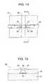
seat cushion 80 having still another variation of tuck-in groove, acushioning pad 81 has a tuck-ingroove 83 and invertedtrapezoidal grooves 86 across the tuck-ingroove 83 at locations where strip sections of a planarconductive film 82 is laid in the tuck-ingrooves 83. The invertedtrapezoidal groove 86 at opposite sides has an open top end flanked with a pair of rounded retainingprotrusions 87 at each of opposite sides of the tuck-ingroove 83. Each rounded retainingprotrusion 87 is formed as an integral portion of thecushioning pad 81. The strip section of the planarconductive film 82 is forced into the invertedtrapezoidal groove 86 passing through theretaining protrusions 87 and laid in the tuck-ingroove 83. - According to the tuck-in
groove 83 shown in Figures 14 and 15, the strip section of the planarconductive film 82 is prevented from coming up and out of the tuck-ingroove 83 by theretaining protrusions 87. While the tuck-ingroove 83 thus constructed is advantageous in preventing the planarconductive film 82 from being damaged or broken, and hence an electric disconnection of the electrically conductive element, nevertheless, the tuck-ingroove 83 inevitably reaches aggravation of setting easiness of the strip sections of the planarconductive film 82. That is, if theretaining protrusion 87 is made larger in order to prevent the strip section of the planarconductive film 82 from coming up and out of the tuck-ingroove 83, it becomes an onerous task to tuck the strip section of the planarconductive film 82 in the tuck-ingroove 83. - Another idea on eliminating an occurrence of breaking of an electrically conductive layer or film of a planar occupant sensor of a seat unit is disclosed in Japanese Unexamined Patent Publication No. 2000-318503. This planar occupant sensor has a protective sheet with an extension inserted between cushioning pad of a seatback and an adhesive layer so as to prevent the electrically conductive layer or film from breaking. However, the protection sheet is used only for protecting the electrically conductive layer or film. In addition, the electrically conductive layer or film is not laid in tuck-in grooves.
- It is an object of the present invention to provide a seat cushion for a vehicle seat unit of the type having a flexible but inelastic planar conductive film disposed between a cushioning pad with a plurality of tuck-in grooves and a seat covering and locally laid in the tuck-in grooves in which the flexible but inelastic planar conductive film is reinforced at locations where the flexible but inelastic planar conductive film traverses the tuck-in grooves so as to prevent an occurrence of what is called a pattern crack (an electric disconnection) due to breakage or damage of the flexible but inelastic planar conductive film.
- It is another object of the present invention to provide a seat cushion with a flexible but inelastic planar conductive film disposed between a cushioning pad with a plurality of tuck-in grooves and a seat covering and locally laid in the tuck-in grooves in which, when an external impact load is applied to the seat cushion, the flexible but inelastic planar conductive film causes widespread flexure in response to contraction of the cushioning pad and diminishes local slacks or inelastic bending of the flexible but inelastic planar conductive film laid in the tuck-in grooves consequently.
- It is a further object of the present invention to provide a seat cushion with a flexible but inelastic planar conductive film disposed between a cushioning pad with a plurality of tuck-in grooves and a seat covering and locally laid in the tuck-in grooves which can keeps an attractive appearance.
- The foregoing objects of the present invention are achieved by a seat cushion for a vehicle seat unit that comprises a cushioning pad such as an urethane foam, a seat covering such as a cloth seat covering or a leather seat covering with which the cushioning pad is upholstered, and a flexible but inelastic planar conductive element (which comprises a flexible and inelastic film and an electrically conductive element buried in the flexible and inelastic film and is hereafter referred to as a planer conductive film for simplicity) disposed between the cushioning pad and the seat covering. The cushioning pad has a plurality of generally U-shaped tuck-in grooves in which the seat covering is locally retained. The planer conductive element is locally made thicker for reinforcement than the remaining portion thereof at locations where the planar conductive element traverses the tuck-in grooves. The planar conductive film is such as to be used as a planar sensor device that detects presence of an occupant sitting on the seat cushion or an occupant such as an infant or a small child secured in a child safety seat on the seat cushion or as a planar seat heater.
- According to the seat cushion, the planar conductive film causes less local slacks or inelastic bending in the tuck-in grooves through the instrumentally of the reinforcement and sustains less breakage or damage. In consequence, the planar conductive film prevents the electrically conductive element buried in the film from sustaining what is called pattern cracks (electric disconnections). Even if the planar conductive film causes local slacks or inelastic bending in the tuck-in grooves when the seat cushion contracts due to an external impact force from above, the planar conductive film slides on the cushioning pad to produce widespread flexure over the entire area thereof, so that the local slacks or inelastic bending in the tuck-in grooves are dispersed through the flexure and then diminished. Since the tuck-in grooves are not crushed, the seat cushion keeps its attractive appearance.
- According to another aspect of the present invention, the planer conductive film is locally made more slippery and/or more elastic for reinforcement than the remaining portion thereof at locations where the planar conductive element traverses the tuck-in grooves. The planar conductive film at the slippery or elastic portions diminishes in frictional drag against the cushioning pad. The slippery or elastic portion is realized by fixing a segmental plastic piece made of polyethylene terephthalate or polyimide to the planar conductive film, or otherwise by thickening the planar conductive film so as to provide it locally with increased elasticity.
- The planar conductive film provided with reinforced portions made slippery or elastic is hardly bendable in the tuck-in grooves, so that the planar conductive film prevents the electrically conductive element buried in the film from sustaining what is called pattern cracks (electric disconnections) due to slacks or inelastic bending. In addition, even if the planar conductive film causes local slacks or inelastic bending in the tuck-in grooves when the seat cushion contracts due to an external impact force from above, the planar conductive film slides on the cushioning pad to produce widespread flexure over the entire area thereof, so that the local slacks or inelastic bending in the tuck-in grooves are dispersed through the widespread flexure of the planar conductive film and then diminished. Accordingly, the planar conductive film is protected against an electric disconnection without making the tuck-in grooves of the cushioning pad shallow or otherwise blocking portions of the tuck-in grooves crossed over by the planar conductive film.
- The reinforced portion may be formed by fixing a segmental plastic piece to either one or both of opposite surfaces of the planar conductive film. The segmental plastic piece is preferred to be made of polyethylene terephthalate or polyimide in light of thickness, slipping performance and elasticity.
- The reinforced portion may be formed in a lengthwise direction of the planer conductive film, in other words in a direction perpendicular to the tuck-in groove. The planar conductive film at the reinforced portions provides elasticity and restoration more effectively with respect to the tuck-in grooves, so as thereby to prevent the electrically conductive element from sustaining pattern cracks or electric disconnections.
- The planar conductive film at the reinforced portions may be provided with integrated tongues extending perpendicularly from opposite lengthwise sides of the planar conductive film, in other words in a lengthwise direction of the tuck-in groove. The planar conductive film at the reinforced portions is prevented from causing positional displacement due to increased thickness, enhanced slippage performance and elasticity when the seat cushion receives external impact force from above and, in consequence, provides positioning convenience.
- The planar conductive film may be used as a planar sensor device that detects an occupant condition, e.g. presence of an occupant or a commodity, occupant type and/or occupant location, in order to control actuation of, for example, an occupant associated protection system such as an air bag in response to a detected occupant condition. The planar sensor device includes a planar array of pressure sensors operative to turn conductive when receiving external impact force from above. The planar sensor device is prevented from causing a pattern crack or electric disconnection of the planar array of pressure sensors, the occupant protection system is appropriately controlled in actuation.
- The planar conductive film may be used as a planar seat heater. The planar seat heater is prevented from causing a pattern crack or electric disconnection of a heating wire.
- The above and other objects and features of the present invention will be clearly understood from the following detailed description when read with reference to the accompanying drawings, wherein the same numeral numbers have been used to denote same or similar parts or mechanisms throughout the drawings, and in which:
- Figure 1
- is a plan view of a seat cushion for a vehicle seat unit according to an embodiment of the present invention;
- Figure 2
- is a cross sectional view of a part of the seat cushion upholstered with a seat covering;
- Figure 3
- is a cross sectional view of a pressure sensor;
- Figure 4
- is an enlarge plan view of a part A of the seat cushion;
- Figure 5
- is a cross sectional view of Figure 4 taken along a line V-V;
- Figure 6
- is a perspective view of the part A of the seat cushion;
- Figures 7A to 7D
- are explanatory views of various reinforcement structures;
- Figure 8
- is an explanatory view of the seat cushion with an external load exerted thereon;
- Figure 9
- is a plan view of a seat cushion for a vehicle seat unit according to another embodiment of the present invention;
- Figure 10
- is a cross sectional view of a prior art seat cushion;
- Figure 11
- is an explanatory cross sectional view of the seat cushion of Figure 10 showing an appearance of damage of a planar conductive film;
- Figure 12
- is a cross sectional view of the prior art seat cushion in which a modified tuck-in grooves are provided;
- Figure 13
- is a cross sectional view of the prior art seat cushion in which an alternative tuck-in grooves are provided;
- Figure 14
- is a plan view of the prior art seat cushion in which a still alternative tuck-in grooves are provided; and
- Figure 15
- is a cross sectional view of the seat cushion of Figure 14 taken along a line XV-XV.
- Referring to the drawings in detail, and, in particular, to Figures 1 to 3 showing a
seat cushion 1 of a vehicle seat unit according to an embodiment of the present invention, theseat cushion 1 comprises anelastic cushioning pad 2 made of such as urethane, a patterned planarconductive film 8 that is flexible but inelastic and aseat covering 3. Theelastic cushioning pad 2 is formed as one integral piece and comprises three sections, namely aseat section 2A and twoside support sections 2B at opposite side of theseat section 2A. Theelastic cushioning pad 2 has a lengthwise tuck-ingroove 4 formed along a border between theseat section 2A and eachside support section 2B and two transverse tuck-ingrooves 5 formed in a central portion of the seat section and extending between the opposite lengthwise tuck-ingrooves 4. As shown in Figure 2,wires 6 are embedded below the respective tuck-ingrooves elastic cushioning pad 2. Thewires 6 has hooks 7 partly protruding into the tuck-ingrooves grooves seat cushion 1. - The patterned planer
conductive film 8 such as made of a synthetic resin film is comprised of a center lengthwisestrip section 8A, side lengthwisestrip sections 8B at centers of theside support sections 2B, a number oftransverse strip sections 8C connecting the side lengthwisestrip sections 8B to the center lengthwisestrip section 8A and abase section 8D at a front end of the center lengthwisestrip section 8A. The patterned planarconductive film 8 is provided with a plurality ofpressure sensors 10 buried in the lengthwise andtransverse strip sections controller 8D with a built-in microcomputer (not shown) buried in thebase section 8D. Eachpressure sensor 10 is electrically connected to thecontroller 8D. In other words, the patterned planarconductive film 8 is provided with a planar array ofpressure sensors 10 as an electrically conductive element buried therein. Eachpressure sensor 10 is turned conductive to provide for thecontroller 8D a signal when thecushioning pad 2 contracts due to an external impact force in such a manner as will be described later - As shown in Figure 3, the
pressure sensor 10 comprises upper and lower flexible electricallyconductive segments spacer blocks 14 that are disposed with a separation therebetween so as to provide aspace 13 between the upper and lower electricallyconductive segments conductive segments cover layers pressure sensor 10 to have a thickness between outer surfaces of the cover layers 15 and 16 of approximately 400 µm. As shown by an imaginary line in Figure 3, the upper and lower electricallyconductive segments controller 8D a signal when an external load is applied to thepressure sensor 10 from above. - Accordingly, the planar
conductive film 8 with a planar array ofpressure sensors 10 buried therein functions as a planar sensor device to detect an occupant condition, e.g. occupant type and/or occupant location, on the seat cushion. Thecontroller 8D controls actuation of an occupant associated protection system such as an air bag in response to a detected occupant condition represented by signals from the planar sensor device. - Figures 4 through 7 show an encircled part of the
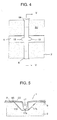
seat cushion 1 indicated by a circle A in Figure 1 where the center lengthwisestrip section 8A of the patterned planarconductive film 8 crosses over the transverse tuck-ingroove 5. The following description is true of thetransverse strip section 8C and the lengthwise tuck-ingroove 4. Theelastic cushioning pad 2 has a transverse tuck-ingroove 5 and a generally invertedtrapezoidal recess 17 across over the transverse tuck-ingroove 5. The generally invertedtrapezoidal recess 17 is comprised of aflat bottom wall 17a (which doubles part of a bottom 5a of the transverse tuck-in groove 5) andside walls 17b slanting outward in opposite transverse directions with respect to anupper surface 2U of thecushioning pad 2, respectively. - As shown in Figures 5 and 6, the
lengthwise strip section 8A of the patterned planarconductive film 8 is locally forced into the generally invertedtrapezoidal recess 17 and is then laid down on the bottom wall of the transverse tuck-ingroove 5. The patterned planarconductive film 8 has a pair oftongues 18 having a specified length which extend perpendicularly from opposite sides of eachstrip section groove 5. Further, the patterned planarconductive film 8 has a specified length of reinforcedportion 19 in each strip section that is forced in the generally invertedtrapezoidal recess 17 such as shown in Figures 7A through 7D. - Referring to Figure 7A showing a reinforced
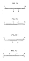
portion 19 of eachstrip section conductive film 8, the reinforcedportion 19 comprises apolyethylene terephthalate substrate 8a forming a part of the patterned planarconductive film 8 and a segmental reinforcingpiece 20 fixed to the back of thepolyethylene terephthalate substrate 8a. The reinforcedportion 19 is a portion of the patterned planarconductive film 8 that is laid in the generally invertedtrapezoidal recess 17 across over the transverse tuck-ingroove 5 with a specified thickness, an enhanced slipping performance and a sufficient elasticity. It is desirable for the segmental reinforcingpiece 20 to be made of plastic, or otherwise, polyethylene terephthalate or polyimide that satisfies the requirement that a segmental reinforcing piece is formed thin, slippery and elastic. - Referring to Figure 7B showing an integrated reinforced portion of the strip section of the patterned planar
conductive film 8, the reinforcedportion 19 comprises apolyethylene terephthalate substrate 8a forming a part of the patterned planarconductive film 8 and a segmental reinforcingpiece 20 fixed to the front of thePET substrate 8a. It is desirable for the segmental reinforcingpiece 20 to be made of plastic, or otherwise, polyethylene terephthalate or polyimide in light of providing a portion of the patterned planarconductive film 8 that is laid in the generally invertedtrapezoidal recess 17 across over the transverse tuck-ingroove 5 with a specified thickness, an enhanced slipping performance and a sufficient elasticity. - Referring to Figure 7C showing an integrated reinforced portion of the strip section of the patterned planar
conductive film 8, the reinforcedportion 19 comprises apolyethylene terephthalate substrate 8a having an integrated thickeningportion 21 at a back side of the patterned planarconductive film 8 that is laid in the generally invertedtrapezoidal recess 17 across over the transverse tuck-ingroove 5. - Referring to Figure 7D showing another reinforced portion of the strip section of the patterned planar
conductive film 8, the reinforcedportion 19 comprises apolyethylene terephthalate substrate 8a having an integrated thickeningportion 23 at front and back sides of the patterned planarconductive film 8 that is laid in the generally invertedtrapezoidal recess 17 across over the transverse tuck-ingroove 5. The patterned planarconductive film 8 has slant faces 22 between the integrated thickeningportion 23 and thepolyethylene terephthalate substrate 8a. - The integrated reinforced
portion 19 having the thickeningportion polyethylene terephthalate substrate 8a such as shown in Figure 7C or 7D satisfies the requirement because polyethylene terephthalate itself can be formed thin and slippery and has sufficient elasticity. The formation of thickening portion eliminates the process of fixing a segmental reinforcing piece to thepolyethylene terephthalate substrate 8a. - As was previously described, the patterned planar
conductive film 8 is laid between theelastic cushioning pad 2 and the seat covering 3 with the integrated reinforced portion laid in the transverse tuck-ingroove 5 as shown in Figure 5. While thesear cushion 1 is free of external impact force from above, the integrated reinforced portion of the patterned planarconductive film 8 lies along the bottom and slantedside walls seat cushion 1 experiences external impact force from above, while theelastic cushioning pad 2 is compressed, the patterned planarconductive film 8 is stretched outward as shown in Figure 8. Specifically, the patterned planarconductive film 8 slides on theupper surface 2U of thecushioning pad 2 with the integrated reinforced portion risen up to a state shown by a solid line passing through an interim state shown by an imaginary line. - According to the
seat cushion 1, when theseat cushion 1 repeatedly experiences external impact force from above, the patterned planarconductive film 8 except reinforced portions laid in the tuck-ingrooves conductive film 8 ends up with absorption of the slacks or inelastic bending through its overall area. As a result, the patterned planarconductive film 8 prevents an occurrence of breakage or damage, and hence an occurrence of an electrical disconnection (a pattern crack) of the conductive element resulting from the breakage or damage. - In a nutshell, the
seat cushion 1 shown by way of example in Figures 1 through 8 comprises thecushioning pad 2 with the lengthwise and transverse tuck-ingrooves conductive film 8 with a planar conductive element buried therein is embedded. The patterned planarconductive film 8 has the reinforcedportions 19 having an increased thickness that are laid in the lengthwise and transverse tuck-ingrooves conductive film 8 at the reinforcedportions 19 is resistant to bend and, consequently, prevented from causing an electric disconnection (a pattern crack). Further, even when the patterned planarconductive film 8 at the reinforced portions laid in the tuck-ingrooves conductive film 8 except the reinforced portions slides on thecushioning pad 2 and produces widespread flexure in response to the contraction of the cushioning pad and, in consequence, absorbs the slacks or inelastic bending through the widespread flexure. As a result, the patterned planarconductive film 8 prevents an occurrence of breakage or damage, and hence an occurrence of an electrical disconnection (a pattern crack) of the conductive element resulting from the breakage or damage. In addition, the tuck-ingrooves conductive film 8 locally therein, the seat cushion can be designed for improved attractive appearance. - In the case where the patterned planar
conductive film 8 has the reinforcedportions 19 having an integrated reinforced portion made more slippery and more elastic than the remaining portion thereof, the patternedplanar film 8 is hard to produce slacks or inelastic bending in the tuck-ingrooves conductive film 8 at the integrated reinforcedportions 19 prevents an occurrence of an electric disconnection (a pattern crack) of the electrically conductive element. Further, even when the patterned planarconductive film 8 at the integrated reinforced portions laid in the tuck-ingrooves seat cushion 1 due to external impact force, the planarconductive film 8 except the integrated reinforcedportions 19 slides on thecushioning pad 2 and produces widespread flexure in response to the contraction of thecushioning pad 1. As a result, the patterned planarconductive film 8 prevents an occurrence of breakage or damage, and hence an occurrence of an electrical disconnection (a pattern crack) of the electrically conductive element resulting from the breakage or damage. In addition, the tuck-ingrooves conductive film 8 locally therein, theseat cushion 1 can be designed for improved attractive appearance. - In the case where the planar
conductive film 8 is used as a planar sensor device operative to detect an occupant sitting on theseat cushion 1 or a child secured in a child safety seat put on theseat cushion 1, the planar sensor device can reliably control actuation of an occupant associated protection system. - The reinforced
portion 19 is formed by fixing a segmental reinforcingpiece 20 made of plastic to at least one of opposite surfaces of the planarconductive film 8. The segmental reinforcingpiece 20 is conveniently used to provide easily the planar conductive film with required thickness, slipping performance and elasticity locally. - Since the reinforced
portions 19 are formed in a lengthwise direction of the planerconductive film 8, in other words in a direction perpendicular to the tuck-ingrooves conductive film 8 at the reinforcedportions 19 provides elasticity and restoration ability more effectively with respect to the tuck-ingrooves - The planar
conductive film 8 used as a planar sensor device includes a planar array ofpressure sensors 10 operative to turn conductive when receiving external impact force from above. Specifically, thepressure sensor 10 comprises the upper and lower flexible electricallyconductive segments - The planar
conductive film 8 is provided withintegrated tongues 18 extending perpendicularly from opposite lengthwise sides of the reinforcedportion 19, in other words, in a lengthwise direction of the tuck-in groove. The planarconductive film 8 at the reinforced portions is prevented from causing positional displacement due to increased thickness, enhanced slippage performance and elasticity when the seat cushion receives external impact force from above and, in consequence, provides positioning convenience. - Figure 9 shows a
seat cushion 1 for a vehicle seat unit according to another embodiment of the present invention that is used as a planar seat heating film, theseat cushion 1 comprises anelastic cushioning pad 2 made of such as urethane, an seat covering (not shown) covering thecushioning pad 2, and a flexible butinelastic film 24 such as a polyethylene terephthalate film with a nichrome orheating wire 26 as an electrically conductive element buried in the flexible and inelastic film 24 (which is hereafter referred to as a planer conductive film for simplicity) that is disposed between thecushioning pad 2 and the seat covering. Theelastic cushioning pad 2 is formed as one integral piece and comprises three sections, namely aseat section 2A and twoside support sections 2B at opposite side of theseat section 2A. Theelastic cushioning pad 2 has a lengthwise tuck-ingroove 4 formed along a border between theseat section 2A and eachside support section 2B and two transverse tuck-ingrooves 5 formed in a central portion of the seat section and extending between the opposite lengthwise tuck-ingrooves 4 so as thereby to divide theseat section 2A into three sub-sections, namely front, center and rear sub-sections. - The planar
conductive film 24 is formed as one integral piece divided into three sections, namely front, center andrear sections seat section 2A, respectively. These front, center andrear sections side strips 24A extending across over the transverse tuck-ingrooves 5. Theheating wire 26 runs meandering in therespective sub-sections conductive film 24 and is electrically connected to aconnector 25 disposed at a front end of thefront sub-section 24F thereof. Theheating wire 26 is supplied with electric power from power supply means such as a battery installed in the vehicle through theconnector 25 to generate heat. - Each of the side strips 24A, that is laid in the transverse tuck-in
groove 5, is formed as the same in structure as the integrated reinforcedportion 19 of the patterned planar conductive film 8 (se Figures 7A to 7D) of the previous embodiment. Thecushioning pad 2 may be preferably provided with a generally inverted trapezoidal recess extending across over the transverse tuck-ingroove 5 such as shown in Figure 5 in which theside strip 24A of the planarconductive film 24 is laid. - According to the planar
conductive film 24 formed as a planar seat heater, theheating wire 26 is prevented from causing an electric disconnection due to an occurrence of breakage or damage of the planarconductive film 24. - The present invention has been described with reference to preferred embodiments thereof. However, it will be appreciated that variants and other embodiments can be effected by person of ordinary skill in the art without departing from the scope of the invention.
Claims (8)
- A seat cushion (1) for a vehicle seat unit comprising a cushioning pad (2), a seat covering (3) with which said cushioning pad (2) is upholstered and planar conductive means (8; 24) with an electrically conductive element buried therein that is disposed between said cushioning pad (2) and said seat covering (3), characterized in that;
said cushioning pad (2) has a plurality of tuck-in grooves (4, 5) in which said seat covering (3) is locally retained and said planer conductive means (8; 24) is reinforced at portions (19) that traverse said tuck-in grooves (4, 5). - A seat cushion as defined in claim 1, characterized in that said reinforced portions (19) are thicker than the remaining portion thereof.
- A seat cushion as defined in claim 1, characterized in that said reinforced portions (19) are more slippery or more elastic than the remaining portion thereof.
- A seat cushion as defined in any one of said preceding claims 1 to 3, characterized in that said planar conductive means (8) comprises a planar sensor device (10) operates to detect an occupant sitting on said seat cushion.
- A seat cushion as defined in any one of said preceding claims 1 to 4, characterized in that each said reinforced portion (19) is formed by a segmental reinforcement (20) fixed to at least one of opposite sides of said planar conductive means (8, 24).
- A seat cushion as defined in any one of said preceding claims 1 to 5, characterized in that each said reinforced portion (19) is formed in a direction perpendicular to said tuck-in groove (4, 5).
- A seat cushion as defined in claim 4, characterized in that said planar sensor device comprises a planar array of pressure sensors (10) operative, each said pressure sensor (10) comprising upper and lower electrically conductive segments (11, 12) that are brought into contact with each other when said pressure sensor (10) receives an external load from above.
- A seat cushion as defined in any one of said preceding claims 1 to 7, characterized in that said planar conductive means (8) is provided with a pair of integrated tongues (18) that extend in a direction of said tuck-in groove (4, 5) from opposite sides of said planar conductive means (8), respectively, at a location where said planar conductive means (8) transverse said tuck-in groove (4, 5).
Applications Claiming Priority (2)
| Application Number | Priority Date | Filing Date | Title |
|---|---|---|---|
| JP2002102638A JP4000886B2 (en) | 2002-04-04 | 2002-04-04 | Vehicle seat device |
| JP2002102638 | 2002-04-04 |
Publications (2)
| Publication Number | Publication Date |
|---|---|
| EP1356983A1 true EP1356983A1 (en) | 2003-10-29 |
| EP1356983B1 EP1356983B1 (en) | 2007-06-27 |
Family
ID=28786271
Family Applications (1)
| Application Number | Title | Priority Date | Filing Date |
|---|---|---|---|
| EP03007682A Expired - Lifetime EP1356983B1 (en) | 2002-04-04 | 2003-04-03 | Seat cushion for vehicle seat unit |
Country Status (4)
| Country | Link |
|---|---|
| US (1) | US6953224B2 (en) |
| EP (1) | EP1356983B1 (en) |
| JP (1) | JP4000886B2 (en) |
| DE (1) | DE60314561T2 (en) |
Cited By (6)
| Publication number | Priority date | Publication date | Assignee | Title |
|---|---|---|---|---|
| FR2870488A1 (en) * | 2004-05-21 | 2005-11-25 | Faurecia Sieges Automobile | MOTOR VEHICLE SEAT COMPRISING A FLEXIBLE COMPONENT FIXED ON A SEAT MAINASSURE, UNDER THE GARAGE COIFFE |
| FR2870798A1 (en) * | 2004-05-27 | 2005-12-02 | Faurecia Sieges Automobile | MOTOR VEHICLE SEAT COMPRISING A FLEXIBLE SOAP ADAPTED ON A SEAT MAILING UNDER THE GARAGE COIFFE |
| WO2008039268A1 (en) * | 2006-09-27 | 2008-04-03 | Illinois Tool Works Inc. | Seat heater with occupant sensor |
| EP2000355A1 (en) * | 2007-06-07 | 2008-12-10 | IEE INTERNATIONAL ELECTRONICS & ENGINEERING S.A. | Vehicle seat |
| WO2008145671A3 (en) * | 2007-05-29 | 2009-03-05 | Iee Sarl | Upholstered seat element |
| US8052212B2 (en) | 2005-09-08 | 2011-11-08 | Iee International Electronics & Engineering S.A. | Seat foam with sensor mat |
Families Citing this family (23)
| Publication number | Priority date | Publication date | Assignee | Title |
|---|---|---|---|---|
| DE102005056882B4 (en) * | 2005-01-24 | 2012-06-14 | F.S. Fehrer Automotive Gmbh | Motor vehicle seat with occupant detector |
| DE102006031899B3 (en) * | 2006-04-20 | 2007-06-21 | W.E.T. Automotive Systems Ag | Interior component e.g. seat, surface air conditioning system for motor vehicle, has coating layer that is connected with air conditioning layer such that insertion case is formed, and detector device that is inserted into case |
| US7823972B2 (en) * | 2006-11-01 | 2010-11-02 | Gm Global Technology Operations, Inc. | Recliner adjustment utilizing active material sensors |
| US20080136227A1 (en) * | 2006-12-11 | 2008-06-12 | 3M Innovative Properties Company | Vehicle seat sensor assembly |
| BR112012018816B1 (en) | 2009-12-21 | 2021-07-27 | Aisin Seiki Kabushiki Kaisha | SEAT CUSHION FOR A VEHICLE SEAT AND METHOD FOR MOUNTING A LOAD DETECTION DEVICE |
| JP5488167B2 (en) * | 2010-04-26 | 2014-05-14 | アイシン精機株式会社 | Load detector mounting structure |
| JP5509836B2 (en) * | 2009-12-21 | 2014-06-04 | アイシン精機株式会社 | Load detection device mounting structure, cushion member and seat device provided with the load detection device |
| JP5573185B2 (en) * | 2010-01-19 | 2014-08-20 | トヨタ紡織株式会社 | Vehicle seat |
| JP5495067B2 (en) * | 2010-08-06 | 2014-05-21 | 株式会社デンソー | Occupant detection sensor and manufacturing method thereof |
| JP5673095B2 (en) * | 2010-12-28 | 2015-02-18 | トヨタ紡織株式会社 | Vehicle seat |
| CN103097184B (en) * | 2011-03-07 | 2016-01-20 | 松下知识产权经营株式会社 | Seat heaters for vehicles |
| JP5668594B2 (en) * | 2011-04-28 | 2015-02-12 | トヨタ紡織株式会社 | Vehicle seat |
| JP2012250662A (en) * | 2011-06-06 | 2012-12-20 | Toyota Boshoku Corp | Vehicle seat |
| US8507102B1 (en) | 2012-08-07 | 2013-08-13 | Fownes Brothers & Co., Inc. | Conductive leather materials and methods for making the same |
| JP5960545B2 (en) * | 2012-08-13 | 2016-08-02 | テイ・エス テック株式会社 | Vehicle seat |
| JP6024528B2 (en) * | 2013-03-08 | 2016-11-16 | 株式会社デンソー | Mounting structure of load detection device for passenger seating detection |
| JP2014201244A (en) | 2013-04-08 | 2014-10-27 | 三菱自動車工業株式会社 | Vehicular seat |
| JP5550762B1 (en) * | 2013-05-01 | 2014-07-16 | 株式会社 ミッドフィルダー | Massage mat and bed |
| US10221519B2 (en) | 2014-12-10 | 2019-03-05 | Fownes Brothers & Co., Inc. | Water-repellant conductive fabrics and methods for making the same |
| WO2016158758A1 (en) * | 2015-03-27 | 2016-10-06 | テイ・エス テック株式会社 | Seat with detector |
| US20170291518A1 (en) * | 2016-04-06 | 2017-10-12 | Magna Seating Inc. | Capacitive Sensing Antenna Array |
| JP2018075872A (en) * | 2016-11-07 | 2018-05-17 | テイ・エス テック株式会社 | Vehicle seat |
| JP2018052498A (en) * | 2018-01-10 | 2018-04-05 | テイ・エス テック株式会社 | Vehicle seat |
Citations (3)
| Publication number | Priority date | Publication date | Assignee | Title |
|---|---|---|---|---|
| JPH10329597A (en) * | 1997-05-29 | 1998-12-15 | Ikeda Bussan Co Ltd | Seating sensor arrangement structure of seat |
| JP2000318503A (en) | 1999-05-11 | 2000-11-21 | Honda Motor Co Ltd | Mounting structure of occupant detection sensor |
| JP2002065396A (en) * | 2000-08-31 | 2002-03-05 | Daihatsu Motor Co Ltd | Vehicle seating sensor arrangement structure |
Family Cites Families (6)
| Publication number | Priority date | Publication date | Assignee | Title |
|---|---|---|---|---|
| US4242672A (en) * | 1977-11-09 | 1980-12-30 | Gault Robert L | Patient monitoring system and switch |
| JP2909961B2 (en) * | 1996-05-29 | 1999-06-23 | アイシン精機株式会社 | Seating detection device |
| JPH1134710A (en) * | 1997-07-24 | 1999-02-09 | Bridgestone Corp | Seat with seating sensor |
| US6108842A (en) * | 1998-06-29 | 2000-08-29 | Lear Automotive Dearborn, Inc. | Vehicular seat assembly having a flexible air bag suppression sensor apparatus and method of installing the flexible air bag suppression sensor apparatus |
| JP3726555B2 (en) * | 1999-05-18 | 2005-12-14 | 日産自動車株式会社 | Pressure sensor unit for seat |
| JP4356243B2 (en) * | 2001-01-12 | 2009-11-04 | 株式会社デンソー | Mounting structure for occupant seating sensor |
-
2002
- 2002-04-04 JP JP2002102638A patent/JP4000886B2/en not_active Expired - Fee Related
-
2003
- 2003-04-03 EP EP03007682A patent/EP1356983B1/en not_active Expired - Lifetime
- 2003-04-03 DE DE60314561T patent/DE60314561T2/en not_active Expired - Lifetime
- 2003-04-03 US US10/405,938 patent/US6953224B2/en not_active Expired - Fee Related
Patent Citations (3)
| Publication number | Priority date | Publication date | Assignee | Title |
|---|---|---|---|---|
| JPH10329597A (en) * | 1997-05-29 | 1998-12-15 | Ikeda Bussan Co Ltd | Seating sensor arrangement structure of seat |
| JP2000318503A (en) | 1999-05-11 | 2000-11-21 | Honda Motor Co Ltd | Mounting structure of occupant detection sensor |
| JP2002065396A (en) * | 2000-08-31 | 2002-03-05 | Daihatsu Motor Co Ltd | Vehicle seating sensor arrangement structure |
Non-Patent Citations (3)
| Title |
|---|
| PATENT ABSTRACTS OF JAPAN vol. 1999, no. 03 31 March 1999 (1999-03-31) * |
| PATENT ABSTRACTS OF JAPAN vol. 2000, no. 14 5 March 2001 (2001-03-05) * |
| PATENT ABSTRACTS OF JAPAN vol. 2002, no. 07 3 July 2002 (2002-07-03) * |
Cited By (10)
| Publication number | Priority date | Publication date | Assignee | Title |
|---|---|---|---|---|
| FR2870488A1 (en) * | 2004-05-21 | 2005-11-25 | Faurecia Sieges Automobile | MOTOR VEHICLE SEAT COMPRISING A FLEXIBLE COMPONENT FIXED ON A SEAT MAINASSURE, UNDER THE GARAGE COIFFE |
| FR2870798A1 (en) * | 2004-05-27 | 2005-12-02 | Faurecia Sieges Automobile | MOTOR VEHICLE SEAT COMPRISING A FLEXIBLE SOAP ADAPTED ON A SEAT MAILING UNDER THE GARAGE COIFFE |
| US8052212B2 (en) | 2005-09-08 | 2011-11-08 | Iee International Electronics & Engineering S.A. | Seat foam with sensor mat |
| WO2008039268A1 (en) * | 2006-09-27 | 2008-04-03 | Illinois Tool Works Inc. | Seat heater with occupant sensor |
| US7500536B2 (en) | 2006-09-27 | 2009-03-10 | Illinois Tool Works Inc. | Seat heater with occupant sensor |
| WO2008145671A3 (en) * | 2007-05-29 | 2009-03-05 | Iee Sarl | Upholstered seat element |
| CN101678786B (en) * | 2007-05-29 | 2012-06-13 | Iee国际电子工程股份公司 | Upholstered seat element |
| US8511754B2 (en) | 2007-05-29 | 2013-08-20 | Iee International Electronics & Engineering S.A. | Upholstered seat element |
| EP2000355A1 (en) * | 2007-06-07 | 2008-12-10 | IEE INTERNATIONAL ELECTRONICS & ENGINEERING S.A. | Vehicle seat |
| WO2008148713A3 (en) * | 2007-06-07 | 2009-04-09 | Iee Sarl | Vehicle seat |
Also Published As
| Publication number | Publication date |
|---|---|
| US6953224B2 (en) | 2005-10-11 |
| JP2003291708A (en) | 2003-10-15 |
| EP1356983B1 (en) | 2007-06-27 |
| JP4000886B2 (en) | 2007-10-31 |
| DE60314561D1 (en) | 2007-08-09 |
| US20030214161A1 (en) | 2003-11-20 |
| DE60314561T2 (en) | 2008-02-28 |
Similar Documents
| Publication | Publication Date | Title |
|---|---|---|
| EP1356983B1 (en) | Seat cushion for vehicle seat unit | |
| JP4362786B2 (en) | Capacitance sensor for film seating detection | |
| US7500536B2 (en) | Seat heater with occupant sensor | |
| US6906293B2 (en) | Combined sensor and heating element | |
| EP1931535B1 (en) | Seat foam with sensor mat | |
| JP6024528B2 (en) | Mounting structure of load detection device for passenger seating detection | |
| JP2010125121A (en) | Cushion body for vehicle seat | |
| WO2008145671A2 (en) | Upholstered seat element | |
| EP2000355A1 (en) | Vehicle seat | |
| JP2005508793A5 (en) | ||
| JP5561398B2 (en) | Vehicle seat cushion | |
| JP2012076547A (en) | Vehicular seat heater and vehicular seat | |
| JP3735679B2 (en) | Seat detection device for automobile seats | |
| JP2004528219A (en) | Detector for car seat | |
| KR102037836B1 (en) | Heating pad used in seat for vehicle and method for manufacturing thereof | |
| US5287572A (en) | Lever supporting system for foam mattress | |
| JP2011131857A (en) | Vehicular seat heater and vehicular seat | |
| KR101407742B1 (en) | Structure for attaching load detecting device and sheet device | |
| JP5577744B2 (en) | Load detection device for vehicle seat | |
| KR20070116978A (en) | Sensor assembly and its formation method | |
| JP5490375B2 (en) | Mat body | |
| JPH0419752Y2 (en) | ||
| JP3515715B2 (en) | Vehicle laying mat | |
| JP3946585B2 (en) | Control box and input / output device | |
| JP2003212018A (en) | Antenna unit for electric field detection type seat sensor |
Legal Events
| Date | Code | Title | Description |
|---|---|---|---|
| PUAI | Public reference made under article 153(3) epc to a published international application that has entered the european phase |
Free format text: ORIGINAL CODE: 0009012 |
|
| AK | Designated contracting states |
Kind code of ref document: A1 Designated state(s): AT BE BG CH CY CZ DE DK EE ES FI FR GB GR HU IE IT LI LU MC NL PT RO SE SI SK TR |
|
| AX | Request for extension of the european patent |
Extension state: AL LT LV MK |
|
| 17P | Request for examination filed |
Effective date: 20040323 |
|
| AKX | Designation fees paid |
Designated state(s): DE FR GB |
|
| GRAP | Despatch of communication of intention to grant a patent |
Free format text: ORIGINAL CODE: EPIDOSNIGR1 |
|
| GRAS | Grant fee paid |
Free format text: ORIGINAL CODE: EPIDOSNIGR3 |
|
| GRAA | (expected) grant |
Free format text: ORIGINAL CODE: 0009210 |
|
| AK | Designated contracting states |
Kind code of ref document: B1 Designated state(s): DE FR GB |
|
| REG | Reference to a national code |
Ref country code: GB Ref legal event code: FG4D |
|
| REF | Corresponds to: |
Ref document number: 60314561 Country of ref document: DE Date of ref document: 20070809 Kind code of ref document: P |
|
| EN | Fr: translation not filed | ||
| PLBE | No opposition filed within time limit |
Free format text: ORIGINAL CODE: 0009261 |
|
| STAA | Information on the status of an ep patent application or granted ep patent |
Free format text: STATUS: NO OPPOSITION FILED WITHIN TIME LIMIT |
|
| 26N | No opposition filed |
Effective date: 20080328 |
|
| PG25 | Lapsed in a contracting state [announced via postgrant information from national office to epo] |
Ref country code: FR Free format text: LAPSE BECAUSE OF FAILURE TO SUBMIT A TRANSLATION OF THE DESCRIPTION OR TO PAY THE FEE WITHIN THE PRESCRIBED TIME-LIMIT Effective date: 20080222 |
|
| GBPC | Gb: european patent ceased through non-payment of renewal fee |
Effective date: 20080403 |
|
| PG25 | Lapsed in a contracting state [announced via postgrant information from national office to epo] |
Ref country code: GB Free format text: LAPSE BECAUSE OF NON-PAYMENT OF DUE FEES Effective date: 20080403 |
|
| PGFP | Annual fee paid to national office [announced via postgrant information from national office to epo] |
Ref country code: DE Payment date: 20110330 Year of fee payment: 9 |
|
| REG | Reference to a national code |
Ref country code: DE Ref legal event code: R119 Ref document number: 60314561 Country of ref document: DE Effective date: 20121101 |
|
| PG25 | Lapsed in a contracting state [announced via postgrant information from national office to epo] |
Ref country code: DE Free format text: LAPSE BECAUSE OF NON-PAYMENT OF DUE FEES Effective date: 20121101 |