EP1356902A1 - Elektrisch angetriebenes Rundmesser - Google Patents
Elektrisch angetriebenes Rundmesser Download PDFInfo
- Publication number
- EP1356902A1 EP1356902A1 EP03005356A EP03005356A EP1356902A1 EP 1356902 A1 EP1356902 A1 EP 1356902A1 EP 03005356 A EP03005356 A EP 03005356A EP 03005356 A EP03005356 A EP 03005356A EP 1356902 A1 EP1356902 A1 EP 1356902A1
- Authority
- EP
- European Patent Office
- Prior art keywords
- blade housing
- bearing surface
- scoring
- blade
- head member
- Prior art date
- Legal status (The legal status is an assumption and is not a legal conclusion. Google has not performed a legal analysis and makes no representation as to the accuracy of the status listed.)
- Granted
Links
- 235000013372 meat Nutrition 0.000 description 5
- 238000010276 construction Methods 0.000 description 4
- 230000002093 peripheral effect Effects 0.000 description 4
- 238000005520 cutting process Methods 0.000 description 3
- 239000000314 lubricant Substances 0.000 description 3
- 238000005461 lubrication Methods 0.000 description 3
- 210000000988 bone and bone Anatomy 0.000 description 2
- 230000007246 mechanism Effects 0.000 description 2
- 230000004075 alteration Effects 0.000 description 1
- 229910052782 aluminium Inorganic materials 0.000 description 1
- XAGFODPZIPBFFR-UHFFFAOYSA-N aluminium Chemical compound [Al] XAGFODPZIPBFFR-UHFFFAOYSA-N 0.000 description 1
- 238000005266 casting Methods 0.000 description 1
- 244000145845 chattering Species 0.000 description 1
- 210000002808 connective tissue Anatomy 0.000 description 1
- 238000012423 maintenance Methods 0.000 description 1
- 229910052751 metal Inorganic materials 0.000 description 1
- 239000002184 metal Substances 0.000 description 1
- 238000000034 method Methods 0.000 description 1
- 238000012986 modification Methods 0.000 description 1
- 230000004048 modification Effects 0.000 description 1
- 230000008569 process Effects 0.000 description 1
- 229910001220 stainless steel Inorganic materials 0.000 description 1
- 239000010935 stainless steel Substances 0.000 description 1
Images


Classifications
-
- B—PERFORMING OPERATIONS; TRANSPORTING
- B26—HAND CUTTING TOOLS; CUTTING; SEVERING
- B26B—HAND-HELD CUTTING TOOLS NOT OTHERWISE PROVIDED FOR
- B26B25/00—Hand cutting tools involving disc blades, e.g. motor-driven
- B26B25/002—Motor-driven knives with a rotating annular blade
Definitions
- the present invention relates to a power operated rotary knife with an improved blade housing and clamping assembly.
- Power operated rotary knives have been used in commercial meat processing operations to trim fat and connective tissue from meat, trim pieces of met from bones, and to produce meat slices. Such knives are often constructed so that they are driven via a long flexible drive shaft. The knife operator wields the knife relatively freely at a meat cutting work station that is remote from the driving motor.
- a clamping assembly is used to secure the blade housing to a head member of the knife.
- the clamping assembly includes a clamp body and a pair of clamping screws.
- the pair of clamping screws extend through holes in the head member and into tapped holes in the clamp body. The clamping screws are tightened to secure the blade housing to the head member.
- the blade housing includes a slot on its outer periphery to facilitate remove of the blade from the blade housing without the necessity of removing the blade housing or the clamp body from the head member.
- the clamping screw nearest the blade housing slot is slightly loosened, a screwdriver is inserted in the slot and levered against the head member to resiliently expand the blade housing diameter and, thereby, release the blade from the blade housing.
- the screwdriver is removed from the slot and the blade housing returns to its unexpanded diameter and the clamping screw is tightened. Frictional forces between the blade housing, clamp body and head member maintain the blade housing in its unexpanded condition.
- the present invention provides for an improved rotary knife comprising an annular blade, a split blade housing for supporting the blade for rotation, a handle assembly including a head member for supporting the split blade housing, and a clamping assembly including a clamp body for clamping the split blade housing to the head member.
- a portion of the split blade housing is provided with an area of scoring along a bearing surface that bears against the clamp body.
- the clamp body is provided with an area of scoring along a bearing surface that bears against the blade housing bearing surface.
- the areas of scoring coact to inhibit movement of one end of the split blade housing with respect to a second end of the split blade housing when the split blade housing is clamped to the head member.
- the scoring of the clamp bearing surface of the blade housing comprises lines of scoring defining a pattern of alternating ridges and grooves and the scoring of the blade housing bearing surface of the clamp body comprises lines of scoring defining a pattern of alternating ridges and grooves.
- the lines of scoring of the blade housing are configured to inter fit with the lines of scoring of the clamp body, that is, the ridges of the clamp body engage the grooves of the blade housing and the ridges of the blade housing engage the grooves of the clamp body to increase the frictional force between the clamp body and the blade housing.
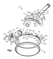
- a rotary knife 10 embodying the invention is illustrated in the drawings.
- the knife 10 comprises a handle 12, a generally circular, split blade housing 14 supported by the handle assembly 12, and an annular blade 18 supported by the blade housing 14 for rotation about a central axis.
- the illustrated knife is connected to a remote electric motor by a flexible drive shaft so that the blade 18 is driven from the electric motor.
- the motor and drive shaft may be of any suitable or conventional construction and are not illustrated. It should be appreciated that other means may be employed to drive the blade 18.
- an air motor may be mounted in the handle assembly 12 and connected to a source of pressurized air via a suitable hose, or an electric motor may be mounted in the handle assembly 12 and connected to a power source by a power cord.
- the frame member 20 rigidly supports the head assembly 24, a blade driving pinion gear 27 and a pinion gear supporting bearing 27a while providing a channel through which the flex shaft (not shown) extends to make a driving connection with the pinion gear 27.
- the head assembly 24 secures the blade housing 14 and the blade 18 to the housing while enabling their removal and replacement when desired.
- the illustrated head assembly 24 comprises a head member 40 and a clamp assembly 42 that detachably clamps the blade housing 14 and the blade 18 to the head member 40.
- the head assembly 24 also includes a conventional lubrication system (not shown) by which a relatively viscous, edible lubricant may be supplied to the pinion gear 27, the blade 18 and the blade housing 14 via suitable passages.
- the lubrication system forms no part of the invention and is therefore not described in further detail since it may be of any conventional or suitable construction and may be omitted from the knife 10 altogether if desired.
- the head member 40 positions the blade housing 14 relative to the handle assembly 12.
- the illustrated head member 40 is a generally crescent shaped, cast metal body that defines a semicircular blade housing seating region, a clamp assembly receiving, socket-like cavity 52, and a boss 54 that surrounds the frame member 20 and projects from the head member body opposite to the cavity 52 and seating region 50.
- the pinion gear bearing 27a is a tubular member that is fixed in the head member 40 and surrounds a shank of the pinion gear.
- the clamp assembly 42 includes a steeling mechanism 70 by which the blade 18 can be straightened by a knife operator. The steeling mechanism forms no part of the invention and is therefore not described in further detail since it may be of any conventional or suitable construction and may be omitted from the knife 10 altogether if desired.
- the clamp assembly 42 firmly maintains the blade housing 14 seated against the seating region 50 to rigidly position the blade 18 while covering the pinion gear 27 which might otherwise be directly exposed to meat, fat, bone chips, etc.
- the clamp assembly 42 comprises a clamp body 60 and clamping screws 62a, 62b.
- the clamp body 60 defines a semicircular recess 64 ( Figures 7 and 8) confronting the head member 40 for receiving the pinion gear 27, outer peripheral bearing surfaces 66a, 66b ( Figures 7 and 8) that engage the blade housing 14 along inner peripheral bearing surfaces 67a, 67b ( Figures 1, 2, 3 and 5) on respective opposite sides of the blade housing split 84, and clamping screw receiving bosses 68a, 68b ( Figure 7) that project past the blade housing 14 into the cavity 52.
- the clamping screws 62a, 62b extend through respective holes 69a, 69b in the rear side of the head member 40 and into respective tapped holes 70a, 70b ( Figure 7) in the clamp body bosses 68a, 68b.
- the screws 62a, 62b are tightened to clamp the clamp body 60 against the blade housing 14.
- Each clamp face 66a, 66b exerts force on the blade housing bearing surfaces 67a, 67b that depends on the tension in the respective clamping screws 62a, 62b.
- the illustrated clamping screws 62a, 62b are unscrewed from the clamp body 60 to release the clamp body 60 and the blade housing 14 from the handle assembly 12.
- the screws 62a, 62b and head member holes 69a, 69b are preferably constructed so that the screws 62a, 62b are captured in the holes 69a, 69b when unscrewed from the clamp body 60. This prevents the screws 62a, 62b from being misplaced when changing the blade housing 14.
- the blade 18 may be removed and replaced without the necessity of removing the blade housing 14.
- the blade housing 14 has first and second end portions 80, 82 extending circumferentially away from opposite sides of the blade housing split 84 along the handle seating region 50 and defines a radially inwardly opening circumferential groove 86 (best seen in Figure 3) that receives the blade 18.
- the blade housing 14 is split to enable resilient expansion for removing and replacing the blade 18.
- the blade housing 14 is constructed and arranged so that the end portion 82 is shiftable along the handle seating region 50 relative to the end portion 80 for expanding the blade housing 14.
- the blade housing 14 is centered on the axis of rotation of the blade 18 with the end portions 80, 82 forming a blade housing mounting structure that extends circumferentially partially about the blade housing 14 on opposite sides of the split 84 between the head member 40 and the clamp assembly 42.
- the illustrated end portions 80, 82 include axial extensions 92, 94 that are clamped between the clamp body 60 and the head member 40 and are construction for facilitating blade housing expansion for blade removal and replacement.
- the extension 92 defines an arcuate notch 96 through which the clamp body boss 68a extends.
- the notch 96 closely conforms to the shape of the boss 68a.
- the blade housing extension 94 defines an elongated reduced height section 98 that extends away from the split 84.
- the boss 68b extends through the reduced height section 98 when the blade housing 14 is supported on the head member 40.
- the length of the reduced height portion 98 assures that the blade housing end portion 82 can move freely along the confronting clamp face 66b toward and away from the end portion 80 when the clamp screw 62b is completely loosened.
- the blade housing 14 is formed with an expansion structure 120 that enables the housing 14 to be resiliently expanded, while still connected to the head member 40, when the blade 18 is removed and replaced.
- the expansion structure 120 comprises one or more, e.g., two spaced apart axial slots 122, 124 in the blade housing outer periphery 126 adjacent the head member 40.
- the clamping screw 62b is partially, but not completely loosened, thus maintaining some tension in the clamping screw 62b and, therefore, some clamping force applied to the blade housing 14.
- a screwdriver, or equivalent tool is inserted in the slot 124 and levered against the head member 40 to resiliently expand the blade housing diameter.
- the screwdriver is then removed from slot 124 and inserted in slot 122 and levered against the head member to further resiliently expand the blade housing diameter and allow for easy removal of the blade 18 from the blade housing groove 86. Because the clamping screw 62b is only partially loosened and some clamping force on the blade housing 14 remains, the blade housing 14 does not snap back or return to its unexpanded diameter when the screwdriver is removed from the slot 124 and inserted in slot 122. Similarly, the residual clamping force prevents the blade housing 14 from returning to its unexpanded diameter when the screw drive is removed from the slot 122.
- the screwdriver is used inserted in slot 122 and then slot 124 to urge the blade housing 14 back to its unexpanded diameter.
- the clamping screw 62b is then tightened to complete the blade replacement process.
- the blade housing end portion 82 is not similarly constrained and the blade housing end portion 82 may move with respect to the blade housing end portion 80, the clamp body 60 and the head member 40 if the blade housing 14 is subjected to enough force tending to expand its diameter, that is a force on the blade housing 14 that would tend to enlarge the size of the split 84.
- the threaded holes 70a, 70b of the clamp body 50 and the threads of the clamping screws 62a, 62b can only tolerate limited amount of tightening tension before failing.
- tightening the clamping screws 62a, 62b requires the operator to use a screwdriver on the screws. Some operators may not be able to tighten the screws to recommended torque values.
- the blade housing 14 and the clamp body 60 include structure for increasing the frictional force between the blade housing and the clamp body for any given tension or tightness of the clamping screws 68a, 68b.
- the structure includes an area of scoring 140 on the blade housing bearing surface 67b and a corresponding area of scoring 142 on the clamp body bearing surface 70b.
- the scoring areas 140, 142 comprise a plurality of parallel lines of scoring, the lines oriented being perpendicular to a direction of movement M ( Figure 5) of the blade housing end portion 82.
- the clamp body 60 is an aluminum casting. while the blade housing 14 is fabricated of stainless steel.
- the lines of scoring may easily be implemented by laser scoring. Desirably, the lines of the scoring in the respective scoring areas 140, 142 are sized and configured to inter fit to increase frictional forces.
- the scoring 140 of the blade housing bearing surface 67b comprises a series of radial grooves (shown schematically as 150a, 150b, 150c in Figure 6), when viewed in cross section, having a depth d1 of 0.005 inches, a width w1 of 0.020 inches and a distance r1 between adjacent grooves of 0.010 inches, while the scoring of the clamp body bearing surface 66b comprises a series of radial grooves (shown schematically as 152a, 152b, 152c in Figure 9), when viewed in cross section, having a depth d2 of 0.005 inches, a width w2 of 0.010 inches and a distance r2 between adjacent grooves of 0.020 inches.
- the areas of scoring may be viewed as an alternating pattern of grooves and ridges (distance between adjacent grooves).
- the grooves 150a, 150b, 150c of the blade housing bearing surface 67b width 0.020 inches
- the grooves 152a, 152b, 152c of the clamp body bearing surface 66b (width 0.010 inches) inter fit with the ridges 151a, 151b, 151c of the blade housing bearing surface (width 0.010 inches).
- a longitudinal extent of the areas of scoring 140, 142 is determined by a distance between an edge of the end portion 154 ( Figure 3) were the scoring area 140 commences and the outer edge 156 ( Figure 7) of the clamp body 60.
- the longitudinal extent of the areas of scoring 140, 142 is approximately 1 5/8 inches.
- areas of scoring 160, 162 between an outer peripheral bearing surface 180 of the end portion 82 of the blade housing 14 and the corresponding bearing surface 190 of the head member 40 may be provided. This is shown as an alternate embodiment in Figure 10. Such scoring areas 160, 162 of the outer peripheral bearing surface 180 of the blade housing 14 and the bearing surface 190 of the head member 170 respectively may be in addition to or in lieu of the areas of scoring 140, 142, shown in Figures 1-9.
- the areas of scoring 140, 142 are used because it is recognized that, over long usage of the knife 10, the lines of scoring will become worn. When the lines of scoring are worn, the respective components will need to be replaced. It is more economical to replace that blade housing 14 and the clamp body 60, than to replace the blade housing 14 and the head member 40.
Landscapes
- Life Sciences & Earth Sciences (AREA)
- Forests & Forestry (AREA)
- Engineering & Computer Science (AREA)
- Mechanical Engineering (AREA)
- Knives (AREA)
- Details Of Cutting Devices (AREA)
- Harvester Elements (AREA)
Applications Claiming Priority (2)
| Application Number | Priority Date | Filing Date | Title |
|---|---|---|---|
| US128001 | 1980-03-07 | ||
| US10/128,001 US6662452B2 (en) | 2002-04-22 | 2002-04-22 | Power operated rotary knife |
Publications (2)
| Publication Number | Publication Date |
|---|---|
| EP1356902A1 true EP1356902A1 (de) | 2003-10-29 |
| EP1356902B1 EP1356902B1 (de) | 2004-12-22 |
Family
ID=28790950
Family Applications (1)
| Application Number | Title | Priority Date | Filing Date |
|---|---|---|---|
| EP03005356A Expired - Lifetime EP1356902B1 (de) | 2002-04-22 | 2003-03-12 | Elektrisch angetriebenes Rundmesser |
Country Status (5)
| Country | Link |
|---|---|
| US (1) | US6662452B2 (de) |
| EP (1) | EP1356902B1 (de) |
| CN (1) | CN100374260C (de) |
| BR (1) | BR0300371B1 (de) |
| DE (1) | DE60300229T2 (de) |
Cited By (9)
| Publication number | Priority date | Publication date | Assignee | Title |
|---|---|---|---|---|
| WO2007028386A1 (en) * | 2005-09-06 | 2007-03-15 | Slagteriernes Forskningsinstitut | Apparatus and method for cutting-free of tenderloin |
| US20170095938A1 (en) * | 2015-10-02 | 2017-04-06 | Bettcher Industries, Inc. | Power operated rotary knife |
| US10040211B2 (en) | 2016-12-09 | 2018-08-07 | Bettcher Industries, Inc. | Power operated rotary knife |
| US10124500B2 (en) | 2016-12-09 | 2018-11-13 | Bettcher Industries, Inc. | Cam-actuated split blade housing for power operated rotary knife |
| US10471614B2 (en) | 2016-12-09 | 2019-11-12 | Bettcher Industries, Inc. | Cam-actuated split blade housing for power operated rotary knife |
| USD912489S1 (en) | 2019-06-13 | 2021-03-09 | Bettcher Industries, Inc. | Housing for a power operated rotary knife |
| US11077571B2 (en) | 2019-10-02 | 2021-08-03 | Bettcher Industries, Inc. | Split blade housing with expansion sleeve assembly for power operated rotary knife |
| USD973115S1 (en) | 2018-01-26 | 2022-12-20 | Bettcher Industries, Inc. | Annular blade |
| USD1094052S1 (en) | 2016-12-09 | 2025-09-23 | Bettcher Industries, Inc. | Annular blade |
Families Citing this family (18)
| Publication number | Priority date | Publication date | Assignee | Title |
|---|---|---|---|---|
| US6769184B1 (en) * | 1998-07-22 | 2004-08-03 | Bettcher Industries, Inc. | Low friction rotary knife |
| US8661692B2 (en) * | 2006-10-27 | 2014-03-04 | Bettcher Industries, Inc. | Split blade housing for power operated rotary knife |
| DE202007018892U1 (de) * | 2007-03-08 | 2009-10-01 | Forschungs- und Entwicklungsgesellschaft für technische Produkte mbH & Co. KG | Schneidemesser, insbesondere zum Schneiden von Lebensmitteln |
| US8448340B2 (en) * | 2010-02-01 | 2013-05-28 | Bettcher Industries, Inc. | Large diameter notched blade and blade housing for power operated rotary knife |
| US8695222B2 (en) | 2011-07-25 | 2014-04-15 | Bettcher Industries, Inc. | Power operated rotary knife |
| US8806761B2 (en) | 2011-07-25 | 2014-08-19 | Bettcher Industries, Inc. | Power operated rotary knife |
| US8726524B2 (en) | 2011-07-25 | 2014-05-20 | Bettcher Industries, Inc. | Power operated rotary knife |
| US8950076B2 (en) | 2011-07-25 | 2015-02-10 | Bettcher Industries, Inc. | Power operated rotary knife |
| US8739416B2 (en) | 2011-07-25 | 2014-06-03 | Bettcher Industries, Inc. | Power operated rotary knife |
| US8745881B2 (en) | 2011-07-25 | 2014-06-10 | Bettcher Industries, Inc. | Power operated rotary knife |
| USD907205S1 (en) | 2012-09-07 | 2021-01-05 | Exsurco Medical, Inc. | Power operated rotary excision tool |
| US10537356B2 (en) | 2014-06-16 | 2020-01-21 | Exsurco Medical, Inc. | Power operated rotary excision tool |
| US9186171B2 (en) | 2012-09-07 | 2015-11-17 | Exsurco Medical, Inc. | Power operated debridement tool with disk knife blade |
| US10022146B2 (en) | 2015-05-29 | 2018-07-17 | Exsurco Medical, Inc. | Power operated rotary excision tool |
| US9592076B2 (en) * | 2012-09-07 | 2017-03-14 | Exsurco Medical, Inc. | Power operated dermatome with rotary knife blade |
| US10039567B2 (en) | 2012-09-07 | 2018-08-07 | Exsurco Medical, Inc. | Power operated dermatome with shielded rotary knife blade |
| US9522473B2 (en) * | 2013-03-14 | 2016-12-20 | Bettcher Industries, Inc. | Moveable lubrication assembly for power operated rotary knife |
| US10343296B2 (en) | 2015-07-25 | 2019-07-09 | Bettcher Industries, Inc. | Power operated rotary knife with notched rotary knife blade and trim guide |
Citations (3)
| Publication number | Priority date | Publication date | Assignee | Title |
|---|---|---|---|---|
| US4363170A (en) * | 1980-11-03 | 1982-12-14 | Mccullough Timothy J | Blade holder for meat trimming knife |
| EP0790107A1 (de) * | 1996-02-14 | 1997-08-20 | Bettcher Industries, Inc. | Handmesser mit Abdeckung |
| WO2001024977A2 (en) * | 1999-10-06 | 2001-04-12 | Bettcher Industries, Inc. | Power operated rotary knife |
Family Cites Families (45)
| Publication number | Priority date | Publication date | Assignee | Title |
|---|---|---|---|---|
| US946414A (en) | 1908-09-15 | 1910-01-11 | Charles N Wikander | Scissors. |
| GB233981A (en) | 1924-10-31 | 1925-05-21 | Cecil Albert Jardine | Improvements in secateurs |
| US1943960A (en) | 1932-01-05 | 1934-01-16 | Ferdinand G Henmann | Grass shears |
| US2348612A (en) | 1941-02-20 | 1944-05-09 | William H Deacon | Power saw |
| US2699756A (en) | 1950-09-15 | 1955-01-18 | Leonidas C Miller | Reciprocating pneumatic actuator for tools |
| US2743707A (en) | 1953-01-27 | 1956-05-01 | Kellersman Robert | Fluid servomotor actuated tool |
| US2758372A (en) | 1955-11-01 | 1956-08-14 | Elizabeth Gammons | Scissors |
| US2818643A (en) | 1957-04-23 | 1958-01-07 | Lockheed Aircraft Corp | Power actuated snips or shears |
| US2939213A (en) | 1958-10-13 | 1960-06-07 | John M Daniel | Insertible blade scissors |
| DE1107556B (de) | 1960-01-22 | 1961-05-25 | Friedrich Kilian | Schere mit auswechselbaren Scherenblaettern |
| US3081790A (en) | 1960-08-15 | 1963-03-19 | Robert E Radford | Valves |
| DE1245665B (de) | 1963-01-23 | 1967-07-27 | Erich Herion | Steuerventil |
| US3453730A (en) | 1967-07-28 | 1969-07-08 | William D Schmidt | Cutting implement |
| US3688402A (en) | 1970-07-16 | 1972-09-05 | Amp Inc | Disposable surgical scissors |
| FR2161430A5 (de) | 1971-11-19 | 1973-07-06 | Caire Roger | |
| US3787742A (en) | 1972-03-07 | 1974-01-22 | Arvin Ind Inc | Electric shears |
| JPS5239552Y2 (de) | 1972-08-11 | 1977-09-07 | ||
| US3970110A (en) | 1975-02-06 | 1976-07-20 | Chicago Pneumatic Tool Company | Safety inlet air valve control arrangement for air powered hand held tool |
| FR2367422A2 (fr) | 1975-12-24 | 1978-05-12 | Pellenc Roger | Secateur hydraulique |
| JPS5288886A (en) | 1976-01-20 | 1977-07-25 | Feather Ind Ltd | Scissors in which cutting edge plate is displaceable to angle needed for cutting |
| US4206603A (en) | 1977-07-13 | 1980-06-10 | Dan Mekler | Single hand operated tool |
| US4198750A (en) * | 1978-10-16 | 1980-04-22 | Bettcher Industries, Inc. | Ring blade knife having wear plate |
| FR2469112A1 (fr) | 1979-11-13 | 1981-05-22 | Pellenc & Motte | Secateur hydraulique a asservissement en position |
| JPS6346069Y2 (de) | 1980-06-27 | 1988-11-30 | ||
| US4637140A (en) * | 1981-12-14 | 1987-01-20 | Bettcher Industries, Inc. | Boning and trimming knife |
| US4521963A (en) | 1982-09-28 | 1985-06-11 | New Draulics, Inc. | Hydraulic cable and rod cutting and crimping device |
| US4587732A (en) | 1982-09-28 | 1986-05-13 | New Draulics, Inc. | Cable cutting and crimping |
| DE3322912A1 (de) | 1983-06-25 | 1985-01-03 | Wabco Steuerungstechnik GmbH & Co, 3000 Hannover | Mehrwege-sitzventil |
| US4575938A (en) * | 1984-07-12 | 1986-03-18 | Mccullough Timothy J | Meat trimming knife |
| US4637288A (en) | 1985-12-18 | 1987-01-20 | Engineering Consulting Services | Safety mechanism for saws |
| US4756220A (en) | 1985-12-18 | 1988-07-12 | Engineering Consulting Services | Safety mechanism for saws |
| FR2614568B1 (fr) | 1987-04-28 | 1989-07-28 | Pellenc & Motte | Outil electrique portable a asservissement en position |
| US4791726A (en) | 1987-10-05 | 1988-12-20 | Acraloc Corporation | Fluid operated shears |
| US4854046A (en) * | 1987-10-07 | 1989-08-08 | Bettcher Industries, Inc. | Rotary hand trimming knife |
| US4949461A (en) | 1989-03-01 | 1990-08-21 | Merwe Jacobus C V D | Dual control handle for pneumatic tree trimmer |
| US4967474A (en) | 1990-03-26 | 1990-11-06 | Wells Andrew J | Hand-held power-operated shears |
| US5172479A (en) | 1991-05-16 | 1992-12-22 | Keeton J Herbert | Pneumatic scissors |
| US5150523A (en) | 1991-07-11 | 1992-09-29 | Ryobi Motor Products Corporation | Deadman switch arrangement for a hedge trimmer |
| US5263513A (en) | 1992-09-22 | 1993-11-23 | Roe Steven N | Dual flow passage poppet valve |
| US5341572A (en) | 1993-03-11 | 1994-08-30 | Yigal Michelson | Hydraulic pruning tool |
| US5950313A (en) | 1993-10-06 | 1999-09-14 | Bettcher Industries, Inc. | Blades for hand held power operated shears |
| US5375330A (en) | 1993-10-06 | 1994-12-27 | Bettcher Industries, Inc. | Hand held power operated shears |
| US5501016A (en) | 1994-11-02 | 1996-03-26 | Kuribayashi; Takayoshi | Scissors |
| US5761817A (en) * | 1996-10-17 | 1998-06-09 | Bettcher Industries, Inc. | Rotary hand knife |
| US6694649B2 (en) * | 2001-11-07 | 2004-02-24 | Bettcher Industries, Inc. | Motor driven knife including depth limiting device |
-
2002
- 2002-04-22 US US10/128,001 patent/US6662452B2/en not_active Expired - Lifetime
-
2003
- 2003-02-13 BR BRPI0300371-0B1A patent/BR0300371B1/pt active IP Right Grant
- 2003-03-12 EP EP03005356A patent/EP1356902B1/de not_active Expired - Lifetime
- 2003-03-12 DE DE60300229T patent/DE60300229T2/de not_active Expired - Lifetime
- 2003-04-22 CN CNB031232078A patent/CN100374260C/zh not_active Expired - Lifetime
Patent Citations (3)
| Publication number | Priority date | Publication date | Assignee | Title |
|---|---|---|---|---|
| US4363170A (en) * | 1980-11-03 | 1982-12-14 | Mccullough Timothy J | Blade holder for meat trimming knife |
| EP0790107A1 (de) * | 1996-02-14 | 1997-08-20 | Bettcher Industries, Inc. | Handmesser mit Abdeckung |
| WO2001024977A2 (en) * | 1999-10-06 | 2001-04-12 | Bettcher Industries, Inc. | Power operated rotary knife |
Cited By (22)
| Publication number | Priority date | Publication date | Assignee | Title |
|---|---|---|---|---|
| US7815497B2 (en) | 2005-09-06 | 2010-10-19 | Slagteriernes Forskningsinstitut | Apparatus and method for cutting-free of tender-loin |
| WO2007028386A1 (en) * | 2005-09-06 | 2007-03-15 | Slagteriernes Forskningsinstitut | Apparatus and method for cutting-free of tenderloin |
| US10532477B2 (en) | 2015-10-02 | 2020-01-14 | Bettcher Industries, Inc. | Power operated rotary knife |
| US20170095938A1 (en) * | 2015-10-02 | 2017-04-06 | Bettcher Industries, Inc. | Power operated rotary knife |
| US9833919B2 (en) * | 2015-10-02 | 2017-12-05 | Bettcher Industries, Inc. | Power operated rotary knife |
| US11597113B2 (en) | 2016-12-09 | 2023-03-07 | Bettcher Industries, Inc. | Power operated rotary knife |
| USD1094052S1 (en) | 2016-12-09 | 2025-09-23 | Bettcher Industries, Inc. | Annular blade |
| US10532478B2 (en) | 2016-12-09 | 2020-01-14 | Bettcher Industries, Inc. | Power operated rotary knife |
| US10124500B2 (en) | 2016-12-09 | 2018-11-13 | Bettcher Industries, Inc. | Cam-actuated split blade housing for power operated rotary knife |
| US10926427B2 (en) | 2016-12-09 | 2021-02-23 | Bettcher Industries, Inc. | Cam-actuated split blade housing for power operated rotary knife |
| US10471614B2 (en) | 2016-12-09 | 2019-11-12 | Bettcher Industries, Inc. | Cam-actuated split blade housing for power operated rotary knife |
| US10960564B2 (en) | 2016-12-09 | 2021-03-30 | Bettcher Industries, Inc. | Power operated rotary knife |
| US12083695B2 (en) | 2016-12-09 | 2024-09-10 | Bettcher Industries, Inc. | Cam-actuated split blade housing for power operated rotary knife |
| US11413778B2 (en) | 2016-12-09 | 2022-08-16 | Bettcher Industries, Inc. | Cam-actuated split blade housing for power operated rotary knife |
| US11839988B2 (en) | 2016-12-09 | 2023-12-12 | Bettcher Industries, Inc. | Power operated rotary knife |
| US10040211B2 (en) | 2016-12-09 | 2018-08-07 | Bettcher Industries, Inc. | Power operated rotary knife |
| US11759966B2 (en) | 2016-12-09 | 2023-09-19 | Bettcher Industries, Inc. | Cam-actuated split blade housing for power operated rotary knife |
| USD973115S1 (en) | 2018-01-26 | 2022-12-20 | Bettcher Industries, Inc. | Annular blade |
| USD1052988S1 (en) | 2018-01-26 | 2024-12-03 | Bettcher Industries, Inc. | Annular blade assembly for a rotary knife |
| USD912489S1 (en) | 2019-06-13 | 2021-03-09 | Bettcher Industries, Inc. | Housing for a power operated rotary knife |
| US11938642B2 (en) | 2019-10-02 | 2024-03-26 | Bettcher Industries, Inc. | Split blade housing with expansion sleeve assembly for power operated rotary knife |
| US11077571B2 (en) | 2019-10-02 | 2021-08-03 | Bettcher Industries, Inc. | Split blade housing with expansion sleeve assembly for power operated rotary knife |
Also Published As
| Publication number | Publication date |
|---|---|
| US20030196333A1 (en) | 2003-10-23 |
| DE60300229T2 (de) | 2005-12-15 |
| EP1356902B1 (de) | 2004-12-22 |
| BR0300371B1 (pt) | 2013-12-24 |
| DE60300229D1 (de) | 2005-01-27 |
| US6662452B2 (en) | 2003-12-16 |
| CN1453106A (zh) | 2003-11-05 |
| BR0300371A (pt) | 2004-08-03 |
| CN100374260C (zh) | 2008-03-12 |
Similar Documents
| Publication | Publication Date | Title |
|---|---|---|
| EP1356902B1 (de) | Elektrisch angetriebenes Rundmesser | |
| US8661692B2 (en) | Split blade housing for power operated rotary knife | |
| US8448340B2 (en) | Large diameter notched blade and blade housing for power operated rotary knife | |
| US12083695B2 (en) | Cam-actuated split blade housing for power operated rotary knife | |
| EP0169665B1 (de) | Rotierendes Fleischmesser | |
| US20180162002A1 (en) | Cam-actuated split blade housing for power operated rotary knife | |
| US11938642B2 (en) | Split blade housing with expansion sleeve assembly for power operated rotary knife | |
| EP0591328A1 (de) | Verbesserungen in bezug auf Mutternspreugen. | |
| JP2002283132A (ja) | ブローチ | |
| JP2002307230A (ja) | 分割型スクラップチョッパー | |
| KR100577605B1 (ko) | 체결부재의 헤드 절삭장치 | |
| RU2822380C1 (ru) | Разрезной корпус лезвия с узлом разжимной втулки для приводного вращающегося ножа | |
| WO2019103760A1 (en) | Cam-actuated housing for power operated rotary knife | |
| AU2018370849B2 (en) | Cam-actuated split blade housing for power operated rotary knife |
Legal Events
| Date | Code | Title | Description |
|---|---|---|---|
| PUAI | Public reference made under article 153(3) epc to a published international application that has entered the european phase |
Free format text: ORIGINAL CODE: 0009012 |
|
| AK | Designated contracting states |
Kind code of ref document: A1 Designated state(s): AT BE BG CH CY CZ DE DK EE ES FI FR GB GR HU IE IT LI LU MC NL PT RO SE SI SK TR |
|
| AX | Request for extension of the european patent |
Extension state: AL LT LV MK |
|
| 17P | Request for examination filed |
Effective date: 20040123 |
|
| 17Q | First examination report despatched |
Effective date: 20040316 |
|
| GRAP | Despatch of communication of intention to grant a patent |
Free format text: ORIGINAL CODE: EPIDOSNIGR1 |
|
| AKX | Designation fees paid |
Designated state(s): DE FR GB IT |
|
| GRAS | Grant fee paid |
Free format text: ORIGINAL CODE: EPIDOSNIGR3 |
|
| GRAA | (expected) grant |
Free format text: ORIGINAL CODE: 0009210 |
|
| AK | Designated contracting states |
Kind code of ref document: B1 Designated state(s): DE FR GB IT |
|
| REG | Reference to a national code |
Ref country code: GB Ref legal event code: FG4D |
|
| REG | Reference to a national code |
Ref country code: IE Ref legal event code: FG4D |
|
| REF | Corresponds to: |
Ref document number: 60300229 Country of ref document: DE Date of ref document: 20050127 Kind code of ref document: P |
|
| ET | Fr: translation filed | ||
| PLBE | No opposition filed within time limit |
Free format text: ORIGINAL CODE: 0009261 |
|
| STAA | Information on the status of an ep patent application or granted ep patent |
Free format text: STATUS: NO OPPOSITION FILED WITHIN TIME LIMIT |
|
| 26N | No opposition filed |
Effective date: 20050923 |
|
| REG | Reference to a national code |
Ref country code: FR Ref legal event code: PLFP Year of fee payment: 14 |
|
| REG | Reference to a national code |
Ref country code: FR Ref legal event code: PLFP Year of fee payment: 15 |
|
| REG | Reference to a national code |
Ref country code: FR Ref legal event code: PLFP Year of fee payment: 16 |
|
| PGFP | Annual fee paid to national office [announced via postgrant information from national office to epo] |
Ref country code: GB Payment date: 20220328 Year of fee payment: 20 Ref country code: DE Payment date: 20220329 Year of fee payment: 20 |
|
| PGFP | Annual fee paid to national office [announced via postgrant information from national office to epo] |
Ref country code: IT Payment date: 20220322 Year of fee payment: 20 Ref country code: FR Payment date: 20220325 Year of fee payment: 20 |
|
| REG | Reference to a national code |
Ref country code: DE Ref legal event code: R071 Ref document number: 60300229 Country of ref document: DE |
|
| REG | Reference to a national code |
Ref country code: GB Ref legal event code: PE20 Expiry date: 20230311 |
|
| PG25 | Lapsed in a contracting state [announced via postgrant information from national office to epo] |
Ref country code: GB Free format text: LAPSE BECAUSE OF EXPIRATION OF PROTECTION Effective date: 20230311 |