EP1355502A1 - Common video input port for an analog or serial digital video signal with automatic video signal switching - Google Patents
Common video input port for an analog or serial digital video signal with automatic video signal switching Download PDFInfo
- Publication number
- EP1355502A1 EP1355502A1 EP03252224A EP03252224A EP1355502A1 EP 1355502 A1 EP1355502 A1 EP 1355502A1 EP 03252224 A EP03252224 A EP 03252224A EP 03252224 A EP03252224 A EP 03252224A EP 1355502 A1 EP1355502 A1 EP 1355502A1
- Authority
- EP
- European Patent Office
- Prior art keywords
- video
- input
- output
- signal
- analog
- Prior art date
- Legal status (The legal status is an assumption and is not a legal conclusion. Google has not performed a legal analysis and makes no representation as to the accuracy of the status listed.)
- Granted
Links
Images
Classifications
-
- H—ELECTRICITY
- H04—ELECTRIC COMMUNICATION TECHNIQUE
- H04N—PICTORIAL COMMUNICATION, e.g. TELEVISION
- H04N17/00—Diagnosis, testing or measuring for television systems or their details
-
- H—ELECTRICITY
- H04—ELECTRIC COMMUNICATION TECHNIQUE
- H04N—PICTORIAL COMMUNICATION, e.g. TELEVISION
- H04N21/00—Selective content distribution, e.g. interactive television or video on demand [VOD]
- H04N21/40—Client devices specifically adapted for the reception of or interaction with content, e.g. set-top-box [STB]; Operations thereof
- H04N21/43—Processing of content or additional data, e.g. demultiplexing additional data from a digital video stream; Elementary client operations, e.g. monitoring of home network or synchronising decoder's clock; Client middleware
- H04N21/442—Monitoring of processes or resources, e.g. detecting the failure of a recording device, monitoring the downstream bandwidth, the number of times a movie has been viewed, the storage space available from the internal hard disk
- H04N21/44209—Monitoring of downstream path of the transmission network originating from a server, e.g. bandwidth variations of a wireless network
-
- H—ELECTRICITY
- H04—ELECTRIC COMMUNICATION TECHNIQUE
- H04N—PICTORIAL COMMUNICATION, e.g. TELEVISION
- H04N5/00—Details of television systems
- H04N5/44—Receiver circuitry for the reception of television signals according to analogue transmission standards
- H04N5/46—Receiver circuitry for the reception of television signals according to analogue transmission standards for receiving on more than one standard at will
Definitions
- the present invention relates to video test and measurement instruments, and more particularly to a video test and measurement instrument having a single input for receiving either an analog or a serial digital video signal with the ability to automatically switch internal processing accordingly.
- the present invention provides an instrument having a single video input port for analog or serial digital video signals with an automatic video switch within the instrument between an analog and a serial digital video input path.
- the outputs of the analog and serial digital video input paths are provided as respective inputs to a video switch, the output of which is then provided to the instrument for further processing.
- Information from the serial digital video input path which may include clock recovery lock, carrier detect and/or video standard, is provided to a decision module that generates a select signal for the video switch. As an example, if "lock" is present, then the output from the serial digital video input path is selected for output by the video switch, otherwise the output from the analog video input path is selected.
- the automatic selection for the switch may be manually overridden.
- a text display is provided to indicate which video input path the instrument is processing according to the output from the video switch, as well as information about the video signal at the video input port.
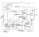
- Fig. 1 is a block diagram view of an input section of a video test and measurement instrument according to the present invention.
- a video signal is received at a video input port 11 of a video test and measurement instrument 10 and routed to both analog and digital video input paths 13 , 15 .
- the analog video input path 13 may include an analog video buffer 12 that receives the video signal and routes it as an analog video signal to a video switch 14 .
- the digital video input path 15 has a conventional digital video receiver that may include an automatic equalizer 16 , a clock recovery and data slicing module 18 , a serial to parallel converter 20 and a composite encoder 22 in series to process the input video signal, the output of which is a digital video signal for input to the video switch 14 .
- the output of the digital receiver may be converted to analog by a digital to analog converter as part of the encoder 22 prior to input to the video switch 14 , or alternatively the output of the analog video buffer 12 may be converted to digital by an analog to digital converter prior to input to the video switch so that both inputs to the video switch are in the same video format.
- Which video input path 13, 15 is converted to the other video format is a function of the processing hardware in the instrument at the output of the video switch 14 .
- a decision module 24 may receive a carrier detect signal from the equalizer 16 , a clock recovery lock signal from the clock recovery module 18 and/or a video standard signal from the converter 20 . From these information signals the decision module 24 automatically determines whether the video signal is analog or serial digital and provides a select signal to the video switch 14 accordingly.
- the output from the video switch 14 is the video signal from the video input path 13, 15 selected by the decision module 24 for further processing by the instrument.
- Also input to the switch 14 is a manual switch override control signal that overrides the output from the decision module 24 if desired by a user.
- the serial digital video receiver 16-22 may be contained within a standard serial digital video receiver chip set that provides the information signals to the decision module 24 indicated above.
- the decision module 24 determines whether a serial digital video signal is present at the video input. If there is, the output from the serial digital video receiver is output by the video switch 14 , otherwise the output from the video switch is from the analog video buffer 12 .
- a phase locked loop (PLL) in the serial digital video receiver chip set reports a video lock, then a variable lock is set to "1", otherwise it is "0".
- the following routine may be used to filter some glitches out of lock . If the variable detSdVideoStd equals the constant SdStd_Unlocked , the analog signal is selected, otherwise the digital signal is selected unless the selection is overridden.
- the switch override or INPUT_CTL signal to the video switch 14 may have three settings - AUTO (input auto detected), DIGITAL (input assumed to always be digital) and ANALOG (input always assumed to be analog).
- the Carrier Detect signal also may be used, either alone or as a qualifier for the Lock signal. In this case the decision may be based as follows: "If Carrier Detect is true, then go to digital"; or "If Carrier Detect is true and Lock is true, then go to digital.”
- the Carrier Detect signal is less discriminating than the Lock signal since it responds to any large signal in the range of 100 to 500 MHz, even if it is just noise.
- a more discriminating decision than one based on the Lock signal only is one where the Video Standard signal is used. If the Video Standard signal is one that is recognized and/or used by the instrument, then it may be used to qualify the Lock signal to make the determination as to whether the video signal at the video input port is digital or analog.
- the present invention provides a video test and measurement instrument having a single video input port to which the inputs of both an analog and a digital video input path are coupled, the output of each video input path being input to a video switch, and having a decision module that receives information from the digital video input path to whether a video signal at the video input port is analog or digital, the video input path that is switched to the output of the video switch being a function of the information (automatic) and a switch override control signal.
Landscapes
- Engineering & Computer Science (AREA)
- Multimedia (AREA)
- Signal Processing (AREA)
- Computer Networks & Wireless Communication (AREA)
- Health & Medical Sciences (AREA)
- Biomedical Technology (AREA)
- General Health & Medical Sciences (AREA)
- Databases & Information Systems (AREA)
- Testing, Inspecting, Measuring Of Stereoscopic Televisions And Televisions (AREA)
- Studio Circuits (AREA)
- Picture Signal Circuits (AREA)
Abstract
Description
- The present invention relates to video test and measurement instruments, and more particularly to a video test and measurement instrument having a single input for receiving either an analog or a serial digital video signal with the ability to automatically switch internal processing accordingly.
- In the current transitional stage from analog to digital video environments, many video studios operate in a mixed environment - having both analog and serial digital video sources available. In order to observe the quality of the video signal from these sources, a user has to know which type of source is being tested/measured in order to use an appropriate instrument. This in the past has required the user to have at least two instruments with him - one for analog video and one for digital video. Alternatively the user has a single instrument with a converter to convert from the type of signal of the source to the type of signal acceptable by the instrument. Currently there are waveform monitors available for both analog and digital video signals. But these instruments have separate analog and digital video input ports. Even with these instruments the user has to know what type of source he is measuring in order to connect it to the proper video input port. For a handheld instrument with limited real estate, having two different video input ports is not practical.
- What is desired is the ability to have a single video input port for an instrument that accepts either analog or serial digital video signals with an automatic video switch between analog and digital video input paths within the instrument.
- Accordingly the present invention provides an instrument having a single video input port for analog or serial digital video signals with an automatic video switch within the instrument between an analog and a serial digital video input path. The outputs of the analog and serial digital video input paths are provided as respective inputs to a video switch, the output of which is then provided to the instrument for further processing. Information from the serial digital video input path, which may include clock recovery lock, carrier detect and/or video standard, is provided to a decision module that generates a select signal for the video switch. As an example, if "lock" is present, then the output from the serial digital video input path is selected for output by the video switch, otherwise the output from the analog video input path is selected. The automatic selection for the switch may be manually overridden. A text display is provided to indicate which video input path the instrument is processing according to the output from the video switch, as well as information about the video signal at the video input port.
- The objects, advantages and other novel features of the present invention are apparent from the following detailed description when read in conjunction with the appended claims and attached drawing.
- Fig. 1 is a block diagram view of an input section of a video test and measurement instrument according to the present invention.
- Referring now to Fig. 1 a video signal, either analog or serial digital format, is received at a video input port 11 of a video test and
measurement instrument 10 and routed to both analog and digitalvideo input paths video input path 13 may include ananalog video buffer 12 that receives the video signal and routes it as an analog video signal to avideo switch 14. The digitalvideo input path 15 has a conventional digital video receiver that may include anautomatic equalizer 16, a clock recovery anddata slicing module 18, a serial toparallel converter 20 and acomposite encoder 22 in series to process the input video signal, the output of which is a digital video signal for input to thevideo switch 14. The output of the digital receiver may be converted to analog by a digital to analog converter as part of theencoder 22 prior to input to thevideo switch 14, or alternatively the output of theanalog video buffer 12 may be converted to digital by an analog to digital converter prior to input to the video switch so that both inputs to the video switch are in the same video format. Whichvideo input path video switch 14. - A
decision module 24 may receive a carrier detect signal from theequalizer 16, a clock recovery lock signal from theclock recovery module 18 and/or a video standard signal from theconverter 20. From these information signals thedecision module 24 automatically determines whether the video signal is analog or serial digital and provides a select signal to thevideo switch 14 accordingly. The output from thevideo switch 14 is the video signal from thevideo input path decision module 24 for further processing by the instrument. Also input to theswitch 14 is a manual switch override control signal that overrides the output from thedecision module 24 if desired by a user. - The serial digital video receiver 16-22 may be contained within a standard serial digital video receiver chip set that provides the information signals to the
decision module 24 indicated above. Thedecision module 24 determines whether a serial digital video signal is present at the video input. If there is, the output from the serial digital video receiver is output by thevideo switch 14, otherwise the output from the video switch is from theanalog video buffer 12. As an example, if a phase locked loop (PLL) in the serial digital video receiver chip set reports a video lock, then a variable lock is set to "1", otherwise it is "0". The following routine may be used to filter some glitches out of lock.If the variable detSdVideoStd equals the constant SdStd_Unlocked, the analog signal is selected, otherwise the digital signal is selected unless the selection is overridden.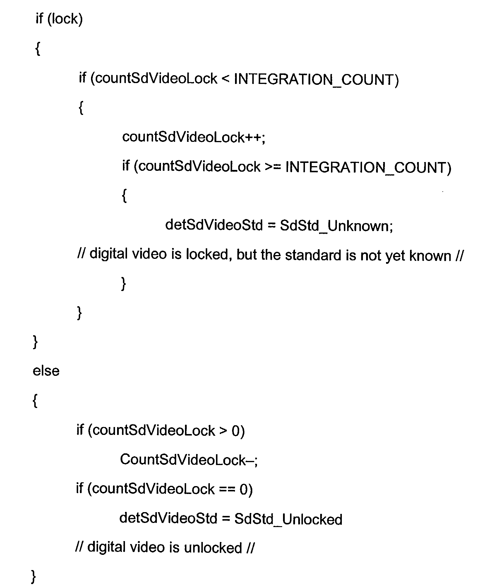
- The switch override or INPUT_CTL signal to the
video switch 14 may have three settings - AUTO (input auto detected), DIGITAL (input assumed to always be digital) and ANALOG (input always assumed to be analog). A text indicator on a screen of the instrument associated with video type depends on the INPUT_CTL setting and other conditions, as set forth in the following table:SETTINGS CONDITIONS TEXT DISPLAYED INPUT_CTL = AUTO Digital video lock DIGITAL No digital video lock ANALOG Digital video lock to unsupported standard Name of video standard INPUT_CTL = DIGITAL Digital video lock DIGITAL No digital video lock UNLOCKED Digital video lock to unsupported standard Name of video standard INPUT_CTL = ANALOG Any No display - Although the above description used only the Lock signal in the
decision module 24, the Carrier Detect signal also may be used, either alone or as a qualifier for the Lock signal. In this case the decision may be based as follows: "If Carrier Detect is true, then go to digital"; or "If Carrier Detect is true and Lock is true, then go to digital." The Carrier Detect signal is less discriminating than the Lock signal since it responds to any large signal in the range of 100 to 500 MHz, even if it is just noise. A more discriminating decision than one based on the Lock signal only is one where the Video Standard signal is used. If the Video Standard signal is one that is recognized and/or used by the instrument, then it may be used to qualify the Lock signal to make the determination as to whether the video signal at the video input port is digital or analog. - Thus the present invention provides a video test and measurement instrument having a single video input port to which the inputs of both an analog and a digital video input path are coupled, the output of each video input path being input to a video switch, and having a decision module that receives information from the digital video input path to whether a video signal at the video input port is analog or digital, the video input path that is switched to the output of the video switch being a function of the information (automatic) and a switch override control signal.
Claims (11)
- A video test and measurement instrument comprising:means for coupling a common video input port to an input of an analog video input path and an input of a digital video input path, each video input path having a separate output;means for automatically switching between the separate outputs in response to information derived from the digital video input to provide an output video signal corresponding to the video format of a video signal applied to the common video input port.
- The instrument as recited in claim 1 wherein the automatically switching means comprises:a video switch having respective inputs coupled one to each of the separate outputs, having a select input and having an output to provide the output video signal; anda decision module for generating a select signal as a function of the information, the select signal being applied to the select input in order to switch the output between the separate outputs according to the video format of the video signal.
- A method of automatically switching between analog and digital video input paths in a video test and measurement instrument comprising the steps of:coupling an input of the analog video input path to a video input port;coupling an input of the digital video input path to the video input port;coupling inputs of a video switch to respective outputs of the analog and digital video input paths; andgenerating a select signal for the video switch as a function of information derived from the digital video input path to select which video input path is coupled to an output of the video switch for further processing by the video test and measurement instrument.
- The method as recited in claim 3 further comprising the step of providing a text message on a display of the video test and measurement instrument indicative of which video input path is selected for output by the video switch.
- The method as recited in claim 4 wherein the test message includes information about a video signal coupled to the video input port.
- An apparatus for processing a video signal applied to an input port of a test and measurement instrument comprising:an analog buffer having an input coupled to the input port and having an output to form an analog video input path;a digital video receiver having an input coupled to the input port and having an output to form a digital video input path;a video switch having inputs coupled to the respective outputs of the analog and digital video input paths; anda decision module having as inputs information from the digital video receiver and having an output coupled to a select input of the video switch, the decision module generating a select signal at its output as a function of the information to select which video input path output is provided at the output of the video switch.
- The apparatus as recited in claim 6 wherein the information includes one or more of a lock signal, a carrier detect signal and a video standard signal.
- The apparatus as recited in claim 7 wherein the decision module generates the select signal as a function of the lock signal.
- The apparatus as recited in claim 7 wherein the decision module generates the select signal as a function of the carrier detect signal.
- The apparatus as recited in claim 7 wherein the decision module generates the select signal as a function of the lock and carrier detect signals.
- The apparatus as recited in claim 7 wherein the decision module generates the select signal as a function of the video standard and lock signals.
Applications Claiming Priority (2)
| Application Number | Priority Date | Filing Date | Title |
|---|---|---|---|
| US124015 | 1980-02-25 | ||
| US10/124,015 US6924834B2 (en) | 2002-04-16 | 2002-04-16 | Analog or serial digital video input with automatic video switch |
Publications (2)
| Publication Number | Publication Date |
|---|---|
| EP1355502A1 true EP1355502A1 (en) | 2003-10-22 |
| EP1355502B1 EP1355502B1 (en) | 2008-11-05 |
Family
ID=28674680
Family Applications (1)
| Application Number | Title | Priority Date | Filing Date |
|---|---|---|---|
| EP03252224A Expired - Lifetime EP1355502B1 (en) | 2002-04-16 | 2003-04-08 | Video measurement instrument having a common input port for analog and digital video signals |
Country Status (5)
| Country | Link |
|---|---|
| US (1) | US6924834B2 (en) |
| EP (1) | EP1355502B1 (en) |
| JP (1) | JP2004007573A (en) |
| CN (1) | CN100508626C (en) |
| DE (1) | DE60324494D1 (en) |
Cited By (1)
| Publication number | Priority date | Publication date | Assignee | Title |
|---|---|---|---|---|
| EP2993897A1 (en) * | 2014-09-05 | 2016-03-09 | Icatch Inc | Digital video recorder and video recording and playback method thereof |
Families Citing this family (8)
| Publication number | Priority date | Publication date | Assignee | Title |
|---|---|---|---|---|
| US7728911B2 (en) * | 2005-01-26 | 2010-06-01 | Hewlett-Packard Development Company, L.P. | Positively indicating to user whether signal has been detected on each video input |
| CN1862651B (en) * | 2005-05-13 | 2010-05-26 | 鸿富锦精密工业(深圳)有限公司 | Signal conversion device and interface automatic switching method |
| US8004887B2 (en) * | 2008-11-07 | 2011-08-23 | Micron Technology, Inc. | Configurable digital and analog input/output interface in a memory device |
| US10171409B2 (en) * | 2012-12-04 | 2019-01-01 | Selligent, Inc. | Systems and methods for path optimization in a message campaign |
| US20160048366A1 (en) * | 2014-08-14 | 2016-02-18 | David John Cowin | Video Streaming System and Method for a Wearable Display |
| CN105391963A (en) * | 2014-09-05 | 2016-03-09 | 可取国际股份有限公司 | Digital video recorder and video recording method |
| CN106375761A (en) * | 2016-08-31 | 2017-02-01 | 北京利亚德视频技术有限公司 | Signal self-adaptive decoding method and device |
| CN108259786A (en) * | 2018-02-01 | 2018-07-06 | 龚剑 | A kind of signal processing method and equipment |
Citations (9)
| Publication number | Priority date | Publication date | Assignee | Title |
|---|---|---|---|---|
| JPH11261906A (en) * | 1998-01-12 | 1999-09-24 | Sony Corp | TV broadcast receiving apparatus, TV broadcast receiving method, and TV broadcast method |
| GB2338854A (en) * | 1998-06-26 | 1999-12-29 | Samsung Electronics Co Ltd | Combined digital/analog broadcast TV signal processing unit |
| WO2000062535A1 (en) * | 1999-04-09 | 2000-10-19 | Sony Electronics, Inc. | Method for switching input terminal based on incoming signal format |
| WO2001006775A1 (en) * | 1999-07-16 | 2001-01-25 | Thomson Licensing S.A. | Method and apparatus for autoprogramming a television receiver |
| EP1134989A1 (en) * | 1999-10-04 | 2001-09-19 | Promax Electronica, S.A. | Digital and/or analogic television carrier signals and device for measuring and processing digital and/or analogic television carrier signals |
| US20010033625A1 (en) * | 2000-03-30 | 2001-10-25 | Kunio Ninomiya | Multi-system correspondence receiver |
| US6369857B1 (en) * | 1999-05-13 | 2002-04-09 | Sarnoff Corporation | Receiver for analog and digital television signals |
| EP1280275A1 (en) * | 2001-07-19 | 2003-01-29 | Pioneer Corporation | Automatic tuning apparatus |
| US20030035065A1 (en) * | 2001-08-17 | 2003-02-20 | Hak-Jae Kim | Device and method for automatically discriminating between formats of video signals |
Family Cites Families (3)
| Publication number | Priority date | Publication date | Assignee | Title |
|---|---|---|---|---|
| US4554636A (en) * | 1982-09-30 | 1985-11-19 | Allied Corporation | Apparatus for testing circuits within a system |
| EP0423979B1 (en) * | 1989-10-20 | 1997-07-09 | Sony Corporation | High definition video signal recording systems |
| US5614944A (en) * | 1994-03-30 | 1997-03-25 | Nec Corporation | Test method and apparatus of sequentially executing synchronous signal test, dot level test, and gradation test of a video signal generator |
-
2002
- 2002-04-16 US US10/124,015 patent/US6924834B2/en not_active Expired - Lifetime
-
2003
- 2003-04-08 EP EP03252224A patent/EP1355502B1/en not_active Expired - Lifetime
- 2003-04-08 DE DE60324494T patent/DE60324494D1/en not_active Expired - Lifetime
- 2003-04-11 JP JP2003108303A patent/JP2004007573A/en active Pending
- 2003-04-15 CN CN03110444.4A patent/CN100508626C/en not_active Expired - Fee Related
Patent Citations (10)
| Publication number | Priority date | Publication date | Assignee | Title |
|---|---|---|---|---|
| JPH11261906A (en) * | 1998-01-12 | 1999-09-24 | Sony Corp | TV broadcast receiving apparatus, TV broadcast receiving method, and TV broadcast method |
| US6490001B1 (en) * | 1998-01-12 | 2002-12-03 | Sony Corporation | Apparatus and method increasing speed of receiving television broadcasts |
| GB2338854A (en) * | 1998-06-26 | 1999-12-29 | Samsung Electronics Co Ltd | Combined digital/analog broadcast TV signal processing unit |
| WO2000062535A1 (en) * | 1999-04-09 | 2000-10-19 | Sony Electronics, Inc. | Method for switching input terminal based on incoming signal format |
| US6369857B1 (en) * | 1999-05-13 | 2002-04-09 | Sarnoff Corporation | Receiver for analog and digital television signals |
| WO2001006775A1 (en) * | 1999-07-16 | 2001-01-25 | Thomson Licensing S.A. | Method and apparatus for autoprogramming a television receiver |
| EP1134989A1 (en) * | 1999-10-04 | 2001-09-19 | Promax Electronica, S.A. | Digital and/or analogic television carrier signals and device for measuring and processing digital and/or analogic television carrier signals |
| US20010033625A1 (en) * | 2000-03-30 | 2001-10-25 | Kunio Ninomiya | Multi-system correspondence receiver |
| EP1280275A1 (en) * | 2001-07-19 | 2003-01-29 | Pioneer Corporation | Automatic tuning apparatus |
| US20030035065A1 (en) * | 2001-08-17 | 2003-02-20 | Hak-Jae Kim | Device and method for automatically discriminating between formats of video signals |
Cited By (1)
| Publication number | Priority date | Publication date | Assignee | Title |
|---|---|---|---|---|
| EP2993897A1 (en) * | 2014-09-05 | 2016-03-09 | Icatch Inc | Digital video recorder and video recording and playback method thereof |
Also Published As
| Publication number | Publication date |
|---|---|
| US6924834B2 (en) | 2005-08-02 |
| CN100508626C (en) | 2009-07-01 |
| US20030197783A1 (en) | 2003-10-23 |
| JP2004007573A (en) | 2004-01-08 |
| EP1355502B1 (en) | 2008-11-05 |
| DE60324494D1 (en) | 2008-12-18 |
| CN1452412A (en) | 2003-10-29 |
Similar Documents
| Publication | Publication Date | Title |
|---|---|---|
| US6924834B2 (en) | Analog or serial digital video input with automatic video switch | |
| US4901147A (en) | Video system with self-diagnose function | |
| US7342393B2 (en) | Multimeter with filtered measurement mode | |
| US7009660B2 (en) | Device and method for automatically discriminating between formats of video signals | |
| US5278565A (en) | Apparatus for setting individual different electronic devices of an equipment system | |
| US20110176810A1 (en) | System and method for multi-rate, high-sensitivity clock and data recovery with adjustable decision threshold, rf input, and optical-to-electrical conversion | |
| US7031685B2 (en) | Receiver for regenerating a signal wave via digital signal processing | |
| JPH02280066A (en) | Method for discriminating actual response from spurious response by frequency sweep spectrum analyzer | |
| EP0776086B1 (en) | Signal generator | |
| US7263145B2 (en) | Semiconductor integrated circuit device, wireless LAN system, and auto gain control system | |
| US6798444B2 (en) | Television-set adjusting system | |
| US6370484B1 (en) | Signal analyzer having independent analysis and display scales | |
| US9716527B2 (en) | Method and device for the analysis of code domain power and code domain error power | |
| CN1984273A (en) | Video apparatus and video processing method | |
| CN214473606U (en) | Double-channel spectrum analyzer | |
| US6483550B1 (en) | Video signal level converting device and video signal analog-to-digital converter | |
| US20080094184A1 (en) | Electronic system having a plurality of individually operable user stations | |
| CN114189290B (en) | Signal generation system and signal generation method | |
| KR20020078925A (en) | Bts test unit capable of analyzing spectrum | |
| CN101076091A (en) | Portable digital TV-set monitor for automatically recognizing digital and analog TV-set signal | |
| JP2586953B2 (en) | Meter characteristic selection device | |
| JPH07209353A (en) | Spectrum analyzer | |
| CN120281404A (en) | Radio comprehensive test module | |
| JPH08195893A (en) | Sync separation circuit | |
| EP0614320A2 (en) | Television receiver and television signal determination circuit |
Legal Events
| Date | Code | Title | Description |
|---|---|---|---|
| PUAI | Public reference made under article 153(3) epc to a published international application that has entered the european phase |
Free format text: ORIGINAL CODE: 0009012 |
|
| AK | Designated contracting states |
Kind code of ref document: A1 Designated state(s): AT BE BG CH CY CZ DE DK EE ES FI FR GB GR HU IE IT LI LU MC NL PT RO SE SI SK TR |
|
| AX | Request for extension of the european patent |
Extension state: AL LT LV MK |
|
| 17P | Request for examination filed |
Effective date: 20040419 |
|
| AKX | Designation fees paid |
Designated state(s): DE GB |
|
| RTI1 | Title (correction) |
Free format text: VIDEO MEASUREMENT INSTRUMENT HAVING A COMMON INPUT PORT FOR ANALOG AND DIGITAL VIDEO SIGNALS |
|
| GRAP | Despatch of communication of intention to grant a patent |
Free format text: ORIGINAL CODE: EPIDOSNIGR1 |
|
| GRAS | Grant fee paid |
Free format text: ORIGINAL CODE: EPIDOSNIGR3 |
|
| GRAA | (expected) grant |
Free format text: ORIGINAL CODE: 0009210 |
|
| AK | Designated contracting states |
Kind code of ref document: B1 Designated state(s): DE GB |
|
| REG | Reference to a national code |
Ref country code: GB Ref legal event code: FG4D |
|
| REF | Corresponds to: |
Ref document number: 60324494 Country of ref document: DE Date of ref document: 20081218 Kind code of ref document: P |
|
| PLBE | No opposition filed within time limit |
Free format text: ORIGINAL CODE: 0009261 |
|
| STAA | Information on the status of an ep patent application or granted ep patent |
Free format text: STATUS: NO OPPOSITION FILED WITHIN TIME LIMIT |
|
| 26N | No opposition filed |
Effective date: 20090806 |
|
| PGFP | Annual fee paid to national office [announced via postgrant information from national office to epo] |
Ref country code: DE Payment date: 20180427 Year of fee payment: 16 |
|
| PGFP | Annual fee paid to national office [announced via postgrant information from national office to epo] |
Ref country code: GB Payment date: 20180427 Year of fee payment: 16 |
|
| REG | Reference to a national code |
Ref country code: DE Ref legal event code: R119 Ref document number: 60324494 Country of ref document: DE |
|
| GBPC | Gb: european patent ceased through non-payment of renewal fee |
Effective date: 20190408 |
|
| PG25 | Lapsed in a contracting state [announced via postgrant information from national office to epo] |
Ref country code: GB Free format text: LAPSE BECAUSE OF NON-PAYMENT OF DUE FEES Effective date: 20190408 Ref country code: DE Free format text: LAPSE BECAUSE OF NON-PAYMENT OF DUE FEES Effective date: 20191101 |
|
| REG | Reference to a national code |
Ref country code: DE Ref legal event code: R082 Ref document number: 60324494 Country of ref document: DE Representative=s name: HGF EUROPE LLP, DE Ref country code: DE Ref legal event code: R081 Ref document number: 60324494 Country of ref document: DE Owner name: PROJECT GIANTS, LLC (N.D.GES.D.STAATES DELAWAR, US Free format text: FORMER OWNER: TEKTRONIX, INC., BEAVERTON, OREG., US |
|
| REG | Reference to a national code |
Ref country code: GB Ref legal event code: 732E Free format text: REGISTERED BETWEEN 20210527 AND 20210602 |