EP1355461B1 - Method and unit for bit stream decoding - Google Patents
Method and unit for bit stream decoding Download PDFInfo
- Publication number
- EP1355461B1 EP1355461B1 EP03008741A EP03008741A EP1355461B1 EP 1355461 B1 EP1355461 B1 EP 1355461B1 EP 03008741 A EP03008741 A EP 03008741A EP 03008741 A EP03008741 A EP 03008741A EP 1355461 B1 EP1355461 B1 EP 1355461B1
- Authority
- EP
- European Patent Office
- Prior art keywords
- bit
- frame
- communication
- shall
- node
- Prior art date
- Legal status (The legal status is an assumption and is not a legal conclusion. Google has not performed a legal analysis and makes no representation as to the accuracy of the status listed.)
- Expired - Lifetime
Links
- 238000000034 method Methods 0.000 title claims abstract description 162
- 238000001514 detection method Methods 0.000 claims abstract description 77
- 238000004891 communication Methods 0.000 claims description 774
- 238000001914 filtration Methods 0.000 claims description 100
- 238000005070 sampling Methods 0.000 claims description 30
- 238000004590 computer program Methods 0.000 claims description 8
- 108091006146 Channels Proteins 0.000 description 541
- 238000012937 correction Methods 0.000 description 279
- 230000003068 static effect Effects 0.000 description 237
- 239000000872 buffer Substances 0.000 description 231
- 230000005540 biological transmission Effects 0.000 description 217
- 230000007704 transition Effects 0.000 description 173
- 230000001960 triggered effect Effects 0.000 description 111
- 230000007246 mechanism Effects 0.000 description 102
- 239000013598 vector Substances 0.000 description 81
- 238000012544 monitoring process Methods 0.000 description 74
- 238000010586 diagram Methods 0.000 description 59
- 230000008569 process Effects 0.000 description 57
- 230000008859 change Effects 0.000 description 53
- 230000003993 interaction Effects 0.000 description 53
- 238000004422 calculation algorithm Methods 0.000 description 52
- 230000006870 function Effects 0.000 description 50
- 238000007726 management method Methods 0.000 description 49
- 230000000694 effects Effects 0.000 description 48
- 230000003287 optical effect Effects 0.000 description 48
- 238000005259 measurement Methods 0.000 description 47
- 230000001360 synchronised effect Effects 0.000 description 47
- 230000010354 integration Effects 0.000 description 45
- 230000006399 behavior Effects 0.000 description 42
- 238000004364 calculation method Methods 0.000 description 42
- 230000009471 action Effects 0.000 description 41
- 238000012360 testing method Methods 0.000 description 39
- 238000012545 processing Methods 0.000 description 35
- 238000003708 edge detection Methods 0.000 description 34
- 230000011664 signaling Effects 0.000 description 29
- 238000010200 validation analysis Methods 0.000 description 27
- 230000015654 memory Effects 0.000 description 25
- 238000003745 diagnosis Methods 0.000 description 19
- 230000003247 decreasing effect Effects 0.000 description 16
- 230000000630 rising effect Effects 0.000 description 16
- 238000012546 transfer Methods 0.000 description 16
- 125000004122 cyclic group Chemical group 0.000 description 15
- 239000003999 initiator Substances 0.000 description 15
- 230000006833 reintegration Effects 0.000 description 15
- 230000009977 dual effect Effects 0.000 description 14
- 230000000737 periodic effect Effects 0.000 description 13
- 230000004044 response Effects 0.000 description 10
- 206010000210 abortion Diseases 0.000 description 9
- 230000002829 reductive effect Effects 0.000 description 8
- 230000002618 waking effect Effects 0.000 description 8
- 230000000977 initiatory effect Effects 0.000 description 7
- 230000000873 masking effect Effects 0.000 description 7
- 238000012986 modification Methods 0.000 description 6
- 230000004048 modification Effects 0.000 description 6
- 238000003860 storage Methods 0.000 description 6
- 230000004913 activation Effects 0.000 description 5
- 238000013016 damping Methods 0.000 description 5
- 230000001934 delay Effects 0.000 description 5
- 238000013461 design Methods 0.000 description 4
- 238000000605 extraction Methods 0.000 description 4
- 238000011084 recovery Methods 0.000 description 4
- 230000000717 retained effect Effects 0.000 description 4
- 239000004065 semiconductor Substances 0.000 description 4
- 230000002123 temporal effect Effects 0.000 description 4
- 108010076504 Protein Sorting Signals Proteins 0.000 description 3
- 238000009825 accumulation Methods 0.000 description 3
- 239000000470 constituent Substances 0.000 description 3
- 239000013078 crystal Substances 0.000 description 3
- 238000009826 distribution Methods 0.000 description 3
- 239000000203 mixture Substances 0.000 description 3
- 230000001151 other effect Effects 0.000 description 3
- 230000036961 partial effect Effects 0.000 description 3
- 230000000644 propagated effect Effects 0.000 description 3
- 230000007727 signaling mechanism Effects 0.000 description 3
- 241000283986 Lepus Species 0.000 description 2
- XUIMIQQOPSSXEZ-UHFFFAOYSA-N Silicon Chemical compound [Si] XUIMIQQOPSSXEZ-UHFFFAOYSA-N 0.000 description 2
- 238000013459 approach Methods 0.000 description 2
- 230000008901 benefit Effects 0.000 description 2
- 230000015572 biosynthetic process Effects 0.000 description 2
- 238000012508 change request Methods 0.000 description 2
- 238000006243 chemical reaction Methods 0.000 description 2
- 239000003795 chemical substances by application Substances 0.000 description 2
- 238000013500 data storage Methods 0.000 description 2
- 230000007547 defect Effects 0.000 description 2
- 230000002950 deficient Effects 0.000 description 2
- 238000012217 deletion Methods 0.000 description 2
- 230000037430 deletion Effects 0.000 description 2
- 230000001419 dependent effect Effects 0.000 description 2
- 238000011156 evaluation Methods 0.000 description 2
- 239000000284 extract Substances 0.000 description 2
- 238000013507 mapping Methods 0.000 description 2
- 238000000691 measurement method Methods 0.000 description 2
- 238000005457 optimization Methods 0.000 description 2
- 230000003252 repetitive effect Effects 0.000 description 2
- 230000035945 sensitivity Effects 0.000 description 2
- 229910052710 silicon Inorganic materials 0.000 description 2
- 239000010703 silicon Substances 0.000 description 2
- 208000027765 speech disease Diseases 0.000 description 2
- 238000012795 verification Methods 0.000 description 2
- CVOFKRWYWCSDMA-UHFFFAOYSA-N 2-chloro-n-(2,6-diethylphenyl)-n-(methoxymethyl)acetamide;2,6-dinitro-n,n-dipropyl-4-(trifluoromethyl)aniline Chemical compound CCC1=CC=CC(CC)=C1N(COC)C(=O)CCl.CCCN(CCC)C1=C([N+]([O-])=O)C=C(C(F)(F)F)C=C1[N+]([O-])=O CVOFKRWYWCSDMA-UHFFFAOYSA-N 0.000 description 1
- RYGMFSIKBFXOCR-UHFFFAOYSA-N Copper Chemical compound [Cu] RYGMFSIKBFXOCR-UHFFFAOYSA-N 0.000 description 1
- 101710201354 Metallothionein A Proteins 0.000 description 1
- 101710094503 Metallothionein-1 Proteins 0.000 description 1
- 230000003542 behavioural effect Effects 0.000 description 1
- 230000015556 catabolic process Effects 0.000 description 1
- 239000000919 ceramic Substances 0.000 description 1
- 239000003086 colorant Substances 0.000 description 1
- 239000012141 concentrate Substances 0.000 description 1
- 238000010276 construction Methods 0.000 description 1
- 230000007423 decrease Effects 0.000 description 1
- 238000006731 degradation reaction Methods 0.000 description 1
- 230000003111 delayed effect Effects 0.000 description 1
- 230000006866 deterioration Effects 0.000 description 1
- 238000011161 development Methods 0.000 description 1
- 238000005516 engineering process Methods 0.000 description 1
- 238000007667 floating Methods 0.000 description 1
- 239000012634 fragment Substances 0.000 description 1
- 238000009432 framing Methods 0.000 description 1
- 230000036039 immunity Effects 0.000 description 1
- 230000002401 inhibitory effect Effects 0.000 description 1
- 238000003780 insertion Methods 0.000 description 1
- 230000037431 insertion Effects 0.000 description 1
- 230000001788 irregular Effects 0.000 description 1
- 238000005304 joining Methods 0.000 description 1
- 230000000670 limiting effect Effects 0.000 description 1
- 238000004519 manufacturing process Methods 0.000 description 1
- 239000011159 matrix material Substances 0.000 description 1
- 239000002674 ointment Substances 0.000 description 1
- 230000008520 organization Effects 0.000 description 1
- 230000008447 perception Effects 0.000 description 1
- 230000002028 premature Effects 0.000 description 1
- 238000012913 prioritisation Methods 0.000 description 1
- 238000012797 qualification Methods 0.000 description 1
- 238000001303 quality assessment method Methods 0.000 description 1
- 230000002441 reversible effect Effects 0.000 description 1
- 238000012552 review Methods 0.000 description 1
- 238000000638 solvent extraction Methods 0.000 description 1
- 238000004677 spark ionization mass spectrometry Methods 0.000 description 1
- 230000002269 spontaneous effect Effects 0.000 description 1
- 239000007858 starting material Substances 0.000 description 1
- 230000001052 transient effect Effects 0.000 description 1
- 238000009827 uniform distribution Methods 0.000 description 1
- 230000003245 working effect Effects 0.000 description 1
Images





























Classifications
-
- H—ELECTRICITY
- H04—ELECTRIC COMMUNICATION TECHNIQUE
- H04L—TRANSMISSION OF DIGITAL INFORMATION, e.g. TELEGRAPHIC COMMUNICATION
- H04L12/00—Data switching networks
- H04L12/28—Data switching networks characterised by path configuration, e.g. LAN [Local Area Networks] or WAN [Wide Area Networks]
- H04L12/40—Bus networks
- H04L12/40006—Architecture of a communication node
- H04L12/40026—Details regarding a bus guardian
-
- H—ELECTRICITY
- H03—ELECTRONIC CIRCUITRY
- H03M—CODING; DECODING; CODE CONVERSION IN GENERAL
- H03M13/00—Coding, decoding or code conversion, for error detection or error correction; Coding theory basic assumptions; Coding bounds; Error probability evaluation methods; Channel models; Simulation or testing of codes
- H03M13/37—Decoding methods or techniques, not specific to the particular type of coding provided for in groups H03M13/03 - H03M13/35
- H03M13/43—Majority logic or threshold decoding
-
- H—ELECTRICITY
- H04—ELECTRIC COMMUNICATION TECHNIQUE
- H04J—MULTIPLEX COMMUNICATION
- H04J3/00—Time-division multiplex systems
- H04J3/02—Details
- H04J3/06—Synchronising arrangements
- H04J3/0635—Clock or time synchronisation in a network
- H04J3/0638—Clock or time synchronisation among nodes; Internode synchronisation
- H04J3/0652—Synchronisation among time division multiple access [TDMA] nodes, e.g. time triggered protocol [TTP]
-
- H—ELECTRICITY
- H04—ELECTRIC COMMUNICATION TECHNIQUE
- H04L—TRANSMISSION OF DIGITAL INFORMATION, e.g. TELEGRAPHIC COMMUNICATION
- H04L12/00—Data switching networks
- H04L12/28—Data switching networks characterised by path configuration, e.g. LAN [Local Area Networks] or WAN [Wide Area Networks]
- H04L12/40—Bus networks
- H04L12/403—Bus networks with centralised control, e.g. polling
- H04L12/4035—Bus networks with centralised control, e.g. polling in which slots of a TDMA packet structure are assigned based on a contention resolution carried out at a master unit
-
- H—ELECTRICITY
- H04—ELECTRIC COMMUNICATION TECHNIQUE
- H04L—TRANSMISSION OF DIGITAL INFORMATION, e.g. TELEGRAPHIC COMMUNICATION
- H04L12/00—Data switching networks
- H04L12/28—Data switching networks characterised by path configuration, e.g. LAN [Local Area Networks] or WAN [Wide Area Networks]
- H04L12/40—Bus networks
- H04L12/407—Bus networks with decentralised control
- H04L12/417—Bus networks with decentralised control with deterministic access, e.g. token passing
-
- H—ELECTRICITY
- H04—ELECTRIC COMMUNICATION TECHNIQUE
- H04L—TRANSMISSION OF DIGITAL INFORMATION, e.g. TELEGRAPHIC COMMUNICATION
- H04L12/00—Data switching networks
- H04L12/28—Data switching networks characterised by path configuration, e.g. LAN [Local Area Networks] or WAN [Wide Area Networks]
- H04L12/44—Star or tree networks
-
- H—ELECTRICITY
- H04—ELECTRIC COMMUNICATION TECHNIQUE
- H04L—TRANSMISSION OF DIGITAL INFORMATION, e.g. TELEGRAPHIC COMMUNICATION
- H04L12/00—Data switching networks
- H04L12/64—Hybrid switching systems
- H04L12/6418—Hybrid transport
-
- H—ELECTRICITY
- H04—ELECTRIC COMMUNICATION TECHNIQUE
- H04L—TRANSMISSION OF DIGITAL INFORMATION, e.g. TELEGRAPHIC COMMUNICATION
- H04L43/00—Arrangements for monitoring or testing data switching networks
-
- H—ELECTRICITY
- H04—ELECTRIC COMMUNICATION TECHNIQUE
- H04L—TRANSMISSION OF DIGITAL INFORMATION, e.g. TELEGRAPHIC COMMUNICATION
- H04L7/00—Arrangements for synchronising receiver with transmitter
- H04L7/02—Speed or phase control by the received code signals, the signals containing no special synchronisation information
- H04L7/033—Speed or phase control by the received code signals, the signals containing no special synchronisation information using the transitions of the received signal to control the phase of the synchronising-signal-generating means, e.g. using a phase-locked loop
- H04L7/0331—Speed or phase control by the received code signals, the signals containing no special synchronisation information using the transitions of the received signal to control the phase of the synchronising-signal-generating means, e.g. using a phase-locked loop with a digital phase-locked loop [PLL] processing binary samples, e.g. add/subtract logic for correction of receiver clock
-
- H—ELECTRICITY
- H03—ELECTRONIC CIRCUITRY
- H03M—CODING; DECODING; CODE CONVERSION IN GENERAL
- H03M13/00—Coding, decoding or code conversion, for error detection or error correction; Coding theory basic assumptions; Coding bounds; Error probability evaluation methods; Channel models; Simulation or testing of codes
- H03M13/03—Error detection or forward error correction by redundancy in data representation, i.e. code words containing more digits than the source words
- H03M13/05—Error detection or forward error correction by redundancy in data representation, i.e. code words containing more digits than the source words using block codes, i.e. a predetermined number of check bits joined to a predetermined number of information bits
- H03M13/09—Error detection only, e.g. using cyclic redundancy check [CRC] codes or single parity bit
-
- H—ELECTRICITY
- H04—ELECTRIC COMMUNICATION TECHNIQUE
- H04J—MULTIPLEX COMMUNICATION
- H04J3/00—Time-division multiplex systems
- H04J3/02—Details
- H04J3/06—Synchronising arrangements
- H04J3/0635—Clock or time synchronisation in a network
- H04J3/0682—Clock or time synchronisation in a network by delay compensation, e.g. by compensation of propagation delay or variations thereof, by ranging
-
- H—ELECTRICITY
- H04—ELECTRIC COMMUNICATION TECHNIQUE
- H04J—MULTIPLEX COMMUNICATION
- H04J3/00—Time-division multiplex systems
- H04J3/02—Details
- H04J3/06—Synchronising arrangements
- H04J3/0635—Clock or time synchronisation in a network
- H04J3/0685—Clock or time synchronisation in a node; Intranode synchronisation
- H04J3/0694—Synchronisation in a TDMA node, e.g. TTP
-
- H—ELECTRICITY
- H04—ELECTRIC COMMUNICATION TECHNIQUE
- H04L—TRANSMISSION OF DIGITAL INFORMATION, e.g. TELEGRAPHIC COMMUNICATION
- H04L12/00—Data switching networks
- H04L12/28—Data switching networks characterised by path configuration, e.g. LAN [Local Area Networks] or WAN [Wide Area Networks]
- H04L12/40—Bus networks
- H04L2012/40208—Bus networks characterized by the use of a particular bus standard
- H04L2012/40241—Flexray
-
- H—ELECTRICITY
- H04—ELECTRIC COMMUNICATION TECHNIQUE
- H04L—TRANSMISSION OF DIGITAL INFORMATION, e.g. TELEGRAPHIC COMMUNICATION
- H04L12/00—Data switching networks
- H04L12/28—Data switching networks characterised by path configuration, e.g. LAN [Local Area Networks] or WAN [Wide Area Networks]
- H04L12/40—Bus networks
- H04L2012/40267—Bus for use in transportation systems
- H04L2012/40273—Bus for use in transportation systems the transportation system being a vehicle
-
- H—ELECTRICITY
- H04—ELECTRIC COMMUNICATION TECHNIQUE
- H04L—TRANSMISSION OF DIGITAL INFORMATION, e.g. TELEGRAPHIC COMMUNICATION
- H04L12/00—Data switching networks
- H04L12/64—Hybrid switching systems
- H04L12/6418—Hybrid transport
- H04L2012/6432—Topology
- H04L2012/6435—Bus
-
- H—ELECTRICITY
- H04—ELECTRIC COMMUNICATION TECHNIQUE
- H04L—TRANSMISSION OF DIGITAL INFORMATION, e.g. TELEGRAPHIC COMMUNICATION
- H04L12/00—Data switching networks
- H04L12/64—Hybrid switching systems
- H04L12/6418—Hybrid transport
- H04L2012/6432—Topology
- H04L2012/644—Star
-
- H—ELECTRICITY
- H04—ELECTRIC COMMUNICATION TECHNIQUE
- H04L—TRANSMISSION OF DIGITAL INFORMATION, e.g. TELEGRAPHIC COMMUNICATION
- H04L12/00—Data switching networks
- H04L12/64—Hybrid switching systems
- H04L12/6418—Hybrid transport
- H04L2012/6445—Admission control
- H04L2012/6459—Multiplexing, e.g. TDMA, CDMA
-
- H—ELECTRICITY
- H04—ELECTRIC COMMUNICATION TECHNIQUE
- H04L—TRANSMISSION OF DIGITAL INFORMATION, e.g. TELEGRAPHIC COMMUNICATION
- H04L43/00—Arrangements for monitoring or testing data switching networks
- H04L43/08—Monitoring or testing based on specific metrics, e.g. QoS, energy consumption or environmental parameters
- H04L43/0823—Errors, e.g. transmission errors
- H04L43/0847—Transmission error
Definitions
- the invention refers to a computer program, which is able to run on a computer, in particular on a microprocessor.
- the invention refers to a unit for decoding a bit stream.
- the bit stream comprises a number of consecutive samples.
- the bit stream decoding unit comprises means for positioning a predefined detection window at certain positions on the bit stream, the detection window being predefined in order to comprise a number of samples, the detection window being positioned in such a way as to comprise certain samples with respective sample values; means for applying a majority voting to the sample values comprised by the detection window in order to detect the occurrence of an edge in the bit stream; and means for decoding the bit stream according to the result of the majority voting and for generating respective bit values.
- the present invention refers to a node for a communication system.
- the communication system comprises a communication media, said node and at least one further node.
- the nodes are connected to the communication media for transmitting data among the nodes.
- the data is transmitted across the communication media in the form of a bit stream, the bit stream comprising a number of consecutive samples.
- EP 0 412 234 A2 discloses a device for bit stream decoding in which an input signal is demodulated and digital data corresponding to a demodulated base band signal is recovered. An oscillator with a fixed frequency is used for generating a clock signal for sampling and decoding the bit stream.
- Deviations of the frequency of the clock signal in respect to the frequency used for sampling and decoding the bit stream are compensated by means of a clock recovery circuit, which adds or removes pulses from the clock signal for generating corrected clock signals used for sampling and decoding.
- Bit edge detection and synchronization of the clock signal is performed at every zero-cross point on the base band signal, that is on every edge of the signal.
- the rising edge of the clock signal is synchronized on the rising edge of the zero-cross point on the base band signal.
- GB 1 560 270 discloses a device for bit stream decoding in which an input signal is demodulated and digital data corresponding to a demodulated input signal is recovered.
- An oscillator with a fixed frequency is used for generating a clock signal for sampling and decoding the bit stream.
- the clock signal is synchronized on each transition of the input signal, that is on every edge of the signal.
- the input signal comprises a serial NRZ bit stream, it is disclosed to insert a synchronizing preamble into the transmitted data stream, whenever a consecutive stream of bits at the same logic level exceeds a specified time. Deviations of the frequency of the clock signal in respect to the frequency used for sampling and decoding the bit stream are compensated by means of a clock recovery circuit. Bit edge detection and synchronization of the clock signal is performed at every transition of the incoming data stream. The rising edge of the clock signal is synchronized on the transition of the input signal.
- Various types of communication systems are known in the art. Generally, they comprise a communication media, which for example is a data bus. Various nodes are connected to the communication media. Each node comprises a host controller, a communication controller, a bus driver and optionally a bus guardian. Data can be transmitted across the communication system according to various protocols.
- An example of such a protocol is TTCAN (Time Triggered Controller Area Network) for time triggered communication systems.
- Data transmission can be effected in communication cycles, which comprise various time slots assigned to the nodes of the communication system.
- Each node can send data across the communication media within the timeslot assigned to the node. Which timeslots are assigned to which nodes is part of a communication media access scheme. If a node wants to transmit data, the data is brought into a format specified in the protocol used. Formatting the data is effected by the communication controller of the node. The formatted data is called bit stream. The bit stream is forwarded from the communication controller to the bus driver, which translates the formatted data into electrical signals which then are applied to the communication media within the timeslots assigned to the node.
- a node receiving information receives the electrical signals from the communication media.
- the signals are transformed into the respective bit stream in the bus driver of the node. From there the bit stream is forwarded to the communication controller, where the bit stream has to be decoded.
- Decoding of the bit stream is conducted in the physical layer of the communication system.
- the decoding comprises in particular extracting logical frames and symbol information, and passing this information to a protocol engine of the node.
- the following steps have to be performed during decoding of the bit stream:
- the decoding within the communication controller is started and data reception is activated.
- the communication controller itself runs on a time triggered basis, however the processing of the bits runs event triggered. Therefore, it is very important to reliably determine the initial edge of the bit cell within the bit stream. Otherwise the communication controller is started to no purpose.
- a bit comprises 8 or 10 samples, respectively, a bit cell comprises 8 or 10 sample values.
- the method begins with detecting a valid bit edge. This is done in the Bit Clock Alignment function (BCA).
- BCA Bit Clock Alignment function
- the BCA function is started as soon as an idle state of a channel, across which the bit stream is transmitted, is detected.
- the detection of channel idle is detected at an input (RxDn) of the Bit Stream Decoding (BSD) unit.
- RxDn Bit Stream Decoding
- the detection window is positioned on the bit stream in order to detect further bit-edges and to determine the actual value of a bit cell within the bit stream.
- the Bit Clock Alignment function (BCA) synchronizes the local bit clock used for bit sampling and voting to the received bit stream at the RxDn input.
- the edge detection window determines the time window in which the next edge for bit clock alignment is expected. This window is set during frame reception around the expected logical "1" to "0" transition between the two bits of the next BSS.
- the initialization of the BCA is started as soon as channel idle is detected at RxDn (and signalled to the BCA via the decoder unit).
- Figure 25 shows the mechanism that determines the initial edge detection window when a frame is received. If the received bit stream is not a frame (e.g., symbol reception), the BCA shall be deactivated until the next channel idle is signalled to the BCA via the decoder unit.
- the initialization of the BCA is performed through the following steps:
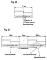
- bit clock After detecting a valid falling edge the bit clock is aligned to the bit stream as seen in Figure 26.
- the first sample of the next bit is determined by the central sample of the voting window.
- the detection window can comprise any number of samples, in particular an even number of samples.
- the detection window comprises an odd number of samples. This allows an unambiguous majority voting.
- the detection window is positioned at an expected edge between two bit cells of the bit stream in order to comprise at least one samples of a first bit cell and at least one sample of a subsequent bit cell with the respective sample values and that the method is used for bit edge detection.
- An edge detection window determines the time window in which the next edge for bit clock alignment is expected. This window is set during frame reception around the expected logical '1' to '0' transition between two consecutive bits of a BSS (Byte Start Sequence) signal.
- BSS Bit Start Sequence
- the detection window is centered on an expected center of a bit cell of the bit stream in order to comprise at samples only of said bit cell and that the method is used for detecting a bit value of said bit cell.
- the actual bit value of a bit cell is not determined from a single sample value. Rather, a number of sample values are acquired and the actual bit value is determined by means of the majority voting over the acquired samples.
- the detection window for detecting a bit value comprises 6 samples.
- the method according to the present invention is used for filtering out glitches or spikes in the bit stream.
- the majority voting over the acquired samples of a bit cell has the effect that glitches or spikes within the bit stream are filtered out.
- the detection window For positioning the detection window on a bit cell within the bit stream, appropriate parameters can be predefined according to which the detection window is positioned. It is suggested that the detection window is positioned on the expected center of a bit cell according to a predetermined offset-parameter and to a predetermined parameter specifying the number of samples in the detection window.
- the offset-parameter specifies the distance from the beginning of the bit cell to the beginning of the detection window.
- the parameters have a time entity, in particular numbers of samples.
- the above-mentioned object is achieved by a computer program of the above-mentioned kind, characterized in that, the computer program is programmed in order to execute a method according to the present invention.
- the computer program is storable on a read-only-memory (ROM), on a random-access-memory (RAM) or on a flash-memory.
- ROM read-only-memory
- RAM random-access-memory
- flash-memory a flash-memory
- bit stream decoding unit of the above-mentioned kind characterized in that it comprises:
- bit stream decoding unit comprises means for executing the method according to the present invention.
- the above-mentioned object is achieved by a node of a communication system of the above-mentioned kind, characterized in that the node comprises a bit stream decoding unit according to the present invention for decoding the bit stream received from the communication media.
- the present invention refers to a dependable automotive network. Throughout the following description the following structure is followed: at the beginning of each chapter (section) the requirements for this topic are defined, afterwards more detailed descriptions are provided. In the description UPPER CASE letters are used to denote constants. All constants used in the document are listed at the end of the description.
- the objectives of the static segment are the following:
- the objectives of the dynamic segment are the following:
- the FlexRay protocol can be divided into various layers of a layer architecture comprising the following layers:
- Figure 103 shows the architecture of a node 100 (electronic control unit, ECU) of the communication system. Every node 100 consists of the five sub-components host controller 101, communication controller 102, bus guardian 103, bus driver 104, and power supply 105. In the following description the requirements for the communication controller 102, the bus guardian 103, the bus driver 104 and the interfaces to the host 101 and the power supply 105 are described.
- Figure 104 shows a possible topology configuration of the communication system 106 (network).
- a node 100 can either be connected to both channels 1 and 2 (node A, C, and E) or only channel 1 (node B) or only channel 2 (node D).
- a configuration, where all nodes 100 are connected by one channel only is also possible.
- FlexRay media access occurs within a communication cycle.
- FlexRay offers the choice of two media access schemes. These are a static time division multiple access (TDMA) scheme, and a dynamic mini-slotting based scheme.
- Communication in the communication system 106 is done in a communication cycle consisting of a static segment and a dynamic segment, where each of the segments may be empty.
- the first frame ID in a system with a static segment is ID number 1 (see Figure 105).
- SOC start of cycle
- the sending slots are represented through the ID numbers that are the same on both channels.
- the sending slots are used deterministically (in a predefined time divisional multiple access (TDMA) strategy) in the static segment.
- TDMA time divisional multiple access
- Nodes 100 that are connected to both channels send their frames in the static segment simultaneously on both channels.
- Two nodes, that are connected to one channel only, but not the same channel, may share a slot in the static segment.
- nodes 100 can participate that send frames, which are received by all other nodes (e.g., node A, C and E in Figure 104). All nodes execute the clock synchronization algorithm, but only the frames of the static segment are considered. It is possible to send different data in the same sending slot on different channels.
- the following refers to frame scheduling and multiplexing of sending slots.
- the following refers to frame and bit coding.
- the following refers to the electrical physical layer.
- the following refers to frame timing.
- the following refers to the start-up of the communication system.
- the following refers to shut-down of the communication system.
- the following refers to clock synchronization of the nodes in the communication system.
- the proper synchronization of the individual clocks of the communication controllers is a pre-requisite for the TDMA communication scheme.
- the following description refers to the FlexRay clock synchronization mechanism (based on the Fault-Tolerant Midpoint algorithm).
- the following refers to the synchronization algorithm.
- the communication system according to the present invention can be used in almost any environment. However, preferably it is used in vehicles of any kind, in particular in safety critical applications in the automotive sector. In that case the communication system has to fulfill the following automotive constraints: • Req : FlexRay devices must meet automotive temperature requirements. Comment:
- the power modes of the ECU must be sensitive to control signals from the host and wake-up signals from the transmission media, from the ECU internally (e.g., from the host) and optionally from the ECU externally (e.g., by a switch).
- the bus driver has to support several states or operating modes:
- the communication system and its components shall offer adequate error management mechanisms to deal with faults arising from the following levels:
- the communication system furthermore shall offer diagnosis information to the host computer with respect to controller, bus (channel), and incoming/outgoing link failures.
- the communication controller shall detect the following list of errors:
- the following faults have at least to be detected by the communication controller:
- Table 3 shows Communication Network Constants (Min/Max). Table 3: Definition of the constants used throughout the specification. Name Value Description CONTROLLER_MAX 64 Maximum number of controllers connected to one communication channel. CYCLE_LENGTH_MIN 250 ⁇ s Minimum length of the configurable communication cycle. CYCLE_LENGTH_MAX 64 ms Maximum length of the configurable communication cycle. DATA_BYTES_MAX 246 Maximum number of data bytes. DYNAMIC_IDS 4095 Maximum number of dynamic identifiers. STATIC_SLOTS_MIN 2 Minimum number of static slots in a static segment of a communication cycle STATIC_SLOTS_MAX 4095 Maximum number of static slots in a static segment of a communication cycle
- Bus Consists of one or several channels Bus Driver A bus driver connects a communication controller to one channel.
- Bus Guardian A bus guardian protects one channel from timing failures of the communication controller. It is therefore connected to one communication controller and one bus driver. The bus guardian must be independent from the protocol communication controller.
- byteflight Communication network developed by BMW AG, Motorola, ELMOS, Infineon, Siemens EC, Steinbeis Transfer scholar für Mitautomatmaschine, IXXAT (see www.byteflight.com) Channel
- a channel is a physical connection between several communication controllers.
- a redundant channel consists of two channels connecting the same communication controllers.
- CHI Controller Host Interface Clique Set of communication controllers having the same view of certain system properties, e.g., the global time value, or the activity state of communication controllers. Cluster Synonym for network within this specification. Cluster time Same as cycle time.
- Communication Controller A communication controller is connected to one or two channels where it can send and receive frames.
- Communication Cycle Periodic data transfer mechanism Structure and timing are statically defined. However, a static and a dynamic segment allows for the transmission of both, state and event information. Controller see, Communication Controller. CRC Cyclic Redundancy Code attached to a frame.
- CYCLE The CYCLE field is used to transmit the cycle counter. The cycle counter is increased simultaneously in all nodes by the communication controller at the start of each new communication cycle. Cycle Counter Contains the number of the current communication cycle. Cycle time Contains the time within a communication cycle in units of macroticks. Same as cluster time. DATA Data field in a frame.
- DLC Data length field Dynamic Segment Segment of the communication cycle where frames are transmitted according to a mini-slotting algorithm.
- the sending order is defined by a statically determined identifier. Identifiers with smaller numbers have priority over identifiers with higher numbers.
- a communication cycle may consist of the static segment only.
- EOF End Of Frame An optical or electrical physical layer may require different end of frame sequences.
- ECU Electronic Control Unit Same as node.
- FIFO First In First Out. Buffers can be configured to work as a FIFO memory for frames. Frame A frame consists of all information transmitted in one slot (with one identifier) on one channel. FTA Fault Tolerant Average.
- the FTA is a fault tolerant clock synchronization algorithm that is able to tolerate up to a pre-defined number k of maliciously faulty clocks. This algorithm is based on a sorted array of clock deviations. The lower and upper k clock deviation values are discarded. From the remaining clock deviation values the average value is calculated and then used for the clock correction.
- FTM Fault Tolerant Midpoint The FTM is a fault tolerant clock synchronization algorithm that is able to tolerate up to a pre-defined number k of maliciously faulty clocks. This algorithm is based on a sorted array of clock deviations. The lower and upper k clock deviation values are discarded. From the remaining clock deviation values the median value is chosen for the clock correction.
- Gateway A node may function as a gateway and connect two or more networks.
- Global time Contains the combination of cycle counter and cluster time.
- Hamming Distance Minimum distance of any two code words within a code.
- Host The host is the part of an ECU where the application software is executed, separated by the CHI from the communication network.
- ID The frame identifier defines the slot position in the static segment and defines the priority in the dynamic segment. A lower identifier determines a higher priority.
- Identifier 0 is reserved for the SOC symbol.
- the identifier of a frame must be unique within a cluster. Each controller can have one or more identifiers (in the static and the dynamic segment). Identifier see, ID . IFG Inter Frame Gap. LEN Length field of a frame. LLI Logical Line Interface.
- LSB Least Significant Bit/Byte MAC Media Access Control.
- MSB Most Significant Bit/Byte Network A network consists of a set of nodes (more than one node) connected by communication subsystem. Networks are connected by special nodes (gateways). Same as Cluster.
- Node A node may contain one or more communication controllers. Equivalent to ECU (Electronic Control Unit). Nominal Precision. The nominal precision is the clock synchronization precision that can be reached by the local clock synchronization of a cluster. NRZ Non Return to Zero physical layer coding scheme. Precision The precision is a time interval bounding the deviations between the local clocks of all active communication controllers. If a communication controllers clock deviates more than the precision from the clocks of the other controllers it must not participate in the communication any longer. Slot Duration of time during which one communication controller may access the communication medium. SOC Start of Cycle. Defines the start of a communication cycle in the pure dynamic mode, and the start of communication for start-up. SOF Start of Frame.
- An optical or electrical physical layer may require different start of frame sequences.
- Star Coupler A star coupler is connected to one channel. Static Segment Segment of the communication cycle where frames are transmitted according to a statically defined TDMA scheme. A communication cycle may consist of the static segment only. SYNC Synchronization field. This field indicates that the slot is used for clock synchronization. TDMA Time Division Multiple Access.
- xdName Time Duration Value (variable, parameter, etc.) describing a time duration, the time between two time points xtName Time Value (variable, constant, etc.) describing an instant xsName Set Set of values (variables, parameters, etc.)
- xyName[ch] Channel Specific Info Set of variables/parameters that are channel specific.
- xyName[ch] represents the pair of variables
- xyName[A] represents the variable associated with channel A
- xyName[B] represents variable associated with channel B.
- x Stands for one of c, v, g, or p above y Optionally stands for one of d, t, or s above.
- list (l) is the first element of the list "list”
- x SORT(list)
- Returns the absolute value of "a” (a if a ⁇ 0, -a if a ⁇ 0) x MODULO(a,b)
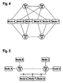
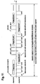
- Figure 1 shows a possible topology configuration of a communication system 106 as a dual bus.
- a node 100 can either be connected to both channels A and B (nodes A, C, and E), only to channel A (node D) or only to channel B (node B).
- a FlexRay communication system 106 can also be a single bus. In this case, all nodes 100 are connected to this bus.
- a FlexRay communication system can be built as a multiple star topology. Similar to the bus topology, the multiple-star topology can support redundant communication channels. Each network channel must be free of closed rings, and the number of star couplers must be between 1 and cStarCouplersMax , inclusive, if there are sequentially connected (cascaded) star couplers. The total number of star couplers may be more than cStarCouplersMax if there are branches in the network. Each network line connecting a node to the star coupler or between two star couplers represents a properly terminated point-to-point connection.
- the incoming signal received by the star coupler is actively driven to all communication nodes.
- FIG. 2 The configuration of a single redundant star network is shown in Figure 2.
- the logical structure (i.e., the node connectivity) of this topology is identical with that shown in Figure 1. It is also possible to create a single, non-redundant star topology which has the same logical structure as the single bus mentioned above.
- Figure 3 shows a single channel network built with three star couplers. Each node has a point-to-point-connection to one of the three star couplers. Two of the star couplers (No. 1 and 3) are directly connected to the third star coupler (No. 2).
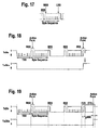
- Figure 5 shows an example of one type of hybrid topology.
- some nodes nodes A, B, C, and D
- Other nodes nodes E, F, and G
- This bus is also connected to a star coupler, allowing nodes E, F, and G to communicate with the other nodes.
- channel A is implemented as a bus topology connection
- channel B is implemented as a star topology connection.
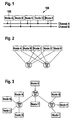
- the communication cycle is the fundamental element of the media access scheme within FlexRay. It is defined by means of a timing hierarchy .
- the timing hierarchy consists of four timing hierarchy levels as shown in Figure 7.
- the symbol window is a communication period in which one symbol out of a defined set of symbols can be transmitted on the network.
- the static segment, the dynamic segment and the symbol window form the network communication time (NCT), a period during which network wide communication takes place.
- the network idle time defines a communication-free period that concludes each communication cycle.
- the next lower level, the arbitration grid level, contains the arbitration grid that forms the backbone of FlexRay media arbitration.
- the arbitration grid consists of consecutive time intervals, called static slots
- the arbitration grid consists of consecutive time intervals, called minislots.
- the arbitration grid level builds on the macrotick level that is defined by the macrotick.
- the macrotick is specified further on.
- Specific macrotick boundaries are called action points. These are dedicated instants at which transmissions shall start (in the static segment, dynamic segment and symbol window) and shall end (only in the dynamic segment).
- the lowest level in the hierarchy is defined by the microtick that is covered further on.
- the following specifies the communication cycle for the time-triggered distributed (TT-D) mode and for the time-triggered master-controlled (TT-M) mode.
- the communication cycle for the event-triggered (ET) mode is specified futher on.
- the communication cycle for the byteflight mode is covered in the byteflight specification.
- the synchronized time triggers the execution of the communication cycle based on a periodically recurring principle with a period that consists of a constant number of macroticks.
- the communication cycles are numbered from 1 to cCycleMax. Each node shall maintain a cycle counter vCycle that shall hold the number of the current communication cycle. Initialization of the cycle counter is specified further on.
- Figure 8 illustrates the execution of the communication cycle.
- the static segment In the TT-D mode the static segment must contain at least two static slots (at least two frames must be sent with the sync bit set).
- the dynamic segment may exist optionally as well as the symbol window. Media access test, however, can only be performed if the symbol window exists.
- the static segment In the TT-M mode the static segment must contain exactly one static slot (In this slot a frame must be sent with the sync bit set). In this mode the dynamic segment must exist, while existence of the symbol window remains optional.
- Table 6 summarizes the protocol modes and the possible configurations of the communication cycle.
- Table 6 Network Communication Time Constituents vs. Protocol Modes protocol mode network communication time media access test usable static segment dynamic segment symbol window TT-D mode at least 2 static slots configured - - no configured yes at least 2 static slots configured minislots configured - no configured yes TT-M mode 1 static slot configured minislots configured - no configured no ET mode see Chapter "Event Triggered Mode" BF mode see byteflight specification WU mode no communication cycle established
- the FlexRay protocol supports clusters with a single communication channel (channel A only) or with dual communication channels (channel A and channel B).
- channel A and channel B dual communication channels
- the channels are synchronized to one another.
- nodes may be connected to either one or both of the communication channels.
- Arbitration within the network communication time is performed by means of unique frame priorities and a slot counting scheme.
- the frame identifiers may either be assigned by an off-line configuration tool or during run-time using an application based assignment strategy. Note that in all cases the uniqueness of the frame identifiers per channel must be maintained to ensure collision-free arbitration).
- the frame identifiers shall range from 1 to cSlotIDMax. The frame identifier determines in which segment and when within the respective segment a frame shall be sent.
- Each node shall maintain a slot counter vSlotCounter[ch] for each of the two respective channels.
- the slot counters shall be initialized with 1 at the start of each communication cycle. Initialization in the startup phase is specified further on.
- the static segment shall consist of gNumberOfStaticSlots static slots of equal duration.
- the number of static slots gNumberOfStaticSlots is a global constant for a given cluster and may range between 1 and cSlotIDMax .
- one static slot pSyncSlot may be configured to contain a synchronization frame, a special type of frame required for synchronization within the cluster.
- psyncSlot is a node specific value that equals the number of the static slot in which the sync frame shall be transmitted
- Figure 9 illustrates all transmission patterns that are possible for a single node within the static segment.
- the node transmits a frame on channel A and a frame on channel B.
- the node transmits a frame only on channel A (An equivalent pattern is also possible in which a node transmits a frame on channel B and no frame on channel A.
- Different nodes can share a static slot across both channels as described above).
- slot 3 no frame is transmitted on either channel.
- a frame shall be transmitted on a channel
- a frame shall be transmitted on a channel
- the frame shall be assembled as follows:
- All static slots shall consist of an equal number of gdStaticSlot macroticks.
- the number of macroticks per static slot gdStaticSlot is a global constant for a given cluster and may range between 2 and TBD.
- Each static slot contains an action point that shall be offset from the start of the slot by gdActionPointOffset macroticks. Frame transmission shall start at the action point of the respective static slot.
- the number of macroticks within the action point offset gdActionPointOffset is a global constant for a given cluster and may range between 1 and TBD.
- Figure 10 depicts the detailed timing of the static slot.
- the slot counter for channel A vSlotCounter[A] and the slot counter for channel B vSlotCounter[A] shall be incremented by one (Note that this also holds for the last static slot within the static segment).
- a dynamic mini-slotting based scheme shall be used to arbitrate transmissions.
- the duration of communication slots may vary in duration in order to accommodate frames of different length.
- the dynamic segment shall consist of gNumberOfMiniSlots minislots of equal duration.
- the number of minislots gNumberOfMiniSlots is a global constant for a given cluster and may range between 0 and tbd.
- the dynamic segment also consists of a set of consecutive dynamic slots that contain one or multiple minislots.
- the duration of a dynamic slot depends on whether or not communication, i.e. frame transmission or reception, takes place.
- the duration of a dynamic slot shall be established on a per channel basis.
- Figure 11 outlines the media access scheme within the dynamic segment.
- a frame shall be transmitted on a channel
- the frame shall be assembled as follows:
- Timing within the dynamic segment is based on minislots.
- Each minislot shall contain an equal number of gdMinislot macroticks.
- the number of macroticks per minislot gdMinislot is a global constant for a given cluster and may range between 2 and tbd .
- Each minislot contains an action point that shall be offset from the start of the minislot by gdMsActionPointOffset macroticks.
- the number of macroticks within the minislot action point offset gdMsActionPointOffset is a global constant for a given cluster and may range between 1 and tbd .
- Figure 12 shows the detailed timing of a minislot.
- Frame transmission shall start at the minislot action point of the first minislot of the respective dynamic slot. In the dynamic segment frame transmission shall also end at a minislot action point. If the frame does not end at a minislot action point by virtue of its data length, then the transmitter shall extend the transmission using the dynamic trailing sequence (DTS) as described further on.
- DTS dynamic trailing sequence
- the dynamic slot distinguishes between the transmission phase and the dynamic slot idle phase.
- the transmission phase ranges from the start of the dynamic slot to the last minislot, in which the transmission terminates.
- the dynamic slot idle phase concludes the dynamic slot.
- the dynamic slot idle phase is defined as a communication-free phase that succeeds the transmission phase in each dynamic slot. It is required to account for the communication channel idle detection latency and to process the frame by the receivers.
- Figure 13 shows the detailed timing within the dynamic segment.
- the start of the dynamic segment requires particular attention.
- the first action point in the dynamic segment shall occur after max ( gdActionPointOffset , gdMsActionPointOffset ) macroticks after the end of the static segment.
- Each node shall perform slot counter housekeeping on a per channel basis. At the end of every dynamic slot the respective slot counter vSlotCounter[ch] shall be incremented by one until either
- the respective slot counter shall be set to zero and further increments shall be suspended for the respective communication cycle.
- Constraints concerning the configuration of the dynamic segment are specified further on.
- a single symbol may be sent, i.e. either a normal symbol, an alarm symbol, a medium access test symbol or no symbol at all shall be sent.
- arbitration among different senders is not provided by the protocol for the symbol window. If arbitration among multiple senders is required for the symbol window it has to be performed by means of a higher-level protocol.
- the symbol window shall consist of a fixed number of gdSymbolWindow macroticks.
- the number of macroticks per symbol window gdSymbolWindow is a global constant for a given cluster and may range between 0 and TBD.
- the symbol window contains an action point that shall be offset from the start of the slot by gdActionPointOffset macroticks. Symbol transmission shall start at the action point within the symbol window (see Figure 15).
- Constraints concerning the configuration of the symbol window are specified further on.
- the clock correction terms shall be calculated and the offset correction term shall be applied in one or multiple macroticks. Details of the clock synchronization process are described further on.
- the network idle time shall also serve as a phase to perform implementation specific cluster cycle related tasks.
- the network idle time shall contain gdNIT macroticks.
- the number of macroticks within the network idle time gdNIT is a global constant for a given cluster and may range between 1 and TBD.
- Constraints on the duration of the network idle time are specified further on.
- FlexRay uses a Non-Return to Zero (NRZ) signaling method for coding and decoding of frames and symbols.
- NRZ Non-Return to Zero
- This section specifies the mechanisms used to encode the logical frames and symbols into a bit stream for transmission and how the transmitting node presents this bit stream to the Bus Driver for communication onto the network.
- the sender shall start the transmission of a frame or symbol by setting the TxENn signal to logical "0".
- the sender shall stop the transmission of a frame or symbol by setting the TxENn and the TxDn signals to logical "1".
- the logical frame is described further on.
- Frame coding transforms logical frames to a continuous bit stream by the following steps:
- Each byte sequence shall begin with a Byte Start Sequence (BSS).
- BSS consists of a logical "1" bit followed by a logical "0" bit.
- a byte sequence consists of a BSS followed by eight data bits from the logical frame.
- Transmission of the data bits within a byte sequence shall be such that the most significant bit of the data is transmitted first with the remaining bits of the data being transmitted in decreasing order of significance. This is shown in Figure 17.
- the purpose of the BSS is to provide bit stream timing information to receiving devices.
- the signal edge between the first and the second bit of the BSS is used to realign the bit timing of the receiver (i.e., bit clock resynchronization).
- the Transmission Start Sequence (TSS) is inserted into the bit stream before the first byte sequence.
- the TSS consists of a continuous logical "0" level.
- the duration of the TSS shall be configurable between 1 to 15 nominal bit times.
- the Frame End Sequence is appended to the bit stream following the final byte sequence.
- the FES is a two bit sequence consisting of a logical "0" bit followed by a logical "1" bit.
- DTS Dynamic Trailing Sequence
- a dynamic trailing sequence shall be transmitted immediately after the FES of a frame that is transmitted in the dynamic segment of a communication cycle.
- the purpose of this sequence is to indicate the exact point in time of the minislot action point.
- the DTS starts with a variable number of consecutive logical "0"s.
- the DTS length is greater or equal to 1 bit.
- the DTS is concluded with the transmission of a logical "1" bit. Note that the granularity of the length of the "0" portion of the DTS is microticks rather than bits. In general, the trailing "0" to "1" transition is not synchronous to a bit cell boundary.
- Figure 18 shows the entire bit stream of a frame transmitted in the static segment.
- the transmitting node shall set the TxENn signal to logical one.
- Figure 19 shows the entire bit stream of a frame transmitted in the dynamic segment.
- the TxDn output shall switch to logical "1" level, while TxENn shall switch to logical "1" one bit duration gdBit after the action point (This ensures that there is a duration of gdBit in which the TxDn output is at logical one prior to the transition of TxENn to logical one. This is required for the stability of certain types of physical layers.).
- the FlexRay communications protocol defines six symbols; each of which is represented by specific bit pattern:
- the Status Normal Symbol shall be transmitted starting with the Transmission Start Sequence (TSS) followed by 2 gdBit times at a logical "1" level, 30 gdBit times at a logical "0" level, and a final gdBit time at a logical "1" level as shown in Figure 20.
- TSS Transmission Start Sequence
- the Status Alarm Symbol shall be transmitted starting with the Transmission Start Sequence (TSS), followed by 2 gdBit times at a logical "1" level, 20 gdBit times at a logical "0" level, and a final gdBit time at a logical "1" level as shown in Figure 21.
- TSS Transmission Start Sequence
- the Collision Avoidance Symbol shall be transmitted starting with the Transmission Start Sequence (TSS), followed by 30 gdBit times at a logical "0" level as is shown in Figure 22.
- TSS Transmission Start Sequence
- the Media Access Test Symbol shall be encoded in the same manner as the CAS symbol described above.
- Event Indication Symbol shall be encoded in the same manner as the SNS symbol described above.
- the Wake-Up Symbol shall be transmitted starting with a configurable number of gdBit times at a logical "0" level ( gdWakeupSymbolTxLow ) followed by a configurable number of gdBit times at a logical "1" level (gdWakeupSymbolTxIdle).
- the WUS shall be transmitted identically to the TxD line, i.e., starting with a configurable number of gdBit times at a logical "0" level ( gdWakeupSymbolTxLow ) followed by a configurable number of gdBit times at a logical "1" level ( gdWakeupSymbolTxIdle ).
- the Wake-up symbol shall be repeated for a configurable number of times ( gWakeupPattern ).
- the minimum number of repetitions is 2.
- the configuration parameters for the WUS are described more detail below. An example with a sequence of two WUS's is shown in Figure 23.
- This section specifies the mechanisms used to perform bit stream decoding, including the relevant parameter limits and configuration parameters with this function.
- the decoding function interprets the bit stream observed at the RxDn inputs of the CC.
- the block diagram in Figure 24 shows the control flow of the receive signals through the Bit Stream Decoding (BSD) unit.
- BSD Bit Stream Decoding
- bit stream decoding processes of the individual channels on a multiple channel FlexRay node operate independently from one another. Specifically, the bit clock alignment, edge detection, sample voting, frame decoding, and symbol detection processes on the individual channels must be capable of independent operation.
- the Bit Clock Alignment function (BCA) synchronizes the local bit clock used for bit sampling and voting to the received bit stream at the RxDn input.
- the edge detection window determines the time window in which the next edge for bit clock alignment is expected. This window is set during frame reception around the expected logical "1" to "0" transition between the two bits of the next BSS.
- the initialization of the BCA is started as soon as channel idle is detected at RxDn (and signaled to the BCA via the decoder unit).
- Figure 25 shows the mechanism that determines the initial edge detection window when a frame is received. If the received bit stream is not a frame (e.g., symbol reception), the BCA shall be deactivated until the next channel idle is signaled to the BCA via the decoder unit.
- the initialization of the BCA is performed through the following steps:
- bit clock After detecting a valid falling edge the bit clock is aligned to the bit stream as seen in Figure 26.
- the first sample of the next bit is determined by the central sample of the voting window.
- the falling edge of the next BSS is expected 10 * pSamplesPerBit samples after the falling edge of the current BSS.
- the bit time window is placed symmetrically around the expected edge in the next BSS with a size of 6 samples, i.e., the next edge detection window is set from three samples before to three samples after that expected falling edge (see Figure 27).
- the resynchronization of the next bit sampling is performed according to the following rules
- This condition does not constitute a coding error.
- the next edge detection window is determined from the aligned bit clock of the current detected falling edge.
- the falling edge of the next BSS is expected 10 * pSamplesPerBit after the current detected falling edge.
- the bit time window is placed symmetrically around the expected edge in the next BSS, i.e., the next edge detection window is set from three samples before to three samples after that expected falling edge (see Figure 27).
- the bit sampling and voting function decides whether the current bit value is to be considered as logical "1" or as logical "0". This determination shall be performed on the signals RXDA and RXDB.
- the BSD unit After initialization of the CC, the BSD unit starts bit sampling immediately, i.e., the local bit clock is started immediately and the bit stream is sampled with this (unaligned) bit clock.
- the first bit is assumed to start with the first sample. Bit clock alignment starts independently as described above.
- the number of samples of a bit is configured by the parameter pSamplesPerBit.
- pSamplesPerBit can be either 8 or 10.
- Each consecutive bit is assumed to start pSamplesPerBit after it's predecessor bit.
- bit sampling is resynchronized to the received bit stream by using the aligned bit clock.
- the resynchronization of the bit sampling is only performed at the falling edges in the BSS.
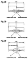
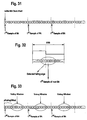
- the first sample of the next bit shall be set to the sample following the falling edge detected by the BCA. This mechanism is illustrated in Figure 32.
- bit clock alignment bit sampling is performed without resynchronization for the next ten bits, i.e., until the falling edge of the next BSS.
- the number of samples to be considered for majority voting shall be odd. It is recommended to center the voting window on the supposed center of the bit cell.
- the sample voting process defines a "window" of samples that are used to make the determination of the value of a received bit.
- This window is characterized by two parameters, pVotingOffset and pVotingSamples .
- the parameter pVotingOffset specifies the offset between the 1 st sample of the bit and the start of the voting window. This offset defines the first sample of the bit that will be considered for the voting. Specifically, the first sample considered for voting is the sample after the first pVotingOffset samples of the bit (i.e., voting starts after pVotingOffset samples have been "skipped").
- the pVotingSamples parameter specifies the number of samples in the voting window.
- the window is defined by taking pVotingSamples consecutive samples starting with the sample indicated by pVotingOffset .
- the bit value shall be determined by majority voting over the samples within the voting window (This implies that the number of samples within the voting window, pVotingSamples , must be odd.), i.e., if a majority of samples within the voting window have logical value "0", the output value of the sampled bit shall be "0"; if a majority of samples within the voting window have logical value "1” the output value of the sampled bit shall be "1".
- voting window and the bit sampling shall be resynchronized with every edge between the two bits of the Byte Start Sequence (BSS). This is the only edge to be used for the resynchronization.
- the TSS seen at the RxDn input may be shorter or longer than the TSS that was transmitted. All receivers shall accept Transmission Start Sequences with any duration in the range of 1 to 16 bit times (inclusive).
- the frame coding status shall be "valid coding", if the following conditions are met:
- the decoder unit detects an FES instead of an expected BSS, the BCA function is deactivated until channel idle is detected.
- the channel idle detection function is located in the decoder, using the input from the sampling and voting unit.
- the channel idle detection function is always active, including, for example during ongoing frame and/or symbol detection.
- channel idle detection support is not performed.
- the channel Upon exiting the CC configuration state and/or the CC low power mode, the channel shall initially be assumed to be busy (i.e. not idle). The behavior is also required when an undefined communication element is detected.
- the channel shall be considered to be idle as soon as 12 consecutive bits with the data value logical '1' have been detected.
- Presence of glitches while the channel is idle does not establish a coding error condition and there shall be no re-start of the channel idle detection timer.
- the channel idle detection counter shall be re-started when a logical "1" to "0" transition was detected where the associated bit voting result was "0".
- next start of frame or symbol is detected earlier than after successful channel idle detection then this establishes a channel idle condition violation (but not a coding error) and shall be signaled to the host.
- the coding status shall be "invalid coding".
- the CC After a valid frame or symbol is received, the CC shall perform the channel idle check. If the consecutive 12 bits after end of frame or symbol are not logical "1" a "channel idle coding violation" shall be signaled to the host.
- this condition shall be captured and be considered as a potential start of a wakeup symbol. If the wakeup condition is verified as "valid”, then the appropriate startup actions shall be performed (see below), otherwise the device shall continue to stay in sleep mode.
- the number of samples per bit pSamplesPerBit shall be configurable to either 8 or 10.
- a scalable oscillator clock period multiplier should typically be provided.
- the node shall support clock period multiplier settings (prescaler settings) of 1, 2, 4, 8, and 16. The supported bit rates depend on the oscillator frequency that is used, the prescaler setting, and the samples per bit setting.
- Table 7 Example of supported bit rates with a 12.5 ns oscillator period Index Sample Clock Prescaler Sample Clock Period (ns) Samples per Bit Bit Time (ns) Bit Rate (Mbps) 1 1 12.5 8 100 10.000 2 1 12.5 10 125 8.000 3 2 25.0 8 200 5.000 4 2 25.0 10 250 4.000 5 4 50.0 8 400 2.500 6 4 50.0 10 500 2.000 7 8 100.0 8 800 1.250 8 8 100.0 10 1000 1.000 9 16 200.0 8 1600 0.625 10 16 200.0 10 2000 0.500
- the FlexRay protocol supports two distinct frame formats:
- All controllers in a cluster must be configured to use the same frame format. Specifically, a system in which some controllers use the FlexRay frame format while other controllers use the byteflight frame format is not a valid system configuration.
- the FlexRay frame format may be used for systems in time-triggered distributed mode (TT-D mode), in time-triggered master-controlled mode (TT-M mode), or event-triggered mode (ET mode).
- T-D mode time-triggered distributed mode
- T-M mode time-triggered master-controlled mode
- ET mode event-triggered mode
- the byteflight frame format may only be used in systems operating in byteflight mode (BF mode).
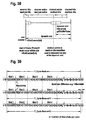
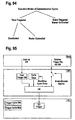
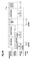
- Both frame formats contain a header segment, a payload segment and a trailer segment, each of which contains specific fields. These are described for the FlexRay and byteflight frame formats, and illustrated, respectively, in Figure 34 and Figure 35.
- the frame shall be transmitted on the network such that the header segment appears first, followed by the payload segment, and then followed by the trailer segment, which is transmitted last.
- the FlexRay header segment consists of 5 bytes that contain several distinct fields; a reserved bit, a Network Management Indication Bit, a Null Frame Indication Bit, a Sync Bit, a Frame ID field, a Payload Length field, a Header CRC field, and a Cycle Counter field. These fields are described in detail in the following sections. Within the header segment the fields shall be transmitted in the order indicated in Figure 34, moving from left to right (i.e., the Reserved bit is transmitted first and the Cycle Counter field is transmitted last).
- This field consists of one bit that is reserved for future protocol use. This bit shall not be used by the application. In a transmitting node the Reserved bit shall be set to logical '0'. In a receiving node the Reserved bit shall be ignored (The receiver uses the value of the Reserved Bit for the Frame CRC checking process, but otherwise ignores its value (i.e., the receiver shall accept either a 1 or a 0 in this field).).
- the Null Frame Indication bit fNullFrameIndicationBit indicates whether the current frame is a "null frame", i.e., a frame that contains no usable data in the payload segment of the frame.
- the Null frame indication bit indicates only whether valid data was available to the communications controller at the time the frame was sent.
- a node If a node transmits a given frame on more than one channel it shall set fSyncBit to the same value on each channel.
- This field contains the Frame Identifier for the frame.
- Each frame that may be transmitted in a cluster has a frame ID fFrameID assigned.
- Valid values for fFrameID range from 1 to 4095 (In binary: from (0000 0000 0001) 2 to (1111 1111 1111) 2 ) during the protocol operation phase (POP).
- the Frame ID 0 is an invalid Frame ID.
- the Frame ID field shall be transmitted such that the most significant bit of fFrameID is transmitted first with the remaining bits of fFrameID being transmitted in decreasing order of significance.
- Payload Length (7 bits - fPayloadLength )
- the maximum payload length is cPayloadLengthMax, which corresponds to a payload segment containing 2 * cPayloadLengthMax bytes.
- the payload field shall be less than or equal to the maximum payload length: fPayloadLength ⁇ cPayloadLengthMax.
- the payload length fPayloadLength may be different for different frames in the dynamic segment of a communication cycle.
- the payload length of a specific dynamic segment frame may vary from cycle to cycle.
- the payload lengths of a specific dynamic segment frame may be different on each configured channel. All dynamic segment frames, however, shall have 0 ⁇ fPayloadLength ⁇ cPayloadLengthMax .
- the Payload Length field shall be transmitted such that the most significant bit of fPayloadLength is transmitted first with the remaining bits of fPayloadLength being transmitted in decreasing order of significance.
- Header CRC (11 bits - fHeaderCRC )
- the Header CRC field contains a Cyclic Redundancy Check code (CRC) computed over the Sync Bit, Frame ID, and Payload Length fields of the frame.
- CRC Cyclic Redundancy Check code
- the CRC is computed in the same manner on all configured channels.
- This 11 bit CRC polynomial generates a (31,20) BCH code that has a minimum Hamming distance of 6.
- the codeword consists of the data to be protected and the CRC.
- This polynomial was obtained from T. Wadayama, Average Distortion of Some Cyclic Codes, web site available at http://vega.c.oka-pu.jp/ ⁇ wadayama/distortion.html , and its properties were verified using the techniques described in P.
- the initialization vector of the register used to generate the header CRC shall be (1A) HEX .
- the Sync Bit, the Frame ID and the Payload Length fields shall be fed into the CRC generator in network order, specifically the Sync Bit shall be shifted in first, followed by the most significant bit of the Frame ID field, followed by subsequent bits of the Frame ID, followed by the most significant bit of the Payload Length field, and followed by subsequent bits of the Payload Length field.
- the Header CRC field shall be transmitted such that the most significant bit of fHeaderCRC is transmitted first with the remaining bits of fHeaderCRC being transmitted in decreasing order of significance.
- the Cycle Counter field indicates the transmitting node's view of the cycle counter vCycle at the time of frame transmission.
- the Cycle Counter field shall be transmitted such that the most significant bit of fCycleCount is transmitted first with the remaining bits of fCycleCount being transmitted in decreasing order of significance.
- the FlexRay payload segment contains 0 to 254 bytes (0 to 127 two-byte-words) of data written by the host.
- the FlexRay Payload Segment shall consist of an even number of bytes.
- the length of the payload segment indicated by fPayloadLength correlates with the number of bytes that are sent on the communication channel. It does not necessarily define the number of bytes used by the application in the payload section. The data provided by the application may be shorter than the payload section.
- a padding function in the communication controller fills the "missing" bytes if the configured transmit buffer is smaller than the configured payload length.
- the frame CRC described below has a Hamming distance of six for payload lengths up to 248 bytes. For payload lengths greater than 248 bytes the CRC only provides a Hamming distance of four.
- the first two bytes of the FlexRay payload segment may optionally be used as a message ID field, allowing receiving nodes to filter or steer data based on the contents of this field.
- the subsequent bytes of the payload segment may optionally be used as network management vector.
- the length of the network management vector is configured by gNetworkManagementVectorLength during CC_SoftReset and cannot be changed during the protocol startup phase (PSP) or during the protocol operation phase (POP).
- gNetworkManagementVectorLength can be configured between 0 and 12 bytes, inclusive.
- the network management indication bit in the frame header indicates whether the payload section contains the network management vector (Frames that contain network management data are not restricted to containing only network management data - the other bytes in the payload section may be used to convey additional, non-Network Management data.).
- the network management vector (if present) starts with the first byte of the payload section.
- the individual bytes within the Payload Segment shall be transmitted such that the most significant bit of the byte is transmitted first with the remaining bits of the byte being transmitted in decreasing order of significance.
- the FlexRay trailer segment contains a single field, a 24-bit CRC for the frame.
- Frame CRC (24 bits - fFrameCRC )
- the Frame CRC field contains a Cyclic Redundancy Check code (CRC) computed over the Header and Payload segments of the frame.
- CRC Cyclic Redundancy Check code
- the computation includes all fields in these segments (This includes the header CRC, as well as any Communication Controller-generated "padding" bytes that may be included in the Payload segment.).
- the CRC is computed using the same generator polynomial on both channels.
- This 24-bit CRC polynomial generates a code that has a minimum Hamming distance of 6 for codewords up to 2048 bits in length and a minimum Hamming distance of 4 for codewords up to 4094 bits in length.
- This polynomial was obtained from G. Castagnoli, S. B syndromeer, and M. Herrmann, "Optimization of Cyclic Redundancy-Check Codes with 24 and 32 Parity Bits, " IEEE Trans. Commun., vol. 41, pp.
- the generation process of the CRC differs slightly depending on which channel the frame is being transmitted (Different initialization vectors are defined to prevent a node from communicating if it has crossed channels, connection of a single channel node to the wrong channel, or shorted channels (both controller channels connected to the same physical channel).):
- the frame fields shall be fed into the CRC generator in network order (that is, the first thing into the generator is the most significant bit of the Reserved Bit field, and the last thing into the generator is the least significant bit of the last byte of the Payload Segment).
- the Frame CRC field shall be transmitted such that the most significant bit of fFrameCRC is transmitted first with the remaining bits of fFrameCRC being transmitted in decreasing order of significance.
- a transmitting node may send a "null frame" which is a frame that contains no valid data in the payload segment.
- a frame is sent when a transmitter is configured to send in a given slot and channel of the static segment but is not in possession of valid data at the time when transmission of that slot is scheduled to begin. This could be caused by the host locking a transmit buffer and not releasing it before transmission time, or by a transmitter being configured for cycle counter filtering (see further on) and the current cycle counter does not match the filter.
- a Null Frame consists of
- Null frames shall only be sent in the static segment, hence the payload length is defined by gPayloadLengthStatic .
- the payload segment of a Null Frame shall be ignored by the receiver (The receiver uses the data in the Payload Segment for the Frame CRC checking process, but otherwise ignores the data.) but other fields of the frame may contain useful data (For example, the clock synchronization algorithm may make use of the arrival time of null frames with the Sync Bit field set to 1 (provided all other criteria for that frame's acceptance are met).).
- the frame shall be transmitted on the network such that the header segment appears first, followed by the payload segment, and then followed by the trailer segment, which is transmitted last.
- the byteflight header segment consists of 2 bytes that contain several distinct fields; the Frame ID, a field of reserved bits, and the frame length. These fields are described in detail in the following sections.
- the fields shall be transmitted in the order indicated in Figure 35, moving from left to right (i.e., the Frame ID field is transmitted first and the Frame Length field is transmitted last).
- This field contains the Frame Identifier for the frame.
- Each frame that may be transmitted in a cluster has a frame ID fBfFrameID assigned.
- the frame ID fBfFrameID is a unique number per communication cycle and defines the minislot in which the frame is transmitted.
- Valid values for fBfFrameID range from (0000 0001) 2 to (1111 1111) 2 .
- the Frame ID field shall be transmitted such that the most significant bit of fBfFrameID is transmitted first with the remaining bits of fBfFrameID being transmitted in decreasing order of significance.
- This field consists of four bits that may are used by the application.
- the fBfSpecialApplBits field shall be transmitted such that the most significant bit of fBfSpecialApplBits is transmitted first with the remaining bits of fBfSpecialApplBits being transmitted in decreasing order of significance.
- the fBfSpecialApplBits field in the transmitting node is written by the host (The four special application bits are written by the host of the transmitting node.
- the communication controllers on all nodes (transmitter and receiver) treat these bits as application data.).
- the Frame Length consists of a single parameter, fBfFrameLength , which indicates the number of data bytes that are contained in the payload segment of the frame.
- the frame length field does not include the number of bytes within the header and the trailer segment of the byteflight frame.
- a frame which is received with fBfFrameLength greater than 12 shall be treated as an error.
- the Frame Length field shall be transmitted such that the most significant bit of fBfFrameLength is transmitted first with the remaining bits of fBfFrameLength being transmitted in decreasing order of significance.
- the byteflight payload segment consists of 0 to 12 bytes of data written by the host.
- the individual bytes within the Payload Segment shall be transmitted such that the most significant bit of the byte is transmitted first with the remaining bits of the byte being transmitted in decreasing order of significance.
- the byteflight trailer segment consists of 2 bytes that contain two distinct fields; a Frame CRC and the Frame Completion Bit. These fields are described in detail in the following sections.
- the fields shall be transmitted in the order indicated in Figure 35, moving from left to right (i.e., the Frame CRC field is transmitted first and the Frame Completion Bit is transmitted last).
- the CRC generator polynomial shall be x 15 + x 14 + x 10 + x 8 + x 7 + x 4 + x 3 + 1
- the initialization vector of the byteflight Frame CRC shall be (00) Hex .
- the frame fields shall be fed into the CRC generator in network order (that is, the first thing into the generator is the most significant bit of the Frame ID field, and the last thing into the generator is the least significant bit of the last byte of the Payload Segment).
- the Frame CRC field shall be transmitted such that the most significant bit of fBfFrameCRC is transmitted first with the remaining bits of fBfFrameCRC being transmitted in decreasing order of significance.
- the Frame Completion Bit, fBfFCB is a single bit whose sole purpose is to allow the byteflight frame to end on a byte boundary.
- the first two bytes of the payload segment of the FlexRay frame format can be used as receiver filterable data called Message ID.
- the Frame CRC calculation is done inside the communication controller before transmission or after reception of a frame. It is part of the frame transmission process or the frame reception process, respectively.
- variable vCheckCRC_x denotes the result of the check of the consistency of a frame and its CRC for the respective communication channel. The calculation may be described by the following pseudocode.
- cCrcSize 24
- cCrcInit_x 24
- cCrcPolynomial 5D 6D CB
- the Header CRC field of a FlexRay frame is intended to provide protection against improper modification of the Sync Bit field by a faulty communication controller (CC).
- the CC that is responsible for transmitting a particular frame shall not compute the Header CRC field for that frame. Rather, the CC shall be configured with the appropriate Header CRC for a given frame by the host. This makes it unlikely that a fault in the CC that causes the value of a Sync Bit to change would result in a frame that is accepted by other nodes in the network because the CRC would not match. Removing the capability of the transmitter to generate the CRC minimizes the possibility that a message that results from a CC fault would have a proper header CRC.
- the CC that is responsible for the reception of a frame shall perform the CRC computations required to check the correctness of the Header CRC field relative to the other information that is received in the frame.
- variable vCheckHeaderCRC_x denotes the result of the check for the respective communication channel.
- the check may be described by the following pseudocode.
- the following covers the frame processing, and in particular frame reception procedure of the FlexRay protocol.
- the protocol engine related frame processing consists of three steps: The first step is called frame decoding . In this step frame decoding takes place. Frame decoding shall occur according to the decoding rules specified above. The next step is called the frame reception. In this step the syntactical correctness of the frame is assured. The last step is called frame acceptance. In this step the protocol specific data that is contained in the header of each frame such as the cycle count is checked against reference values.
- Frame reception specifies how the syntactical correctness of a frame is established.
- a frame is considered syntactically correct if no coding violations are detected during the reception of the frame, the header CRC is valid, the frame CRC is valid, and the number of bytes received corresponds to the frame length that is contained in the frame header.
- a syntactically correct frame is considered to be a correct frame ( S_CorrectFrame ).
- Figure 36 shows the frame reception state diagram.
- the transitions are summarized in Table 8.
- Table 8 Frame Reception State Transitions Transition Direction Condition for Transition Action taken on Transition from to FR_Idle FR_Active Transition of the channel state from channel idle to channel active FR_Active FR_Idle Transition of the channel state from channel active to channel idle . In this case a syntactically correct frame was received.
- the reception state machine shall remain in the FR_Idle state as long as the channel is idle. In this state the node waits for the start of a reception, which occurs once the channel becomes active. The start of a reception shall cause a transition to the FR_Active state.
- the detection of idle at the end of a syntactically correct frame shall cause a transition to the FR _ Idle state.
- the reception state machine shall remain in the FR_Abort state until the channel idle state is reached on the respective channel. Once the channel idle state is reached the reception state shall change to FR_Ready .
- the reception state machine shall remain in the FR_SoftReset state as long as the communication controller is in the CC_SoftReset state and the respective communication channel is not in the idle state.
- Frame acceptance differs depending on the current protocol phase. Whether a frame is accepted in a specific phase or not depends on the outcome of a number of checks.
- FlexRay distinguishes between the startup acceptance criteria, the static segment acceptance criteria and the dynamic segment acceptance criteria.
- the startup acceptance criteria are applied when the node is in the integration path of the startup phase.
- a frame shall be considered compliant with the startup acceptance criteria when all of the following conditions are met that are applied to a correct frame:
- a frame that complies with the startup acceptance criteria is considered to be a valid-startup frame ( S_ValidStartupFrame ).
- the static segment acceptance criteria are applied when the node is operating in the static segment prior to having the schedule in place.
- a frame shall be considered compliant with the static segment acceptance criteria when all of the following conditions are met that are applied to a correct frame:
- the dynamic segment acceptance criteria are applied when the node is operating in the dynamic segment.
- a frame shall be considered compliant with the dynamic segment acceptance criteria when all of the following conditions are met that are applied to a correct frame:
- every node has its own clock. Due to temperature fluctuations, voltage fluctuations, and production tolerances of the timing source (e.g. oscillator), the internal time base diverges between the nodes after a short time, even if all internal time bases of the nodes are started concurrently.
- the timing source e.g. oscillator
- a basic assumption for a time-triggered system is that every node in the cluster has practically the same view of time and this common global view of time is used as the local time base for each node.
- the same means that the differences between any two nodes' views of the global time are bounded to a specified tolerance limit and that the maximum value for this difference is known as the precision.
- the primary task of the clock synchronization function is to ensure the time differences between the nodes of a cluster stay within the precision.
- FlexRay supports both time-triggered and event-triggered clock synchronization. This chapter describes the time-triggered modes. Further on it is described how the event-triggered mode works. The appropriate clock synchronization mode should be chosen based upon the requirements of the applications to be supported by the cluster. The cluster must then be configured accordingly. Table 9 illustrates the cluster configuration conditions for the various clock synchronization modes.
- FlexRay supports two modes for performing time-triggered clock synchronization.
- each node individually synchronizes itself to the cluster by observing the timing of transmitted sync frames from the clock sync master.
- a FlexRay node activities shall be based on the concept global time, even though each individual node maintains its own view of it. It is the clock synchronism mechanism that differentiates the FlexRay cluster from other node collections with independent clock mechanisms.
- the global time is a vector of two values, the cycle (cycle counter) and the macrotick counter (cycle time).
- the clock synchronization can be realized with four processes called measurement, calculation, offset correction, and rate correction.
- the offset correction, measurement, and calculation processes are performed sequentially.
- Rate correction is performed in parallel to the other three.
- Figure 40 shows the relative execution timing of these four processes.
- Figure 41 illustrates the internal structure of the clock synchronization mechanism in more in detail.
- the blocks in the illustration correspond to the pseudocode procedures in this chapter.
- the black boxes describe the tasks performed and the adjacent blue text gives the corresponding procedure name. Note: For boxes with no corresponding procedure name (no blue text) there is no procedure that corresponds precisely to the task. Pseudocode fragments for these tasks are interspersed with the text.
- Every node shall measure and store, by channel, the time differences vMeasureChx (in microticks) between the expected and the observed arrival time of all sync frames received during the static segment. Difference observations are marked as invalid until the frame is received completely and has passed the required validity checks.
- the technique used for the calculation of the correction terms is a fault-tolerant midpoint algorithm (FTA/FTM).
- FTA/FTM fault-tolerant midpoint algorithm
- the algorithm works as follows (see Figure 43 and Procedure 7): 1. The measured values are sorted and the n largest and the n smallest values are discarded. 7. The value of n is adapted dynamically to the number of values in the sorted list. Table 11: FTA/FTM Term Deletion as a Function of List Size Number of Values n 1 - 2 0 3 - 7 1 8 - 16 2 8. The largest and the smallest of the remaining values are averaged for the calculation of the midpoint value. The resulting value is assumed to represent the node's deviation from the global time base and serves as the correction term (see Figure 43).
- two independent clusters can drift significantly (e.g., by the damping factor of each cluster). If synchronous operation is desired across the two clusters, external synchronization is necessary; even though the nodes within each cluster are synchronized. This can be accomplished with the synchronous application of host-deduced rate and offset correction terms to both clusters.
- External clock synchronization is an optional feature of a FlexRay controller that means is not required for any controller to meet protocol conformance. However, if this feature is used in a cluster all nodes in this cluster should support this feature in order to make it useful.
- the calculated correction values shall be checked against pre-configured limits. These limits define two regions that are referred to as the “red” and “green” regions, where the colors reflect the acceptability of the calculated value (see Figure 45). The green region is between - gRateCorrectionOut and + gRateCorrectionOut and the red region is outside these boundaries.
- the node If one of the correction values is in the red region, the node is out of synchronization. This corresponds to an error condition. Information on the handling of this situation is specified further on in the text.
- the correction terms shall be used to modify the local clock in a manner that synchronizes it more closely with the global clock. This shall be accomplished by using the correction terms to adjust the number of microticks in each macrotick.
- vRatioMicroMacro Floating-point number representing the ratio of the number of microticks to the number of macroticks per cycle.
- vRatioMicroMacro vIntegerRatio + vRest - vRemainingSumOfFractionalParts Floating-point number used for clock rate correction that indicates the total fractional microticks that have not yet been corrected by the insertion or deletion of a microtick from a macrotick. When the absolute value exceeds 1 a microtick is added or removed.
- ⁇ T vRest Floating-point number indicating the fractional portion of vRatioMicroMacro. -
- This section describes the FlexRay wakeup and startup mechanisms. Before the startup can be performed, the cluster has to be awake, so the wakeup has to be completed before startup can commence.
- the wakeup is described in more detail. Two examples are provided to give insights into the combined effort of the Hosts and communication controllers of the cluster in performing the wakeup.
- Figure 47 shows a global structure of the Wakeup.
- some nodes (possibly all but one) in the FlexRay cluster may be in a power-saving mode. At least one of those nodes that are awake may want to initiate a startup of the whole cluster. However, before a node can communicate with the other nodes, they must be awake, so the wakeup process must precede the startup process.
- the protocol defines a wakeup pattern that, if sent over the bus without error, causes all other nodes to wake up.
- the communication controller provides the Host a procedure to transmit this pattern on its channels. To limit the dangers of disturbing ongoing communication, the communication controller is only allowed to transmit this pattern on one of its possibly two connected channels at a time.
- the Host initiates the wakeup process, whereupon the communication controller monitors its channels for meaningful communication consisting of frames, wakeup symbols, or CAS symbols. The result of this monitoring determines further wakeup behavior. If nothing meaningful is received, the wakeup pattern is transmitted; otherwise the communication controller aborts the wakeup attempt with an error message to the Host. The transmission of the wakeup pattern is aborted if a collision is sensed during the transmission. In this case the communication controller monitors the channel(s) again to determine the reason for the collision.
- the FlexRay protocol does not support partial networks, i.e., networks in which some nodes are awake and some nodes are asleep. This implies that the wakeup process attempts to wake all nodes on all available channels before startup is initiated. It also implies that a cluster that is already communicating is already fully awake and does not require any further wakeup procedures.
- Figure 48 shows a structure of the Wakeup Channel Monitoring. For easier presentation, the process of listening for frames and wakeup symbols has been depicted serially, while these processes should actually run concurrently.
- the 'Wakeup channel monitoring' phase ensures that no ongoing communication is disturbed by the transmission of the wakeup pattern.
- a listen time is defined, during which the communication controller tries to detect meaningful communication on its connected channels.
- the wakeup is immediately aborted.
- a 'received frame' within this context is considered to have occurred if the S_SuccessfulHeaderReception event occurs for one of the configured channels. Since other nodes are already communicating with one another, no wakeup is necessary (whoever initiated the cluster startup ensured that all available channels are awake). The same applies if a wakeup symbol is received on the channel that the communication controller is attempting to awaken.
- a frame can be expected to follow soon after the CAS if it really was a CAS symbol and not noise, so the reception of that frame is relied upon to trigger the abort. This reduces the sensitivity of the process to noise because noise perceived as a CAS symbol does not abort the process.
- the communication controller waits for at least one channel to become idle. This reduces the risk of interrupting communication that is just received. It cannot be required that both channels in a two-channel system be idle since then a faulty, noisy channel could prevent the system wakeup.
- FIG 49 shows a structure of a Wakeup Pattern Transmission.
- the wakeup pattern consists of several repetitions of the wakeup symbol.
- the wakeup symbol (defined above) consists of an active and an idle period.
- the communication controller listens during the idle period for channel activity. If this activity exceeds a threshold, the transmission is aborted. This mechanism resolves collisions between several nodes beginning to transmit the wakeup pattern at nearly the same time. This threshold is chosen to ensure that at least one node continues transmitting the pattern. While the wakeup pattern itself is collision resilient and is still recognizable when two such patterns collide, it is this sensing in the idle period that makes the wakeup mechanism robust against any number of collisions.
- the communication controller If such a collision is sensed, the communication controller returns to the 'channel monitoring' phase. There, a collision with another wakeup pattern can be verified and signaled to the Host.
- the communication controller After successful transmission of the wakeup pattern or the abort of the wakeup attempt, the communication controller returns to its reset state and awaits instructions from the Host.
- Startup establishes a global timing scheme that - within certain bounds - is the same within all nodes in the cluster.
- the ability to calculate the proper point in time for transmitting and/or receiving each frame relies on it.
- the clock synchronization algorithm relies on this basic timing scheme so that all nodes can apply clock correction terms simultaneously (at the end of odd-numbered cycles).
- the maximum clock drift that can occur between any two nodes in the cluster within one cycle has to be known in order to configure the necessary listen timeouts.
- Figure 50 shows a global structure of startup.
- Each correctly configured node begins the startup process (after finishing the wakeup process for coldstart capable nodes) by entering the 'channel monitoring and selection of startup path' phase.
- Each node that is allowed to start up the cluster monitors its connected channels and participates in the process of selecting the initiator of the coldstart process. This process is designed to eliminate all but one sync node, which then assumes the responsibility for performing the coldstart. This coldstart initiator traverses the right path in Figure 50.
- All other nodes passively wait for the selected node to initiate communication.
- the reception of a sync frame with an even cycle counter (indicated by S_ValidEvenStartupFrame ) causes them to enter the integration path shown on the left of Figure 50.
- the node After the designated check has been successful, the node enters normal operation and is allowed to transmit data frames.
- Figure 51 shows a structure of the Channel Monitoring and Selection of a Startup Path.
- the 'startup channel monitoring' phase is similar to the channel monitoring phase of the wakeup.
- Each node listens to its connected channels and tries to recognize ongoing communication. If an S_ValidEvenStartupFrame is received, the node enters the integration path.
- the sync nodes that are allowed to start up the cluster wait for their listen time-out to expire.
- a received frame S_SuccessfulHeaderReception
- S_CASReception CAS symbol prolongs the time-out.
- the time-out expires, the node enters the coldstart path. In case no activity at all is detected, a special timeout expires and thereby enables a fast startup.
- Figure 52 shows a structure of the Selection of a ColdStart Initiator.
- nodes may enter the selection phase nearly simultaneously and transmit their CAS symbol at nearly the same time. This situation is resolved by requiring nodes in this phase to reenter the monitoring phase if they receive a sync frame or a CAS symbol. Due to the unambiguous assignment of slots to the various nodes, all nodes but one (usually the one the earliest slot) will leave this phase after at most three cycles (clock oscillator deviations may require a second or third cycle for collision resolution).
- Figure 53 shows a check on a successfully established communication.
- the coldstart initiator has transmitted three sync frames without being interrupted. Now it can expect the first replies of other sync nodes. It continues transmitting its sync frame in the designated slot.
- the coldstart initiator performs additional tests. If at least one pair of sync frames has been received, it performs the clock synchronization using these pairs (see Chapter "Clock Synchronization"). If the resulting correction values are outside specified bounds, it aborts the coldstart and reenters the monitoring phase. If the values are within the specified bounds, and at least one pair of sync frames has been received, it enters normal operation mode. This ensures that at least two sync nodes agree upon the timing schedule before any data frames may be transmitted. It enables stable clock synchronization for the two nodes and all other nodes that subsequently integrate into the now established communication.
- a counter observes how many cycles the coldstart initiator spends in the coldstart path. If too many cycles pass without this node entering the normal operation mode, startup is aborted and the node may not again try to start up the cluster. This prevents faulty nodes from persistently disturbing the startup.
- Figure 54 shows a structure of an initial synchronization. If a node in the monitoring phase receives a sync frame with even cycle counter ( S_ValidEvenStartupFrame ), it enters the integration path. The node that has transmitted the sync frame automatically becomes the reference node for the receiver.
- S_ValidEvenStartupFrame even cycle counter
- this reference node has been the reference node in a previous unsuccessful integration attempt, it is not selected and another sync frame is awaited. If no sync frame from another node is received within a specified amount of time, the previously unsuccessful reference node is given another chance.
- the integrating node sets its own cycle counter to the value received in the sync frame and awaits the sync frame of the reference node in the following odd cycle. Using this pair of frames, the integrating node corrects its clock towards the timing of the transmitter of these frames. If no sync frame with an odd cycle counter follows the even-numbered frame that triggered the integration attempt, the node aborts the integration.
- Figure 55 shows a check on a successful integration.
- the node is still not allowed to transmit any frames. It now has an understanding of time derived from its reference node.
- it listens for sync frames from all nodes, not just from its reference node.
- the node checks the timing information that it has derived from the reference node against all observable communication, considering sync frames only.
- the node counts the number of slots where it has received even/odd cycle pairs of sync frames. If no pairs have been received the node aborts the integration attempt because sync frames should have been received from the reference node if nothing else.
- the node If more than one pair has been received, the node enters the normal operation mode. If the integrating node is allowed to transmit sync frames itself and one pair of sync frames has been received, it also enters normal operation. In normal operation, i.e. during protocol operation phase, the node is allowed to transmit data and sync frames (if not configured otherwise).
- the host From the CC_SoftReset state, the host shall be able to initiate the cluster wakeup via the transition G1 (see Figure 56). For wakeup as well as for the distinct startup procedures the communication controller operates in the top-level HW state CC_Normal . Furthermore, from the CC_SoftReset state one of three distinct startup state machines shall be entered depending on how the configuration settings are chosen.
- time-triggered protocol modes mode i.e., the time-triggered distributed (TT-D) mode and the time-triggered master-controlled (TT-M) mode
- TT-D time-triggered distributed
- T-M time-triggered master-controlled
- TT-D mode For FlexRay clusters running in TT-D mode a fault-tolerant, distributed startup shall be performed. In TT-M mode a master controlled startup shall be performed, but still all mechanisms build on a time-triggered communication cycle.
- the necessary startup machine transition depends on whether a node is configured as a master node or not.
- Table 12 Global Startup State Transitions and Respective Conditions for Execution State Transition Transition Direction Condition for Transition Actions taken on Transition from to G1 CC_Soft Reset CC_Wake Up Listen soft reset released (in the respective control register) vWakeupCount, vdWakeup and vdWakeupNoise are set to zero. AND wakeup mode configured The wakeup status vector is cleared ( vWakeupFrameHead erReceived, vWakeupSymbolRece ived, vWakeupFailed and vWakeupComplete ).
- G2 CC_Startup Listen soft reset released in the respective control register) vdStartup, vdStartupNoise and AND static, mixed or dynamic mode configured ( gNumberofStaticSlots greater than or equal one) (A minimum of at least two static slots is required for a static or mixed configuration in FlexRay mode; only one static slot is configured in dynamic mode.) and vColdStartCount are set to zero.
- the startup status vector is cleared ( vCCMS, vSMMS, vOpViaColdstart, vColdstartAborted and vColdstartNoise) Error flags vMRCS and vCCLR are cleared G3 CC_byte flight Listen soft reset released (in the respective control register) AND byteflight mode configured AND slave role configured ( pMaster not set) G4 CC _ Send Symbol soft reset released (in the respective control register) AND byteflight mode configured AND master role configured ( pMaster set) G5 describe further on G6 describe further on
- Transitions W1 and W5 are described in Table 13 and transition A1 is described in Table 14.
- This section describes the wake-up path preceding the communication startup.
- Any node entering startup that has coldstart capability shall first execute the wakeup procedure. Otherwise it cannot be ensured, that the cluster is awake (or at least that the wakeup has been triggered) before the node begins the startup procedure.
- the Host completely controls the wake-up procedure.
- the communication controller provides the Host the ability to transmit a special wake-up pattern (see above) on each of its available channels. It ensures that ongoing communication on this channel is not disturbed.
- the communication controller cannot guarantee that all Nodes connected to this channel wake up due to the transmission of the wakeup pattern (For example, the transmission unit of the bus driver might be defective.), since these nodes cannot give feedback until the startup phase.
- the Host has to be aware of possible failures of the wakeup and act accordingly.
- the wakeup procedure enables single-channel devices in a two-channel system to trigger the wakeup, by only transmitting the wakeup pattern on the single channel to which they are connected. Another node then assumes the responsibility for waking the other channel. Any node that has coldstart capability must wake both channels before entering startup. Any node without coldstart capability connected to two channels must wake both channels, if it wants to wake up the cluster.
- the wakeup procedure tolerates any number of nodes simultaneously trying to wake up a single channel and resolves this situation such that only one node transmits the pattern. Additionally the wakeup pattern is collision resilient, so even in the presence of one faulty node also transmitting a wakeup pattern, the wakeup can be assured.
- the wakeup of the FlexRay system has to be initialized by a Host.
- the Host of a Node may command its communication controller to send a Tx-wakeup pattern on channel vWakeupChannel , while the communication controller itself is in the CC_SoftReset state.
- the communication controller then enters its wakeup mode and tries to transmit a Tx-wakeup pattern on the configured channel. Finally, it signals back the status of the wakeup attempt to the Host (refer to the wakeup status vector further on in the text).
- the wakeup mode of the communication controller involves three states:
- vWakeupComplet e is set in the startup status vector W6 CC_Wake up Listen Continuous 'active low' of more than gdWakeupMaxCollision detected during an idle phase of the Tx-wakeup pattern ( S_CheckWakeupCollision occurred). vdWakeup and vdWakeupListen are reset to zero.
- the CC_SoftReset state is part of the overall protocol state diagram. Only in the CC_SoftReset state can the Host configure the communication controller and initialize wakeup on channel vWakeupChannel (G1). After the wakeup, the communication controller returns into the CC_SoftReset state and signals to the Host the result of the wakeup attempt:
- the parameter gWakeupMax defines the maximum number of wakeup attempts allowed.
- the parameter vWakeupChannel defines the channel that the communication controller shall wake.
- the purpose of this state is to ensure that the transmission of the Tx-wakeup pattern does not disturb existing communication on channel vWakeupChannel.
- the counter vWakeupCount is set to zero upon transition G1 from the CC _ SoftReset to the CC _ WakeupListen state. Two timers are defined:
- Both timers are set to zero upon entering the CC_WakeupListen state.
- the vdWakeup timer expires upon reaching gdCycle + gdMaxDrift (one cycle length plus a safety margin).
- the vdWakeupNoise timer expires upon reaching the amount of time, during which the cluster is able to keep the clock synchronization within the maximum specified tolerance band.
- the vdWakeup timer is reset, whenever activity is received on either channel.
- the vdWakeupNoise timer is reset, whenever a valid CAS symbol is received on any channel ( S_CASReception occurred).
- a CAS symbol is - depending on the bitrate - rather short, so noise could be misinterpreted as a CAS symbol.
- the counter is reset when a CAS symbol is received. Only the frame following the CAS symbol will trigger the abort. Furthermore, it could be difficult to distinguish a CAS symbol from the first portion of a Tx-wakeup pattern.
- the communication controller If the communication controller receives a frame header without coding violation on any channel (indicated by S_SuccessfulHeaderReception ), it reenters the CC_SoftReset state and sets the vWakeupFrameHeaderReceived flag (W1).
- a communication controller must not transmit a Tx-wakeup pattern when ongoing communication is detected. The reception of a frame header without a coding violation is sufficiently robust for the detection of ongoing communication.
- the communication controller If the communication controller receives a valid Rx-wakeup symbol on channel vWakeupChannel , it reenters the CC_SoftReset state and sets the vWakeupSymbolReceived flag (W1). (The detection shall be more relaxed than the rigid definition of the Rx-wakeup symbol to take topology effects, collisions and different clock speeds into account.) An Rx-wakeup symbol on the other channel (if available) is ignored.
- the communication controller enters the CC_WakeupSend state (W2). All meaningful communication during startup is transmitted on both channels at the same time. By requiring one channel to be idle, it is ensured that no such transmission is interrupted by the transmission of the CAS symbol (within the uncertainty of the transmission delay). It cannot be required that both channels were idle, since one channel could be defective and noisy thereby preventing any wakeup and startup attempt.
- the communication controller reenters CC_SoftReset and sets vWakeupFailed in the wakeup status vector (W1).
- the wakeup is only aborted after reaching the maximal number of tries when a timer expires. This gives the communication controller time to listen to the network for ongoing communication or wakeup patterns after it stepped back from the CC_WakeupSend state.
- the communication controller transmits the Tx-wakeup pattern on the configured channel and checks for collisions.
- vWakeupCount is increased by one.
- the Tx-wakeup pattern as described above is sent on the channel vWakeupChannel .
- the communication controller listens for activity on the bus. If the communication controller receives more than gdWakeupMaxCollision of continuous 'active low' during an idle phase (This check is described in detail above and the occurrence of this event is signaled by S_CheckWakeupCollision .), it immediately steps back into the CC _ WakeupListen state (W6). Without this listening and aborting, not all collisions would lead to recognizable wakeup symbols (remember that the Tx-wakeup pattern itself is only resilient against collisions of up to two such patterns). The smaller pdWakeupMaxCollision is, the better the collision detection gets, but the EMC robustness degrades. A lower bound on the value might be the equivalent to 400ns for a 10Mbit/s system.
- the communication controller After a complete, non-aborted transmission of the Tx-wakeup pattern, the communication controller reenters the CC_SoftReset state and sets the vWakeupComplete flag in the wakeup status vector (W5).
- the Host Since the Host is closely involved in the wakeup of the FlexRay cluster, in this section the required Host behavior is described.
- the Host has to coordinate the bus guardian and the communication controller wakeup modes. It has to coordinate the wakeup of a two channels and to decide whether, or not, to wake a specific channel.
- the Host has to command the appropriate bus guardian to enter its wakeup mode before it commands the communication controller to perform a wakeup. After the communication controller returns to the CC_SoftReset state, the bus guardian must be commanded to leave its wakeup mode.
- Each node that is configured to perform a coldstart must perform a wakeup as described above before continuing with startup. For two-channel clusters it is generally advisable to use the procedure described below.
- FlexRay clusters in TT-D mode this includes all sync nodes that are not configured in a listen only mode.
- FlexRay clusters in TT-M mode this includes the Master Node.
- a Host that wants to perform a wakeup of the cluster has first to check its bus driver(s) to see if they have received Rx-wakeup patterns. If the bus driver of a channel did not receive an Rx-wakeup pattern, the Host must try to wake this channel.
- Each communication controller that is configured with coldstart capability relies upon its Host to have awakened the cluster prior to letting it enter the startup phase. Only the Host can ensure that the wakeup phase is completed before any startup attempt is performed.
- the Host must not wake channels whose bus drivers have received an Rx-wakeup symbol unless startup is not possible without an additional wakeup of those channels. This is done to speed up the wakeup process and to limit the amount of traffic on the channels; thereby, the number of collisions during this phase is reduced.
- the Host has to command the bus guardian (if available) of the channel vWakeupChannel to enter its wakeup mode. Then the Host uses the procedure described above to initialize a wakeup of channel vWakeupChannel .
- the communication controller may return several different status conditions that are described in the following section. Before evaluating these conditions, the Host must command the bus guardian of channel vWakeupChannel to leave its wakeup mode. If the Host does not cause the BG to leave its wakeup mode ( BG_WakeUp ), the BG leaves it after a fixed, non-configurable amount of time and enters the BG _ FailSilent mode.
- This section defines the various status conditions that the communication controller can return to the Host as outcomes of its wakeup attempt and the recommended reactions of the Host. These conditions are generally mutually exclusive, but in two-channel systems an Rx-wakeup symbol could be received on channel vWakeupChannel while a valid frame header is received on the opposite channel at the same time.
- the wakeup still fulfills its function when the exit conditions are given a precedence and are thereby made mutually exclusive (highest to lowest priority): Transmission complete, a frame header without coding violation has been received, an Rx-wakeup symbol has been received, the allowed number of wakeups has been exceeded.
- the communication controller When a frame header without coding violation is received by the communication controller on either available channel during CC_WakeupListen , the communication controller aborts the wakeup, even if channel vWakeupChannel is still silent. The Host must not configure the communication controller to perform additional wakeup attempts, since this may disturb ongoing communication. Instead, it shall configure the communication controller to enter the start-up to integrate into the already running cluster.
- the communication controller has received an Rx-wakeup symbol on channel vWakeupChannel during its CC_WakeupListen state. This means, that another Node is already waking this channel. To prevent collisions of Tx-wakeup patterns on channel vWakeupChannel , the communication controller aborts the wakeup.
- the Host shall configure the communication controller to wake this channel. Otherwise, it shall configure the communication controller to enter startup.
- the communication controller has transmitted the complete Tx-wakeup pattern on channel vWakeupChannel .
- the Host shall configure the communication controller to wake this channel. Otherwise, it shall configure the communication controller to enter startup.
- the communication controller was not able to transmit a complete Tx-wakeup pattern because each of its gWakeupMax attempts to transmit it resulted in at least gdWakeupMaxCollision occurrences of continuous 'active low' during an idle phase of the pattern.
- Two possible reasons for this are heavy EMC disturbances on the bus or a babbling node.
- the Host may use the retransmission procedure described below.
- This section describes how the Host can wake both channels of a two-channel system.
- Some events may prevent a cluster wakeup by a Tx-wakeup pattern without the transmitting communication controller being able to immediately detect it (E.g. an erroneous star that needs significantly more time to start up and to be able to forward messages.). After a defined amount of time, the Host can detect such an error when the cluster does not start up after wakeup as expected, or the Host's own communication controller's attempt to start up the cluster fails.
- the Host may then perform a retransmission of the Tx-wakeup pattern. It has to command the bus guardian (if available) of the chosen channel into its wakeup mode.
- the communication controller has to be brought into the CC_SoftReset state; then the procedure described above can be used to transmit a Tx-wakeup pattern on channel vWakeupChannel . Afterwards, the bus guardian must be commanded to leave its wakeup mode.
- a node is called a sync node if the host has set pSyncNode in the host interface. For a non-sync node, pSyncNode is set to false.
- the configuration parameter can only be set or cleared in the CC _ SoftReset state. The transmission of more than one sync frame by a node within one cycle has to be prevented by the communication controller.
- sync-Nodes shall generally not enter the CC_StartupListen state immediately after performing the wakeup unless the vColdStartInhibit flag is set.
- a communication controller without the vColdStartInhibit flag set will try to start up the cluster, but may fail, since no other communication controller may be ready to join the communication before the coldstart initiator aborts the startup attempt because it has reached the maximum number of cold start attempts allowed. (This scenario will still result in a successful start-up, as long as some of the other sync nodes are configured to initialize the start-up. The node that has woken the network and failed to start-up will still join the communication started by another node.) The Host must clear this flag after sufficient time has passed to allow the other nodes in the cluster to awaken.
- the Host can set the payload of frames that it transmits to a pattern that mimics two consecutive Tx-wakeup symbols (This applies only for NRZ coding defined above).
- the wakeup symbol has a fixed length, the number of bits necessary to construct a payload that is equivalent to two such wakeup symbols depends on the bit rate of the system. It may not be feasible to construct such a payload for every combination of allowed bit rate and static slot length (especially short ones). However, in this case it may still be possible to construct a dynamic frame with this payload if the dynamic segment is sufficiently long to allow it. Depending on the system configuration, it may even be possible to use two consecutive static frames.
- This section describes in more detail the Host-communication controller interaction for the wakeup in two typical situations. Firstly, it is described, how one Host wakes both channels of a two-channel system. Secondly, it is described, how one node connected to only one channel of a two-channel system wakes this channel and how a sync node (connected to both channels) wakes the other channel.
- Figure 58 shows a Simple Wakeup. Larger (ms range) amount of times are represented by dotted lines.
- This section describes a FlexRay system with two channels configured and operating in time-triggered distributed protocol mode. It is described how one sync-node first wakes the cluster and then performs the startup.
- Figure 59 shows a Simple Wakeup with Forwarding. Larger (ms range) amount of times are represented by dotted lines.
- This section describes a FlexRay system with two channels configured and operating in time-triggered distributed protocol mode. It is described, how first a non-sync node connected to only one channel wakes its channel, and how then a sync node forwards the Tx-wakeup pattern to the opposite channel and initiates the communication.
- Clusters operating in the time-triggered distributed (TT-D) mode follow a fault-tolerant, distributed startup strategy; for the time-triggered master-controlled (TT-M) mode this is reduced to a master controlled system behavior (refer to transitions indicated by prefix 'S'; see Figure 62).
- a cluster configured in byteflight (BF) mode or event-triggered (ET) mode performs an event driven, master controlled startup (state transitions with prefix 'B' ( byteflight ; see Figure 63) and 'E' (event driven; see the following descriptioin), respectively).
- the protocol operations related to synchronization of the running communication schedule, integration of further nodes to a running cluster, media access rules, and error handling are different for the configuration alternatives. Therefore, configuration-specific state diagrams are given in the following sections for each of these configurations, including state descriptions and state transitions.
- the cluster wake-up must precede the communication startup in order to ensure that all mechanisms defined for the startup work properly. After initial wake-up the whole network behaves like a broadcast medium.
- a node may enter communication (i.e., the CC_NormalOperation state) via the coldstart path (CC_ColdStartICW and CC _ ColdStartVCW state sequence) initiating the schedule synchronization, or via the integration path ( CC_InitSync and CC_IntegrationVCW state sequence) integrating into an existing communication schedule. Only sync nodes are allowed to enter via the coldstart path, and they have to check in advance whether there is already channel activity, or not (see below).
- the initial synchronization of the periodic TDMA schedule must be coordinated among all connected communication nodes. Since any sync node is permitted to initiate schedule synchronization, simultaneously started and conflicting attempts by different sync nodes must be resolved. Each node initially transmits a Collision Avoidance Symbol (CAS, see above) specifically for this purpose, before initiating the periodic schedule.
- CAS Collision Avoidance Symbol
- This symbol represents a kind of arbiter, which is used to resolve initial collisions of nodes simultaneously attempting to set up the communication schedule.
- Both non-sync nodes and sync nodes start passive integration via the integration path as soon as they receive sync frames from which to derive the TDMA schedule information.
- the node has to adapt its own clock to the global clock (rate and offset) and has to make its cycle time consistent with the global schedule observable at the network. Afterwards, these settings are checked for consistency with all available network nodes. Only if these checks are passed, can the node leave the integration phase and actively participate in communication.
- a sync node shall maintain two different timers supporting two timeout values, vdStartup and vdStartupNoise. The expiration of either of these timers causes the node to leave the initial sensing phase ( CC_StartupListen state) with the intention of starting up communication. Even though the following description is based on the assumption that these timers increment their values (starting with a reset value of zero), it is allowable for the implementation to choose another realization (e.g. counter decrement).
- the node local listen-timeout vdStartup shall have the same length ( gdStartup ) for each node in the system that is configured to send an initial CAS during startup (sync node).
- the upper bound gdStartup limits the listen time used by a node to determine if there is already communication between other nodes or at least one sync node actively requesting the integration of others.
- the listen-timeout must consider the maximum accumulated drift over the length of one cycle. Therefore the time-out interval gdStartup shall be constrained by the following inequality ( gdStartup is derived internally from the configuration parameters gdCycle and gdMaxDrift .
- the upper boundary for the listen timeout, vdStartupNoise is a multiple of gdStartup and is configurable using the parameter gStartupNoise .): gdStartup ⁇ gdCycle + gdMaxDrift
- the maximum allowable drift between any two clocks in the network is an important system parameter and is known at design time. This 'worst case' period has to be covered by configuring gdMaxDrift (unit: macroticks) accordingly.
- the reset of the timer vdStartup shall be performed asynchronously to the macrotick clock.
- vdStartupNoise 0. This additional timeout is used to improve reliability of the startup procedure in the presence of noise.
- the reset of the timer vdStartupNoise shall be performed asynchronously to the macrotick clock.
- the timer vdStartupNoise shall be reset upon entering the CC_StartupListen state.
- a FlexRay node shall support a listen-only mode. In listen-only mode, the node shall be able to receive all frames after successful integration to the running communication; i.e. the node is fully synchronized and performs the clock synchronization in order to keep this status. In comparison to the normal operation mode ( CC_NormalOperation state) the node does not actively participate in communication, i.e. neither symbols nor frames are transmitted.
- vListenOnly Setting vListenOnly to true while in the CC_SoftReset state configures the listen-only mode. vListenOnly cannot be set to true after leaving the CC_SoftReset state, but can be cleared at any time.
- This mode supports communication diagnosis ('monitoring') as well as dedicated wake-up strategies, which require host interaction ( vListenOnly subsequently cleared) in order to actively participate in communication after wake-up.
- sync nodes behave like non-sync nodes during startup. Specifically, this applies to the prerequisites for transitioning from CC_IntegrationVCW to CC_PassiveOperation . Passing the validation check requires that at least two different sync nodes are already synchronized and able to communicate. Please refer to the description of the validation check described below.
- a FlexRay node shall support a coldstart inhibit mode.
- coldstart inhibit mode the node shall be prevented from initializing the TDMA communication schedule. If the host has set vColdStartInhibit , the node shall not be allowed to initialize the cluster communication after having checked on existing communication, i.e. entering the coldstart path is prohibited. The node shall be allowed to integrate to a running cluster or to acknowledge another node, which initially tries to start the cluster communication.
- vColdStartlnhibit shall not restrict the node's ability to receive frames or to transmit frames.
- FIG 62 shows a Startup State Diagram - Time-Triggered Protocol Mode (TT-D and TT-M)
- a FlexRay node shall enter the CC_StartupListen state from the CC_SoftReset state when the communication controller is ready to attempt communication startup or enter a running network. If the communication controller is capable of initiating a startup attempt, the Host shall first ensure that the cluster is awake before letting the communication controller enter the CC_StartupListen state.
- sync nodes When entering the CC_StartupListen state from CC_SoftReset or re-entering from any other state of the startup state machine other than the CC_StartupListen state itself, sync nodes shall (re-)start their listen-timeout vdStartup and their listen-timeout with noise vdStartupNoise (see above).
- the global cluster constant gColdStartMax defines the number of cycles a node shall be permitted to attempt a coldstart, i.e. the number of cycles a node may reside in coldstart path. Once vColdStartCount is equal to gColdStartMax the node shall not enter the coldstart path (This could be achieved by preventing the restart of the listen-timeouts vdStartup and vdStartupNoise .). vColdStartCount is only reset upon entering the CC_StartupListen state from the CC _ SoftReset state.
- Non-sync nodes shall not enter the coldstart path, because these nodes are not allowed to initiate communication on their own. This could be achieved by several means, e.g. for non-sync nodes gColdStartMax is configured to zero, or the listen-timeouts vdStartup and vdStartupNoise are not maintained.
- vRefSync must be zero (see strategy defined in order to prevent a node from repetitively choosing a faulty node as a reference).
- fFrameID shall be stored to vRefSync, in order to store the identifier of the reference frame, and thereby a representation of the corresponding sync node for further processing (see below).
- the node shall enter the CC_ColdStartICW state.
- the reference node shall not be permanently excluded from the list of potential reference nodes. Due to a transient disturbance the integration might have failed even though the reference node operated fault-free (A corrupted sync frame might prevent the transition in CC_InitSync state or CC_IntegrationVCW state). Therefore, the following strategy shall be applied after an integration attempt has failed (see below).
- a non-sync node In TT-M mode, a non-sync node shall not perform the above-defined strategy. In TT-M mode, a single sync node, i.e. the master exists. All non-sync nodes and their synchronization are fully dependent on the master node. Therefore, this node is never excluded as a potential reference.
- vRefSync When entering the CC_StartupListen state from any other state, vRefSync is cleared (i.e., set to zero).
- the rate correction value shall be reinitialized with pMicroOverheadperCycleNom.
- sync nodes Only sync nodes shall be allowed to enter the coldstart path via the CC_ColdStartICW state.
- a node in time-triggered distributed (TT-D) mode with an "incoming link failure" shall stop transmission after a predefined interval of time. Thereby other sync nodes are enabled to take over responsibility of starting the communication for the cluster.
- T-D time-triggered distributed
- a node in time-triggered master-controlled (TT-M) mode shall not maintain the vColdStartCount counter.
- the node shall observe and assess the communication over one cycle.
- Two event counters per channel ( vValidSyncCount[ch] and vInvalidSyncCount[ch] ) shall be administrated in order to support decision-making.
- vValidSyncCount[ch] and vInvalidSyncCount[ch] shall be administrated in order to support decision-making.
- static segment acceptance criteria (refer to Chapter 'Frame Processing' above)
- a clear distinction between several possible cases can be made for each slot. These slot scenarios shall be judged and counters shall be incremented according to the following rules:
- the node shall consider itself to operate correctly and shall therefore initialize the counters vValidSyncCount[ch] accordingly (pre-set to one).
- the validation check shall be passed, if vValidSyncCount[ch] is greater than vInvalidSyncCount[ch] for all configured channels.
- the transition to CC_NormalOperation shall be only permitted, if the check is passed with vValidSyncCount[ch] >1 on at least one of the pChannel channels.
- vColdStartCount shall be incremented by one.
- vColdStartCount shall be compared to the allowed maximum gColdStartMax. If vColdStartCount is equal to gColdStartMax, the node shall re-enter the CC_StartupListen state.
- CC_ColdStartVCW the node shall execute the global clock synchronization for offset and rate according to the regular rules.
- CC_ColdStartVCW is the latest point in time the clock synchronization including measurement and correction phase has to be active.
- the node could perform clock synchronization already in the ColdStartICW state. This might be advantageous for the TT-M protocol mode and the establishment of the two-cycle based rate measurement phase.
- all sync frames shall be registered and pair-wise (sync frames with same frame identifier) evaluated for clock synchronization.
- the offset measurement phase shall be applied in accordance to the regular scheme, too.
- the node in the CC_ColdStartVCW state requires at least one additional matching pair of sync frames suitable for rate measurement (same frame identifier, consecutive occurrence in 'even/odd' cycle order), in order to fulfill one of the necessary prerequisites for entering CC_NormalOperation .
- the node in CC_ColdStartVCW Upon reception of two valid, matching frames ( S_ValidStaticFrame ) in even/odd cycle order, the node in CC_ColdStartVCW shall increment the counter vSyncPairs . As long as the node does not receive a response, it performs the clock correction based on one "pair of matching sync" frames, namely its own transmissions (this is taken into account by using the value 0 as 'measurement sample').
- the introduction of vSyncPairs is done in order to ease the description of several distinctions to be made in the specification. As an auxiliary variable, it is not required that this parameter is used for an implementation of a FlexRay protocol controller. With the beginning of each rate measurement phase in CC_ColdStartVCW state, the counter vSyncPairs shall be reset to zero.
- the quality of the resulting correction terms for clock synchronization shall be assessed.
- the node is only permitted to execute transition into the CC_NormalOperation state if the correction terms for both rate and offset are within the configured limits
- the node shall re-enter the CC_StartupListen state.
- a node shall enter CC_InitSync after having received an S_ValidEvenStartupFrame on one of the configured pChannel channels in the CC_StartupListen state. In the CC_InitSync state, the node shall not schedule any transmission.
- the node variable vRefSync shall contain the frame identifier of the sync frame that has been used to enter the integration path. The sync node corresponding to this reference frame is called the reference node.
- an initial rate correction value shall be determined in order to adjust the local macrotick timing to the timing given by the reference node (referred to as "rate adoption" ). To accomplish this, the time between the initial occurrence of the reference frame and its next occurrence is measured and the difference from the nominal cycle length shall be applied as the rate correction term.
- the node shall remain in the CC_InitSync state if the rate adoption can still be based on the other channel, i.e. on channel B.
- This requires the correct reception of a valid pair of S_ValidStartupFrame (starting with S_ValidEvenStartupFrame ) on the second channel.
- a pair of frames shall be constituted out of measurements picked from different channels, i.e. cross-channel measurement is prohibited.
- the node shall administer means to ensure that a transition back into the CC_StartupListen state is performed, if
- the node shall run with the corrected rate (direct application of the correction term).
- S_ValidOddStartupFrame shall be used to determine the nominal schedule position. This operation shall be based on the received identifier fFrameID .
- the node shall set its local cycle time accordingly, i.e., it shall synchronize the micro- and macrotick counters to the first BSS (falling edge) of the received sync frame.
- the cycle counter value fCycleCount of the received sync frame shall be extracted and used to initialize the local cycle counter.
- the local schedule is established according to the information derived from the reference node.
- the node shall follow the local schedule until the end of the current cycle without transmitting actively.
- the node In the CC_IntegrationVCW state, the node shall not schedule any transmission.
- the node shall confirm the settings copied from the reference node with the overall network communication scheme. For this purpose the node shall perform a cycle-based validation check similar to the check defined for the CC_ColdStartVCW state (see above). Since the node still behaves passively, the initialization of the administered counters differs from that for a node in CC_ColdStartVCW (which transmits a sync frame and thus participates actively in the validation check).
- the validation check counters shall be initialized for all configured pChannel channels upon each new cycle start as follows:
- CC_NormalOperation can only take place if the validation check has been passed, but additionally further conditions must be satisfied (see clock correction term assessment and next paragraphs, respectively).
- the validation check shall run concurrently with these additional checks until the validation check itself fails or a state transition due to another condition is executed.
- a regular measurement phase for the next rate correction term shall be started.
- all sync frames shall be registered and pair-wise (sync frames with same frame identifier) evaluated for clock synchronization.
- the offset measurement phase shall be applied in accordance to the regular scheme, too. This means that for each cycle with an odd cycle counter value the related sync frames are used to determine next offset correction term.
- the counter vSyncPairs shall be evaluated at the end of an odd cycle.
- variable vSyncPairs shall be reset to zero.
- the node has to re-enter CC_StartupListen.
- the node shall remain in the CC_IntegrationVCW state, but shall not transit into the CC_NormalOperation state.
- the next offset correction term has to meet the regular pOffsetCorrectionOut limit. That means the described exception is only made once, i.e., when the first offset correction term is available.
- a flag vOffsetOut shall be set to true once the initial offset correction term check has been performed.
- the introduction of vOffsetOut is done in order to ease the description in the specification.
- This flag shall be always evaluated, if a new offset correction term should be checked against the configured limit settings.
- the flag vOffsetOut is initialized to false, if CC_IntegrationVCW is entered from the CC_InitSync state.
- the startup phase is finished for a cluster in TT-D protocol mode.
- the single sync node In TT-M protocol mode, the single sync node enters the CC_NormalOperation state without any communication counterpart. This is due to its master role in the time-triggered master-controlled mode.
- a node In the CC_PassiveOperation state a node shall not transmit any of its configured frames. Nevertheless, the node shall not stop all activities - it shall perform clock synchronization based on the received sync frames, the reception of messages and the full support of the host interface.
- the CC_PassiveOperation state is used to support the 'listen only' protocol feature, where nodes are fully synchronized and receive all available frames (including receive buffer update), but shall not transmit anything.
- This mode shall be indicated by vListenOnly , which can be set by the host in the CC_SoftReset state only. As soon as the host clears vListenOnly, the CC_NormalOperation state shall be entered at the beginning of the next cycle.
- byteflight protocol mode For a detailed description of the byteflight protocol mode, please refer to M. Peller, J. Berwanger, and R. Greissbach, byteflight Specification, version 0.5, BMW Corporation 1999, available at http://www.byteflight.com .
- a single node that has been configured as sync master (pMaster is set) shall send a status symbol.
- the timers (of the receiver unit) shall be started according to the definitions in the byteflight specification (see M. Peller, J. Berwanger, and R. Greissbach, byteflight Specification, version 0.5, BMW Corporation 1999, available at http://www.byteflight.com ) and the node shall enter the CC_byteflightMaster state.
- a node shall send and receive messages in the CC_byteflightMaster state according to its configuration. Upon entering the CC_byteflightMaster state, i.e. after the transmission of the status symbol, the startup phase is completed. The master node does not need any acknowledgement from other nodes.
- All slave nodes ( pMaster is false) shall wait in the CC_byteflightListen state for the reception of a valid status symbol.
- All configured pChannels channels shall be independently monitored. The transition into CC_byteflightSlave and therefore the synchronization of both channels to the master shall be done on reception of the first valid status symbol. After initialization of the wait timers, all configured channels shall operate asynchronously with respect to the required frame mini-slotting on each of the pChannels channels.
- Slave nodes shall synchronize to a valid status symbol and transmit and receive messages in the CC_byteflightSlave state according to their configuration.
- a node In CC_byteflightPassive a node shall not transmit any of its configured frames. The node shall not stop all activities, but shall continue performing synchronization to status symbols (via the CC_byteflightListen state) and the reception of messages.
- the CC_byteflightPassive state is used to support the 'listen only' protocol feature, where the node shall be fully synchronized and shall receive all available frames (including receive buffer update), but shall not transmit anything.
- This mode shall be indicated by vListenOnly , which can be set by the host in the CC_SoftReset state only. As soon as the host clears vListenOnly , the CC_byteflightSlave state shall be entered with beginning of the next cycle.
- the communication controller Since the communication controller performs the transition to CC_byteflightListen state with every communication cycle, it is still synchronized to the master node. Therefore, the node is allowed to directly re-enter CC_byteflightSlave from CC_byteflightListen (at the beginning of the next cycle), if the host sets vListenOnly to false.
- the node's behavior during startup is described further on in the description.
- the node is allowed to proceed directly into normal operation ( CC_NormalOperation state) after having performed the offset measurement, correction phase, and regular rate measurement phase the first time.
- FIG. 64 depicts three nodes with two of them configured to initiate the startup actively (sync nodes A and B).
- Node C is not configured to schedule any sync frames and therefore is not allowed to enter CC_ColdStartICW .
- the first cycle counter value received by nodes B and C is in the sync frame sent by node A and it is even.
- Node A enters CC_ColdStartICW and transmits the initial CAS before any other node. Triggered by the related channel activity, node B restarts its listen-timeout vdStartup . On the reception of the CAS symbol, the listen-timeout vdStartupNoise is restarted.
- the next occurrence of node A's sync frame stops the rate measurement phase.
- Nodes B and C directly determine and apply the rate correction term to their local clock rate (i.e. to their local macrotick generation unit).
- the actual schedule position is determined based on the reference frame ID, and the micro- and macrotick timers are synchronized using the falling edge of the leading BSS of the received sync frame.
- Nodes B and C follow the current schedule until cycle end and then transition into the CC_IntegrationVCW state. Still these nodes behave passively, i.e., they do not participate the communication schedule with their own frames.
- the sync node B is allowed to enter normal operation.
- the validation checks evaluated in the CC_IntegrationVCW state are passed because on the reception of the reference sync frame vValidSyncCount[ch] is incremented, while vInvalidSyncCount[ch] remains unchanged. Consequently, with the start of next cycle, node B enters CC _ NormalOperation and starts to transmit messages according to its configuration.
- CC_NormalOperation On reception of the sync frame pair sent by another node (node B), which is synchronized to its own, the node that initially sent the CAS (node A) then enters CC_NormalOperation at the start of next communication cycle (after a whole rate measurement period has been concluded). In CC_NormalOperation all configured frames are scheduled for transmission. As soon as the node that initially sent the CAS and one other node have entered the CC_NormalOperation state, the startup phase is concluded.
- Node C enters CC_NormalOperation in the same cycle as node A, as soon as it performs the regular rate measurement phase based on 2 (or more) pairs of corresponding sync frames.
- Figure 65 shows a Startup with a collision on the CAS symbol.
- the scenario illustrated in Figure 65 depicts three nodes with all of them configured to initiate the startup actively (sync nodes).
- a collision during startup results when two sync nodes leave the CC_SoftReset state at the same, or nearly the same time.
- two nodes nodes A and B
- CC_ColdStartICW simultaneously and send their initial CAS at the same, or nearly the same time. Both nodes are then prepared to send their first sync frame.
- node A On reception of this sync frame, the other node (node A), which currently resides in the CC_ColdStartICW state, returns to CC_StartupListen and awaits the next S_ValidEvenStartupFrame .
- the figure depicts the case where a node A integrates in the sixth cycle after the cycle in which the collision occurred.
- Figure 66 shows a Startup with Validation Check in CC_IntegrationVCW Failed.
- vRefSync is cleared at the end of this cycle.
- node B and C start another integration attempt.
- both nodes finally synchronize on timing of node A.
- Node A remains in the CC_ColdStartVCW state for the entire period because it does not detect a valid response.
- Figure 67 shows a Communication Controller (CC) state transition diagram.
- Table 16 is a CC state transition table.
- Table 16 CC state transition table. State Transition Transition Direction Conditions for Transition Action taken on Transition From State To State V1 CC_PowerOff CC_PowerOn CC supply voltage rises above CC_U1 V2 CC_PowerOn CC_PowerOff CC supply voltage drops below CC_U2 L1 CC_HWReset CC_Operating CC external reset signal is inactive After hard reset (power-up reset or via dedicated reset pin) all initialization data are cleared (AND) opt.
- hard reset power-up reset or via dedicated reset pin
- Supply voltage is greater than CC_U3 for at least CC_t v3 L2 CC_Operating CC_HWReset External reset signal is active Disable ability to drive pins, all clocks halt immediately (OR) opt. Supply voltage drops below CC_U4 for at least CC_t v4 L3 CC_Operation CC_SoftReset A CC_Reset is requested by the host Immediately halt all CC internal clocks except those that are needed for operating the host interface. All configuration data shall be retained. L4 CC_SoftReset Initialization is finished L5 CC_SoftReset CC_Normal CC_SoftReset is deactivated by the host The interrupt status shall be cleared (AND) opt.
- CC optional soft checks are passed L6 Optio nal CC_SofrReset CC_Standby CC_SoftReset is deactivated AND Optional soft checks did fail L7 CC_Normal CC_ShutdownCo mplete Current communication round is finished Communication is inactive AND Host requests a shutdown (e.g. by setting the Shutdown Request bit) L8 CC_Awake CC_Standby Host issues a CC Sleep Command The ongoing frame transmission or reception will be finished and the configuration data shall be retained (OR) opt.
- Figure 68 shows a bus driver (BD) state transition diagram for an electrical BD.
- Table 17 is a BD state transition table for an electrical BD.
- For the optical bus guardian states refer to Figure 69.
- Table 17 BD state transition table (electrical BD).
- L2 BDe_Standby BDe_Normal Host commands change to BDe _ Normal State (e.g. via SPI command)
- BD has detected a valid Wakeup event (local or via bus)
- L3 BDe_Operating BDe_Sleep Host commands change to BDe_Sleep State (e.g. via SPI command)
- the transmitter will be disabled, signaling to the host OR No databus activity detected for more than BDe_t 1 OR BD Supply voltage drops below BDe_U4 for at least BDe_t v4 ( OR ) opt.
- BD junction temperature raises above BDe_K T1 °C L4
- BDe_Sleep BDe_Operating BD has detected a valid Wakeup event (local or via bus) The transmitter will be released, signaling to the host AND BD Supply voltage is above BDe_U3 for at least BDe_tv 3 ( AND ) opt.
- BD junction temperature is below BDe_K T1 °C
- optical BD behavior in various states. Conditions for entering and exiting these states are described in the table following the subsequent state diagram.
- Figure 69 shows a bus driver (BD) transition diagram for an optical BD.
- Table 18 is a BD state transition diagram for an optical BD.
- Table 18 BD State Transition Table (optical BD). State Transition Transition Direction Conditions for Conditions Action taken on Transition From State To State V1 BDo_PowerOff BDo_PowerOn BD Supply voltage raises above BDo_U1 V2 BDo_PowerOn BDo_PowerOff BD Supply voltage drops below BDo_U2 L1 BDo_Normal BDo_Sleep Host commands change to BDo_Sleep State OR No databus activity detected for more than BDo_t 1 L2 BDo_Sleep BDo_Normal Host commands change to Bdo_Normal State OR BD has detected a valid Wakeup event (local or via bus)
- the constants BDo_U1, BDo_U2 and BDo_t 1 are product specific and have to be defined in the BD product specification.
- Figure 70 shows a Bus Guardian (BG) state transition diagram.
- Table 19 is a BG state transition table.
- Supply voltage is greater than BG_U3 for at least BG_tv 3 L2 BG_Operating BG_HWReset
- External reset signal is active disable ability to drive pins, all clocks halt immediately ( OR ) opt.
- Supply voltage drops below BG_U4 for at least BG_t v4 L3 BG_Operating BG_SoftReset
- a BG_Reset is requested by the host The ongoing guarding action will be finished and the configuration data shall be retained L4
- BG_SoftReset Initialization is finished L5 SG_SoftRzset BG_Normal BG_Reset is deactivated by the host
- the interrupt status shall be cleared ( AND ) opt.
- BG optional soft checks are passed L6 Opt.
- BG_SoftReset BG_Standby Soft reset is deactivated AND BG optional soft checks did fail L7 BG_Awake BG_Standby Host issues Sleep Command L8 BG_Standby BG_Awake Host issues Wake-up Command
Landscapes
- Engineering & Computer Science (AREA)
- Computer Networks & Wireless Communication (AREA)
- Signal Processing (AREA)
- Physics & Mathematics (AREA)
- Probability & Statistics with Applications (AREA)
- Theoretical Computer Science (AREA)
- Small-Scale Networks (AREA)
- Synchronisation In Digital Transmission Systems (AREA)
- Detection And Prevention Of Errors In Transmission (AREA)
- Communication Control (AREA)
- Compression, Expansion, Code Conversion, And Decoders (AREA)
- Maintenance And Management Of Digital Transmission (AREA)
- Debugging And Monitoring (AREA)
- Closures For Containers (AREA)
- Mobile Radio Communication Systems (AREA)
- Selective Calling Equipment (AREA)
- Signal Processing For Digital Recording And Reproducing (AREA)
Abstract
Description
- The present invention refers to a method for bit stream decoding. The bit stream comprises a number of consecutive samples. The method comprises the steps of: defining a detection window comprising a number of samples; positioning the detection window at certain positions on the bit stream in order to comprise certain samples with respective sample values; applying a majority voting to the sample values comprised by the detection window in order to detect the occurrence of an edge in the bit stream; and decoding the bit stream according to the result of the majority voting and generating respective bit values.
- Furthermore, the invention refers to a computer program, which is able to run on a computer, in particular on a microprocessor.
- Further, the invention refers to a unit for decoding a bit stream. The bit stream comprises a number of consecutive samples. The bit stream decoding unit comprises means for positioning a predefined detection window at certain positions on the bit stream, the detection window being predefined in order to comprise a number of samples, the detection window being positioned in such a way as to comprise certain samples with respective sample values; means for applying a majority voting to the sample values comprised by the detection window in order to detect the occurrence of an edge in the bit stream; and means for decoding the bit stream according to the result of the majority voting and for generating respective bit values.
- Finally, the present invention refers to a node for a communication system. The communication system comprises a communication media, said node and at least one further node. The nodes are connected to the communication media for transmitting data among the nodes. The data is transmitted across the communication media in the form of a bit stream, the bit stream comprising a number of consecutive samples.
-
EP 0 412 234 A2 - Deviations of the frequency of the clock signal in respect to the frequency used for sampling and decoding the bit stream are compensated by means of a clock recovery circuit, which adds or removes pulses from the clock signal for generating corrected clock signals used for sampling and decoding. Bit edge detection and synchronization of the clock signal is performed at every zero-cross point on the base band signal, that is on every edge of the signal. The rising edge of the clock signal is synchronized on the rising edge of the zero-cross point on the base band signal.
-
GB 1 560 270 - Yang, Chih-Kong Ken et al.: "A 0.6µm CMOS 4Gb/s Transceiver with Data Recovery using Oversampling", Center for Integrated Systems, Stanford University, Stanford,
CA 94305 , USA discloses a device for bit stream decoding in which an input signal is demodulated and digital data corresponding to a demodulated input signal is recovered. The described device has a latency required for sampling and re-timing of two cycles. For recovering the bit values of a bit stream, bit boundaries are determined by detecting bit transitions of adjacent data bits. - Various types of communication systems are known in the art. Generally, they comprise a communication media, which for example is a data bus. Various nodes are connected to the communication media. Each node comprises a host controller, a communication controller, a bus driver and optionally a bus guardian. Data can be transmitted across the communication system according to various protocols. An example of such a protocol is TTCAN (Time Triggered Controller Area Network) for time triggered communication systems.
- Data transmission can be effected in communication cycles, which comprise various time slots assigned to the nodes of the communication system. Each node can send data across the communication media within the timeslot assigned to the node. Which timeslots are assigned to which nodes is part of a communication media access scheme. If a node wants to transmit data, the data is brought into a format specified in the protocol used. Formatting the data is effected by the communication controller of the node. The formatted data is called bit stream. The bit stream is forwarded from the communication controller to the bus driver, which translates the formatted data into electrical signals which then are applied to the communication media within the timeslots assigned to the node.
- A node receiving information receives the electrical signals from the communication media. The signals are transformed into the respective bit stream in the bus driver of the node. From there the bit stream is forwarded to the communication controller, where the bit stream has to be decoded.
- Decoding of the bit stream is conducted in the physical layer of the communication system. The decoding comprises in particular extracting logical frames and symbol information, and passing this information to a protocol engine of the node. In particular the following steps have to be performed during decoding of the bit stream:
- Detecting bit edges between two bit cells within the bit stream applied to the bit stream decoding unit at an input from the communication media, and
- Determining the actual value of a bit cell within the bit stream.
- Depending on the detected edges between two bit cells, in particular depending on the detected initial edge of the first bit cell within the bit stream, the decoding within the communication controller is started and data reception is activated. The communication controller itself runs on a time triggered basis, however the processing of the bits runs event triggered. Therefore, it is very important to reliably determine the initial edge of the bit cell within the bit stream. Otherwise the communication controller is started to no purpose.
- It is an object of the present invention to provide a possibility of fast and in particular reliable decoding of a bit stream.
- To solve this object according to the present invention a method of the above mentioned kind is suggested, characterized in that
- the bit stream is assembled out of byte sequences, each comprising a byte component and a Byte Start Sequence at the beginning of each byte component;
- the Byte Start Sequence comprising a logical "1" bit followed by a logical "0" bit;
- a falling edge between the logical "1" bit and the logical "0" bit of the Byte Start Sequence is detected by means of the majority voting; and
- the bit clock is aligned to the dedicated falling edge.
- Typically, in a FlexRay communication system, a bit comprises 8 or 10 samples, respectively, a bit cell comprises 8 or 10 sample values.
- The method begins with detecting a valid bit edge. This is done in the Bit Clock Alignment function (BCA). The BCA function is started as soon as an idle state of a channel, across which the bit stream is transmitted, is detected. The detection of channel idle is detected at an input (RxDn) of the Bit Stream Decoding (BSD) unit. As soon as a valid edge is detected, the detection window is positioned on the bit stream in order to detect further bit-edges and to determine the actual value of a bit cell within the bit stream.
- In particular, the Bit Clock Alignment function (BCA) synchronizes the local bit clock used for bit sampling and voting to the received bit stream at the RxDn input.
- The edge detection window determines the time window in which the next edge for bit clock alignment is expected. This window is set during frame reception around the expected logical "1" to "0" transition between the two bits of the next BSS.
- The initialization of the BCA is started as soon as channel idle is detected at RxDn (and signalled to the BCA via the decoder unit). Figure 25 shows the mechanism that determines the initial edge detection window when a frame is received. If the received bit stream is not a frame (e.g., symbol reception), the BCA shall be deactivated until the next channel idle is signalled to the BCA via the decoder unit.
- The initialization of the BCA is performed through the following steps:
- Falling edge detection (potential start of a frame, i.e., the start of a TSS)
- Rising edge detection (potential start of BSS)
- Falling edge detection (potential falling edge in the middle of the BSS)
- Alignment of bit stream to that falling edge
- First edge detection window determination
- After channel idle the BCA waits for a falling edge that is potentially the start of a frame (TSS). In order to filter out glitches, a continuous number of pVotingSamples samples are taken for majority voting to validate the occurrence of the edge (see Figure 25 with pVotingSamples = 3).
- If the majority of pVotingSamples consecutive samples is logical "0", a valid falling edge has been detected.
- After detecting a valid falling edge the BCA waits for a rising edge that is potentially the start of a BSS. In order to filter out glitches, a continuous number of pVotingSamples samples are taken for majority voting to validate the occurrence of the edge (see Figure 25 with pVotingSamples = 3).
- If the majority of pVotingSamples consecutive samples is logical "1", a valid rising edge has been detected.
- After detecting a valid rising edge the BCA waits for a falling edge that is potentially the middle of a BSS. In order to filter out glitches, a continuous number of pVotingSamples samples are taken for majority voting to validate the occurrence of the edge (see Figure 25 with pVotingSamples = 3).
- If the majority of pVotingSamples consecutive samples are logical "0", a valid falling edge has been detected.
- After detecting a valid falling edge the bit clock is aligned to the bit stream as seen in Figure 26.
- The first sample of the next bit is determined by the central sample of the voting window. Figure 26 shows an example with pVotingSamples = 3, where the second sample of the voting window shall be considered to be the first sample of the next bit. After aligning the bit sampling to this particular sample in the BSS, the first sample of each consecutive bit of the next byte is considered to occur pSamplesPerBit after first sample of the previous bit.
- Of course, the detection window can comprise any number of samples, in particular an even number of samples. However, according to a preferred embodiment of the invention it is suggested that the detection window comprises an odd number of samples. This allows an unambiguous majority voting.
- According to another preferred embodiment of the present invention it is suggested that the detection window is positioned at an expected edge between two bit cells of the bit stream in order to comprise at least one samples of a first bit cell and at least one sample of a subsequent bit cell with the respective sample values and that the method is used for bit edge detection. An edge detection window determines the time window in which the next edge for bit clock alignment is expected. This window is set during frame reception around the expected logical '1' to '0' transition between two consecutive bits of a BSS (Byte Start Sequence) signal. For example, the detection window for bit edge detection comprises 3 samples.
- According to yet another preferred embodiment of the present invention it is suggested that the detection window is centered on an expected center of a bit cell of the bit stream in order to comprise at samples only of said bit cell and that the method is used for detecting a bit value of said bit cell. According to this embodiment the actual bit value of a bit cell is not determined from a single sample value. Rather, a number of sample values are acquired and the actual bit value is determined by means of the majority voting over the acquired samples. For example, the detection window for detecting a bit value (sample voting) comprises 6 samples.
- Preferably, the method according to the present invention is used for filtering out glitches or spikes in the bit stream. The majority voting over the acquired samples of a bit cell has the effect that glitches or spikes within the bit stream are filtered out.
- For positioning the detection window on a bit cell within the bit stream, appropriate parameters can be predefined according to which the detection window is positioned. It is suggested that the detection window is positioned on the expected center of a bit cell according to a predetermined offset-parameter and to a predetermined parameter specifying the number of samples in the detection window. The offset-parameter specifies the distance from the beginning of the bit cell to the beginning of the detection window. Preferably the parameters have a time entity, in particular numbers of samples.
- Furthermore, the above-mentioned object is achieved by a computer program of the above-mentioned kind, characterized in that, the computer program is programmed in order to execute a method according to the present invention.
- According to a preferred embodiment it is suggested that the computer program is storable on a read-only-memory (ROM), on a random-access-memory (RAM) or on a flash-memory.
- Moreover, the above-mentioned object is achieved by a bit stream decoding unit of the above-mentioned kind,
characterized in that it comprises: - the bit stream is assembled out of byte sequences, each comprising a byte component and a Byte Start Sequence at the beginning of each byte component;
- the Byte Start Sequence comprising a logical "1" bit followed by a logical "0" bit;
- said means for applying a majority voting detect a falling edge between the logical "1" bit and the logical "0" bit of the Byte Start Sequence; and
- means for aligning a local bit clock used for sampling and voting to the detected falling edge.
- According to a preferred embodiment of the invention it is suggested that the bit stream decoding unit comprises means for executing the method according to the present invention.
- Finally, the above-mentioned object is achieved by a node of a communication system of the above-mentioned kind,
characterized in that the node comprises a bit stream decoding unit according to the present invention for decoding the bit stream received from the communication media. - These and other features, aspects and advantages of the present invention will become better understood with reference to the following detailed description, appended claims, and accompanying drawings, wherein:
- Figure 1
- illustrates a communication system according to the present invention with a dual channel bus configuration;
- Figure 2
- illustrates a communication system according to the present invention with a dual channel single star configuration;
- Figure 3
- illustrates a communication system according to the present invention with a single channel cascaded star configuration;
- Figure 4
- illustrates a communication system according to the present invention with a dual channel cascaded stars configuration;
- Figure 5
- illustrates a communication system according to the present invention with a single channel hybrid configuration;
- Figure 6
- illustrates a communication system according to the present invention with a dual channel hybrid configuration;
- Figure 7
- illustrates timing hierarchy levels within a communication cycle for data transmission within the communication system;
- Figure 8
- illustrates a time base triggered communication cycle for data transmission within the communication system;
- Figure 9
- illustrates possible transmission patterns for a single node within a static segment of the communication cycle;
- Figure 10
- illustrates detailed timing of a static slot within the static segment of a communication cycle;
- Figure 11
- illustrates an overview of a dynamic segment of a communication cycle;
- Figure 12
- illustrates a detailed timing within a minislot of a communication cycle;
- Figure 13
- illustrates a detailed timing within a dynamic segment of a communication cycle;
- Figure 14
- illustrates a detailed timing at the boundary between a static segment and a dynamic segment of a communication cycle;
- Figure 15
- illustrates a detailed timing within a symbol window of a communication cycle;
- Figure 16
- illustrates a sender/receiver interface of a communication controller of a node of the communication system;
- Figure 17
- illustrates a byte coding;
- Figure 18
- illustrates a frame coding in a static segment of a communication cycle;
- Figure 19
- illustrates a frame coding in a dynamic segment of a communication cycle;
- Figure 20
- illustrates a bit stream of a status normal symbol (SNS) ;
- Figure 21
- illustrates a bit stream of a status alarm symbol (SAS) ;
- Figure 22
- illustrates a bit stream of a collision avoidance symbol (CAS);
- Figure 23
- illustrates a bit stream of a sequence of two wake-up symbols (WUS);
- Figure 24
- illustrates a block diagram of a bit stream decoding unit of a node of the communication system;
- Figure 25
- illustrates a mechanism for determining an initial edge detection window when a frame is received;
- Figure 26
- illustrates a mechanism for detecting a falling edge in the middle of a first byte start sequence (BSS);
- Figure 27
- illustrates a mechanism for determining an edge detection window;
- Figure 28
- illustrates a bit clock alignment according to a first example;
- Figure 29
- illustrates a bit clock alignment according to a second example;
- Figure 30
- illustrates a bit clock alignment according to a third example;
- Figure 31
- illustrates an example of a bit sampling for bits comprising 10 samples;
- Figure 32
- illustrates a mechanism for a resynchronization of bit sampling;
- Figure 33
- illustrates an example for a bit value voting mechanism;
- Figure 34
- illustrates an overview of a FlexRay frame format;
- Figure 35
- illustrates an overview of a byteflight frame format;
- Figure 36
- illustrates a frame reception state diagram;
- Figure 37
- illustrates a frame acceptance timing in a static segment of a communication cycle;
- Figure 38
- illustrates a frame acceptance timing in a dynamic segment of a communication cycle;
- Figure 39
- illustrates a diagram with local timing of three nodes and their relation to each other;
- Figure 40
- illustrates a relative execution timing of a clock synchronization mechanism;
- Figure 41
- illustrates a node internal execution of clock synchronization procedures;
- Figure 42
- illustrates a time difference measurement (expected vs. observed arrival times);
- Figure 43
- illustrates an algorithm for clock correction value calculation;
- Figure 44
- illustrates a timing of measurement and correction;
- Figure 45
- illustrates an assessment of a calculated rate correction value;
- Figure 46
- illustrates an assessment of a calculated offset correction value;
- Figure 47
- illustrates a global structure of a wakeup procedure;
- Figure 48
- illustrates a structure of a wakeup channel monitoring procedure;
- Figure 49
- illustrates a structure of a wakeup pattern transmission procedure;
- Figure 50
- illustrates a global structure of a startup procedure;
- Figure 51
- illustrates a structure of a channel monitoring and of a selection of a startup path;
- Figure 52
- illustrates a structure of a selection of a cold start initiator;
- Figure 53
- illustrates a structure of a check on a successfully established communication;
- Figure 54
- illustrates a structure of an initial synchronization;
- Figure 55
- illustrates a structure of a check on a successful integration;
- Figure 56
- illustrates a global structure of a protocol state diagram;
- Figure 57
- illustrates a structure of a communication controller wakeup state machine of a node of the communication system;
- Figure 58
- illustrates a simple wakeup, whereas the larger amount of times within a millisecond-range are represented by dotted lines;
- Figure 59
- illustrates a simple wakeup with forwarding, whereas the larger amount of times within a millisecond-range are represented by dotted lines;
- Figure 60
- illustrates a listen-timeout of a first timer value vdStartup;
- Figure 61
- illustrates listen-timeouts of a second timer value vdStartupNoise;
- Figure 62
- illustrates a startup state diagram in a time triggered protocol mode;
- Figure 63
- illustrates a startup state diagram in a byteflight protocol mode;
- Figure 64
- illustrates a diagram of a collision-free startup;
- Figure 65
- illustrates a diagram of a startup with a collision on a collision avoidance symbol;
- Figure 66
- illustrates a diagram of a startup with a validation check in a CC_IntegrationVCW state failed, in which state a node of the communication system does not schedule any transmission;
- Figure 67
- illustrates a state transition diagram of a communication controller of a node of the communication system;
- Figure 68
- illustrates a state transition diagram of a bus driver of a node of the communication system (the optical bus guardian states are not shown);
- Figure 69
- illustrates a state transition diagram of an optical bus driver of a node of the communication system;
- Figure 70
- illustrates a state transition diagram of a bus guardian of a node of the communication system;
- Figure 71
- illustrates a state transition diagram of an active star communication system topology;
- Figure 72
- illustrates an error management state transition diagram for a time-triggered distributed protocol mode and a time-triggered master-controlled protocol mode;
- Figure 73
- illustrates an error management state transition diagram for a byteflight protocol mode;
- Figure 74
- illustrates a conceptual architecture of a controller host interface of a node of the communication system;
- Figure 75
- illustrates a state diagram of a controller host interface;
- Figure 76
- illustrates interactions of controller host interface services with controller host interface elements;
- Figure 77
- illustrates a bus driver - communication controller interface of a node of the communication system;
- Figure 78
- illustrates a bus driver - bus guardian interface;
- Figure 79
- illustrates behavior of two signals RxD and RxEN for receiving a data frame transmitted in a static segment of the communication cycle according to a first example;
- Figure 80
- illustrates behavior of two signals RxD and RxEN for receiving a data frame according to a second example;
- Figure 81
- illustrates required timing of two signals TxD and TxEN for transmitting a data frame;
- Figure 82
- illustrates a block diagram of a bus guardian - communication controller interface;
- Figure 83
- illustrates a bus guardian schedule overview;
- Figure 84
- illustrates a bus guardian - communication controller timing during a static segment of a communication cycle;
- Figure 85
- illustrates a bus guardian - communication controller timing at the beginning of a dynamic segment of a communication cycle according to a first example;
- Figure 86
- illustrates a bus guardian - communication controller timing at the beginning of a dynamic segment of a communication cycle according to a second example;
- Figure 87
- illustrates a bus guardian - communication controller timing during a bus guardian symbol window and a bus guardian watchdog disable time;
- Figure 88
- illustrates a structure of a bus guardian schedule monitor;
- Figure 89
- illustrates a bus guardian schedule monitor state machine;
- Figure 90
- illustrates interaction in a static segment of a communication cycle;
- Figure 91
- illustrates interaction in a static segment of a communication cycle with a minimum length of inter-slot gaps;
- Figure 92
- illustrates interaction in a dynamic segment of a communication cycle with a symbol window disabled;
- Figure 93
- illustrates interaction in a symbol window and in a network idle time;
- Figure 94
- illustrates FlexRay communication cycle operating modes;
- Figure 95
- illustrates an event triggered communication handling in a host controller, a controller host interface and in a communication controller of a node of the communication system;
- Figure 96
- illustrates a timing hierarchy in the view of a master node of the communication system;
- Figure 97
- illustrates a communication cycle execution from the view of a master node and a slave node;
- Figure 98
- illustrates a trigger condition in an event indication signal;
- Figure 99
- illustrates a monitoring of a trigger signal for the communication controller by a master node of the communication system;
- Figure 100
- illustrates a monitoring of an event indication signal by slave nodes of the communication system;
- Figure 101
- illustrates a protocol state diagram for an event triggered mode;
- Figure 102
- illustrates internal bus events, which are indicated externally;
- Figure 103
- illustrates an architecture of a node of the communication system;
- Figure 104
- illustrates an example for a possible network configuration;
- Figure 105
- illustrates a definition of a communication cycle with a static segment;
- Figure 106
- illustrates a definition of a communication cycle in a pure dynamic communication system;
- Figure 107
- illustrates an example for a communication scheme of two nodes of a FlexRay communication system;
- Figure 108
- illustrates a FlexRay frame format;
- Figure 109
- illustrates a byteflight frame format;
- Figure 110
- illustrates a transmission of a start sequence;
- Figure 111
- illustrates a reception of a start sequence;
- Figure 112
- illustrates a frame format for an electrical transmission on the physical layer;
- Figure 113
- illustrates a topology of a FlexRay communication system using active stars;
- Figure 114
- illustrates a topology of a FlexRay communication system using a passive bus;
- Figure 115
- illustrates a topology of a FlexRay communication system using an active star combined with a passive bus;
- Figure 116
- illustrates a block chart of an electrical active star; and
- Figure 117
- illustrates an overview of interfaces between a host controller, a communication controller, a bus driver, a bus guardian, and a power supply of a node of the communication system.
- The present invention refers to a dependable automotive network. Throughout the following description the following structure is followed: at the beginning of each chapter (section) the requirements for this topic are defined, afterwards more detailed descriptions are provided. In the description UPPER CASE letters are used to denote constants. All constants used in the document are listed at the end of the description.
- The objectives pursued in the development of the dependable automotive network are the following:
- Support of two communication paradigms, deterministic (statically defined) communication and dynamic event driven communication.
- Configurable static and dynamic part (segment) within one communication cycle. Fully static and fully dynamic configuration has to be supported.
- Flexible extendibility, even after deployment.
- High data rate and bandwidth efficiency.
- Scalable fault tolerance (i.e., single channel and dual channel operation must be supported).
- Reliable error detection (bus guardian mechanism in the time domain, cyclic redundancy check (CRC) in the value domain).
- Support of electrical and optical physical interfaces.
- Enable very low system level failure in time ratings.
- Allow use of crystal oscillators and low tolerance ceramic resonators.
- Support of active star and bus topologies.
- Low overall system cost.
- Enable re-use of carry over components without embedding knowledge of future platform partitioning.
- The objectives of the static segment are the following:
- Deterministic communication behavior in the time domain.
- Global time implemented by a fault tolerant clock synchronization algorithm.
- Immunity against accepting error-free sub-sequences of a message as valid messages (i.e. short message rejection).
- The objectives of the dynamic segment are the following:
- Event driven dynamic communication possibility.
- Flexible bandwidth allocation (for different nodes during runtime).
- No interference with the static segment.
- Support for prioritized bus access.
- Support of variable length messages with at least 200 data bytes.
- The global requirements are the following:
- Support for fault tolerance, but operation without fault tolerance must also be possible, i.e., a single bus (channel) connection must be possible for non-fault-tolerant nodes.
- The communication network has to support a system architecture, where no single fault may lead to a functional degradation.
- Protection against faults in accordance with a well-defined fault hypotheses.
- Protect against up to and including five random bit errors per frame.
- The communication protocol should be independent as far as possible from the topology.
- For highly dependable and fault-tolerant applications an independent bus guardian to prevent the monopolization of the communication medium by a communication controller is required (so called "babbling idiot").
- Errors in hardware and configuration data have to be detected during initialization and operation by error detection mechanisms (EDMs). In case a critical error is detected the controller and transceiver must not be allowed to enter normal operation or immediately abort normal operation and report an error to the host.
- Support of serviceability of system- and component-level faults.
- The bit encoding technique must not introduce data dependent changes in the length of the resulting bit stream, e.g., bit stuffing is not allowed.
- Automotive qualification of the communication controller, bus guardian, and the physical layer is required.
- Configuration data must be readable/writeable by the host. It must be possible to prohibit writing during run-time.
- Support of comprehensive self test at system communication startup.
- Support of timely and highly reliable component re-integration and system-level startup.
- Support of master-less system startup and shutdown.
- Support of traceability of system- and component-level faults to identify root causes of failures.
- Support of synchronized system shutdown without error indications.
- Support of synchronous distributed application startup and shutdown with acceptable timing and fault tolerance characteristics.
- Support of node and network moding with high security against critical inadvertant mode changes.
- Logical line compatibility to the byteflight protocol, when using an optical physical layer must be possible.
- The communication protocol for the dependable automotive network according to the present invention has the following properties:
- Synchronous and asynchronous frame transfer.
- Multi-master clock synchronization.
- Guaranteed frame latency times and jitter during synchronous transfer.
- Prioritization of frames during asynchronous transfer.
- Error detection and signaling.
- Error containment on the physical layer through an independent bus guardian device.
- Scalable fault tolerance, e.g., one controller, one/two channels, one bus guardian for each channel.
- The FlexRay protocol can be divided into various layers of a layer architecture comprising the following layers:
- The Physical Layer defines how signals are actually transmitted. Tasks of the Physical Layer are fault confinement and error detection and signaling. The Physical Layer comprises a signal level, a bit representation and a transmission medium. One task of the Physical Layer is to detect errors of the communication controller in the time domain. This is done by the so-called Bus Guardian.
- The Transfer Layer represents the kernel of the protocol. It presents frames received to the presentation layer and accepts frames to be transmitted from the presentation layer. The transfer layer is responsible for timing, synchronization, message framing, error detection and signaling, and fault confinement.
- The Presentation Layer is concerned with frame filtering and masking, frame status handling and contains the communication controller host interface.
- The Application Layer is not part of this description.
- Figure 103 shows the architecture of a node 100 (electronic control unit, ECU) of the communication system. Every
node 100 consists of the fivesub-components host controller 101,communication controller 102,bus guardian 103,bus driver 104, andpower supply 105. In the following description the requirements for thecommunication controller 102, thebus guardian 103, thebus driver 104 and the interfaces to thehost 101 and thepower supply 105 are described. - Two implementations for the
communication controller 102 are possible, one configuration of acommunication controller 102 that sends and receives on two redundant physical channels, and a second configuration which is solely connected to one physical channel. - Figure 104 shows a possible topology configuration of the communication system 106 (network). A
node 100 can either be connected to bothchannels 1 and 2 (node A, C, and E) or only channel 1 (node B) or only channel 2 (node D). A configuration, where allnodes 100 are connected by one channel only is also possible. - In FlexRay media access occurs within a communication cycle. Within one communication cycle FlexRay offers the choice of two media access schemes. These are a static time division multiple access (TDMA) scheme, and a dynamic mini-slotting based scheme. Communication in the
communication system 106 is done in a communication cycle consisting of a static segment and a dynamic segment, where each of the segments may be empty. The first frame ID in a system with a static segment is ID number 1 (see Figure 105). In a pure dynamic system with a start of cycle (SOC) symbol (see Figure 106). The sending slots are represented through the ID numbers that are the same on both channels. - The sending slots are used deterministically (in a predefined time divisional multiple access (TDMA) strategy) in the static segment. In the dynamic segment there can be differences in the phase on the two channels (see Figure 106).
Nodes 100 that are connected to both channels send their frames in the static segment simultaneously on both channels. Two nodes, that are connected to one channel only, but not the same channel, may share a slot in the static segment. - To guarantee the consistency of the clock synchronization only
nodes 100 can participate that send frames, which are received by all other nodes (e.g., node A, C and E in Figure 104). All nodes execute the clock synchronization algorithm, but only the frames of the static segment are considered. It is possible to send different data in the same sending slot on different channels. - The following constraints should be respected in the
communication system 106 according to the present invention: - The
communication controller 102 must allow to interface to an optical or an electrical physical layer. - The
communication controller 102 must support a net data rate of at least 5 Mbit/s real application data transferred per seconds under the constraints of frame overhead (including CRC) and protocol timing overhead (inter frame gap, IFG) in static communication mode. - It must be possible to connect 2 up to a
value CONTROLLER_MAX controllers 102 to one communication channel. CONTROLLER_MAX is the maximum number ofcontrollers 102 connected to one communication channel and can have a value of 64, for example. - The maximum number of slots in the static segment is set to STATIC_SLOTS_MAX. STATIC_SLOTS_MAX is the maximum number of static slots in a static segment of a communication cycle and can have a value of 4095, for example.
- The
power supply 105 for the bus driver 104 (including the bus guardian 103) and thecommunication controller 102 must meet automotive requirements. - Considering the FlexRay protocol as described in the previous part of the description the communication scheme of networked FlexRay nodes can be briefly characterized as follows:
- Each
node 100 must be able to make use of the distributed clock. - Each
node 100 must send frames inside a predefined static slot
or/and
inside the dynamic segment (collision free access) - 1st
- a
bus guardian 103 must enable the access to the bus; - 2nd
- it must be signalled that a frame should be transmitted;
- 3rd
- the transmission of the frame itself.
- Throughout the document the following notation is used:
- Req:
- Requirements
- Comment:
- contains additional descriptions and explanations
-
- Req: The communication protocol shall be independent from the data rate.
Comment:- It shall be possible to implement low end controllers e.g., 500 Kbit/s and high end controllers beyond 100 Mbit/s.
- Req: The first communication controller must support a net data rate of at least 5 Mbit/s.
Comment:- Net data rate: Real application data transferred per seconds under the constraints of frame overhead (including CRC) and protocol timing overhead (IFG) in static communication mode.
- Req: A CRC code with a Hamming Distance of at least 6 must be used.
- Req: The communication controller shall be able to operate in a current byteflight environment, i.e., the two protocol controllers have to support the same physical interface and the same representation at the logical line level. The byteflight compatibility is required for the optical physical layer only.
Comment:- Compatibility of the interfaces between host CPU and the protocol controller (CHI) is not required. The electrical physical layer does not need to support byteflight compatibility The byteflight specification can be downloaded from the following web address: www.byteflight.com.
- Data transfer in FlexRay is done in cycles, called communication cycles.
- Req: The communication cycle consists of a static and a dynamic segment as shown in Figure 105. Each of the segments may be empty, that means there are three possible configurations of the communication cycle (pure static, mixed static and dynamic (a mixed system consists of at least two static slots) and pure dynamic).
In a pure dynamic system the communication cycle starts with a SOC symbol. There are two different SOC symbols (alarm condition, normal condition). The sending slots are represented through the identifiers that are the same on both channels (see Figure 106).
The sending slots are used deterministically (in a pre-defined TDMA strategy) in the static segment. In the dynamic segment there can be differences in the phase on the two channels (see Figure 105). Nodes that are connected to both channels send their frames in the static segment simultaneously on both channels. A node that is connected to only one channel may share an identifier with another node that is only connected to the other channel.
The current communication cycle is determined by a cycle counter that is consistently incremented in every cycle (see Figure 108). - Req: The length of the communication cycle has to be stored in the configuration data.
Fit Criteria:- The maximum cycle length is defined by CYCLE_LENGTH_MAX and can have a value of 64 ms, for example.
- Req: A check mechanism has to be designed that ensures that no frame transmission is started within a certain interval so called forbidden region before the end of the communication cycle, to ensure that the beginning of the static segment in the next communication cycle is not disturbed.
- Req: Multiplexing of sending slots of one controller must be supported in such a way, that the contents of frames can be multiplexed for a certain sending slot in different communication cycles.
Comment:- So a communication matrix with nearly any possible communication patterns (periods of certain frames) based on the principle of communication cycles can be built up.
-
- Req: If the static segment of the communication cycle is not empty it consists of STATIC_SLOTS_MIN ≤ NUMBER_OF_SLOTS ≤ STATIC_SLOTS_MAX.
- Req: The static segment is subdivided into a sequence of time slots. In each of these static slots only one controller may send one frame on each channel.
Comment:- In the static segment of the communication cycle a TDMA media access strategy is used.
- Req: There is one configuration parameter for the slot length (slot_length) in the static segment, that defines this value. The length of the slots is configurable off-line but fixed during runtime.
-
- Req: In a pure dynamic system the communication cycle starts with the start of cycle (SOC) symbol.
- Req: The dynamic segment of the communication cycle consists of zero or more dynamic identifiers (slots) within the communication cycle.
- Req: Bus access in the dynamic segment is done via static frame priorities according to the byteflight specification.
- Req: In the dynamic segment the media access strategy is based on wait times (mini-slotting scheme) and the priority of identifiers. Controllers transmitting frames with higher priority identifiers send before controllers transmitting lower priority frames.
- Req: The frame length in the dynamic segment is variable during runtime.
- Req: In pure dynamic mode an external triggered SOC generation and with it the start of the communication cycle has to be supported. The timing behavior of the external trigger has to be monitored by the communication controller.
-
- Req: Two frame formats as specified below must be supported.
Comment:- The mixture of the two frame formats need not be supported, i.e., all nodes connected to a FlexRay communication system can be configured using only the FlexRay format (see Figure 108) or the byteflight format (see Figure 109).
- The following refers to the FlexRay frame format.
- Req: It must be possible to use the FlexRay format in a pure static, in a combined static and dynamic, and in a pure dynamic configuration.
- Req: The first section of the data field in a frame according to the FlexRay format must be configurable as a message ID field. This data field must be filterable by the receiver.
- In Figure 108 the following abbreviations are used:
- Res:
- Reserved bits, 4 bit, for future protocol extensions.
- ID:
- Identifier, 12 bit, value domain: (110 ... 409510), defines the slot position in the static segment and defines the priority in the dynamic segment. A lower identifier determines a higher priority. The identifier of a frame must be unique within a cluster. Each controller can have one or more identifiers (in the static and the dynamic segment).
- SYNC:
- Synchronization field, 1 bit, indicates that the slot is used for clock synchronization.
- DLC:
- Data length code field, 7 bit, DLC * 2 = number of data bytes (010, 210,..., 24610).
- H-CRC:
- 9 Bit Cyclic Redundancy Check - Sequence. The H-CRC is calculated over the SYNC- and DLC-field.
- NF:
- Null frame indication field, 1 bit, indicates that the corresponding data buffer is not updated by the host before sending.
- CYCO:
- Cycle Counter, 6 bit, the cycle counter is increased simultaneously in all nodes by the controller at the start of each new communication cycle.
- Message ID:
- The Message ID field is configurable to be used as the message identifier or as the first two data bytes.
- D0 ... D246:
- Data bytes, 0-246 bytes.
- CRC:
- 24 Bit Cyclic Redundancy Check - Sequence. The CRC is calculated over the complete frame.
- The following refers to the byteflight frame format (see Figure 109).
- Req: The byteflight frame format must be supported for pure dynamic configurations.
- In Figure 109 the following abbreviations are used:
- ID:
- Identifier, 8 bit, value domain: (110 ... 25510), defines the priority in the dynamic segment. A lower identifier determines a higher priority. The identifier of a frame must be unique within a cluster. Each controller can have one or more identifiers.
- Res:
- Reserved bits, 4 bits, for future protocol extensions.
- LEN:
- Length field, 4 bit, LEN = number of data bytes (010 ... 1210), a value higher than 12 is handled as LEN=12.
- D0 ... D11:
- Data bytes, 0-12 Bytes
- CRC:
- 15 Bit Cyclic Redundancy Check - Sequence (x15 + x14 + x10 + x8 + x7 + x4 + x3 + 1).
- FCB:
- Fill completion bit: an additional bit is added to the 15 bit CRC to fill the complete word. The bit is set to "0" as LSB.
- The following refers to frame scheduling and multiplexing of sending slots.
- Req: The cycle counter can be used to distinguish between different frame contents.
Comment:- For a sending slot different send and receive buffers can be defined in different cycles (slot multiplexing).
- The cycle counter can be used as a logical extension to the identifier (in the case of multiplexing).
- The following refers to frame and bit coding.
- Req: The coding algorithm in the communication controller has to be robust against: - glitches
- The following refers to the optical physical layer.
- Req: The controller must support at least the byteflight optical bit encoding.
Comment:- In byteflight, frames on the communication media are composed of individual bytes consisting of a start bit, eight data bits and a stop bit.
In addition, transmission of each frame begins with a start sequence consisting of 6 logical "0"-bits. This is illustrated by the diagram in Figure 110. Due to certain effects in the optical transmission, it is possible for the start sequence to be become shorter or longer during optical transmission. This is why the receiver accepts start sequences in the region of 1 to 9 logical "0"-bits. This is illustrated by the diagram in Figure 111.
- In byteflight, frames on the communication media are composed of individual bytes consisting of a start bit, eight data bits and a stop bit.
- The following refers to the electrical physical layer.
- Req: Frames on the communication media for the electrical physical layer are composed as shown in Figure 112. The frame end sequence may be empty.
- Req: A suitable bit coding scheme has to be selected, in accordance to bandwidth efficiency and electromagnetic compatibility (EMC) requirements.
- The following refers to frame timing.
- Req: Frame timing of different communication controller implementations must be interoperable.
-
- Req: Looking at the frame timing for the static segment, the reception start window shall be defined in relation to the precision. I.e., the start window must be greater than the precision.
Comment:- The actual value for the reception start window must be defined in the implementation specification.
- Req: In the static segment accurate timing requirements have to be ensured for correct frame reception. Frames may only start within the reception start window.
Comment:- The length of the frame determines the frame duration. Correct reception is given if the respective frame does not violate the temporal borders given by the access scheme. The judgement of temporal correctness is based on a rigid timing scheme.
- Req: The time difference between the predicted start StartNom and the observed start of the frame (SOF) is used by the clock synchronization algorithm.
- Req: The length of the inter frame gap (IFG) has to be minimized, in order to optimize the net communication rate.
-
- Req: Looking at the frame timing for the dynamic segment, the frame timing in the dynamic segment must be defined due to the byteflight specification.
- The following refers to the start-up of the communication system.
- Req: For each configuration (Pure Static, Pure Dynamic and Mixed Systems) the start-up of the communication network has to be possible as soon as two nodes are able to communicate.
- Req: The integration of controllers that are powered on later must not disturb the start-up procedure of the other nodes.
- Req: The start-up and re-integration of controllers shall not disturb the normal operation of the network.
- Req: The worst-case start-up time under the fault conditions given above has to be provided and guaranteed by the supplier of the communication controller. The communication network must be operational after 100 ms.
Comment:- The application designer has to consider the start-up time during the determination of the configuration parameters. Typical automotive applications require a worst case startup time of 100ms. For system configurations with extremely long communication cycles longer startup times are acceptable.
- Req: During start-up a communication controller sets the cycle counter according to the value in the received frame. The cycle time is derived from the frame ID and set accordingly.
- Req: The startup must work without reliance on collision detection.
Comment:- Collisions can occur on the bus during start-up and in the case of faults. In star topologies collision detection is not always feasible.
-
- Req: The start-up has to work as a distributed algorithm.
- Req: Only controllers that participate in clock synchronization (sync bit set) are allowed to start up the system.
Comment:- In a dual channel system only controllers connected to both channels are allowed to execute the start-up in a heterogeneous topology (mixing controllers with single channel and controllers with dual channel).
- Controllers connected to only one channel are not allowed to start-up the bus because they may corrupt the traffic of this channel in case of an incoming-link failure by sending frames after the listen-timeout (listen_timeout).
- Req: The start-up of the communication network, the integration of nodes powered on later and the re-integration of failed nodes must be fault-tolerant against:
- the temporary/permanent failure of one or more communication controllers (down to one controller sending in the static segment for mixed or pure static configurations),
- the temporary/permanent failure of one or more communication channel(s) in a redundant configuration, and
- the loss of one or more frames.
-
- Req: A single master sends the SOC symbol. The master shall be defined at design time.
- The following refers to shut-down of the communication system.
- Req: The co-ordinated shutdown of the FlexRay cluster, including all nodes and all stars initiated by the application must be possible. The interference with the wake-up mechanism must be handled.
- Req: The communication system has to support a synchronized system shutdown without error indications.
- The following refers to clock synchronization of the nodes in the communication system.
- The proper synchronization of the individual clocks of the communication controllers is a pre-requisite for the TDMA communication scheme.
The following description refers to the FlexRay clock synchronization mechanism (based on the Fault-Tolerant Midpoint algorithm). -
- Req: In a pure dynamic operation the clock synchronization is performed by a master (SOC).
-
- Req: The global time is a vector of two values. Global time = < cycle_counter, cycle_time >.
- Req: The cycle time is a counter incremented in units of macroticks. The cycle time is reset to 0 at the beginning of each communication cycle.
- Req: The macrotick defines the resolution of the global time within one cluster. A resolution of 1µs must be achievable in realistic configurations.
- Req: The macrotick shall be independent of oscillator frequency.
Comment:- In the implementation each (local) macrotick is an integer multiple of the (local) clock tick, i.e. depends on the oscillator frequency, but the factors of two different macroticks can be different, so over a cycle, independence can be achieved.
- Req: The microtick defines the accuracy of the clock difference measurement. A resolution of <=50 ns is required for the microtick.
Comment:- Typical automotive applications require a resolution of 50 nanosecond. For system configurations with low bandwidth, higher values are acceptable.
- Req: The clock synchronization mechanism must be able to keep all fault-free controllers within the precision. A clock synchronization precision within the different controllers of better than 1 microsecond is required.
Comment:- Typical automotive applications require a precision of 1 microsecond. For system configurations with lower precision requirements, greater values are acceptable.
- Req: The absolute value of the global time must be the same at every controller, within the limits defined by the precision. During start-up the first sending node determines the value of the global time.
- Req: The fault tolerance of the clock synchronization mechanism must be scalable with the number of controllers. The level of fault tolerance depends on the number of actual nodes in the system (3k+1 to tolerate k asymmetric faults). In a reduced fault-tolerant configuration of less than four controllers (e.g., 2 or 3, in a degraded mode of operation) the synchronization must be possible. For 4 to 6 controllers the clock synchronization mechanism must be fault-tolerant against 1 (asymmetric) fault. For 7 or more controllers the clock synchronization mechanism must be fault-tolerant against 2 (asymmetric) faults.
- Req: The clock synchronization mechanism must prevent the formation of cliques with different notions of time within the network.
- Req: The clock synchronization mechanism must be able to operate with oscillators that have automotive quality. In particular the clock synchronization mechanism must be able to deal with the physical phenomena (drift, deterioration) that can occur during an automobile lifetime.
- Req: A subset of controllers must be configured to send sync-frames (a frame with a set SYNC bit). In a dual channel system only controllers connected to both channels may belong to this subset.
- Req: Only one static sending slot of each controller is allowed to contribute to the clock synchronization mechanism, i.e., a controller may send at most one sync-frame per communication cycle.
- Req: Only correctly received sync-frames are used for clock synchronization.
- Req: Every node has to use all available sync-frames for clock synchronization.
- Req: The clock synchronization and the implementation of the clock synchronization shall be as resilient as possible against design violations resulting from environment or possible misuse.
- The following refers to the principle of operation.
-
- Req: In the static segment every node measures the time difference between the actual receive time and the expected receive time for the sync-frames with a resolution of a microtick.
- Req: This time difference measurement is done for all channels.
- Req: A start of frame (SOF)-window is placed around the expected receive time of an SOF. The length of the receive-window is equal to the length of the SOF-window.
- Req: Time values are obtained for correct frames only.
Comment:- Note that one of the reasons why a frame is considered incorrect is reception outside the receive window. The stringent application of the receive-window mechanism ensures that synchronization errors of nodes are detectable.
-
- Req: The measurement of the clock deviations is done through measuring the differences between the expected arrival time and the actual arrival time. The expected arrival time of a frame is defined by the internal view of the cycle time.
- The following refers to the synchronization algorithm.
- Req: The synchronization algorithm uses a fault-tolerant midpoint algorithm (FTM) that operates with an arbitrary number of controllers.
Comment, Description of the FTM:- The measured values are sorted and the k largest and smallest values are discarded. k is adapted dynamically so that at least 2 measured values are remaining.
- The largest and the smallest of the remaining values are selected for the calculation of the midpoint value, i.e., average of those two values. The resulting value in a node describes the deviation of the own clock from the global time base and serves as a correction term.
- Req: The resulting correction term(s) shall be used for error detection of the communication controller. If the correction term cannot be applied, an error has to be signaled to the host.
- Req: The clock correction term(s) calculated in the previous step shall be applied to the local clock.
- Req: If equal or more than half of the frames are received outside the reception start window a synchronization error is indicated to the host. The synchronization error is a fatal error the controller has to reintegrate.
Comment:- This mechanism prevents the formation of cliques.
- The following refers to the external synchronization
- Req: External synchronization must be supported.
Comment:- External synchronization is necessary for the synchronization of a FlexRay network to an external time reference, e.g., a GPS receiver or a DCF77 receiver, or to synchronize several FlexRay networks.
- Req: Each controller can add an additional external clock correction term(s) to the calculated clock correction term(s).
- Req: The resulting clock correction term(s) shall not be greater than the maximum allowed correction term(s) or smaller than the minimum allowed term(s). The communication controller shall limit the applied correction term(s) to allowed values.
- Req: The host shall be able to read the current (local) correction term(s) (current clock value) and set the external correction term(s).
- Req: A hardware input signal at the communication controller for external synchronization is required.
- Req: The hardware input signal shall be connected to the internal soft-reset of the controller. It shall be possible to release the controller from soft reset at a specific time by the host.
-
- Req: The protocol has to support the realization of application agreement protocols. This requires multiple sending slots to achieve agreement within one communication cycle.
-
- Req: Support of synchronous distributed application startup and shutdown with acceptable timing and fault tolerance characteristics.
- Req: Support of node and network modes with high security against critical inadvertant mode changes.
- The following part of the description explains the hardware-related requirements for a FlexRay system.
- Regarding the communication hardware, a distributed system of FlexRay nodes must offer some properties when being designed by using active stars and passive busses:
- Req: One and two channel solutions have to be supported.
- Req: An electrical and optical physical layer must be supported.
- Req: Communication via redundant physical links is optional. The communication system must support both communication via redundant and non-redundant physical links. A mix of redundant and non-redundant physical links must be supported.
- Req: When using active stars several 1:1 links must be used.
- Req: Wake-up of nodes and stars via the communication system must be supported. Signaling on one channel is sufficient for wake-up.
- Req: A baud-rate from 500 kbit/s up to 10 Mbit/s must be supported.
- Req: A power mode management must be supported.
-
- Req: The protocol has to be independent from the topology as far as possible. Mixed and homogeneous system topologies must be supported.
- Req: A FlexRay network using a passive bus must be possible (see Figure 114).
- Req: A FlexRay network using a passive star must be possible.
- Req: A FlexRay network using a active star must be possible (see Figure 113).
- Req: Support for different topologies/physical layers on different channels is desirable.
- Req: Support for different physical layers on one channel is desirable.
- Req: A distributed system of FlexRay nodes can be designed by combining the active star and the passive bus approach (see Figure 115). Several nodes may be connected to a branch.
- Each node must adhere to the following requirements (see Figure 103):
- Req: Within a
node - Each active star must adhere to the following requirements (see Figure 116):
- Req: No communication controller is required to perform the star functionality.
- Req: No host is required to perform the star functionality.
Comment:- An implementation may integrate the star within an ECU.
- Req: A branch of an active star has to be de-activated if a faulty communication signal is detected:
- 1) permanent "0" on the bus
or - 2) permanent "1" on the bus
or - 3) permanent noise on the bus.
- 1) permanent "0" on the bus
- Req: A de-activated branch may not influence the communication of the active modules (fail silent).
- Req: A de-activated branch has to be re-activated if the failure condition which leads to a faulty communication signal is no longer available.
- The communication system according to the present invention can be used in almost any environment. However, preferably it is used in vehicles of any kind, in particular in safety critical applications in the automotive sector. In that case the communication system has to fulfill the following automotive constraints:
• Req: FlexRay devices must meet automotive temperature requirements.
Comment: - General temperature requirements include a range of -40 to +125 degrees Celsius. Special applications may require higher temperatures, e.g., near braking actuators.
- Listed severity levels as named won't be achievable when using a passive bus.
- Today most
ECUs support 5 V. For optimizations e.g., 3 V are allowed. - This part of the description summarizes the requirements on the communication controller and the bus driver to run an ECU in several modes.
• Req: The power modes of the ECU must be sensitive to control signals from the host and wake-up signals from the transmission media, from the ECU internally (e.g., from the host) and optionally from the ECU externally (e.g., by a switch).
• Req: At least 3 power modes must be distinguished for communication controllers and bus drivers and stars (see Table 2):
Normal (voltage regulator(s) active, communication possible)
Standby (voltage regulator(s) active, communication not possible)
Sleep (voltage regulator(s) not active, communication not possible)Table 2: Power modes Power Mode of the Node Communication Power Supply Normal available available Standby not available available Sleep not available not available
• Req: The power modes of the active star must be controlled by the bus drivers automatically. It is not desireable that a dedicated 'wake-up' and 'shut-down' command is send to the star or additional wiring is required. - The following refers to the Communication Controller:
- Req: A communication controller must include an interface to connect a host.
- Req: Parts of the behavior visible to the host, e.g., application control, configuration, message area, communication controller status, interrupts, etc. have to be confirmed among the suppliers and specified.
- Req: The time base of the redundant channels must be the same within each node (e.g., by a single state machine).
- Req: The functionality of the communication controller must be independent of the existence of a bus guardian.
- Req: For a stand-alone controller the pin-out must be completely specified and documented.
-
- Req: Power-on and NOT (power-on) must be distinguished at least.
- Req: The controller has to be passive outside the mode power-on.
- Req: The controller has to be resetable externally.
- Req: The controller has to support at least one low-power mode.
- Req: The controller modes have to be defined in accordance with the bus driver modes.
-
- Req: At least the following information has to be distinguished:
- bus busy: data or SOC symbol are transmitted.
- bus idle.
- Req: The encoding/decoding method has to allow both optical and electrical communication networks. At least one method has to be supported:
- Non Return to Zero (NRZ) in the physical layer coding scheme (see byteflight specification).
- Req: Bit sampling must be robust against disturbances typically inside vehicles e.g., signal delay, edge jitter, baud-rate jitter.
- Req: Bit sampling must be able to deal with e.g., temperature variations or tolerances of electrical and physical parameters.
-
- Req: See the byteflight specification.
-
- Req: For a bus driver the pin-out must be completely specified and documented.
- Req: For redundant configurations an implementation has to be chosen which minimizes the probability of common mode failures of both bus drivers (→ each redundant communication is disturbed).
Comment:- Two bus drivers to support redundant communication by a single communication controller may possibly not be implemented on a single die.
- Two bus drivers to support redundant communication by a single communication controller can be integrated in one package, if any common mode failure can be excluded.
- Req: The bus driver must provide status information and diagnostics information which can be read by any µ-controller optionally.
- Req: The bus driver must be protected against electrical over-voltage and short-circuits.
-
- Req: The bus driver must monitor the battery voltage and has to provide status information.
- Req: The bus driver must detect an interrupted connection to the battery and has to provide status information.
- The bus driver has to support several states or operating modes:
- Req: Power-on and NOT (power-on) must be distinguished
permanent power
→ regulator voltage - Req: The bus driver has to support at least two low-power modes.
- Req: The bus driver has to be able to signal an internal power down mode to an external voltage regulator.
- Req: the bus driver has to support a "shutdown mode"
→ this mode has to be reached by secured mechanisms on demand of the host
this mode must be left only by a power down
the bus driver has to be passive and has to signal to the voltage regulator to switch off. - Req: The bus-levels have to be chosen by the bus driver automatically to support any net-wide power down modes.
-
- Req: The failure of a communication controller in the time domain, e.g., a communication controller sends in a time slot when it is not allowed to send, must be prevented by a bus guardian. The probability for common mode failures in the time domain affecting both, the communication controller and the bus guardian must be sufficiently low.
- Req: The bus guardian must protect the static slots (controller) from each other. In the dynamic segment the bus guardian grants all controllers access to the bus.
Comment:- One of the main reasons for an error in the time domain is an erroneous internal state that leads to an incorrect (timing) access to the communication media.
- Req: The bus guardian must be able to detect errors in the physical clock source as well as errors in the internal representation of the time base of the communication controller.
Comment:- One of the main reasons for an error in the time domain is an error in the clock source of the communication controller. Hence, the clock source check mechanism of the bus guardian must concentrate on the main physically possible failure modes of the clock source of the communication controller.
- The bus guardian may have a clock source of its own.
- Two bus guardians, which are connected to the same communication controller can use the same clock source.
- Req: The bus guardian must not disable access to more than one channel, i.e., one bus guardian per channel is required.
- Req: It must be possible to implement the bus guardian as a stand-alone circuit. This circuit has to be combinable with the known state of the art physical layers.
Comment:- The bus guardian could be integrated in the bus driver. The interface(s) towards the communication controller (and the bus driver) must be defined.
- Req: It must be possible to implement the bus guardian as a stand-alone circuit in the star coupler. This circuit has to interact with the known state of the art physical layer.
- Req: The bus guardian has to check the correct enabling of the driver output stage.
- Req: The mechanism of separating the communication controller from the communication media must be checked. At least once per driving cycle (power on / power off) is sufficient.
- Req: The bus guardian is configured via a configuration data interface.
- Req: The bus guardian has to enable and disable the bus driver output stage according to a predefined timing pattern. If the bus guardian detects an error in the timing pattern of the communication controller it permanently disables access to the communication media and signals this.
- Req: If an error in the bus guardian occurs the communication channel must not be disturbed (monopolized).
- Req: The configuration data interface must be specified and documented. This mainly includes the logical contents of the timing pattern.
-
- Req: Several wake-up mechanisms have to be taken into consideration.
-
- Req: The bus driver has to be woken up by any source inside or outside the ECU (local wake-up).
- Req: The wake has to be two edge sensitive.
Example:- e.g., edge at a Wakeup pin of the Bus Driver
-
- Req: From the host's point of view a general wake-up mechanism is required for both electrical and optical systems.
- Req: The bus driver should be woken up via standard communication (message-pattern).
- Req: The wake-up detector has to be robust against disturbances in vehicles like common mode signals by emission.
- Req: The bus driver may not be woken up by any noise.
-
- Req: The bus driver has to wake up the controller by any signal on the interface. A dedicated wake-up line is not required.
Example:- e.g., edge at the receive (Rx) pin produced by the bus driver
-
- Req: The bus driver has to signal its sleep state, e.g., to control the voltage regulator.
Example:- inhibit signal
-
- Req: The controller must be able to wake-up the bus driver by any signal on the interface. A dedicated wake-up line is not required.
Example:- Edge at the Send (Tx) pin
-
- Req: The realization of selective sleep has to be supported.
- The following refers to the interfaces provided within a node of the communication system:
- The interfaces between the single modules (host, controller, bus driver, bus guardian, and power supply) have to be agreed upon among the suppliers according to the general requirements defined in this document. Figure 117 shows an overview of all interfaces.
- General Requirements
- Req: The configuration data of the communication controllers must be securable (e.g., by soft reset) against accidental access and modifications.
- Req: Protect against improper host modification of BG and CC configuration data.
- Req: The interface between the host and the communication controller should be implemented as a 16 bit interface (selectable multiplexed/non-multiplexed bus interface).
- Req: Functional compatibility between different suppliers has to be guaranteed at CHI level.
- Req: The CHI has to be configurable into transmit and dedicated receive buffers and receive buffers with first in first out (FIFO) behavior.
- Req: If the FIFO queue is full and new data arrives the oldest data is overwritten. The FIFO queue must set a diagnosis bit when data in the buffer is overwritten.
- Req: Most significant bit/byte (MSB) first is used for frame transmission.
Comment:- The status area of the CHI contains communication controller status fields, which are written by the controller and which are read-only for the host. The status fields will be defined in the protocol specification and interface specification.
- The control area in the CHI contains fields that allow the host to control the behavior of the communication controller. The control fields will be defined in the protocol specification and interface specification.
- The message area in the CHI contains a memory area where the frames to be sent / received are stored together with status information for each frame. The layout of this memory area is determined in the configuration data of each communication controller.
- The message buffer status fields will be defined in the protocol specification and interface specification.
- Req: Support of traceability of system- and component-level faults to identify root causes of failures.
- Req: The hardware implementation should verify that only one combination of frame ID and sync bit is considered valid for transmission.
-
- Req: Message Reception, every message buffer has to contain a channel, frame ID and cycle counter which are used for message filtering. Optionally the first two data bytes of each message buffer are used as message ID filter.
Options for filtering:- 1) Frame ID + channel
- 2) Frame ID + cycle counter + channel
- 3) Message ID + cycle counter + channel
- Filtering: Filtering of messages means that for each message buffer the message's frame ID, cycle count and message ID are parameters that define in which message buffer the correctly (correct CRC, time, etc.) received message is stored or if the message is discarded.
- Req: There must be at least one mask register per communication controller and channel that allows all combinations of masking.
Comment:- Masking: Masking of message filters means that some (parts) of the filtering parameters may be configured to be disregarded (set to "don't care").
- Req: Message transmission, filtering parameters for transmission are frame ID and cycle counter; there is no masking possible for the frame ID. Each transmit buffer has its own mask for the cycle counter.
-
- Req: The host computer has to be able to request different interrupts from the communication controller: at least read interrupt (buffer), write interrupt (buffer), 2 independent timer interrupts.
- Req: Timer interrupt: the host can request a time interrupt at any absolute point in the global time (across communication cycle borders).
- Req: One interrupt line is required for a standalone controller implementation.
- Req: Interrupts can be mapped to one or more interrupt lines in an integrated controller.
-
- Req: The bus guardian configuration data is written during download and then stored in a local memory of the bus guardian.
- Req: During normal operation no configuration data transfer from the host to the bus guardian is allowed.
- Req: The bus guardian periodically updates a status field which can be accessed by the host / bus guardian interface containing at least the following status information:
- State of the bus
- State of the controller
-
- Req: At least the following control information is required:
- ARM signal
-
- Req: This interface has to be confirmed among the suppliers.
Example:- Tx, TxEnable (TxEN)
- Rx, RxEnable (RxEN)
-
- Req: To perform the wake-up and sleep functionality an interface between bus driver and power supply is required.
- The following refers to the error handling.
- The communication system and its components shall offer adequate error management mechanisms to deal with faults arising from the following levels:
- media
- bit (coding)
- frame
- data
- topology and
- time.
- The communication system furthermore shall offer diagnosis information to the host computer with respect to controller, bus (channel), and incoming/outgoing link failures.
-
- Req: The error management shall follow the "never-give-up" philosophy.
Comment:- This means that the communication protocol has to support proper operation until a certain critical error states is reached.
- Req: The non-arrival of periodic messages shall not be unrecognized.
Comment:- It is okay, if, e.g. one, periodic message is missed, but this has to be detected. The fact, that a periodic message was missed should be signaled to the host.
- Req: If a periodic message was missed, no random data shall be given to the host.
- Req: Data content of messages, (periodic and spontaneous) must not be changed by the communication protocol.
- Req: The change of data content shall be signaled to the host.
- Req: After an error was detected at a communication partner in the network, the functionality of the other communication partners shall not be influenced.
Comment:- The correct function may not depend from the correct function of a certain host, of a certain communication controller or of a certain power supply.
- The communication controller shall detect the following list of errors:
- Req: Synchronization error. The communication controller is not any more synchronized to the global time on the bus.
- Req: The communication network must offer diagnosis information to the host computer with respect to the bus (channel), incoming/outgoing link failures.
- Req: The communication network must offer diagnosis information to the host computer within a defined maximum delay after the occurrence of the failure of the diagnosis element.
- Req: The communication network is not required to provide consistent and agreed diagnosis information to the host computer.
- The following faults have at least to be detected by the communication controller:
- Req: Defect time source (e.g., broken crystal).
- Req: Low voltage.
The following faults has to be recognized by the bus driver as errors: - Req: Faulty communication signals caused by e.g. any faulty transmission media (e.g., a broken line, short circuit to ground, ...).
- Req: Incorrect communication with the host e.g., communication via the data interface.
- Req: Incorrect communication with the communication controller e.g., bus-blocking transmit signals.
- Req: De-activated branch.
-
- Req: Status information on detected errors must be provided. Additionally it is required that maskable interrupts for certain detected errors can be requested by the host.
- In the following part of the description the constants for a number of design parameters defined throughout the document are set to actual values. The values mentioned are examples and can be replaced by almost any desired value.
- Table 3 shows Communication Network Constants (Min/Max).
Table 3: Definition of the constants used throughout the specification. Name Value Description CONTROLLER_MAX 64 Maximum number of controllers connected to one communication channel. CYCLE_LENGTH_MIN 250 µs Minimum length of the configurable communication cycle. CYCLE_LENGTH_MAX 64 ms Maximum length of the configurable communication cycle. DATA_BYTES_MAX 246 Maximum number of data bytes. DYNAMIC_IDS 4095 Maximum number of dynamic identifiers. STATIC_SLOTS_MIN 2 Minimum number of static slots in a static segment of a communication cycle STATIC_SLOTS_MAX 4095 Maximum number of static slots in a static segment of a communication cycle - In the following glossary some of the terms used for description of the present invention are defined.
Bus Consists of one or several channels. Bus Driver A bus driver connects a communication controller to one channel. Bus Guardian A bus guardian protects one channel from timing failures of the communication controller. It is therefore connected to one communication controller and one bus driver. The bus guardian must be independent from the protocol communication controller. byteflight Communication network developed by BMW AG, Motorola, ELMOS, Infineon, Siemens EC, Steinbeis Transferzentrum für Prozessautomatisierung, IXXAT (see www.byteflight.com) Channel A channel is a physical connection between several communication controllers. A redundant channel consists of two channels connecting the same communication controllers. CHI Controller Host Interface. Clique Set of communication controllers having the same view of certain system properties, e.g., the global time value, or the activity state of communication controllers. Cluster Synonym for network within this specification. Cluster time Same as cycle time. - Communication Controller A communication controller is connected to one or two channels where it can send and receive frames.
Communication Cycle Periodic data transfer mechanism. Structure and timing are statically defined. However, a static and a dynamic segment allows for the transmission of both, state and event information. Controller see, Communication Controller. CRC Cyclic Redundancy Code attached to a frame. CYCLE The CYCLE field is used to transmit the cycle counter. The cycle counter is increased simultaneously in all nodes by the communication controller at the start of each new communication cycle. Cycle Counter Contains the number of the current communication cycle. Cycle time Contains the time within a communication cycle in units of macroticks. Same as cluster time. DATA Data field in a frame. DLC: Data length field Dynamic Segment Segment of the communication cycle where frames are transmitted according to a mini-slotting algorithm. The sending order is defined by a statically determined identifier. Identifiers with smaller numbers have priority over identifiers with higher numbers. A communication cycle may consist of the static segment only. EOF End Of Frame. An optical or electrical physical layer may require different end of frame sequences. ECU Electronic Control Unit. Same as node. EMC Electro Magnetic Compatibility. FIFO First In First Out. Buffers can be configured to work as a FIFO memory for frames. Frame A frame consists of all information transmitted in one slot (with one identifier) on one channel. FTA Fault Tolerant Average. The FTA is a fault tolerant clock synchronization algorithm that is able to tolerate up to a pre-defined number k of maliciously faulty clocks. This algorithm is based on a sorted array of clock deviations. The lower and upper k clock deviation values are discarded. From the remaining clock deviation values the average value is calculated and then used for the clock correction. FTM Fault Tolerant Midpoint. The FTM is a fault tolerant clock synchronization algorithm that is able to tolerate up to a pre-defined number k of maliciously faulty clocks. This algorithm is based on a sorted array of clock deviations. The lower and upper k clock deviation values are discarded. From the remaining clock deviation values the median value is chosen for the clock correction. Gateway A node may function as a gateway and connect two or more networks. Global time Contains the combination of cycle counter and cluster time. Hamming Distance Minimum distance of any two code words within a code. Host The host is the part of an ECU where the application software is executed, separated by the CHI from the communication network. ID The frame identifier defines the slot position in the static segment and defines the priority in the dynamic segment. A lower identifier determines a higher priority. Identifier 0 is reserved for the SOC symbol. The identifier of a frame must be unique within a cluster. Each controller can have one or more identifiers (in the static and the dynamic segment).Identifier see, ID. IFG Inter Frame Gap. LEN Length field of a frame. LLI Logical Line Interface. LSB Least Significant Bit/Byte. MAC Media Access Control. Macrotick Basic unit of time measurement within a network of communication controllers. The clock synchronization mechanism guarantees that the clock values at all non-faulty controllers are equal. The uncertainty in the clock values is bounded by the precision. Message Application data transported within a frame. Several messages may be packed together to constitute a frame. Microtick Basic unit of time measurement within a communication controller for measuring the time difference between the controllers clock and the clocks of the other communication controllers. Clock correction is done in units of Microtick. MSB Most Significant Bit/Byte. Network A network consists of a set of nodes (more than one node) connected by communication subsystem. Networks are connected by special nodes (gateways). Same as Cluster. Node A node may contain one or more communication controllers. Equivalent to ECU (Electronic Control Unit). Nominal Precision. The nominal precision is the clock synchronization precision that can be reached by the local clock synchronization of a cluster. NRZ Non Return to Zero physical layer coding scheme. Precision The precision is a time interval bounding the deviations between the local clocks of all active communication controllers. If a communication controllers clock deviates more than the precision from the clocks of the other controllers it must not participate in the communication any longer. Slot Duration of time during which one communication controller may access the communication medium. SOC Start of Cycle. Defines the start of a communication cycle in the pure dynamic mode, and the start of communication for start-up. SOF Start of Frame. An optical or electrical physical layer may require different start of frame sequences. Star Coupler A star coupler is connected to one channel. Static Segment Segment of the communication cycle where frames are transmitted according to a statically defined TDMA scheme. A communication cycle may consist of the static segment only. SYNC Synchronization field. This field indicates that the slot is used for clock synchronization. TDMA Time Division Multiple Access. - The following is a description of the notation used for variables, constants and parameters in this document.
Table 4: Naming Conventions Naming Convention Information Type Description cName Protocol Constant Values used to define characteristics or limits of the protocol. These values are fixed for the protocol and can not be changed. vName Node Variable Values which will be changed depending on time, events, etc. gName Cluster Constant Parameter which must have the same value in all nodes in a cluster, is initialized during soft reset, and can only be changed during soft reset pName Node Constant Parameter which may differ in nodes of a cluster, is initialized during soft reset, and can only be changed during soft reset fName Frame Variable Parameters which are transmitted as part of a FlexRay or byteflight frame. These variables are set by the transmitting node and read by the receiving nodes. xdName Time Duration Value (variable, parameter, etc.) describing a time duration, the time between two time points xtName Time Value (variable, constant, etc.) describing an instant xsName Set Set of values (variables, parameters, etc.) xyName[ch] Channel Specific Info Set of variables/parameters that are channel specific. xyName[ch] represents the pair of variables, xyName[A] represents the variable associated with channel A, xyName[B] represents variable associated with channel B. S_Name Event Internal event signal sent between various portions of the protocol description. These do not necessarily represent actual parameters, but rather represent an abstract method by which various protocol descriptions can interact. x Stands for one of c, v, g, or p above y Optionally stands for one of d, t, or s above. - To specify functions and algorithms short code pieces are used. The pseudocode is loosely based on the programming language used by MATLAB. The following table 5 outlines some of the pseudocode conventions (functions and elements).
Table 5: Pseudocode Conventions Function or Element Description x = LENGTH(list) Returns the number of elements in the list "list" list = [ ] Sets the list "list" to an empty list (i.e., a list with no elements) list = [list, x] Appends element "x'" to the end of the list "list" x = list(i) "x" is the i-th element of the list "list". list (l) is the first element of the list "list" x = SORT(list) "x" is a sorted list containing the elements from the n-element list "list" placed in decreasing order such that x(1) ≥ x(2) ≥ x(3) ≥ .... ≥ x(n-1) ≥ x(n) x = MIN(a,b) Minimum function. If both a and b are valid it returns a if a < b, otherwise returns b; if a invalid returns b, if b invalid returns a, if a and b invalid returns an empty set x = Midterm(list) "x" is the result of the Fault Tolerant Midpoint Algorithm executed on the list "list". for the definition of the Fault-tolerant Midpoint Algorithm x = Int[a] Returns the integer part of the (real) number "a" x = |a| Returns the absolute value of "a" (a if a ≥ 0, -a if a < 0) x = MODULO(a,b) The modulo or remainder function. "x" is the remainder when integer "a" is divided by integer "b". For example, MODULO(6,2) = 0 and MODULO(7,2) = 1. / / Pseudocode comment. Characters on the line after the "//" are considered comments (i.e., not part of the pseudocode). - Figure 1 shows a possible topology configuration of a
communication system 106 as a dual bus. Anode 100 can either be connected to both channels A and B (nodes A, C, and E), only to channel A (node D) or only to channel B (node B). - A
FlexRay communication system 106 can also be a single bus. In this case, allnodes 100 are connected to this bus. - A FlexRay communication system can be built as a multiple star topology. Similar to the bus topology, the multiple-star topology can support redundant communication channels. Each network channel must be free of closed rings, and the number of star couplers must be between 1 and cStarCouplersMax, inclusive, if there are sequentially connected (cascaded) star couplers. The total number of star couplers may be more than cStarCouplersMax if there are branches in the network. Each network line connecting a node to the star coupler or between two star couplers represents a properly terminated point-to-point connection.
- The incoming signal received by the star coupler is actively driven to all communication nodes.
- The configuration of a single redundant star network is shown in Figure 2. The logical structure (i.e., the node connectivity) of this topology is identical with that shown in Figure 1. It is also possible to create a single, non-redundant star topology which has the same logical structure as the single bus mentioned above.
- Figure 3 shows a single channel network built with three star couplers. Each node has a point-to-point-connection to one of the three star couplers. Two of the star couplers (No. 1 and 3) are directly connected to the third star coupler (No. 2).
- Note that it is also possible to have a redundant channel configuration with cascaded stars. An example of such a configuration is Figure 4. Note that this example does not simply replicate the set of stars for the second channel -
Star 1A connects nodes A, B, and C, whileStar 2A connects nodes A, C, and E. -
- For each node connected to a star coupler, the star coupler contains a bi-directional connection operating in half-duplex mode.
- Before transmitting a frame, all connections in each star coupler must be dynamically set up to either receive or transmit
- The FlexRay coding mechanism defines a Transmission Start Sequence (TSS), which is used to initiate a proper connection setup throughout the network before the actual FlexRay frame or symbol is transmitted. The transmission of the TSS is detected by the star coupler and is treated as a connection setup request. The star coupler returns to its idle state after the bus has been released to the idle state by the transmitting node.
- At the end of each frame transmission, all star couplers must return to the initial state before the next connection setup request is initiated. This is necessary in order for the star coupler to be able to process the next configuration request correctly.
- The minimum idle time between two consecutively transmitted frames must accommodate the times for connection setup and return to the initial state for the star couplers that are used in the system.
- In addition to topologies that are composed either entirely of a bus topology or entirely of a star topology, it is possible to have hybrid topologies that are a mixture of bus and star configurations. The FlexRay system supports such hybrid topologies as long as the limits applicable to each individual topology are not exceeded. For example, the limit of cStarCouplersMax cascaded star couplers also limits the number of cascaded star couplers in a hybrid topology.
- There are a large number of possible hybrid topologies, but only two representative topologies are shown here. Figure 5 shows an example of one type of hybrid topology. In this example, some nodes (nodes A, B, C, and D) are connected using point-to-point connections to a star coupler. Other nodes (nodes E, F, and G) are connected to each other using a bus topology. This bus is also connected to a star coupler, allowing nodes E, F, and G to communicate with the other nodes.
- A fundamentally different type of hybrid topology is shown in Figure 6. In this case, different topologies are used on different channels. Here, channel A is implemented as a bus topology connection, while channel B is implemented as a star topology connection.
- The communication cycle is the fundamental element of the media access scheme within FlexRay. It is defined by means of a timing hierarchy.
- The timing hierarchy consists of four timing hierarchy levels as shown in Figure 7.
- The highest level, the communication cycle level, defines the communication cycle. It contains the static segment, the dynamic segment, the symbol window and the network idle time (NIT). Within the static segment a static time division multiple access scheme is used to arbitrate transmissions. Within the dynamic segment a dynamic mini-slotting based scheme is used to arbitrate transmissions. The symbol window is a communication period in which one symbol out of a defined set of symbols can be transmitted on the network. The static segment, the dynamic segment and the symbol window form the network communication time (NCT), a period during which network wide communication takes place. The network idle time defines a communication-free period that concludes each communication cycle.
- The next lower level, the arbitration grid level, contains the arbitration grid that forms the backbone of FlexRay media arbitration. In the static segment the arbitration grid consists of consecutive time intervals, called static slots, in the dynamic segment the arbitration grid consists of consecutive time intervals, called minislots.
- The arbitration grid level builds on the macrotick level that is defined by the macrotick. The macrotick is specified further on. Specific macrotick boundaries are called action points. These are dedicated instants at which transmissions shall start (in the static segment, dynamic segment and symbol window) and shall end (only in the dynamic segment).
- The lowest level in the hierarchy is defined by the microtick that is covered further on.
- The following specifies the communication cycle for the time-triggered distributed (TT-D) mode and for the time-triggered master-controlled (TT-M) mode. The communication cycle for the event-triggered (ET) mode is specified futher on. The communication cycle for the byteflight mode is covered in the byteflight specification.
- In both the TT-D mode and the TT-M mode the synchronized time triggers the execution of the communication cycle based on a periodically recurring principle with a period that consists of a constant number of macroticks.
- The communication cycles are numbered from 1 to cCycleMax. Each node shall maintain a cycle counter vCycle that shall hold the number of the current communication cycle. Initialization of the cycle counter is specified further on.
- Figure 8 illustrates the execution of the communication cycle.
- In the TT-D mode the static segment must contain at least two static slots (at least two frames must be sent with the sync bit set). The dynamic segment may exist optionally as well as the symbol window. Media access test, however, can only be performed if the symbol window exists.
- In the TT-M mode the static segment must contain exactly one static slot (In this slot a frame must be sent with the sync bit set). In this mode the dynamic segment must exist, while existence of the symbol window remains optional.
- Table 6 summarizes the protocol modes and the possible configurations of the communication cycle.
Table 6: Network Communication Time Constituents vs. Protocol Modes protocol mode network communication time media access test usable static segment dynamic segment symbol window TT-D mode at least 2 static slots configured - - no configured yes at least 2 static slots configured minislots configured - no configured yes TT- M mode 1 static slot configured minislots configured - no configured no ET mode see Chapter "Event Triggered Mode" BF mode see byteflight specification WU mode no communication cycle established - As described above, the FlexRay protocol supports clusters with a single communication channel (channel A only) or with dual communication channels (channel A and channel B). In the case of a dual channel cluster the channels are synchronized to one another. In the dual channel case nodes may be connected to either one or both of the communication channels. These topology options may be combined freely with the communication cycle.
- Arbitration within the network communication time is performed by means of unique frame priorities and a slot counting scheme.
- Arbitration assumes that unique frame priorities, referred to as frame identifiers, have been assigned to the frames among the nodes for each channel (The frame identifiers may either be assigned by an off-line configuration tool or during run-time using an application based assignment strategy. Note that in all cases the uniqueness of the frame identifiers per channel must be maintained to ensure collision-free arbitration). The frame identifiers shall range from 1 to cSlotIDMax. The frame identifier determines in which segment and when within the respective segment a frame shall be sent.
- Each node shall maintain a slot counter vSlotCounter[ch] for each of the two respective channels. In the operation phase the slot counters shall be initialized with 1 at the start of each communication cycle. Initialization in the startup phase is specified further on.
- Within the static segment a static time division multiple access scheme shall be applied to arbitrate transmissions. In this segment all communication slots are of equal, statically configured duration and all frames are of equal, statically configured length.
- The static segment shall consist of gNumberOfStaticSlots static slots of equal duration. The number of static slots gNumberOfStaticSlots is a global constant for a given cluster and may range between 1 and cSlotIDMax.
- In any given node one static slot pSyncSlot may be configured to contain a synchronization frame, a special type of frame required for synchronization within the cluster. psyncSlot is a node specific value that equals the number of the static slot in which the sync frame shall be transmitted
- Figure 9 illustrates all transmission patterns that are possible for a single node within the static segment. In
slot 1 the node transmits a frame on channel A and a frame on channel B. Inslot 2 the node transmits a frame only on channel A (An equivalent pattern is also possible in which a node transmits a frame on channel B and no frame on channel A. Different nodes can share a static slot across both channels as described above). Inslot 3 no frame is transmitted on either channel. - In the static segment the condition whether a frame shall be transmitted or not differs depending on the current protocol phase.
- In the startup phase a frame shall be transmitted on a channel
- 1. if the slot is assigned to the node via the frame ID and channel specific assignment, and
- 2. if startup has enabled frame transmission, and
- 3. if the slot is configured to contain a sync frame, i.e. the respective slot counter matches pSyncSlot.
- In the operation phase a frame shall be transmitted on a channel
- 1. if the slot is assigned to the node via the frame ID and channel specific assignment, and
- 2. if the control state machine is in the operation state.
- The frame shall be assembled as follows:
- 1. The reserved bit shall be set to zero.
- 2. The sync bit shall be set to one if the respective slot counter vSlotCounter[ch] matches pSyncSlot, otherwise set to zero.
- 3. The network management bit shall be set to the value held in the CHI.
- 4. The frame ID field shall be set to the value of the respective slot counter vSlotCounter[ch].
- 5. The length field shall be set to gPayloadLengthStatic.
- 6. The header CRC shall be set to the value held in the CHI.
- 7. The cycle count field shall be set to the value of the current cycle counter vCycle.
- 8. If payload data is available from the CHI for the respective slot then
- a. the null frame indication bit shall be set to zero, and
- b. the payload data shall be set to the values received from the CHI, and
- c. any remaining payload data bytes shall be set to the padding pattern 0x00.
- 9. If no payload data is available from the CHI for the respective slot then
- a. the null frame indication bit shall be set to one, and
- b. all payload data shall be set to the padding pattern 0x00.
- 10. The frame CRC shall be calculated using the procedure specified further on.
- All static slots shall consist of an equal number of gdStaticSlot macroticks. The number of macroticks per static slot gdStaticSlot is a global constant for a given cluster and may range between 2 and TBD.
- Each static slot contains an action point that shall be offset from the start of the slot by gdActionPointOffset macroticks. Frame transmission shall start at the action point of the respective static slot. The number of macroticks within the action point offset gdActionPointOffset is a global constant for a given cluster and may range between 1 and TBD.
- Appropriate configuration of the static slot length must assure that the frame and the communication separator fit within the static slot.
- Figure 10 depicts the detailed timing of the static slot.
- At the end of every static slot the slot counter for channel A vSlotCounter[A] and the slot counter for channel B vSlotCounter[A] shall be incremented by one (Note that this also holds for the last static slot within the static segment).
- The static slot length gdStaticSlot shall be chosen such that the static slot accommodates not only the transmission of the frame but also the channel idle detection latency under worst-case assumptions (The parameter gdStaticSlot shall be determined by an off-line configuration tool). The formula for determining this parameter and respective constraints are specified further on. The formula for determining the parameter gdActionPointOffset and respective constraints are specified further on, too.
- Within the dynamic segment a dynamic mini-slotting based scheme shall be used to arbitrate transmissions. In this segment the duration of communication slots may vary in duration in order to accommodate frames of different length.
- The dynamic segment shall consist of gNumberOfMiniSlots minislots of equal duration. The number of minislots gNumberOfMiniSlots is a global constant for a given cluster and may range between 0 and tbd.
- The dynamic segment also consists of a set of consecutive dynamic slots that contain one or multiple minislots. The duration of a dynamic slot depends on whether or not communication, i.e. frame transmission or reception, takes place. The duration of a dynamic slot shall be established on a per channel basis.
- The condition of whether or not communication takes place shall be evaluated at the end of every minislot:
- The dynamic slot shall consist of one minislot if no communication takes place, i.e. the respective communication channel is in the channel idle state throughout the respective minislot.
- The dynamic slot shall consist of multiple minislots if communication takes place.
- Details of how the duration of a dynamic slot is determined for frame transmissions are specified in the subsequent subsection. Details of how this is determined in the case of frame reception are specified further on.
- Figure 11 outlines the media access scheme within the dynamic segment.
- As shown in the figure the media access on the two communication channels does not occur in lock step. Both communication channels do share, however, the same arbitration grid. Figure 11 also shows how the duration of a dynamic slot adapts depending on whether or not communication takes place.
- In the dynamic segment the condition that determine whether a frame shall be transmitted or not depend on the current protocol phase.
- In the startup phase no frames shall be transmitted on either channel.
- In the operation phase a frame shall be transmitted on a channel
- 1. if the slot is assigned to the node via the frame ID and channel specific assignment, and
- 2. if the dynamic segment has not exceeded the pLatestTx minislot, which is a node specific upper bound, and
- 3. if the control state machine is in the operation state.
- The frame shall be assembled as follows:
- 1. The reserved bit shall be set to zero.
- 2. The sync bit shall be set to zero.
- 3. The network management bit shall be set to the value held in the CHI.
- 4. The frame ID field shall be set to the value of the respective slot counter vSlotCounter[ch].
- 5. The length field shall be set to the number of payload data bytes divided by two.
- 6. The header CRC shall be set to the value held in the CHI.
- 7. The cycle count field shall be set to the value of the current cycle counter vCycle.
- 8. If payload data is available from the CHI for the respective slot then
- a. the null frame indication bit shall be set to zero, and
- b. the payload data shall be set to the values received from the CHI, and
- c. any remaining payload data bytes shall be set to the padding pattern 0x00.
- 9. If no payload data is available from the CHI for the respective slot then
- a. the null frame indication bit shall be set to one, and
- b. all payload data shall be set to the padding pattern 0x00.
- 10. The frame CRC shall be calculated using the procedure specified further on.
- Timing within the dynamic segment is based on minislots. Each minislot shall contain an equal number of gdMinislot macroticks. The number of macroticks per minislot gdMinislot is a global constant for a given cluster and may range between 2 and tbd.
- Each minislot contains an action point that shall be offset from the start of the minislot by gdMsActionPointOffset macroticks. The number of macroticks within the minislot action point offset gdMsActionPointOffset is a global constant for a given cluster and may range between 1 and tbd.
- Figure 12 shows the detailed timing of a minislot.
- Frame transmission shall start at the minislot action point of the first minislot of the respective dynamic slot. In the dynamic segment frame transmission shall also end at a minislot action point. If the frame does not end at a minislot action point by virtue of its data length, then the transmitter shall extend the transmission using the dynamic trailing sequence (DTS) as described further on. The DTS prevents premature idle detection by the receivers.
- In contrast to a static slot the dynamic slot distinguishes between the transmission phase and the dynamic slot idle phase. The transmission phase ranges from the start of the dynamic slot to the last minislot, in which the transmission terminates. The dynamic slot idle phase concludes the dynamic slot. The dynamic slot idle phase is defined as a communication-free phase that succeeds the transmission phase in each dynamic slot. It is required to account for the communication channel idle detection latency and to process the frame by the receivers.
- Figure 13 shows the detailed timing within the dynamic segment.
- The start of the dynamic segment requires particular attention. The first action point in the dynamic segment shall occur after max(gdActionPointOffset, gdMsActionPointOffset) macroticks after the end of the static segment.
- The two possible cases are illustrated in Figure 14.
- Each node shall perform slot counter housekeeping on a per channel basis. At the end of every dynamic slot the respective slot counter vSlotCounter[ch] shall be incremented by one until either
- 1. the respective slot counter vSlotCounter[ch] has reached cSlotIDMax, or
- 2. the dynamic segment has reached the minislot gNumberOfMinislots, i.e. the end of the dynamic segment, or
- Once one of these conditions is met the respective slot counter shall be set to zero and further increments shall be suspended for the respective communication cycle.
- The arbitration procedure assures that all fault-free receivers agree implicitly on the dynamic slot in which the transmission starts. Further, all fault-free receivers also agree implicitly on the minislot in which slot counting is resumed. As a result, the slot counter of all fault-free receivers matches the slot counter of the fault-free transmitter and the frame identifier contained in the frame.
- Constraints concerning the configuration of the dynamic segment are specified further on.
- Within the symbol window a single symbol may be sent, i.e. either a normal symbol, an alarm symbol, a medium access test symbol or no symbol at all shall be sent. In general, arbitration among different senders is not provided by the protocol for the symbol window. If arbitration among multiple senders is required for the symbol window it has to be performed by means of a higher-level protocol.
- The symbol window shall consist of a fixed number of gdSymbolWindow macroticks. The number of macroticks per symbol window gdSymbolWindow is a global constant for a given cluster and may range between 0 and TBD.
- As in the two communication segments the condition whether a symbol shall be transmitted or not differs depending on the current protocol phase.
- In the startup phase no symbol shall be transmitted on either channel.
- In the operation phase a symbol shall be transmitted on a channel
- 1. if a symbol is released for transmission, and
- 2. if the control state machine is in the operation state.
- Details specifying when a symbol is released for transmission are specified further on.
- The symbol window contains an action point that shall be offset from the start of the slot by gdActionPointOffset macroticks. Symbol transmission shall start at the action point within the symbol window (see Figure 15).
- Constraints concerning the configuration of the symbol window are specified further on.
- Within the network idle time the clock correction terms shall be calculated and the offset correction term shall be applied in one or multiple macroticks. Details of the clock synchronization process are described further on.
- The network idle time shall also serve as a phase to perform implementation specific cluster cycle related tasks.
- The network idle time shall contain gdNIT macroticks. The number of macroticks within the network idle time gdNIT is a global constant for a given cluster and may range between 1 and TBD.
- Constraints on the duration of the network idle time are specified further on.
- The following describes the coding and decoding methods used by the FlexRay system.
- Since the FlexRay protocol is independent from the underlying physical layer, the following describes the coding and decoding rules of the interface signals as seen by the communication controller (i.e., TxENn, TxDn and RxDn, n∈{A, B} in Figure 16). Further on additional information on this interface will be given.
- In general, there are several non-ideal conditions (for example, clock oscillator differences, electrical characteristics of the transmission media and transceivers, etc.) that can cause variations of signal timing or introduce anomalies/glitches into the communication bit stream. The coding and decoding mechanisms described below are intended to be robust against such effects. FlexRay uses a Non-Return to Zero (NRZ) signaling method for coding and decoding of frames and symbols.
- This section specifies the mechanisms used to encode the logical frames and symbols into a bit stream for transmission and how the transmitting node presents this bit stream to the Bus Driver for communication onto the network. The sender shall start the transmission of a frame or symbol by setting the TxENn signal to logical "0". The sender shall stop the transmission of a frame or symbol by setting the TxENn and the TxDn signals to logical "1".
The logical frame is described further on. - Frame coding transforms logical frames to a continuous bit stream by the following steps:
- Dividing the logical frame into single byte components
- Building byte sequences by adding a Byte Start Sequence (BSS) at the beginning of each byte component
- Assembling a continuous bit stream out of the byte sequences
- Adding a Transmission Start Sequence (TSS) before the start of the bit stream
- Appending a Frame End Sequence (FES) at the end of the bit stream
- Appending a Dynamic Trailing Sequence (DTS) after the Frame End Sequence if the frame is transmitted in the dynamic segment of the communication cycle
- Each byte sequence shall begin with a Byte Start Sequence (BSS). The BSS consists of a logical "1" bit followed by a logical "0" bit. A byte sequence consists of a BSS followed by eight data bits from the logical frame.
- Transmission of the data bits within a byte sequence shall be such that the most significant bit of the data is transmitted first with the remaining bits of the data being transmitted in decreasing order of significance. This is shown in Figure 17.
- The purpose of the BSS is to provide bit stream timing information to receiving devices. The signal edge between the first and the second bit of the BSS is used to realign the bit timing of the receiver (i.e., bit clock resynchronization).
- The Transmission Start Sequence (TSS) is inserted into the bit stream before the first byte sequence. The TSS consists of a continuous logical "0" level. The duration of the TSS shall be configurable between 1 to 15 nominal bit times.
- The Frame End Sequence (FES) is appended to the bit stream following the final byte sequence. The FES is a two bit sequence consisting of a logical "0" bit followed by a logical "1" bit.
- A dynamic trailing sequence (DTS) shall be transmitted immediately after the FES of a frame that is transmitted in the dynamic segment of a communication cycle. The purpose of this sequence is to indicate the exact point in time of the minislot action point.
- The DTS starts with a variable number of consecutive logical "0"s. The DTS length is greater or equal to 1 bit. The DTS is concluded with the transmission of a logical "1" bit. Note that the granularity of the length of the "0" portion of the DTS is microticks rather than bits. In general, the trailing "0" to "1" transition is not synchronous to a bit cell boundary.
- Figure 18 shows the entire bit stream of a frame transmitted in the static segment.
- At the completion of the FES the transmitting node shall set the TxENn signal to logical one.
- Figure 19 shows the entire bit stream of a frame transmitted in the dynamic segment.
- At the minislot action point the TxDn output shall switch to logical "1" level, while TxENn shall switch to logical "1" one bit duration gdBit after the action point (This ensures that there is a duration of gdBit in which the TxDn output is at logical one prior to the transition of TxENn to logical one. This is required for the stability of certain types of physical layers.).
- The FlexRay communications protocol defines six symbols; each of which is represented by specific bit pattern:
- Status Normal Symbol (SNS)
- Status Alarm Symbol (SAS)
- Media Access Test Symbol (MTS)
- Collision Avoidance Symbol (CAS)
- Event Indication Symbol (EIS)
- Wake-Up Symbol (WUS). The bit stream of each symbol is described in the following sections.
- The Status Normal Symbol shall be transmitted starting with the Transmission Start Sequence (TSS) followed by 2 gdBit times at a logical "1" level, 30 gdBit times at a logical "0" level, and a final gdBit time at a logical "1" level as shown in Figure 20.
- The Status Alarm Symbol shall be transmitted starting with the Transmission Start Sequence (TSS), followed by 2 gdBit times at a logical "1" level, 20 gdBit times at a logical "0" level, and a final gdBit time at a logical "1" level as shown in Figure 21.
- The Collision Avoidance Symbol shall be transmitted starting with the Transmission Start Sequence (TSS), followed by 30 gdBit times at a logical "0" level as is shown in Figure 22.
- The Media Access Test Symbol (MTS) shall be encoded in the same manner as the CAS symbol described above.
- The Event Indication Symbol (EIS) shall be encoded in the same manner as the SNS symbol described above.
- At the TxD output the Wake-Up Symbol shall be transmitted starting with a configurable number of gdBit times at a logical "0" level (gdWakeupSymbolTxLow) followed by a configurable number of gdBit times at a logical "1" level (gdWakeupSymbolTxIdle).
- At the TxENn output the WUS shall be transmitted identically to the TxD line, i.e., starting with a configurable number of gdBit times at a logical "0" level (gdWakeupSymbolTxLow) followed by a configurable number of gdBit times at a logical "1" level (gdWakeupSymbolTxIdle).
- The Wake-up symbol shall be repeated for a configurable number of times (gWakeupPattern). The minimum number of repetitions is 2. The configuration parameters for the WUS are described more detail below. An example with a sequence of two WUS's is shown in Figure 23.
- This section specifies the mechanisms used to perform bit stream decoding, including the relevant parameter limits and configuration parameters with this function. The decoding function interprets the bit stream observed at the RxDn inputs of the CC.
- The block diagram in Figure 24 shows the control flow of the receive signals through the Bit Stream Decoding (BSD) unit.
- The bit stream decoding processes bit streams present on the physical media, extracts logical frame and symbol information, and passes this information to the FlexRay protocol engine. The following steps are performed:
- Bit clock alignment at dedicated edges during the bit stream detected at the RxDn input
- Bit sampling and voting based on the aligned bit clock
- Decoding of frame and symbol information from the bit sampling and voting output
- The bit stream decoding processes of the individual channels on a multiple channel FlexRay node operate independently from one another. Specifically, the bit clock alignment, edge detection, sample voting, frame decoding, and symbol detection processes on the individual channels must be capable of independent operation.
- The Bit Clock Alignment function (BCA) synchronizes the local bit clock used for bit sampling and voting to the received bit stream at the RxDn input.
- The edge detection window determines the time window in which the next edge for bit clock alignment is expected. This window is set during frame reception around the expected logical "1" to "0" transition between the two bits of the next BSS.
- The initialization of the BCA is started as soon as channel idle is detected at RxDn (and signaled to the BCA via the decoder unit). Figure 25 shows the mechanism that determines the initial edge detection window when a frame is received. If the received bit stream is not a frame (e.g., symbol reception), the BCA shall be deactivated until the next channel idle is signaled to the BCA via the decoder unit.
- The initialization of the BCA is performed through the following steps:
- Falling edge detection (potential start of a frame, i.e., the start of a TSS)
- Rising edge detection (potential start of BSS)
- Falling edge detection (potential falling edge in the middle of the BSS)
- Alignment of bit stream to that falling edge
- First edge detection window determination
- After channel idle the BCA waits for a falling edge that is potentially the start of a frame (TSS). In order to filter out glitches, a continuous number of pVotingSamples samples are taken for majority voting to validate the occurrence of the edge (see Figure 25 with pVotingSamples = 3). If the majority of pVotingSamples consecutive samples is logical "0", a valid falling edge has been detected.
- After detecting a valid falling edge the BCA waits for a rising edge that is potentially the start of a BSS. In order to filter out glitches, a continuous number of pVotingSamples samples are taken for majority voting to validate the occurrence of the edge (see Figure 25 with pVotingSamples = 3).
- If the majority of pVotingSamples consecutive samples is logical "1", a valid rising edge has been detected.
- After detecting a valid rising edge the BCA waits for a falling edge that is potentially the middle of a BSS. In order to filter out glitches, a continuous number of pVotingSamples samples are taken for majority voting to validate the occurrence of the edge (see Figure 25 with pVotingSamples = 3).
- If the majority of pVotingSamples consecutive samples are logical "0", a valid falling edge has been detected.
- After detecting a valid falling edge the bit clock is aligned to the bit stream as seen in Figure 26.
- The first sample of the next bit is determined by the central sample of the voting window. Figure 26 shows an example with pVotingSamples = 3, where the second sample of the voting window shall be considered to be the first sample of the next bit. After aligning the bit sampling to this particular sample in the BSS, the first sample of each consecutive bit of the next byte is considered to occur pSamplesPerBit after first sample of the previous bit.
- The falling edge of the next BSS is expected 10 * pSamplesPerBit samples after the falling edge of the current BSS. The bit time window is placed symmetrically around the expected edge in the next BSS with a size of 6 samples, i.e., the next edge detection window is set from three samples before to three samples after that expected falling edge (see Figure 27).
- During the edge detection window, the number of samples that equal logical "0" is counted as vEdgeLowSamples. Three cases have to be distinguished:
- Case 1: vEdgeLowSamples = pEdgeSamples / 2
In this case, the bit clock alignment is assumed to be correct. The falling edge is detected at the expected falling edge (see Figure 28). - Case 2: vEdgeLowSamples > pEdgeSamples / 2
In this case, the bit clock has to be aligned by -1 sample point (see Figure 29). - Case 3: vEdgeLowSamples < pEdgeSamples / 2
In this case, the bit clock has to be aligned by +1 sample (see Figure 30). - In general, shifting the bit start time is limited to plus or minus one sample point.
- If there is no falling edge detected during the edge detection window (i.e., all samples have the same value), the resynchronization of the next bit sampling is performed according to the following rules
- If only logical "0" values are sampled in the edge detection window, the bit clock is aligned -1 sample relative to the expected falling edge.
- If only logical "1" values are sampled in the edge detection window, the bit clock is aligned +1 sample relative to the expected falling edge.
- This condition does not constitute a coding error.
- The next edge detection window is determined from the aligned bit clock of the current detected falling edge. The falling edge of the next BSS is expected 10 * pSamplesPerBit after the current detected falling edge. The bit time window is placed symmetrically around the expected edge in the next BSS, i.e., the next edge detection window is set from three samples before to three samples after that expected falling edge (see Figure 27).
- The bit sampling and voting function decides whether the current bit value is to be considered as logical "1" or as logical "0". This determination shall be performed on the signals RXDA and RXDB.
- After initialization of the CC, the BSD unit starts bit sampling immediately, i.e., the local bit clock is started immediately and the bit stream is sampled with this (unaligned) bit clock. The first bit is assumed to start with the first sample. Bit clock alignment starts independently as described above. The number of samples of a bit is configured by the parameter pSamplesPerBit. pSamplesPerBit can be either 8 or 10. Each consecutive bit is assumed to start pSamplesPerBit after it's predecessor bit. Figure 31 shows an example of bit sampling with pSamplesPerBit = 10.
- Once the bit clock alignment is activated, bit sampling is resynchronized to the received bit stream by using the aligned bit clock. The resynchronization of the bit sampling is only performed at the falling edges in the BSS. In general, the first sample of the next bit shall be set to the sample following the falling edge detected by the BCA. This mechanism is illustrated in Figure 32.
- After bit clock alignment bit sampling is performed without resynchronization for the next ten bits, i.e., until the falling edge of the next BSS.
- The number of samples to be considered for majority voting shall be odd. It is recommended to center the voting window on the supposed center of the bit cell.
- The sample voting process defines a "window" of samples that are used to make the determination of the value of a received bit. This window is characterized by two parameters, pVotingOffset and pVotingSamples. An example with pVotingOffset = 3 and pVotingSamples = 5 is shown for the case of pSamplesPerBit = 10 in Figure 33.
- The parameter pVotingOffset specifies the offset between the 1st sample of the bit and the start of the voting window. This offset defines the first sample of the bit that will be considered for the voting. Specifically, the first sample considered for voting is the sample after the first pVotingOffset samples of the bit (i.e., voting starts after pVotingOffset samples have been "skipped").
- The pVotingSamples parameter specifies the number of samples in the voting window. The window is defined by taking pVotingSamples consecutive samples starting with the sample indicated by pVotingOffset.
- The bit value shall be determined by majority voting over the samples within the voting window (This implies that the number of samples within the voting window, pVotingSamples, must be odd.), i.e., if a majority of samples within the voting window have logical value "0", the output value of the sampled bit shall be "0"; if a majority of samples within the voting window have logical value "1" the output value of the sampled bit shall be "1".
- Note the voting window and the bit sampling shall be resynchronized with every edge between the two bits of the Byte Start Sequence (BSS). This is the only edge to be used for the resynchronization.
- Note that due to certain effects on the physical transmission medium (e.g., optical transmission, truncation due to connection setup in the star coupler, etc.), it is possible that the TSS seen at the RxDn input may be shorter or longer than the TSS that was transmitted. All receivers shall accept Transmission Start Sequences with any duration in the range of 1 to 16 bit times (inclusive).
- A valid start of frame or symbol shall be considered when the following conditions are met:
- the channel was detected as idle and
- there was at least one transition from logical "1" to logical "0" and
- the bit value associated with the transition being considered as start of the bit cell was considered to be logical "0" (bit value voting result)
- Note: for glitch filtering and bit start time alignment at start of frame and/or symbol see the bit clock alignment section in this chapter.
- The frame coding status shall be "valid coding", if the following conditions are met:
- the TSS length was detected to be at least 1 bit and less or equal to 16 bits, and
- all the expected BSS's were successfully detected (i.e. the first bit of the BSS was voted as a logical "1" and the second bit was voted as a logical "0"), and
- the FES was successfully detected (i.e. the first bit of the FES was voted as a logical "0" and the second bit was voted as a logical "1").
- Once the decoder unit detects an FES instead of an expected BSS, the BCA function is deactivated until channel idle is detected.
- The detection of an SNS symbol shall be considered as "valid coding" if the following conditions are met:
- a TSS is detected with a duration between 1 and 16 gdBit, and
- two gdBit times logical "1" is detected, and
- a subsequent logical "0" level is detected for a duration of 27 gdBit < t_sns_0 < 33 bit
- The detection of an SAS symbol shall be considered as "valid coding" if the following conditions are met:
- a TSS is detected with a duration between 1 and 16 gdBit, and
- two gdBit times logical "1" is detected, and
- a subsequent logical "0" level is detected for a duration of 18 gdBit < t_sas_0 < 22 gdBit
- The detection of an EIS symbol shall be considered as "valid coding" if the same conditions are met as for SNS decoding (see above).
- The detection of a CAS symbol shall be considered as "valid coding" if the following condition is met:
- the TSS is detected with a duration between 1 and 16 gdBit, and
- a logical "0" level is detected for a duration of 27 gdBit < t_cas_0 < 33 gdBit
- The detection of an MTS symbol shall be considered as "valid coding" if the same condition is met as for CAS decoding (see above).
- The detection of a WUS symbol shall be considered as "valid coding" if the following condition is met:
- a duration between 1 gdBit and gdWakeupSymbolRxLow at a logical "0" level is detected.
- The channel idle detection function is located in the decoder, using the input from the sampling and voting unit. The channel idle detection function is always active, including, for example during ongoing frame and/or symbol detection. When the CC is in low power mode and/or in the CC configuration state, then channel idle detection support is not performed.
- Upon exiting the CC configuration state and/or the CC low power mode, the channel shall initially be assumed to be busy (i.e. not idle). The behavior is also required when an undefined communication element is detected.
- The channel shall be considered to be idle as soon as 12 consecutive bits with the data value logical '1' have been detected.
- Presence of glitches while the channel is idle does not establish a coding error condition and there shall be no re-start of the channel idle detection timer. The channel idle detection counter shall be re-started when a logical "1" to "0" transition was detected where the associated bit voting result was "0".
- If the next start of frame or symbol is detected earlier than after successful channel idle detection then this establishes a channel idle condition violation (but not a coding error) and shall be signaled to the host.
- After a frame or symbol start is detected, i.e., if a transition from channel idle to logical "0" is observed at RxDn and none of the conditions described in
section 0 hold, the coding status shall be "invalid coding". - After a valid frame or symbol is received, the CC shall perform the channel idle check. If the consecutive 12 bits after end of frame or symbol are not logical "1" a "channel idle coding violation" shall be signaled to the host.
- As soon as a logical "0" condition is detected, this condition shall be captured and be considered as a potential start of a wakeup symbol. If the wakeup condition is verified as "valid", then the appropriate startup actions shall be performed (see below), otherwise the device shall continue to stay in sleep mode.
- In order to be able to support a suitable set of different bit rates without having to modify the oscillator frequency, the number of samples per bit pSamplesPerBit shall be configurable to either 8 or 10. In addition, a scalable oscillator clock period multiplier should typically be provided. At a minimum, the node shall support clock period multiplier settings (prescaler settings) of 1, 2, 4, 8, and 16. The supported bit rates depend on the oscillator frequency that is used, the prescaler setting, and the samples per bit setting.
- The following Table 7 gives an example of supported bit rates with a 12.5 ns oscillator period (e.g. f_osc = 80 MHz nominal.).
Table 7: Example of supported bit rates with a 12.5 ns oscillator period Index Sample Clock Prescaler Sample Clock Period (ns) Samples per Bit Bit Time (ns) Bit Rate (Mbps) 1 1 12.5 8 100 10.000 2 1 12.5 10 125 8.000 3 2 25.0 8 200 5.000 4 2 25.0 10 250 4.000 5 4 50.0 8 400 2.500 6 4 50.0 10 500 2.000 7 8 100.0 8 800 1.250 8 8 100.0 10 1000 1.000 9 16 200.0 8 1600 0.625 10 16 200.0 10 2000 0.500 - The following describes the supported frame formats used by the FlexRay protocol and gives an overview. Then the description focuses on the frame formats.
- The FlexRay protocol supports two distinct frame formats:
- the FlexRay frame format
- the byteflight frame format
- All controllers in a cluster must be configured to use the same frame format. Specifically, a system in which some controllers use the FlexRay frame format while other controllers use the byteflight frame format is not a valid system configuration.
- The FlexRay frame format may be used for systems in time-triggered distributed mode (TT-D mode), in time-triggered master-controlled mode (TT-M mode), or event-triggered mode (ET mode).
- The byteflight frame format may only be used in systems operating in byteflight mode (BF mode).
- Both frame formats contain a header segment, a payload segment and a trailer segment, each of which contains specific fields. These are described for the FlexRay and byteflight frame formats, and illustrated, respectively, in Figure 34 and Figure 35.
- An overview of the FlexRay frame format is given in Figure 34. The frame shall be transmitted on the network such that the header segment appears first, followed by the payload segment, and then followed by the trailer segment, which is transmitted last.
- The FlexRay header segment consists of 5 bytes that contain several distinct fields; a reserved bit, a Network Management Indication Bit, a Null Frame Indication Bit, a Sync Bit, a Frame ID field, a Payload Length field, a Header CRC field, and a Cycle Counter field. These fields are described in detail in the following sections. Within the header segment the fields shall be transmitted in the order indicated in Figure 34, moving from left to right (i.e., the Reserved bit is transmitted first and the Cycle Counter field is transmitted last).
- This field consists of one bit that is reserved for future protocol use. This bit shall not be used by the application.
In a transmitting node the Reserved bit shall be set to logical '0'.
In a receiving node the Reserved bit shall be ignored (The receiver uses the value of the Reserved Bit for the Frame CRC checking process, but otherwise ignores its value (i.e., the receiver shall accept either a 1 or a 0 in this field).). - This field indicates whether an optional network management vector is contained within the payload section of the frame.
If the network management indication bit is set to fNMIndicationBit = 1 the payload section of the frame contains a network management vector.
If the network management indication bit is set to fNMIndicationBit = 0 the payload section of the frame does not contain a network management vector. - The Null Frame Indication bit fNullFrameIndicationBit indicates whether the current frame is a "null frame", i.e., a frame that contains no usable data in the payload segment of the frame. (The Null frame indication bit indicates only whether valid data was available to the communications controller at the time the frame was sent. A Null Frame Indication Bit set to 1 means that received data in the payload segment is not valid. If the bit is set to 0 the data in the payload segment is valid from the transmitting communication controller's point of view. The receiver may have to do several other checks to decide whether the data is actually valid.)
If the Null frame indication bit is set to fNullFrameIndicationBit = 1 the payload segment contains no valid data.
If the Null frame indication bit is set to fNullFrameIndicationBit = 0 the payload segment contains data.
Further information on null frames may be found below. - The sync bit fSyncBit determines whether the frame is to be used for various aspects of system synchronization.
If the Sync Bit is set to fSyncBit = 1 the frame is a candidate to be used for synchronization if it meets other criteria (see below).
If the Sync Bit is set to fSyncBit = 0 the frame shall not be used for synchronization.
Examples of protocol mechanisms that make use of the Sync Bit include clock synchronization (described further on) and startup (described further on). In all cases, the condition fSyncBit = 1 is only one of several conditions necessary for the frame to be used in the various synchronization mechanisms. - All frames transmitted in the dynamic segment (if present) shall be sent with fSyncBit = 0.
- If a node transmits a given frame on more than one channel it shall set fSyncBit to the same value on each channel.
- A node shall not transmit a frame with fSyncBit = 1 in more than one slot of a given communication cycle. If a node does transmit frames with fSyncBit = 1, it shall do so in the same slot of every communication cycle.
- A node shall only transmit a frame with fSyncBit = 1 in a given slot of a communication cycle if it is configured to transmit on all configured channels for that slot (This implies that nodes transmitting frames with fSyncBit = 1 on dual channel systems must transmit that frame on both channels of the system. Single channel systems implicitly meet this requirement - all frames are transmitted on all configured channels.).
- This field contains the Frame Identifier for the frame. Each frame that may be transmitted in a cluster has a frame ID fFrameID assigned.
- The frame ID fFrameID is a unique number per communication channel per communication cycle and defines the slot in which the frame is transmitted.
- Valid values for fFrameID range from 1 to 4095 (In binary: from (0000 0000 0001)2 to (1111 1111 1111)2) during the protocol operation phase (POP). The
Frame ID 0 is an invalid Frame ID. - The Frame ID field shall be transmitted such that the most significant bit of fFrameID is transmitted first with the remaining bits of fFrameID being transmitted in decreasing order of significance.
- The Payload Length field consists of a single parameter, fPayloadLength, that is related to the number of bytes contained in the payload segment of the frame. Specifically, fPayloadLength indicates the number of bytes in the payload segment divided by two. For example, a frame that contains a payload segment consisting of 72 bytes would be sent with fPayloadLength = 36. A detailed definition of the contents of the payload segment of a FlexRay frame can be found below.
- The payload length field does not include the number of bytes within the header and the trailer segments of the FlexRay frame.
- The maximum payload length is cPayloadLengthMax, which corresponds to a payload segment containing 2 * cPayloadLengthMax bytes. The payload field shall be less than or equal to the maximum payload length: fPayloadLength ≤ cPayloadLengthMax.
- The payload length shall be fixed for all frames in the static segment of a communication cycle. For these frames the payload length field shall be transmitted with fPayloadLength = gPayloadLengthStatic.
- The payload length fPayloadLength may be different for different frames in the dynamic segment of a communication cycle. In addition, the payload length of a specific dynamic segment frame may vary from cycle to cycle. Finally, the payload lengths of a specific dynamic segment frame may be different on each configured channel. All dynamic segment frames, however, shall have 0 ≤ fPayloadLength ≤ cPayloadLengthMax.
- The Payload Length field shall be transmitted such that the most significant bit of fPayloadLength is transmitted first with the remaining bits of fPayloadLength being transmitted in decreasing order of significance.
- The Header CRC field contains a Cyclic Redundancy Check code (CRC) computed over the Sync Bit, Frame ID, and Payload Length fields of the frame.
- The CRC is computed in the same manner on all configured channels. The CRC polynomial shall be
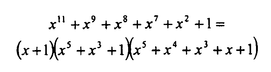
- This 11 bit CRC polynomial generates a (31,20) BCH code that has a minimum Hamming distance of 6. The codeword consists of the data to be protected and the CRC. In this application, this CRC protects exactly 20 bits of data (1 bit sync + 12 bits frame ID + 7 bits payload length = 20 bits). This polynomial was obtained from T. Wadayama, Average Distortion of Some Cyclic Codes, web site available at http://vega.c.oka-pu.jp/~wadayama/distortion.html, and its properties were verified using the techniques described in P. Koopman, "32-bit Cyclic Redundancy Codes for Internet Applications," Proceedings of the International Conference on Dependable Systems and Networks (DSN 2002), Washington DC, June 2002, pp. 459-468. The initialization vector of the register used to generate the header CRC shall be (1A)HEX.
- With respect to the computation of fHeaderCRC, the Sync Bit, the Frame ID and the Payload Length fields shall be fed into the CRC generator in network order, specifically the Sync Bit shall be shifted in first, followed by the most significant bit of the Frame ID field, followed by subsequent bits of the Frame ID, followed by the most significant bit of the Payload Length field, and followed by subsequent bits of the Payload Length field.
- The Header CRC field shall be transmitted such that the most significant bit of fHeaderCRC is transmitted first with the remaining bits of fHeaderCRC being transmitted in decreasing order of significance.
- A detailed description of how to generate or verify the Header CRC is given further on.
- The Cycle Counter field indicates the transmitting node's view of the cycle counter vCycle at the time of frame transmission.
- The Cycle Counter field shall be set to fCycleCount = vCycle before transmitting a frame.
- The Cycle Counter field shall be transmitted such that the most significant bit of fCycleCount is transmitted first with the remaining bits of fCycleCount being transmitted in decreasing order of significance.
- The FlexRay payload segment contains 0 to 254 bytes (0 to 127 two-byte-words) of data written by the host.
- Because of the limitations imposed on the representation of the length of the payload segment by the Payload Length field (fPayloadLength) of the header segment, the FlexRay Payload Segment shall consist of an even number of bytes. (The length of the payload segment indicated by fPayloadLength correlates with the number of bytes that are sent on the communication channel. It does not necessarily define the number of bytes used by the application in the payload section. The data provided by the application may be shorter than the payload section. A padding function in the communication controller fills the "missing" bytes if the configured transmit buffer is smaller than the configured payload length.)
- Note that the frame CRC described below has a Hamming distance of six for payload lengths up to 248 bytes. For payload lengths greater than 248 bytes the CRC only provides a Hamming distance of four.
- The first two bytes of the FlexRay payload segment may optionally be used as a message ID field, allowing receiving nodes to filter or steer data based on the contents of this field.
- The subsequent bytes of the payload segment may optionally be used as network management vector. The length of the network management vector is configured by gNetworkManagementVectorLength during CC_SoftReset and cannot be changed during the protocol startup phase (PSP) or during the protocol operation phase (POP). gNetworkManagementVectorLength can be configured between 0 and 12 bytes, inclusive. The network management indication bit in the frame header indicates whether the payload section contains the network management vector (Frames that contain network management data are not restricted to containing only network management data - the other bytes in the payload section may be used to convey additional, non-Network Management data.).
- If the optional message ID field is not used the network management vector (if present) starts with the first byte of the payload section.
- The individual bytes within the Payload Segment shall be transmitted such that the most significant bit of the byte is transmitted first with the remaining bits of the byte being transmitted in decreasing order of significance.
- The FlexRay trailer segment contains a single field, a 24-bit CRC for the frame.
- The Frame CRC field contains a Cyclic Redundancy Check code (CRC) computed over the Header and Payload segments of the frame. The computation includes all fields in these segments (This includes the header CRC, as well as any Communication Controller-generated "padding" bytes that may be included in the Payload segment.).
- The CRC is computed using the same generator polynomial on both channels. The CRC polynomial shall be

- This 24-bit CRC polynomial generates a code that has a minimum Hamming distance of 6 for codewords up to 2048 bits in length and a minimum Hamming distance of 4 for codewords up to 4094 bits in length. The codeword consists of all frame data and the CRC. This corresponds to H=6 protection for FlexRay frames with payload lengths up to 248 bytes and H=4 protection for longer payload lengths. This polynomial was obtained from G. Castagnoli, S. Bräuer, and M. Herrmann, "Optimization of Cyclic Redundancy-Check Codes with 24 and 32 Parity Bits, " IEEE Trans. Commun., vol. 41, pp. 883 - 892, June 1993., and its properties were verified using the techniques described in P. Koopman, "32-bit Cyclic Redundancy Codes for Internet Applications," Proceedings of the International Conference on Dependable Systems and Networks (DSN 2002), Washington DC, June 2002, pp. 459-468.
- The generation process of the CRC differs slightly depending on which channel the frame is being transmitted (Different initialization vectors are defined to prevent a node from communicating if it has crossed channels, connection of a single channel node to the wrong channel, or shorted channels (both controller channels connected to the same physical channel).):
- The initialization vector of the CRC generator shall be (FE DC BA)HEX for frames sent on channel A.
- The initialization vector of the CRC generator shall be (AB CD EF)HEX for frames sent on channel B.
- With respect to the computation of fFrameCRC, the frame fields shall be fed into the CRC generator in network order (that is, the first thing into the generator is the most significant bit of the Reserved Bit field, and the last thing into the generator is the least significant bit of the last byte of the Payload Segment).
- The Frame CRC field shall be transmitted such that the most significant bit of fFrameCRC is transmitted first with the remaining bits of fFrameCRC being transmitted in decreasing order of significance.
- A detailed description of how to generate or verify the Frame CRC is given further on.
- Under certain conditions a transmitting node may send a "null frame" which is a frame that contains no valid data in the payload segment. Such a frame is sent when a transmitter is configured to send in a given slot and channel of the static segment but is not in possession of valid data at the time when transmission of that slot is scheduled to begin. This could be caused by the host locking a transmit buffer and not releasing it before transmission time, or by a transmitter being configured for cycle counter filtering (see further on) and the current cycle counter does not match the filter. Additionally, a transmitting controller may indicate a null frame if the host has not successfully updated the data since the last scheduled transmission. This behavior is optional (see further on). The transmitter indicates a null frame by setting fNullFrameIndicationBit = 1.
- A Null Frame consists of
- A header segment as described above, which has fNullFrameIndicationBit = 1
- A payload segment with all bits set to zero
- A trailer segment as described above.
- Null frames shall only be sent in the static segment, hence the payload length is defined by gPayloadLengthStatic.
- The payload segment of a Null Frame shall be ignored by the receiver (The receiver uses the data in the Payload Segment for the Frame CRC checking process, but otherwise ignores the data.) but other fields of the frame may contain useful data (For example, the clock synchronization algorithm may make use of the arrival time of null frames with the Sync Bit field set to 1 (provided all other criteria for that frame's acceptance are met).).
- An overview of the byteflight frame format is given in Figure 35. The frame shall be transmitted on the network such that the header segment appears first, followed by the payload segment, and then followed by the trailer segment, which is transmitted last.
- The byteflight header segment consists of 2 bytes that contain several distinct fields; the Frame ID, a field of reserved bits, and the frame length. These fields are described in detail in the following sections.
- Within the header segment the fields shall be transmitted in the order indicated in Figure 35, moving from left to right (i.e., the Frame ID field is transmitted first and the Frame Length field is transmitted last).
- This field contains the Frame Identifier for the frame. Each frame that may be transmitted in a cluster has a frame ID fBfFrameID assigned.
- The frame ID fBfFrameID is a unique number per communication cycle and defines the minislot in which the frame is transmitted.
- Valid values for fBfFrameID range from (0000 0001)2 to (1111 1111)2.
- The Frame ID field shall be transmitted such that the most significant bit of fBfFrameID is transmitted first with the remaining bits of fBfFrameID being transmitted in decreasing order of significance.
- This field consists of four bits that may are used by the application.
- The fBfSpecialApplBits field shall be transmitted such that the most significant bit of fBfSpecialApplBits is transmitted first with the remaining bits of fBfSpecialApplBits being transmitted in decreasing order of significance.
- The fBfSpecialApplBits field in the transmitting node is written by the host (The four special application bits are written by the host of the transmitting node. The communication controllers on all nodes (transmitter and receiver) treat these bits as application data.).
- The Frame Length consists of a single parameter, fBfFrameLength, which indicates the number of data bytes that are contained in the payload segment of the frame.
- The frame length field does not include the number of bytes within the header and the trailer segment of the byteflight frame.
- The shortest possible length is 0 bytes (fBfFrameLength = (0000)2), the longest length is 12 bytes (fBfFrameLength = (1100)2). A frame which is received with fBfFrameLength greater than 12 shall be treated as an error.
- The Frame Length field shall be transmitted such that the most significant bit of fBfFrameLength is transmitted first with the remaining bits of fBfFrameLength being transmitted in decreasing order of significance.
- The byteflight payload segment consists of 0 to 12 bytes of data written by the host.
- The individual bytes within the Payload Segment shall be transmitted such that the most significant bit of the byte is transmitted first with the remaining bits of the byte being transmitted in decreasing order of significance.
- The byteflight trailer segment consists of 2 bytes that contain two distinct fields; a Frame CRC and the Frame Completion Bit. These fields are described in detail in the following sections.
- Within the trailer segment the fields shall be transmitted in the order indicated in Figure 35, moving from left to right (i.e., the Frame CRC field is transmitted first and the Frame Completion Bit is transmitted last).
- The Frame CRC field contains a Cyclic Redundancy Check code (CRC) computed over the Header and Payload segments of the frame. The computation includes all fields in these segments.
- The CRC generator polynomial shall be

- This is the same polynomial as used in the CAN protocol as defined in ISO/DIS 11898-1:1999, Road vehicles -- Controller area network (CAN) -- Part 1: Data Link Layer and Physical Signaling, International Standards Organization, 1999. It is optimized for code words of up to 127 bits.
- The initialization vector of the byteflight Frame CRC shall be (00)Hex.
- With respect to the computation of fBfFrameCRC, the frame fields shall be fed into the CRC generator in network order (that is, the first thing into the generator is the most significant bit of the Frame ID field, and the last thing into the generator is the least significant bit of the last byte of the Payload Segment).
- The Frame CRC field shall be transmitted such that the most significant bit of fBfFrameCRC is transmitted first with the remaining bits of fBfFrameCRC being transmitted in decreasing order of significance.
- A detailed description of how to generate or verify the Frame CRC is given below.
- The Frame Completion Bit, fBfFCB, is a single bit whose sole purpose is to allow the byteflight frame to end on a byte boundary.
- The Frame Completion Bit field shall be transmitted with fBfFCB = 0.
- The first two bytes of the payload segment of the FlexRay frame format can be used as receiver filterable data called Message ID.
- The Message ID is an application determinable number that describes the contents of the data segment.
- The Message ID is 16 bits long.
- At the transmitter the Message ID is written by the host as application data. The communication controller has no knowledge about the message ID and no mechanism inside the communication controller is based on the message ID.
- At the receiver the storage of a frame may depend on the result of a filtering process that makes use of the Message ID. All frame checks done in Frame Processing (see further on) are unmodified (i.e., are not a function of the Message ID). The use of the Message ID filter is defined in the Host Interface chapter (see further on).
- The optional use of Message IDs must be consistent in all frames in the whole cluster (Consistency means that a Message ID is used for ALL frames (both static and dynamic) in a cluster or it is not used for ANY frame. Partial use of the Message ID is not possible.).
- If this mechanism is used, the most significant bit of fMessageID shall be placed in the most significant bit of the first byte of the payload segment. Subsequent bits of fMessageID shall be placed in the next payload bits in order of decreasing significance.
- The Frame CRC calculation is done inside the communication controller before transmission or after reception of a frame. It is part of the frame transmission process or the frame reception process, respectively.
- The variable vCheckCRC_x denotes the result of the check of the consistency of a frame and its CRC for the respective communication channel. The calculation may be described by the following pseudocode.
- The values of the protocol constants cCrcSize, cCrcInit_x, and cCrcPolynomial depend on the frame format used, i.e. the FlexRay or byteflight frame format. For the FlexRay frame format the value of cCrcInit_x also depends on the channel that is used to transmit the frame:
FlexRay frame format / channel A:cCrcSize = 24; / / size of the register is 24 bits cCrcInit = (FE DC BA)HEX ; / / initialization vector of channel A cCrcPolynomial = (5D 6D CB)HEX ; / / hexadecimal representation of the CRC polynomial
FlexRay frame format / channel A:cCrcSize = 24; / / size of the register is 24 bits cCrcInit = (AB CD EF)HEX ; / / initialization vector of channel B cCrcPolynomial = (5D 6D CB)HEX ; / / hexadecimal representation of the CRC polynomial
byteflight frame format:cCrcSize = 15; / / size of the register is 15 bits cCrcInit = 0HEX ; / / initialization vector cCrcPolynomial = (45 99)HEX ; / / hexadecimal representation of the CRC polynomial - Short Description: Initialize the CRC shift register with the appropriate initialization value. As long as bits (vNextBit_x) from the header or payload segment of the frame are available the while-loop is executed. The number of bits available in the payload segment is derived from the payload length field. The bits (Transmitters use the bit sequence that will be fed into the coding algorithm, including any controller generated padding bits. Receivers use the decoded sequence as received from the decoding algorithm (i.e., after the removal of any coding sequences (e.g. Byte Start Sequences, Frame Start Sequences, etc.)).) of the header and payload segments are fed into the CRC register by using the variable vNextBit_x, bit by bit, in network order, e.g., for the FlexRay frame format the first bit used as vNextBit_x is the Reserved Bit field, and the last bit used is the least significant bit of the last byte of the Payload Segment.
-
• Req: Each product has to be optimized to meet the automotive and legal EMC requirements. External filters may not be required but may well be used.
Comment:
• Req: The power consumption during the normal operating mode and the low power mode has to be minimized.
Comment:
Typical values are given in the following table 1:
| Function | Min. | Typ. | Max. | Unit | Remarks |
| Quiescent current (from the permanent power) of the | 10 | µA | The bus driver monitors wake-up events, the voltage regulator is switched off | ||
| Current for the bus driver and the | 10 | mA | bus free - no actual communication | ||
| Current for the bus driver and the communication controller | 50 | mA | bus busy - communication active |
• Req: The voltage supply for the communication controller should be the same as for commercially available ECUs.
Comment:
• Req: All inputs and outputs of the bus driver and the communication controller which are directly coupled to the wire harness have to fit the known electric requirements. Support of future high supply voltages (36/42 V instead of 12 V) must be supported.
 // Initialize the CRC register
 vCrcReg_x(cCrcSize - 1 : 0) = cCrcInit_x;

 while(vNextBit_x)

       // determine if the CRC polynomial has to be applied by taking
      // the exclusive OR of the most significant bit of the CRC
      // register and the next bit to be fed into the register
      vCrcNext_x = vNextBit_x EXOR vCrcReg_x(cCrcSize - 1);

      // Shift the CRC register left by one bit
      vCrcReg_x (cCrcSize - 1 : 1) = vCrcReg_x(cCRCSize - 2 : 0);
      vCrcReg_x(O) = 0;

      // Apply the CRC polynomial if necessary
      if vCrcNext_x
         vCrcReg_x(cCrcSize - 1 : 0) = (vCrcReg_x(cCrcSize - 1 : 0)
         EXOR cCrcPolynomial;
      end;           // end if


 end;               // end while loop

FlexRay header CRC calculation:
| cHCrcSize = 11; | / / size of the register is 11 bits |
| cHCrcInit := (1A)HEX ; | / / initialization vector of Header CRC for both channels |
| cHCrcPolynomial := (3 85)HEX ; | / / hexadecimal representation of the Header CRC polynomial |
- vNextBit_x = vHNextBit_x;
- cCrcSize = cHCrcSize;
- cCrcInit = cHCrcInit;
- cCrcPolynomial = cHCrcPolynomial;

- 1. Beginning with the start of the reception the five frame header bytes are received without a coding error. The violation of this condition is considered to be a header-coding error (S_HeaderCodingError).
- 2. The header CRC verification according to the CRC calculation procedure returned with the result 'valid'. The violation of this condition is considered to be an invalid-header-CRC error (S_InvalidHeaderCRCError).
- 3. The remaining (2 * fPayloadLength + 3) bytes of the frame are received without a coding error using the fPayloadLength value extracted from the header of the frame. The violation of this condition is considered to be a frame-coding error (S_FrameCodingError).
- 4. The frame CRC verification according to the CRC calculation procedure returned with the result 'valid'. The violation of this condition is considered to be an invalid-frame-CRC error (S_InvalidFrameCRCError).
- 5. The frame end is reached without a coding error. The violation of this condition is considered to be a frame-coding error (S_FrameCodingError).
- 6. The node does not initiate an own transmission while reception is ongoing on the same channel. The violation of this condition is considered to be a transmission-conflict error (S_TransmissionConflictError).
| Transition Direction | Condition for Transition | Action taken on Transition | |
| from | to | ||
| FR_Idle | FR_Active | Transition of the channel state from channel idle to channel active | |
| FR_Active | FR_Idle | Transition of the channel state from channel active to channel idle. In this case a syntactically correct frame was received. | |
| FR_Active | FR_Abort | header-coding error detected | |
| OR invalid-header-CRC error detected | |||
| OR frame-coding error detected | |||
| OR invalid-frame-CRC error detected | |||
| FR_Abort | FR_Idle | Transition of the channel state from channel active to channel idle | |
| FR_Soft Reset | FR_Idle | Soft reset released | |
| AND channel is in the channel idle state | |||
| All states | FR_Soft Reset | Soft reset initiated | |
- 1. The frame ID included in the header of the frame is not larger than the number of the last static slot gNumberOfStaticSlots.
- 2. The sync bit is set.
- 3. The payload length included in the header of the frame is equal to the globally configured value of the payload length of a static frame held in gPayloadLengthStatic. The violation of this constraint is considered to be a payload-length-static error (S_PayloadLengthStaticError).
- 1. The payload length included in the header of the frame is equal to the globally configured value of the payload length of a static frame held in gPayloadLengthStatic. The violation of this constraint is considered to be a payload-length-static error (S_PayloadLengthStaticError).
- 2. The frame ID included in the header of the frame is equal to the value of the slot counter vSlotCounter[ch] both at the start of the frame as well as at the end of the frame. The violation of this constraint is considered to be a frame-ID error (S_FrameIDError). Figure 37 illustrates this constraint.
- 3. The cycle count included in the header of the frame is equal to the value of the cycle counter vCycle both at the start of the frame as well as at the end of the frame. The violation of this constraint is considered to be a cycle-count error (S_CycleCountError).
- 1. The frame ID included in the header of the frame is equal to the value of the slot counter vSlotCounter[ch] at the start of the frame. The violation of this constraint is called a frame-ID error (S_FrameIDError). Figure 38 illustrates this requirement.
- 2. The cycle count included in the header of the frame is equal to the value of the cycle counter vCycle both at the start of the frame as well as at the end of the frame. The violation of this constraint is considered to be a cycle-count error (S_CycleCountError).
- 3. The sync bit included in the header is set to '0'. The violation of this constraint is considered to be a sync-bit error (S_SyncBitError).
- Offset (phase) differences and
- Rate (frequency) differences
| Operation Mode: | FlexRay | byteflight | |
| Synchronization mode: | Multi-Master, distributed clock sync | Single-Master, with rate correction | Single-Master, without rate correction |
| Number of Sync Nodes: | [2 ... 16] | 1 | 1 |
| Number of Static Slots: | ≥ number of sync masters | ≥1 | 0 |
| Number of Sync Frames: | = number of | 1 | 0 |
| Number of Cold Starters | at least one | exactly one | exactly one |
- Single-master clock synchronization shall be performed if the static segment is configured with only one static slot (gNumberOfStaticSlots = 1).
- The node that owns the static slot must transmit sync frames in this slot in every cycle. This node is the only node in the cluster that transmits sync frames. It is the clock synchronization master and the remaining nodes are slaves.
- All other nodes shall receive the sync frames and perform the clock synchronization algorithm as if the node were in a cluster using distributed clock synchronization (see below).
- The behavior in case of a fault is described further on. The conditions to signal an fault are different for the master and for the salves and they are listed in Table 10 below.
- Distributed clock synchronization shall only be performed if the cluster is configured with a static segment (gNumberOfStaticSlots > 1).
- At least two nodes shall transmit sync frames.
- in the configuration (see Table 6),
- in the start-up (see further on) and
- signaling of a fault to the error management.
| Synchronization mode: | Multi-Master, distributed clock sync | Single-Master, with rate correction | |
| Missing Rate Correction Signal (MRCS) set to 1 | master | no sync frame pair in an even/odd double cycle | never |
| slave | no sync frame pair in an even/odd double cycle | ||
| Missing Offset Correction Signal (MOCS) set to 1 | master | no sync frame in odd cycle | never |
| slave | no sync frame in odd cycle | ||
| Clock Correction Limit Reached (CCLR) set to 1 | master | calculated offset or rate correction value outside the specified limits | never |
| slave | calculated offset or rate correction value outside the specified limits | ||
- Internally, nodes can time their behavior with microtick resolution. Microticks are time units derived from the (external) oscillator clock tick, optionally using a prescaler. Microticks are controller-specific units. They may have different durations in different controllers. The precision of a node's local time difference measurements is a microtick.
- Local controller time is based on cluster-wide synchronized cycle and macrotick values provided by the distributed clock synchronization mechanism. Finer resolution local timing shall be done using the node-specific microtick. The value vMacrotick.vMicrotick represents the controller local view of time within a given cycle.
- vCycle is the (controller-local) cycle number and is increased once every communication round. At any given time all nodes should have the same value for vCycle (except due to imperfect synchronization at cycle boundaries).
- Cycle counter values (vCycle) range from zero (00 0000)2 to cCycleMax (11 1111)2.
- When cCycleMax is reached, the cycle counter vCycle shall be reset to zero (00 0000)2 in the next communication cycle (see Procedure 3)
- vMacrotick is the current value of the (controller-local) macrotick counter.
- gMacroPerCycle defines the (integer) number of macroticks per cycle (see Figure 39).
- Within tolerances, the duration of a macrotick is constant throughout the cluster on synchronized nodes.
- Every node in the cluster has its own local view of the global time. The local view of global time is represented by a vector consisting of the current cycle number (vCycle) and the current macrotick value (vMacrotick). The value vCycle.vMacrotick is the (controller-local) view of the global time in the cluster. It is visible to the application.
- pMicroPerMacroNom is the (controller-specific) nominal number of microticks per macrotick.
- vRateCorrection is the (integer) number of microticks that shall be added to the pMicroPerMacroNom * gMacroPerCycle microticks in the current cycle to produce the correct cycle length. vRateCorrection may be negative. The value of vRateCorrection is determined by the clock synchronization algorithm. It may only change once (usually at the beginning) per cycle.
- pMicroOverheadPerCycleNom is the initial configuration value of vRateCorrection.
- The duration of the current controller-local macrotick is an integer multiple of controller-local microticks and is represented by vMicroPerMacroCorr. The value of vMicroPerMacroCorr within one controller may change from macrotick to macrotick.
- In any given cycle, vRateCorrection microticks shall be distributed across the gMacroPerCycle macroticks comprising the cycle in order to adjust the cycle length to the proper duration. Consequently, vMicroPerMacroCorr does not remain constant. In general, vRateCorrection is nonzero and is not a multiple of gMacroPerCycle. Consequently, the process of distributing the vRateCorrection microticks across the gMacroPerCycle macroticks conceptually introduces fractional macroticks.
- At the beginning of the first communication cycle the "local time variables" shall be initialized (see Procedure 2).

- The initialization of the first three values differs if the node reintegrates into a running cluster (see Chapter "Wakeup, Startup and Reintegration").


- The host shall be able to read the cycle counter and the macrotick counter. The update of the cycle counter shall be atomic with the macrotick counter. An atomic action is an action where no interruptions is possible.
- The duration of a Macrotick shall be an integer number of a Microticks, however, the number of microticks per macrotick may differ from macrotick to macrotick. Before the first correction value is calculated the clock synchronization algorithm shall work with nominal macroticks, using vMicroPerMacroCorr = pMicroPerMacroNom + pMicroOverhea dPerCycleNom (see Procedure 4).
- The number of microticks per nominal macrotick may differ between nodes and depends on the oscillator frequency and the prescaler.
- The duration of one cycle shall be an integer number of a macroticks. The number of macroticks per cycle is intended to be identical in all nodes in a cluster (see Figure 39).


- For a given cycle (without offset correction) the average length of a macrotick is given by pMicroPerMacroNom + vRateCorrection / gMacroPerCycle.


- Offset correction has an additional influence. Therefore there is a difference between the variables vMicroPerMacroCorr and vMicroPerMacroRateCorr.
- Since there is no real division available in hardware, the implementation will not precisely replicate the above procedure. Most likely the variable vMicroPerMacroCorr will not be explicitly calculated in hardware.
- As is typically true with pseudocode, the above procedure provides insight into the behavior of the mechanism, but not its implementation.
- The node (or nodes in the case of a startup with collisions) that transmits the first CAS during startup, shall initialize the cycle counter and the cycle time to zero at the beginning of the communication cycle following the transmission of the CAS. See above for details.
- The duration of a static slot gdSlot, a communication cycle gdCycle, and the idle time at the end of a communication cycle gdNetworkIdle shall be all expressed as an integer number of macroticks.
- Each node with pChannels == gChannels that is configured to send in the static segment of the communication cycle may send at most one frame per communication cycle with the sync bit set.
- The sync bit may only be set in frames that are transmitted on all channels (gChannels - one or two channel configuration).
- Not all nodes that are configured to send in the static segment of the communication cycle need to send frames with the sync field set.
- The communication controller shall count all correctly received frames where the sync bit is set. The counter is reset at the start of the communication cycle. This number of the correct received sync frames of the previous communication cycle is presented by vValidSyncFrameCount and shall be accessible to the host.
- If a controller receives more than gSyncNodeMax the first gSyncNodeMax shall be used for clock synchronization.
- The calculation of the correction values shall take place every second communication cycle during the network idle time (NIT).
- The expected arrival time of a frame is the Minislot action point of the corresponding slot. It is represented by vExpectedArrivalTime = vMacrotickExpected.vMicrotickExpected, where vMacrotickExpected and vMicrotickExpected are the macrotick and microtick timer values at the instant of the minislot action point.
- The observed arrival time of a frame is the instant of reception of the 1/0-edge in the middle of the first Byte Start Sequence after the Frame Start Sequence. It is represented by vObservedArrivalTimeChx = vMacrotickObserved.vMicrotickObserved, where vMacrotickObserved and vMicrotickObserved are the macrotick and microtick timer values at the instant of reception of this edge.
- The time difference between expected and observed arrival time is calculated as follow:
- vMeasureChx = vObservedArrivalTimeChx - vExpectedArrivalTime - gdFrameStartSequence - 1 gdBit - pDelayCompensationChx
- The global parameters gdFrameStartSequence and gdBit are specified in units of bit times that can differ between nodes if clock sources with different frequencies are used. Internally these parameters are represented in microticks.
- The sync frame validity checks used during startup and reintegration and during normal operation are described in Section "Frame Processing".
- The time difference measurement shall be done for all channels pChannels.
- If there are time difference measurements from more than one channel for a given sync frame, the smallest value shall be taken.
- If only one valid frame is received within a given static slot, this single observation shall be used for the Time Difference Measurement.
- Every node has to be able to store measurement values with their associated Frame IDs for gSyncNodeMax sync nodes. A counter vValidSyncFrameCount is increased when a valid sync frame is received. If a node receives more than gSyncNodeMax sync frames in one communication cycle it is communication to the Error Management but uses the first gSyncNodeMax observations for the calculation of the rate and drift correct values. The counter vValidSyncFrameCount is set to zero when a new communication cycle starts.
- Note, the Frame Identifiers of sync frames expected to be received are not stored in the configuration of a node.
- Individual delay compensation values pDelayCompensationChA and pDelayCompensationChB can be configured for each channel. The compensation values should be set to the minimum propagation delay time experienced by any node in the cluster.
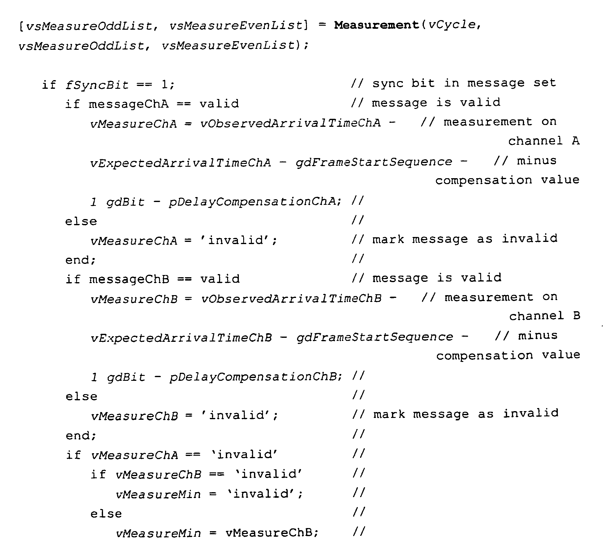

1. The measured values are sorted and the n largest and the n smallest values are discarded.
7. The value of n is adapted dynamically to the number of values in the sorted list.
| Number of Values | n |
| 1 - 2 | 0 |
| 3 - 7 | 1 |
| 8 - 16 | 2 |
8. The largest and the smallest of the remaining values are averaged for the calculation of the midpoint value. The resulting value is assumed to represent the node's deviation from the global time base and serves as the correction term (see Figure 43).

- If the list contains only one value this value is used for clock synchronization.
- 1. The Offset Correction Value vOffsetCorrection is a (signed) integer indicating by how many microticks the node should shift its start of the cycle.
- 2. Offset calculation shall be finished before start of cycle, and it may only start after end of last synchronization slot.
- 3. The node's own offset value (most likely zero, depending on the measurement principle used) shall be included if it transmits a sync Frame.
- 4. The calculation of the offset correction value shall be done every communication cycle, but the offset correction shall be only done in the odd numbered cycles. In even numbered cycles no offset correction shall be done.
- 5. The calculated offset correction value shall be checked against the limit values every cycle. If the calculated offset correction value outside of the allowed range a warning shall be raised to the host (further behavior is specified in the following text).
- 6. If the node transmits sync frames, its own offset time shall be included by adding one instance of the value zero (depending on measurement method) to the list of measured time difference values from the last cycle.
- 7. The offset correction value shall be determined by applying the FTA/FTM to the list of measured time differences.


- 1. The calculation of the rate correction value shall be done after every second communication cycle, in the odd numbered cycles (see Figure 44).
- 2. The rate correction value shall be determined by comparing the corresponding measured time differences from two successive cycles. Specifically, a new list of values shall be created whose elements are calculated by taking the differences between the most recent cycle's measured time difference and the previous cycle's measured time difference. Only time values corresponding to frames passing the validity checks on both channels shall be used.
- 3. If the node transmits sync frames its own rate correction influence shall be considered by adding an instance of the value zero to the list of calculated time difference.
- 4. In the next step the FTA/FTM algorithm described above shall be applied to the list of time difference values built in the previous two steps.
- 5. After calculating the correction term, the stored measurement values shall be deleted so that the next calculation starts with a new set of values.
- 6. The ideal new rate correction value is the sum of the value calculated in the previous step and the current correction value.
- 7. To prevent cluster drift that can result from an accumulation of rounding errors the rate correction term actually used is not the ideal rate correction, but a slight modification of this term towards the configuration value. The modification term is a positive integer pClusterDriftDamping that is part of node's static configuration.


- pClusterDriftDamping should be configured in a way that the damping value in all controllers has nearly the same duration. A configuration value is used to adapt in case of different Microtick duration in different controllers.
- After calculation of the rate correction value the memory for the measurement values is cleared and marked empty. It should be clear that the offset correction value is calculated before the memory is cleared.
- External offset correction shall be performed in the same cycle in all nodes of a cluster; external rate correction shall be performed in the same double cycle in all nodes of a cluster.
- The external correction terms (offset and rate correction terms) available to the communication controller when the network idle time starts are the values that are used. If no values are available the external correction values shall be set to zero for the next double cycle.
- The external correction terms shall be checked against limits and applied following the corresponding tasks are performed for the internal correction terms. This shall take place during the Network Idle Time.
- Following the Network Idle Time, an aggregate rate correction term consisting of correction components from the internal and external rate correction terms, shall be applied during the next two communication cycles.
- The aggregate offset correction term, consisting of correction components from the internal and external offset correction terms, shall be applied in the remainder of the Network Idle Time, before the next cycle starts.
- In soft reset, the initial external rate correction may be accomplished by setting the external rate correction term by the host.
- The correction values are in the green region if:

- If both correction values are in the green area the correction is done.
- -gRateCorrectionOut is the lower boundary and +gRateCorrectionOut is the upper boundary of the green area for the rate correction.
- -gOffsetCorrectionOut is the lower boundary and +gOffsetCorrectionOut is the upper boundary of the green area for the offset correction.
- The correction value is in the red region if

- The significance of having correction values in the red region depends on whether the node is in the process of startup, or not. During normal operation this is to be considered a fault condition. If vRateCorrection OR vRateCorrection + vRateCorrectionExtern is outside the specified area the error signal CCLR is set to 1. If vOffsetCorrection OR vOffsetCorrection + vOffsetCorrectionExtern is outside the specified area the error signal CCLR is set to 1, too. During startup and reintegration this condition is treated differently (see further on in the text).
- The values of gRateCorrectionOut and the gOffsetCorrectionOut are identically specified for all nodes in the cluster. They are defined in terms of macroticks or fractions of a macrotick. From these cluster-wide values the configuration data for each node shall be calculated (measured in microticks). These values shall be included in the configuration interface. These calculations are summarized as follows:

- Rate correction shall be accomplished by modifying the value of vRateCorrection (see Procedure 9), which shall be subsequently distributed over the macroticks comprising the next cycle.
- Offset correction shall be accomplished by modifying the value of vOffsetCorrection (see Procedure 8), which shall be subsequently distributed over the macroticks comprising the current Network Idle Time.
- The rate correction term shall be uniformly distributed over the entire cycle (see Figure 44).

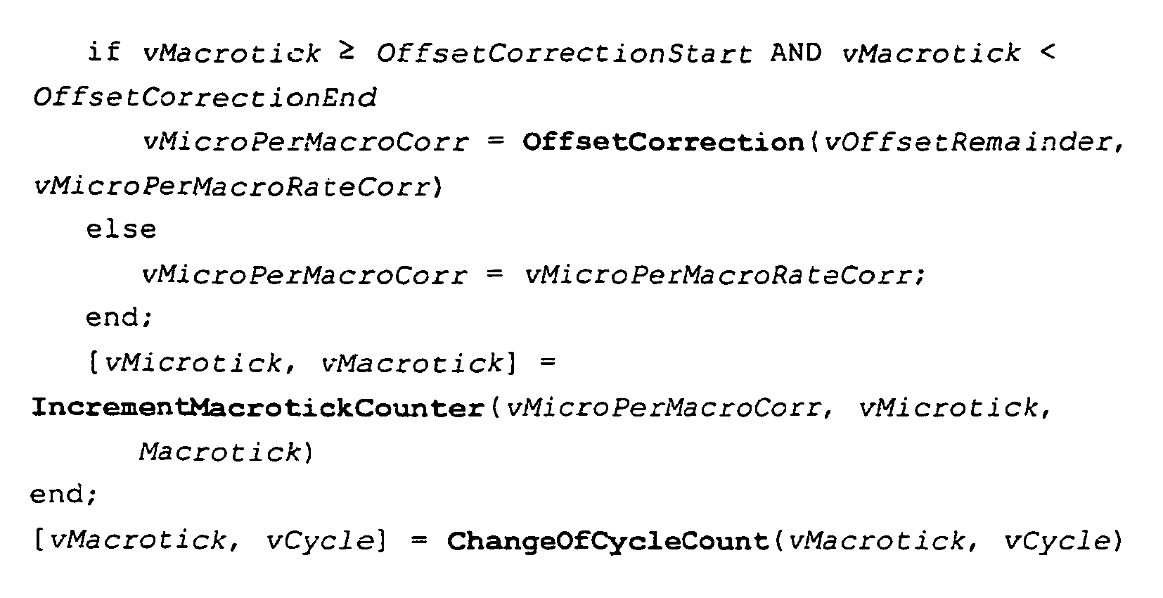
- This is only an example.
- As previously mentioned, it seems to be unlikely that the variable vMicroPerMacroRateCorr can be calculated explicitly in hardware. It is more likely that the IncrementMacrotickCounter procedure will be an intrinsic part of at least the rate part of the microtick distribution state machine.
- Offset correction shall be done during the network idle time by increasing or decreasing the size of macroticks depending on the value of vOffsetCorrection.
- It is not required that all controllers perform their offset correction identically. However, they shall perform the offset correction in the Network Idle Time. The offset correction should be completed at least one macrotick before the end of the NIT and therefore before the communication cycle ends.
- The offset correction term, vOffsetCorrection, is a signed integer that shall be visible to the application. The maximum number of microticks by that a macrotick can be increased (due to offset correction and rate correction combined) shall be bounded by a configuration constant pMicroPerMacroMax. The offset correction term, vOffsetCorrection, shall be distributed across the first, and subsequent macroticks to the limit allowed by pMicroPerMacroMax, until the total offset term is distributed.
- The maximum number of microticks by that a macrotick can be decreased (due to offset correction and rate correction combined) shall be bounded by a configuration constant pMicroPerMacroMin. The offset correction term, vOffsetCorrection, shall be distributed across the first, and subsequent macroticks to the limit allowed by pMicroPerMacroMin, until the total offset term is distributed.
- pMicroPerMacroMax is the maximum length of a macrotick in microticks.
- pMicroPerMacroMin is the minimum length of a macrotick in microticks.

| Name | Description | Range / Value | Units | |
| vDeltaCorrect | Additional microticks per macrotick necessary as a result of clock rate correction | µT | ||
| vIntegerRatio | The integer portion of the corrected microtick to macrotick ratio vRatioMicroMacro. | - | ||
| vMicroOverheadPerCycle | The integral number of microticks that must be added to (or subtracted from, if negative) the current cycle in order for the cycle to have the correct length. | µT | ||
| vMicroPerMacroRate Corr | µT | |||
| vOffsetRemainder | ||||
| vRatioMicroMacro | Floating-point number representing the ratio of the number of microticks to the number of macroticks per cycle. vRatioMicroMacro = vIntegerRatio + vRest | - | ||
| vRemainingSumOfFractionalParts | Floating-point number used for clock rate correction that indicates the total fractional microticks that have not yet been corrected by the insertion or deletion of a microtick from a macrotick. When the absolute value exceeds 1 a microtick is added or removed. | µT | ||
| vRest | Floating-point number indicating the fractional portion of vRatioMicroMacro. | - |
When the listen phase is over, the communication controller waits for at least one channel to become idle. This reduces the risk of interrupting communication that is just received. It cannot be required that both channels in a two-channel system be idle since then a faulty, noisy channel could prevent the system wakeup. Most symbols and frames, especially during the startup phase where communication is more sparse and thereby more easily overlooked than during later phases, occur on both channels at the same time. E.g. the CAS symbol is transmitted simultaneously on both channels. Requiring at least one channel to be idle prevents the wakeup from beginning to transmit while such a symbol is received on both channels but before it is recognized. The communication controller allows only a predefined number of attempts to transmit the wakeup pattern. If this number is exceeded, the wakeup process is aborted.
The sync nodes that are allowed to start up the cluster wait for their listen time-out to expire. A received frame (S_SuccessfulHeaderReception) or CAS symbol (S_CASReception) prolongs the time-out. When the time-out expires, the node enters the coldstart path. In case no activity at all is detected, a special timeout expires and thereby enables a fast startup.
| State Transition | Transition Direction | Condition for Transition | Actions taken on Transition | ||
| from | to | ||||
| G1 | CC_Soft Reset | CC_Wake Up Listen | soft reset released (in the respective control register) | vWakeupCount, vdWakeup and vdWakeupNoise are set to zero. | |
| AND | wakeup mode configured | ||||
| The wakeup status vector is cleared (vWakeupFrameHead erReceived, vWakeupSymbolRece ived, vWakeupFailed and vWakeupComplete). | |||||
| G2 | CC_Startup Listen | soft reset released (in the respective control register) | vdStartup, vdStartupNoise and | ||
| AND | static, mixed or dynamic mode configured (gNumberofStaticSlots greater than or equal one) (A minimum of at least two static slots is required for a static or mixed configuration in FlexRay mode; only one static slot is configured in dynamic mode.) | and vColdStartCount are set to zero. The startup status vector is cleared (vCCMS, vSMMS, vOpViaColdstart, vColdstartAborted and vColdstartNoise) Error flags vMRCS and vCCLR are cleared | |||
| G3 | CC_byte flight Listen | soft reset released (in the respective control register) | |||
| AND | byteflight mode configured | ||||
| AND | slave role configured (pMaster not set) | ||||
| G4 | CC_Send Symbol | soft reset released (in the respective control register) | |||
| AND | byteflight mode configured | ||||
| AND | master role configured (pMaster set) | ||||
| G5 | describe further on | ||||
| G6 | describe further on | ||||
- CC_SoftReset
- CC_WakeupListen
- CC_WakeupSend
| State Transition | Transition Direction | Condition for Transition | Action taken on Transition | |
| from | to | |||
| W1 | CC_Wakeup Listen | CC_Soft Reset |  | Set the flag corresponding to the exit condition (refer to the wakeup status vector described further on). |
 | ||||
| W2 | CC_Wake up Send |  | Increase vWakeupCount by one. | |
| W3 | CC_Wakeup Listen | CC_Wake up Listen | Reception of channel activity on either channel. | vdWakeup is reset to zero. |
| W4 | CC_Wake up Listen | Reception of a valid CAS symbol on either channel (S_CASReception occurred) | vdWakeupListen is reset to zero. | |
| W5 | CC_Wakeup Send | CC_Soft Reset | Transmission of Tx-wakeup pattern completed. | vWakeupComplet e is set in the startup status vector |
| W6 | CC_Wake up Listen | Continuous 'active low' of more than gdWakeupMaxCollision detected during an idle phase of the Tx-wakeup pattern (S_CheckWakeupCollision occurred). | vdWakeup and vdWakeupListen are reset to zero. | |
- Abort because the communication controller has received a frame header without coding violation, which is signaled by setting the vWakeupFrameHeaderReceived flag (W1).
- Abort because the communication controller has received a valid Rx-wakeup symbol on channel vWakeupChannel, which is signaled by setting the vWakeupSymbolReceived flag (W1).
- Abort due to too many wakeup attempts, which is signaled by setting the vWakeupFailed flag (W1).
- The complete transmission of the Tx-wakeup pattern, which is signaled by setting the vWakeupComplete flag (W5).
The counter vWakeupCount is set to zero upon transition G1 from the CC_SoftReset to the CC_WakeupListen state.
Two timers are defined:
- vdWakeup
- vdWakeupNoise
-
Node 1 is awake. It has decided to wake up the cluster.Node 2 andNode 3 are in a power-saving sleep mode. - The Host of Node 1 (Host 1) checks for wakeup activity by checking if one of its bus drivers has received an Rx-wakeup symbol. Since neither of them has,
Host 1 must wake both channels. -
Host 1 commandsBG 1B (the bus guardian ofNode 1 and channel B) to enter its wakeup mode. -
Host 1 commands CC 1 (the communication controller of Node 1) to wake up channel B by setting vWakeupChannel to channel B and setting/clearing the needed bits in the CC-Host interface (for a more detailed description, see further on in the description). -
CC 1 enters the CC_WakeupListen state. It does not receive any activity on either channel. So the timer vdWakeup expires. TheCC 1 enters the CC_WakeupSend state. - During the CC_WakeupSend state, the Tx-wakeup pattern is transmitted on channel B. During the idle phases of the Tx-wakeup pattern,
CC 1 detects no activity on channel B. After complete transmission, theCC 1 sets vWakeupComplete and reenters CC_SoftReset. -
Host 1 commandsBG 1B to leave its wakeup mode. - The wakeup pattern has triggered the wakeup receiver of the bus driver of Node 2 (which is connected only to channel B).
Node 2 initializes. -
Host 1 has meanwhile read the wakeup status vector ofCC 1 and continues waking the other channel. -
Host 1 commandsBG 1A to enter its wakeup mode. -
Host 1 sets vWakeupChannel to channel A and commandsCC 1 to execute the wakeup mode. -
CC 1 again enters the CC_WakeupListen state. It does not receive any activity on either channel. So the timer vdWakeup expires. TheCC 1 enters the CC_WakeupSend state. - During the CC_WakeupSend state, the Tx-wakeup pattern is transmitted on channel A. During the idle phases of the Tx-wakeup pattern,
CC 1 detects no activity on channel A. After the complete transmission, theCC 1 sets vWakeupComplete and reenters CC_SoftReset. - Host A commands
BG 1A to leave its wakeup mode. - The wakeup pattern has triggered the wakeup receiver of the bus driver of Node 3 (which is connected only to channel A).
Node 3 initializes. - Host A reads out the wakeup status vector of
CC 1 and decides to continue with the startup, since both channels have been awakened. It sets the vColdStartlnhibit flag and commandsCC 1 to enter the CC_StartupListen state. - After some time,
Node 2 andNode 3 are completely configured. Neither are sync nodes and each is only connected to one of two channels. Additionally, their bus drivers signal that they have received Rx-wakeup patterns, so their Hosts must not perform a wakeup of their own. Instead, both Hosts command their communication controllers to begin Startup. BothCC 2 andCC 3 remain in the CC_StartupListen state. - Finally
Node 1 decides that enough time has passed to allow the other Nodes in the cluster to wake up and configure themselves. It clears the vColdStartInhibit flag of its communication controller and allows it thereby to enter the CC_ColdStartICW state.
-
Node 1 is awake. It has decided to wake up the cluster.Node 2 andNode 3 are in a power-saving sleep mode. - The Host of Node 1 (Host 1) checks for wakeup activity by checking if its bus driver has received an Rx-wakeup symbol. Since it has not,
Host 1 decides to wake its channel. Since this node is not a sync node, the Host does not have to wake its channel before entering the startup. In this example, the application demands it anyway. -
Host 1 commandsBG 1B (the bus guardian ofNode 1 and channel B) to enter its wakeup mode. -
Host 1 commands CC 1 (the communication controller of Node 1) to wake up channel B by setting vWakeupChannel to channel B and setting/clearing the needed bits in the CC-Host interface (for a more detailed description, see the following description). -
CC 1 enters the CC_WakeupListen state. It does not receive any activity on its channel. So the timer vdWakeup expires. TheCC 1 enters the CC_WakeupSend state. - During the CC_WakeupSend state, the Tx-wakeup pattern is transmitted on channel B. During the idle phases of the Tx-wakeup pattern,
CC 1 detects no activity on channel B. After complete transmission, theCC 1 signals this by setting the vWakeupComplete flag and reenters the CC_SoftReset state. -
Host 1 commandsBG 1B to leave its wakeup mode. - The wakeup pattern has triggered the wakeup receiver of the bus driver of Node 2 (which is connected to both channels).
Node 2 initializes. -
Host 1 reads the wakeup status vector ofCC 1. It notices thatCC 1 completed the transmission and commandsCC 1 to enter the CC_StartupListen state.Node 1 is not a sync Node and has now to wait for some other Node to initialize startup. - Meanwhile,
Node 2 has awakened.Node 2 is a sync Node and is allowed to perform a coldstart, so it must perform a wakeup before entering startup. -
Host 2 checks for wakeup activity by evaluating if one of its bus drivers has received an Rx-wakeup symbol. It notes that the bus driver of channel B has received an Rx-wakeup symbol and so only has to wake channel A. -
Host 2 commandsBG 2A to enter its wakeup mode. -
Host 2 sets vWakeupChannel to channel A and commandsCC 2 to execute the wakeup process. -
CC 2 enters the CC_WakeupListen state. It does not receive any activity on either channel. So the timer vdWakeup expires. TheCC 2 enters the CC_WakeupSend state. - During the CC_WakeupSend state, the Tx-wakeup pattern is transmitted on channel A. During the idle phases of the Tx-wakeup pattern,
CC 2 detects no activity on channel A. After the complete transmission, theCC 2 signals this by setting the vWakeupComplete flag and reenters the CC SoftReset state. -
Host 2 commandsBG 2A to leave its wakeup mode. - The wakeup pattern has triggered the wakeup receiver of the bus driver of Node 3 (which is connected only to channel A).
Node 3 initializes. -
Host 2 reads out the wakeup status vector ofCC 2 and decides to continue with the startup. Since some other Node had already awakened channel B,Host 2 assumes that other Nodes are already awake and initialized. It clears the vColdStartlnhibit flag and commandsCC 2 to enter the CC_StartupListen state.
The cluster wake-up must precede the communication startup in order to ensure that all mechanisms defined for the startup work properly. After initial wake-up the whole network behaves like a broadcast medium.

- 1. If communication channel activity (Any signal edge detectable at the receiver (i.e., a signal edge, which has passed the glitch filter) is referred to as "channel activity" (channel state machine has entered the active state).) is detected on one of the configured pChannels channels while the node is in the CC_StartupListen state, the listen-timeout vdStartup shall be reset.
- 2. As long as the channel status of one of the configured pChannels channels is active the timer is continuously reset. The timer shall resume counting once the channel idle state is reached for all pChannels channels and the node is still in the CC_StartupListen state.
- 1. The transition from channel idle to channel active shall not influence the timer. The node has to receive a certain pattern (s. below) in order to reset the timer vdStartupNoise.
- 2. If S_SuccessfulHeaderReception or S_CASReception occur for any channel while the node is in the CC_StartupListen state, the listen-timeout vdStartupNoise shall be reset.


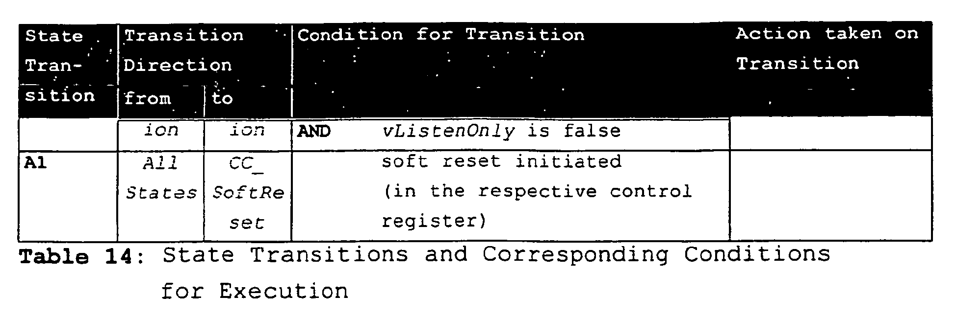
- A node entering CC_StartupListen shall reset and start a timer with the timeout value vdCycleWithHistory, if vRefSync is nonzero. This timer shall encompass the same time period gdStartup as the vdStartup timeout.
- The timeout vdCycleWithHistory shall not be reset due to channel activity in the CC_StartupListen state
- Upon the expiration of timeout vdCycleWithHistory, vRefSync shall be cleared. This setting (vRefSync=0) prevents the restart of vdCycleWithHistory
- The node shall only enter integration path (via the CC_InitSync state), if the fFrameID of a received S_ValidEvenStartupFrame is not equal to the ID stored in vRefSync. Since there is only one sync node available in TT-M mode, it is counterproductive to attempt to sync to a different node.
- It has to be ensured that a single sync node is going to start the communication cluster. Therefore, other sync nodes have to be prevented from entering the coldstart path. When multiple nodes enter simultaneously the CC_ColdStartICW state, a resolution mechanism ensures that all but one return to CC_StartupListen state.
- In the CC_ColdStartICW state the coldstart initiating node is expected to have exclusive access to the channels in the fault-free case. Other nodes that are integrating based on the sync frame reception of the coldstart initiator always follow a defined procedure that ensures that for initial cycles in the integration path these nodes stay passive. Consequently, the node initiating the coldstart should not receive any responses while in the CC_ColdStartICW state. Therefore, any frame reception during the CC_ColdStartICW state is due to another node having entered coldstart path at the same time (refer to bullet above) or to an error scenario.
- With the transition into the CC_ColdStartICW state the variable vColdStartCount shall be incremented by one.
- With each new cycle-start in the CC_ColdStartICW state, vColdStartCount shall be incremented by one.
- At the end of each cycle, vColdStartCount is compared to the allowed maximum gColdStartMax. If vColdStartCount is equal to gColdStartMax, the node shall re-enter the CC_StartupListen state. In this case, the node that initiates the coldstart has not been able to achieve communication with another node (transition to CC_NormalOperation state) within gColdStartMax cycles.
- Once this condition had become true, the sync node shall not be able to enter the coldstart path again. Only the host can reset this status (by forcing the transition to the CC_SoftReset state).
- shall remain in the CC_ColdStartVCW state, if no response has been received at all (and vColdStartCount is smaller than gColdStartMax),
- shall step back to the CC_StartupListen state, if the response does not fit to the node-local communication schedule,
- shall enter normal operation (the CC_NormalOperation state), if the response is in accordance with the node-local communication schedule.
- First, received sync frames must be in accordance to the node-local communication schedule
- Furthermore, the correction terms of the clock synchronization must not exceed the configured boundaries.

- vValidSyncCount[ch] = 1;
- vInvalidSyncCount[ch] = 0;
- |vOffsetCorrection| ≤ pOffsetCorrectionOut
- |vRateCorrection| ≤ pRateCorrectionOut
- S_ValidOddStartupFrame is received too early on one of the channels ch, for which an S_ValidEvenStartupFrame has already been received
- no S_ValidOddStartupFrame is received within a defined period on any of the channels ch for which an S_ValidEvenStartupFrame has already been received
- vValidSyncCount(ch) = 0;
- vInvalidSyncCount[ch] = 0;

- For sync nodes that do not operate in listen-only mode (vListenOnly is false) vSyncPairs needs to be at least one, otherwise no integration shall be possible. In that case, the node shall re-enter the CC_StartupListen state. This characterizes the scenario, where the original reference node does not maintain proper sync frame transmission for the entire integration phase.
- This holds also for nodes in TT-M mode, which are going to integrate to the 'master'-driven schedule. The parameter vSyncPairs needs to be at least one; otherwise no integration shall be possible. In that case, the node shall re-enter the CC_StartupListen state.
- If a sync node is configured as a listen-only node (vListenOnly is true), it has to fulfill the same condition as non-sync nodes in TT-D protocol mode. These nodes need to receive at least two matching pairs of sync frames suitable for rate measurement (same frame identifier, consecutive occurrence). Only if there is already a communication established comprising at least two sync nodes (nodes in the CC_NormalOperation state) can non-sync nodes (or sync nodes in listen-only mode) join in. For these nodes vSyncPairs needs to be at least two, otherwise no integration shall be possible. The node shall re-enter the CC_StartupListen state, if vSyncPairs is zero.
- |vOffsetCorrection| ≤ pOffsetCorrectionOut
- |vRateCorrection| ≤ pRateCorrectionOut.

- A correctly configured sync master communication controller (pMaster is true) shall enter the startup sequence via the transition from CC_SoftReset to CC_byteflightMaster.
- A single node should be configured as the sync master node, which must send a status symbol on all gChannels channels. For the sync master node pChannels must be equal to gChannels.
- A correctly configured slave node communication controller (pMaster is false) shall enter the startup sequence via the transition from CC_SoftReset to CC_byteflightListen.
- All slave nodes shall synchronize to the status symbol transmitted by the sync master node. If that node does not start, the system does not start up.
- Slave nodes start their communication cycle on both channels with the reception of the first valid status symbol on one of the pChannels channels.
| State Transition | State Direction | Condition for Transition | Action taken on Transition | ||
| from | to | ||||
| B1 | CC_byte flight Listen | CC_byte flight Slave | reception of a valid status symbol at one of pChannels channels | ||
| AND | vListenOnly is false | ||||
| B2 | CC_byte flight Passive | reception of a valid status symbol at one of pChannels channels | |||
| AND | vListenOnly is true ('Listen-only' mode is an invalid configuration for the master node!) | ||||
| B3 | CC_byte flight Slave | CC_byte flight Listen | network idle time reached (vMacrotick== gdCycle-gdNIT; based on local timers) | ||
| B4 | CC_Send Symbol | CC_byte flight Master | transmission of the status symbol finished | ||
| B5 | CC_byte flight Master | CC_Send Symbol | end of current cycle (derived from local cycle time) | ||
| B6 | CC_byte flight Passive | CC_byte flight Listen | network idle time reached (vMacrotick== gdCycle-gdNIT; based on local timers) | ||
| A1 | All States | CC_Soft Reset | soft reset initiated (in the respective control register) | ||
- State transitions with prefix 'V' corresponding to certain voltage levels
- State transitions with prefix 'L' indicate states transitions corresponding to logical conditions
The remainder of this chapter consists of sections corresponding to each of the FlexRay hardware components. Each of these sections consists of two subsections; a descriptive overview of the component's states followed by a more formal behavioral description in the form of a state diagram accompanied by a table detailing the transitions in the diagram.
- In general three different voltage levels and corresponding HW states have to be distinguished:
- PowerOff - The supply voltage is not available or is below a pre-defined level. Consequently, some integrated circuits are not able to keep their pins in a defined state, e.g. tri-state. The semiconductor manufacturer has to guarantee that during power up/power down no disturbances occur or has to specify the affected pins and their behavior.
- PowerOn - The supply voltage level is high enough to guarantee a defined state of the pins, where no disturbances occur.
- Operating/Normal - The supply voltage level allows full operation (note: Operating/Normal is a substate of PowerOn).
- The voltage is below a pre-defined threshold for proper operation
- Halt of all CC internal clocks
- The CC must not drive any pins
- The voltage level is above a threshold to guarantee a defined state of the pins
- All controller clocks halt immediately
- The CC must not drive any pins
- The CC supports regular communication function
- Immediately halt all CC internal clocks except those that are needed for operating the host interface.
- Regular communication shall be supported
- When this state is present communication is inactive
- The power consumption of the electrical CC is significantly reduced compared to CC_Normal
- All CC clocks off except those that are needed for wakeup detection
- Configuration data will remain unchanged
| State Transition | Transition Direction | Conditions for Transition | Action taken on Transition | ||
| From State | To State | ||||
| V1 | CC_PowerOff | CC_PowerOn | CC supply voltage rises above CC_U1 | ||
| V2 | CC_PowerOn | CC_PowerOff | CC supply voltage drops below CC_U2 | ||
| L1 | CC_HWReset | CC_Operating | CC external reset signal is inactive | After hard reset (power-up reset or via dedicated reset pin) all initialization data are cleared | |
| (AND) opt. | Supply voltage is greater than CC_U3 for at least CC_tv3 | ||||
| L2 | CC_Operating | CC_HWReset | External reset signal is active | Disable ability to drive pins, all clocks halt immediately | |
| (OR) opt. | Supply voltage drops below CC_U4 for at least CC_tv4 | ||||
| L3 | CC_Operation | CC_SoftReset | A CC_Reset is requested by the host | Immediately halt all CC internal clocks except those that are needed for operating the host interface. | |
| All configuration data shall be retained. | |||||
| L4 | CC_SoftReset | Initialization is finished | |||
| L5 | CC_SoftReset | CC_Normal | CC_SoftReset is deactivated by the host | The interrupt status shall be cleared | |
| (AND) opt. | CC optional soft checks are passed | ||||
| L6 Optio nal | CC_SofrReset | CC_Standby | CC_SoftReset is deactivated | ||
| AND | Optional soft checks did fail | ||||
| L7 | CC_Normal | CC_ShutdownCo mplete | Current communication round is finished | Communication is inactive | |
| AND | Host requests a shutdown (e.g. by setting the Shutdown Request bit) | ||||
| L8 | CC_Awake | CC_Standby | Host issues a CC Sleep Command | The ongoing frame transmission or reception will be finished and the configuration data shall be retained | |
| (OR) opt. | Severe failure condition being detected by the error management of the CC (failure conditions are specified in Chapter "Error Signaling and Error Handling") | ||||
| L9 | CC_Scandby | CC_Awake | Host issues a CC Wakeup Command | CC shall signal a wakeup interrupt to the host | |
| OR | The CC detects activity on any of the RX pins | ||||
- The constants CC_U1, CC_U2, CC_U3, CC_U4, CC_tv3 and CC_tv4 are product specific and have to be defined in the CC product specification.
- Note: CC_U1 < CC_U3, CC_U2 < CC_U4
- The voltage is below a pre-defined threshold for proper operation
- The BD must not drive any pins (e.g., no reverse current).
- The voltage level is above a threshold to guarantee a defined state of the pins
- The BD supports regular communication function
- Regular communication shall be supported
- The power consumption of the electrical BD is significantly reduced compared to BDe_Normal
- The BD is not capable of transmitting regular messages
- The BD's wakeup monitoring function is active.
- The BD does not support regular communication
- The BD enters low power consumption mode, e.g. all clocks stopped and only low power wakeup receiver active. The power consumption is significantly reduced compared to BDe_Normal
- The BD's wakeup monitoring function is active
- The BD's channel output is in high impedance state, e.g. it doesn't drive the idle level on the bus (is floating instead)
- The BD outputs regular bus levels for communication
| State Transition | Transition Direction | Conditions for Transition | Action taken on Transition | ||
| From State | To State | ||||
| V1 | BDe_PowerOff | BDe_PowerOn | BD Supply voltage rises above BDe_U1 | ||
| V2 | BDe_PowerOn | BDe_PowerOff | BD Supply voltage drops below BDe_U2 | ||
| V3 | BDe_BusOff | BDe_BusNormal | BD Supply voltage rises above BDe_U5 for at least BDe_tv5 | ||
| V4 | BDe_BustNormal | BDe_BusOff | BD Supply voltage drops below BDe_U6 for at least BDe_tv6 | ||
| L1 | BDe_Normal | BDe_Standby | Host commands change to BDe_Standby State (e.g. via SPI command) | ||
| L2 | BDe_Standby | BDe_Normal | Host commands change to BDe_Normal State (e.g. via SPI command) | ||
| OR | BD has detected a valid Wakeup event (local or via bus) | ||||
| L3 | BDe_Operating | BDe_Sleep | Host commands change to BDe_Sleep State (e.g. via SPI command) | The transmitter will be disabled, signaling to the host | |
| OR | No databus activity detected for more than BDe_t1 | ||||
| OR | BD Supply voltage drops below BDe_U4 for at least BDe_tv4 | ||||
| (OR) opt. | BD junction temperature raises above BDe_KT1 °C | ||||
| L4 | BDe_Sleep | BDe_Operating | BD has detected a valid Wakeup event (local or via bus) | The transmitter will be released, signaling to the host | |
| AND | BD Supply voltage is above BDe_U3 for at least BDe_tv3 | ||||
| (AND) opt. | BD junction temperature is below BDe_KT1 °C | ||||
- The constants BDe_U1, BDe_U2, BDe_U3, BDe_U4, BDe_U5, BDe_U6, BDe_t1, BDe_tv3, BDe_tv4, BDe_tv5, BDe_tv6 and BDe_KT1 are product specific and have to be defined in the BD product specification.
- Note: BDe_U1 < BDe_U3, BDe_U2 < BD2_U4
- The voltage is below a certain threshold for proper operation
- The CC must not drive any pins
- The BD supports regular communication
- The BD does not support regular communication
- The BD is in low power consumption mode, e.g. all clocks stopped and only low power wakeup receiver active
- The BD's wakeup monitoring function is active
| State Transition | Transition Direction | Conditions for Conditions | Action taken on Transition | ||
| From State | To State | ||||
| V1 | BDo_PowerOff | BDo_PowerOn | BD Supply voltage raises above BDo_U1 | ||
| V2 | BDo_PowerOn | BDo_PowerOff | BD Supply voltage drops below BDo_U2 | ||
| L1 | BDo_Normal | BDo_Sleep | Host commands change to BDo_Sleep State | ||
| OR | No databus activity detected for more than BDo_t1 | ||||
| L2 | BDo_Sleep | BDo_Normal | Host commands change to Bdo_Normal State | ||
| OR | BD has detected a valid Wakeup event (local or via bus) | ||||
- The voltage is below a certain threshold for proper operation
- Halt of all BG internal clocks
- The BG must not drive any pins
- The voltage level is above a threshold to guarantee a defined state of the pins
- All clocks halt immediately
- The BG must not drive any pins
- The BG supports regular function
- Enabling of the BD transmitter for an ongoing frame transmission will be hold, afterwards immediately halt of BG internal clocks except those that are needed for operating the host interface and disabling of the BD.
- Regular function is supported
- The power consumption of the BG is significantly reduced compared to BG_Normal
- All BG clocks off except those that are needed for operating the host interface
- Configuration data will be held
| State Transition | Transition Direction | Conditions for Transition | Action taken on Transition | ||
| From State | To State | ||||
| V1 | BG_PowerOff | BG_PowerOn | BG Supply voltage raises above BG_U1 | ||
| V2 | BG_PowerOn | BG_PowerOff | BG Supply voltage drops below BG_U2 | ||
| L1 | BG_HWReset | BG_Opersting | CC external reset signal is inactive | After hard reset (power-up reset or via dedicated reset pin) all initialization data are cleared | |
| (AND) opt. | Supply voltage is greater than BG_U3 for at least BG_tv3 | ||||
| L2 | BG_Operating | BG_HWReset | External reset signal is active | disable ability to drive pins, all clocks halt immediately | |
| (OR) opt. | Supply voltage drops below BG_U4 for at least BG_tv4 | ||||
| L3 | BG_Operating | BG_SoftReset | A BG_Reset is requested by the host | The ongoing guarding action will be finished and the configuration data shall be retained | |
| L4 | BG_SoftReset | Initialization is finished | |||
| L5 | SG_SoftRzset | BG_Normal | BG_Reset is deactivated by the host | The interrupt status shall be cleared | |
| (AND) opt. | BG optional soft checks are passed | ||||
| L6 Opt. | BG_SoftReset | BG_Standby | Soft reset is deactivated | ||
| AND | BG optional soft checks did fail | ||||
| L7 | BG_Awake | BG_Standby | Host issues Sleep Command | ||
| L8 | BG_Standby | BG_Awake | Host issues Wake-up Command | ||
- The constants BG_U1, BG_U2, BG_U3, BG_U4, BG_tv3 and BG_tv4 are product specific and have to be defined in the BG product specification.
- Note: BG_U1 < BG_U3, BG_U2 < BG_U4
- The voltage is below a certain threshold for proper operation
- The active star must not drive any pins
- The voltage regulator is active
- The voltage regulator is off
Table 20 is an Active Star state transition table.
| State Transition | Transition Direction | Conditions for Transition | Action taken on Transition | ||
| from State | To State | ||||
| V1 | ST_PowerOff | ST_PowerOn | ST Supply voltage raises above ST_U1 | ||
| V2 | ST_PowerOn | ST_PowerOff | ST Supply voltage drops below ST_U2 | ||
| L1 | ST_Normal | ST_Sleep | ST did not detect and message-like patterns for more than ST_ts1 | ||
| L2 | ST_Sleep | ST_Normal | ST has detected a valid wake-up symbol/pattern | ||
| Frame and Channel Status/Error Signals | Abbreviatio n |
| Channel Status and Error Information | CSEI |
| Frame Status and Error Information | FSEI |
| General Error Signals | |
| Coldstart Count Maximum Signal | CCMS |
| Missing Rate Correction Signal | MRCS |
| Missing Offset Correction Signal | MOCS |
| Clock Correction Limit Reached | CCLR |
| Reference Frame too Early | RFEE |
| Reference Frame Lost | RFLE |
| Bus Guardian Schedule Monitor Error | BGME |
| Error Counters | |
| Clock Correction Failed Counter | CCFC |
| Error Signals | Abbreviation |
| SOC too Early | SOCE |
| SOC Lost | SOCL |
| Illegal Pulse | ILLPIF |
| Frame Status and Error Information | Set condition: Frame processing produces any of the following signals | Static Segment | Dynamic Segment |
| Byte Coding | S_HeaderCodingError | Applies | Applies |
| Error/CRC Error | S_InvalidHeaderCRCError | ||
| S_FrameCodingError | |||
| S_InvalidFrameCRCError | |||
| S_InvalidDTSError | |||
| S_ChannelIdleCodingError | |||
| Slot Mismatch | S_FrameIDError | Applies | Applies |
| Cycle Counter Mismatch | S_CycleCountError | Applies | Applies |
| Length Mismatch | S_InvalidFrameLengthError | Applies | - |
| S_PayloadLengthStaticError | |||
| S_InvalidFrameLengthError | - | Applies | |
| Null Frame | S_ValidStaticFrame and the fNullFramelndicationBit is set in the frame. | Applies | - |
| Empty Slot | At the end of a booked slot | Applies | - |
| no error signal | |||
| (i.e., S_HeaderCodingError, | |||
| S_InvalidHeaderCRCError, | |||
| S_FrameCodingError, | |||
| S_InvalidFrameCRCError, | |||
| S_InvalidDTSError, | |||
| S_ChannelIdleCodingError, | |||
| S_FrameIDError, | |||
| S_CycleCountError, | |||
| S_InvalidFrameLengthError,S | |||
| _PayloadLengthStaticError) | |||
| and no valid frame signal | |||
| (i.e., S_CorrectFrame or | |||
| S_ValidStaticFrame) | |||
| was signaled from frame | |||
| processing and frame | |||
| processing is currently in | |||
| the FR_Idle state | |||
| Transmission Conflict | S_TransmissionConflictError | Applies | Applies |
| Frame Status and Error Information | Set condition: Frame processing produces any of the following signals | Static Segment | Dynamic Segment |
| Receive Error | S_HeaderCodingError | Applies | Applies |
| on Second | S_InvalidHeaderCRCError | ||
| Channel | S_FrameCodingError | ||
| S_InvalidFrameCRCError | |||
| S_InvalidDTSError | |||
| S_ChannelIdleCodingError | |||
| S_FrameIDError | |||
| S_CycleCountError | |||
| S_InvalidFrameLengthError | |||
| S_PayloadLengthStaticError | |||
| Empty Slot on | At the end of a booked slot | Applies | - |
| Second Channel | no error signal | ||
| (i.e., S_TSSError, | |||
| S_HeaderCodingError, | |||
| S_InvalidHeaderCRCError, | |||
| S_FrameCodingError, | |||
| S_InvalidFrameCRCError, | |||
| S_InvalidDTSError, | |||
| S_ChannelIdleCodingError, | |||
| S_FrameIDError, | |||
| S_CycleCountError, | |||
| S_InvalidFrameLengthError, | |||
| S_PayloadLengthStaticError) | |||
| and no valid frame signal | |||
| (i.e., S CorrectFrame or | |||
| S_ValidStaticFrame) | |||
| was signaled from frame | |||
| processing and frame | |||
| processing is currently in | |||
| the FR_Idle state |
| Error | Condition | Symbol Window | Static Segment | Dynamic Segment |
| Byte Coding | S_HeaderCodingError | - | Applies | Applies |
| Error/CRC | S_InvalidHeaderCRCError | |||
| Error | S_FrameCodingError | |||
| S_InvalidFrameCRCError | ||||
| S_InvalidDTSError | ||||
| S_ChannelIdleCodingError | ||||
| Slot Mismatch | S_FrameIDError | - | Applies | Applies |
| Cycle Counter | S_CycleCountError | - | Applies | Applies |
| Mismatch | ||||
| Length Mismatch | S_InvalidFrameLengthError | - | Applies | - |
| S_PayloadLengthStaticError | ||||
| S_InvalidFrameLengthError | - | - | Applies | |
| Unaccepted | Unexpected symbol | Applies | Applies | Applies |
| Symbol | reception (in symbol | |||
| window or even outside) | ||||
| Together with | ||||
| S_TSSError |
| Error signal/counter | Triggered by/Increment condition | Every Communication Cycle | After an Even/Odd Communication Cycle |
| Clock Correction Failed Counter (CCFC) | MRCS or/and MOCS | - | Applies |
| Missing Rate Correction Signal (MRCS) | vMRCS set by clock synchronization | - | Applies |
| Missing Offset Correction Signal (MOCS) | vMOCS set by clock synchronization | - | Applies |
| Clock Correction Limit Reached (CCLR) | vCCLR set by clock synchronization | - | Applies |
| Error signal/counter | Triggered by/Increment condition | Every Communication Cycle | After an Even/Odd Communication Cycle |
| Clock Correction Failed Counter (CCFC) | not updated during protocol startup phase | - | - |
| Missing Rate Correction Signal (MRCS) | vMRCS set by startup | - | Applies |
| Missing Offset Correction Signal (MOCS) | not updated during protocol startup phase | - | - |
| Clock Correction Limit Reached (CCLR) | vCCLR set by startup | Applies | Applies |
| Startup Majority Missed Signal (SMMS) | vSMMS set by startup | - | Applies |
| Error signal/counter | Triggered by | Static Segment | Dynamic Segment |
| Bus Guardian Schedule Monitor Error (BGME) | VBgsmError = TRUE | Applies | Applies |
- gdCycleMin has not expired since the last valid SOC symbol (symbol passed check set "ValidSOC") and a sequence of logic "0" with a duration of between 21 * gdBit and 29 * gdBit or a duration of more than 31 * gdBit has been received, OR
- gdCycleMin has expired since the last correct (valid) SOC symbol (symbol passed check set "ValidSOC") and some bus activity was recognized other than a valid SOC symbol.
| Error signal | Triggered by | Byteflight mode | Static Segment | Dynamic Segment |
| SOC Early | ValidSOC before gdCycleMin | Applies | - | - |
| SOC Lost | GdCycleMax without ValidSOC | Applies | - | - |
| ILLPIF | Illegal Pulse before gdCycleMin | Applies | - | - |
| ILLPIF | Illegal Pulse instead ValidSOC | Applies | - | - |
| State | Activity |
| Green | CC: full operation. |
| CHI: error signals might be set indicating a detected fault (Errors have been detected, but they are still consistent with the fault hypothesis implicit in the green state.). | |
| Frame processing: Normal operation. | |
| BG: remains synchronized with the CC. | |
| Fault Hypothesis: CC external faults, such as electromagnetic interference, are assumed to be much more probable than CC internal faults. The BG is assumed to be functional and would prevent schedule violation of its CC. | |
| Strategy: The strategy is to stay fully synchronized and support the cluster wide clock synchronization. No immediate effect on protocol operation by a detected error assumed. The host is just informed of any error condition(s) by error signaling. | |
| Yellow | CC: reduced operation - no frame transmission and no active contribution to the cluster wide clock synchronization. |
| CHI: error signal(s) set indicating a detected fault. | |
| Frame processing: The CC stops transmitting frames, but received frames are still processed. Clock synchronization mechanisms are continued based on received frames. | |
| BG: Remains synchronized as the CC continues to provide the ARM, MT, and BGT signals. | |
| Fault Hypothesis: An external or internal (CC-related) fault is assumed to be present. The fault causing the error was non-fatal - only partial defects in registers, memory or CC logic is assumed. | |
| The clock synchronization of the CC may not be working correctly. As a consequence, it is possible that both the CC and its BG could follow an incorrect macrotick over several cycles and therefore the BG no longer prevents schedule violations of its CC. | |
| Strategy: The CC shall process incoming frames but shall stop sending frames. Once the CC reaches clock agreement with other CCs it may resume normal operation without host intervention. | |
| Red | CC: Operation halted - no receive frame processing and clock synchronization processing shall take place. All signals to the bus driver and bus guardian are set to their defined states. |
| CHI: error signaling for detected error(s). Access to the CHI shall be possible for the host. | |
| Frame processing: All signals to the bus driver and the bus guardian shall be frozen at their last states. | |
| BG: BG will enter FailSilent state due to lack of transitions of the ARM, MT, or BGT signals. | |
| Fault Hypothesis1: An internal (CC related) fault has happened, e.g. internal parameter check(s) failed. | |
| Fault Hypothesis2: The CC was not able to self-rescue based on the yellow fault hypothesis and a fatal fault shall to be assumed. | |
| Strategy: CC shall disable any transmissions. A reset from the host is required to resume operation. | |


| State Transition | Transition Direction | Conditions for Transition | ||
| From State | To State | |||
| B1 | CC_SoftReset | Green | Soft reset released (L5 or L6 of Chapter 'Requirements for Hardware States') | |
| AND | byteflight mode configured (gNumberofStaticSlots equal to zero) | |||
| B2 | Green | Green | SOC before gdCycleMin | |
| B3 | Yellow |  | ||
| B4 | Yellow | Green | SOC received | |
-
Requirement 1 <text for requirement one>
Static frame - is a frame with fFrameID smaller or equal to gNumberOfStaticSlots
Dynamic frame - is a frame with fFrameID larger than gNumberOfStaticSlots
- constant configuration data - may only be changed while the FlexRay protocol is in the CC configuration state, it remains constant during NormalOperation. The ability of the host to modify this data is disabled as long as transmission and/or reception on at least one communication channel is enabled.
- variable configuration data - must be set by the host in the CC configuration state unless initialized with valid default values by the FlexRay controller. This data can be modified by the host at any time when the hard reset condition is not given e.g. also when NormalOperation is active.
- Requirement 1: The FlexRay controller may not modify a transmit buffer's content during NormalOperation nor during Configuration State. Note that the protocol engine may append the padding pattern to the payload section of frames to be transmitted which contain more payload data than can be stored in the corresponding transmit buffer. This does not modify the transmit buffer's content.
- Requirement 2: The protocol engine interface shall provide atomic data read operations, so that once a read operation is initiated the transferred data is guaranteed not to be changed until the read operation has concluded.
- Requirement 3: The protocol engine interface shall provide atomic data write operations, so that during a write operation to a memory cell of a CHI element no other CHI element can read an inconsistent value from or write to this memory cell.
- vConfigure in {TRUE, FALSE}
- vWakeUp in {TRUE, FALSE}
- vNormalOperation in {TRUE, FALSE}
- vFreeze in {TRUE, FALSE}
- vStandby in {TRUE, FALSE}
- HardReset
- state: Reached after the hard reset of the controller was triggered. Initializes controller with a default state.
- Configuration state:
- Puts protocol engine in Configure state. Enables host processor to change configuration data. Sets all CHI state transition triggers to FALSE.
- WakeUp state:
- Sets vWakeup to FALSE. Puts protocol engine in WakeUpListen state. The protocol engine may transit to WakeUpSend state. State transitions to Configure state are described in Chapter 'Wakeup, Startup, and Reintegration'.
- NormalOperation state:
- Sets vNormalOperation trigger to FALSE. On entry initializes controller internal states according to configuration, then triggers startup in protocol engine. Note that this state contains all protocol states where the protocol engine has an interaction with other FlexRay nodes via the FlexRay bus. Protocol state changes can be requested within this state, e.g. the protocol engine can be requested to transit to Passive state in order to prepare further state transitions (e.g. shutdown, standby, etc.).
- Standby
- state: Sets vStandby trigger to FALSE. Puts controller in a low power mode. The minimal required functionality is that CHI is able to detect when the host sets the vConfigure trigger.
- Freeze
- state: Sets vFreeze trigger to FALSE. Stops any interaction of the protocol engine with other FlexRay nodes. All protocol parameters including the complete protocol state are frozen. This mode allows the host processor to perform diagnosis.
- Requirement 4: It shall be assured that the concurrent operation of CHI elements cannot cause deadlocks.
- Requirement 5: In case of concurrent access of different CHI elements to shared CHI elements the host processor interface and the protocol engine interface shall have priority over other CHI elements.
- Requirement 6: In case of concurrent access of the host processor interface and the protocol engine interface to shared CHI elements the protocol engine interface shall have priority. An exception is Requirement 7 (Rationale: Necessary in order to assure that timeliness of all protocol engine operations.).
- Requirement 7: In case the host processor requests a protocol state change to FreezeState or to ConfigurationState through RequestStateChange it has priority over the protocol engine interface.
- Requirement 8: The data bandwidth of communication within the CHI shall be fast enough to support 100% bus utilization on each of its channels during NormalOperation of the protocol engine.
- Note that this requirement addresses only the internal communication of the CHI, so it is not affected by performance limitations of the implemented host processor interface.
- Requirement 9: The host processor interface shall provide an atomic data read operation from memory cells such that once a read operation is initiated by the host the transferred data is guaranteed not to be changed until the read operation has concluded.
- Requirement 10: The host processor interface shall provide an atomic data write operation such that during a host processor write operation to a memory cell of a CHI element no other CHI element can read an inconsistent value from this memory cell.
- Requirement 11: The host processor interface shall provide at least one dedicated interrupt signal.
- Requirement 12: The host processor interface shall trigger an interrupt request to the host processor via the interrupt signal whenever requested by the status data handling.
- Requirement 13: A mechanism shall be provided that allows the selection of exactly one host processor interface instance before the communication between FlexRay controller and host processor begins.
- Requirement 14: A change of this selection shall become effective only by putting the FlexRay controller in HardReset state. If the selection changes during other states (except PowerOff state or Standby state.) it may not result in a change of the host processor interface.
- Requirement 15: Configuration data shall not be changed by the FlexRay controller except as result of the activation of hard reset trigger or after power has been applied.
- Requirement 16: After activation of the hard reset or after power on the configuration data shall be initialized by configuration data handling with default configuration values assuring that the FlexRay controller does not transmit data on the FlexRay bus. When the host processor requests a state change to NormalOperation without changing any configuration data no data may be transmitted on the FlexRay bus independent of the resulting protocol state. Rationale: This is a fail silence requirement for the case of a fault causing a hard reset or power up where the host would not write any configuration data.
- Requirement 17: Configuration data shall be designed in a way that all protocol parameters are determined unambiguously.
- Requirement 18: Configuration data shall be designed in a way that all protocol parameters are determined with at least the resolution given further on. The resolutions and units of all configuration data shall be done in a way that all this resolution is achieved for all valid configurations.
- Requirement 19: It shall be assured that the FlexRay controller never transmits more than one sync frame per communication cycle, even when the host has attempted to configure the FlexRay controller to do so. The FlexRay controller shall employ special measures to prevent this from happening.
- Requirement 20: At least the following parameters shall be determined by constant configuration data:
- 1. All cluster constants (This covers several parameters, e.g. gdStartup, gStartupNoise, etc.)
- 2. All node constants (This covers several parameters, e.g. pdWakeupPattern, etc.)
- 3. Timing parameters
- 4. In case pSyncNode is TRUE the value of pSyncSlot
- 5. Frame identifiers, transmission channels and cycle counter filters of all static frames that may be transmitted (Note that this deals only with configuration data and determines which slot-channel tuples are allocated for transmission by one FlexRay Controller. It does not imply that message memory is provided in the message data handling element for every slot-channel tuple.)
- 6. Physical layer (optical or electrical), encoding
- Requirement 21: The host shall have write access to constant configuration data only when the protocol is in the CC configuration state. When the protocol is in any other state this data shall be write protected against access by the host processor.
- Requirement 22: Appropriate mechanisms shall be provided that support changes of variable configuration data during NormalOperation. These mechanisms shall ensure that the subset of configuration data to be changed is not used by the protocol engine during the duration of the change process. Indirectly this requires a locking mechanism for all cases where an atomic change is not possible.
- Requirement 23: Variable configuration data shall be clustered in configuration subsets of configuration data belonging together in a way that that an update of one subset cannot cause an inconsistent configuration during or after the update.
- Requirement 24: At least the following parameters are determined by variable configuration data
- 1.Frame identifiers of messages in the dynamic segment
- 2.vColdStartInhibit
- Requirement 25: The following parameters shall be determined by exactly one of variable configuration data or constant configuration data.
- 1. (currently no parameter identified for this category)
- Requirement 26: The host shall have read access to all configuration data in all controller states except PowerDown state and HardReset state.
- Requirement 27: Means shall be provided to determine and change the following protocol parameters during NormalOperation state:
- 1. vOffsetCorrectionExtern, vRateCorrectionExtern
- 2. vBgsmErrorAck (Can be discarded if locked parameter is used for BgsmError)
- 3. vColdStartInhibit
- Requirement 28: At least the following control commands shall be provided to the host processor: (TBD wording)
- 1. ChangeControllerState (handles superset of changes to protocol engine interface - maybe better ChangeControllerState to cover non-protocol state changes as well)
- 2. EnableInterrupt ( <interrupt_type> )
- 3. DisableInterrupt ( <interrupt_type> )
- 4. EnableCHIService ( <CHI_service>, <CHI_service_feature> )
- 5. DisableCHIService ( <CHI_service>, <CHI_service_feature> )
| ChangeControllerState ( <requested_controller_state> ) | ||
| Purpose | Control command for the host processor to requests a change of the controller state | |
| Arguments | requested controller state | |
| <requested_controller_state> | [HardReset state, CC Configuration state, NormalOperation state, Freeze state, WakeUp state, Standby state] | |
| Return values | None | |
| Operation | Depending on the requested controller state a request is generated to the protocol engine through the ChangeProtocolState interface. The CHI waits for the protocol engine to perform the requested state transition. Subsequently the appropriate CHI state trigger is set to TRUE. | |
| Requested controller state | Argument for ChangeProtocolState | CHI state trigger | Maximum latency |
| Freeze | Freeze | Sets vfreeze to TRUE | 100 ns |
| Configuration | Configuration | Sets vConfiguration to TRUE | 100ns |
| Standby | Freeze | Sets vStandby to TRUE | 100ns |
| NormalOperation | NormalOperation | Sets vNormalOperation to TRUE | 150us |
| WakeUp | WakeUpListen | Sets vWakeup to TRUE | 100ns |
| EnableInterrupt ( <interrupt_type> ) / DisableInterrupt ( <interrupt_ type> ) | ||
| Purpose | Enable/disable specific interrupts | |
| Arguments | interrupt type to enable/disable<interrupt_type> | |
| <interrupt_type> | [RXInterrupt, TXInterrupt, ErrorSignalingInterrupt] | |
| Return values | None | |
| EnableCHIService ( <CHI_service>, <CHI_service_feature> ) | ||
| DisableCHIService ( <CHI_service>, <CHI_service_feature> ) | ||
| Purpose | Enable/disable optional CHI services and CHI service features | |
| Arguments | interrupt service; if <CHI_service_feature> equals "ALL" enable/disable complete service with all features | |
| <CHI_service> | [message_filtering, message_FIFO, network_management, timer, error_signaling, symbol_handling, host_interrupt, optical_diagnosis] | |
| CHI service feature to enable/disable; if the CHI service does not have features or all features should be enabled/disabled use "ALL" | ||
| <CHI_service_feature> | [ALL, frame_ID_filtering, channel_filtering, cycle_counter_filtering, message_ID_filtering, receive_FIFO, NM vector extraction, NM_function_filtering, media_access_test_symbol_handling, status_symbol_handling, timer_interrupt, error_signaling_interrupt, NM_function_interrupt] | |
| Return values | None | |
- 1. Free status indicators that can change their value whenever their source values change. Unless differently stated all indicators below are free status indicators.
- 2. Locked status indicators that change their value if a specific condition of the source value is fulfilled for a short time (typically in the range of one to several controller clock cycles) and keep this value even if the condition is no more fulfilled.
- Requirement 29: Free status indicators shall be read-only for the host processor. Attempts by the host processor to overwrite free status indicators may not affect them.
- Requirement 30: Locked status indicators shall be set if a specific internal state is reached, they shall not be set upon request of the host processor.
- Requirement 31: Locked status indicators shall be reset only upon request of the host processor, they shall not be reset upon change of the adjacent internal state.
- Requirement 32: All status indicators shall be reset upon exit from the CC configuration state.
- Requirement 33: The current controller state shall be provided on read request of the host.
- Requirement 34: The current error status vector shall be provided on read request of the host.
- Requirement 35: A mechanism shall be provided that enables the host to read the protocol state consistently.
- Requirement 36: A mechanism shall be provided that enables the host to read the error status vector consistently.
- Requirement 37: If a host interrupt is generated by the host interrupt service, and if this interrupt is enabled, it shall be indicated to the host processor interface.
- Requirement 38: Interrupts that are disabled shall not be propagated to the host processor interface.
- Requirement 39: The status data handling shall provide a mechanism for the host processor to selectively enable and disable each interrupt.
- Requirement 40: A dedicated status indicator shall be provided for each receive buffer to indicate when a receive buffer is updated through the PutFrame interface.
- Requirement 41: The following protocol variables shall be provided (sets of status data belonging together are combined in one bullet):
- 1. vColdStartCount
- 2. vValidSyncCount
- 3. vCycle, vMacrotick, vCurrentSlot, vErrorHandlingLevel
- 4. results of BG monitor checks
- 5. results of Media Access Test
- Requirement 42: The following results of the clock synchronization algorithm which is performed during NIT of cycle n shall be provided throughout cycle n+1 and
cycle n+ 2- 1. vOffsetCorrection, vRateCorrection
- 2. an indicator for impossible rate or offset correction term calculation
- 3. number of sync frame pairs used for the last clock correction term calculation
- Requirement 43: A startup status vector shall be provided containing
- 1. An indicator set only when vColdStartMax is equal to gColdStartMax
- 2. An indicator that plausibility check has failed
- 3. An indicator that normal state was entered via coldstart path
- 4. An indicator that coldstart path has been entered due to expiration of pStartupNoise
- Requirement 44: For each receive buffer a corresponding status vector shall be provided containing at least the following status information
- 1. Semantically valid frame received
- 2. Syntactically correct null frame received
- 3. Syntactically correct sync frame received
- 4. Empty slot - idle was detected throughout the slot on the reception channel
- 5. Cycle counter mismatch detected
- 6. Length mismatch detected (PayloadLength in static frame does not match gPayloadLengthStatic)
- Requirement 45: The status vector for a receive buffer shall be updated whenever this buffer is selected by the message selection process. (Note that this does not imply that the receive buffer's data is updated as well.)
- Requirement 46: A locked indicator shall be set on detection of a wakeup pattern, that is, when the flag vWakeupSymbolReceived is set.
- Requirement 47: A locked indicator shall be set when vWakeupFrameHeaderReceived is set.
- Requirement 48: A locked indicator shall be set when the flag vWakeupFailed is set.
- Requirement 49: A locked indicator shall be set when the flag vWakeupComplete is set.
Requirement 50: In order for the host to manipulate the content of message buffers at least the following interface functions shall be supported (Further interface functions may be supported to improve efficiency):
• GetMessage
• PutMessage
| GetMessage ( <message_buffer>) | ||
| Purpose | Interface function for the host processor to retrieve data from a (receive) message buffer. | |
| Arguments | Select the message buffer | |
| <message_buffer > | (values depend on controller implementation) | |
| Return values | TRUE if the selected message buffer contains valid data, FALSE otherwise | |
| <valid_data> | [TRUE | FALSE ] | |
| Received message data | ||
| <message_data> | (FrameID, ReservedBits, SyncBit, NMIndicationBit, CycleCount, PayloadLength, HeaderCRC, FData[0..254]) (Does not contain FrameCRC) | |
| PutMessage ( <message_buffer>, <message_data> ) | ||
| Purpose | Interface function for the host processor to change a (transmit) message buffer's content | |
| Arguments | selected message buffer | |
| <message_buffer> | (values depend on controller implementation) | |
| data to be put in the selected message buffer | ||
| <message_data> | (ReservedBits, NMIndicationBit, PayloadLength, HeaderCRC, FData[0..254]) (Does not contain SyncBit; also FrameID is determined by message buffer's adjacent slot-channel tuple) | |
| Return values | None | |
Requirement 51: The host shall have read access to all message buffers with valid message data. The Message data may not be valid while the message buffer is accessed by the protocol engine.
Requirement 52: An indicator shall be provided for each receive message buffer if it contains data of a semantically valid frame.
Requirement 53: After activation of the hard reset or after power on this indicator shall be initialized by message data handling to indicate that the receive message buffer does not contain data of a semantically valid frame.
Requirement 54: A mechanism shall be provided that ensures access to consistent message data by the host. This means that while the host is accessing a message buffer's data that data shall not be changed by other CHI elements.
Requirement 55: Transmit buffers shall contain the following data: ReservedBits, NMIndicationBit, FrameID, PayloadLength, HeaderCRC, CycleCount, FData [0..pMaxPayloadLength-1]
Requirement 56: In case of a request through the GetFrame interface by the protocol engine cPaddingValue shall be set in FData[pMaxPayloadLength..PayloadLength-1] in case pMaxPayloadLength is smaller than PayloadLength and <frame_data_found> is TRUE. The padding feature shall be supported only by controller implementations that have message buffers which cannot store 254 bytes of payload data. It shall be possible to inhibit padding by a dedicated configuration parameter.
Requirement 57: A mechanism shall be provided for the host to commit transmit buffers for scheduling for transmission.
Requirement 58: The host shall have write access to transmit buffers only when they are not scheduled for transmission.
Requirement 59: The host shall not have write access to receive buffers.
Requirement 60: Each receive buffer shall provide the following message data: ReservedBits, NMIndicationBit, NullFrameIndicationBit, SyncBit, FrameID, PayloadLength, HeaderCRC, CycleCount, FData[0..pMaxPayloadLength-1], reception channel. (Note: If the reception channel is determined by configuration data the reception channel is not required to be stored in the receive buffer.)
Requirement 61: Receive buffers shall be updated by the protocol engine only with data of semantically valid frames.
Requirement 62: The message data of valid frames that are stored in a receive buffer shall be accessible through GetMessage in the same sequence as the frames are detected as valid.
Requirement 63: For valid static frames received in slot x the earliest possible access to the message data through GetMessage shall be within 1 µs after the end of slot x if they are subscribed.
Requirement 64: For valid dynamic frames which end in minislot x the earliest possible access to the message data through GetMessage shall be within 1 µs after the end of minislot x if they are subscribed.
| Interface type | Interface function | Purpose |
| control interface | RequestStateChange | Request a protocol state change at the protocol engine |
| data interface | PutFrame | Service for the protocol engine to process received frames |
| GetFrame | Service for the protocol engine that provides frame data for a specific slot and channel. | |
| PutProtocolState | Service for the protocol engine to process protocol state data | |
| PutErrorStatusVector | Service for the protocol engine to process the error status vector | |
| GetConfigurationData | Service for the protocol engine to read configuration data |
| RequestStateChange (<requested_protocol_state> ) | ||
| Purpose | Request a protocol state change at the protocol engine | |
| Arguments | requested protocol state | |
| <requested_protocol_ state> | [ PowerUp, Configuration, Wakeup, NormalOperation, Passive, Freeze ] | |
| Return values | None | |
| PutFrame ( <frame_data>, <RX_channel>, <frame_status> ) | ||
| Purpose | Service for the protocol engine to process received frames | |
| Arguments | Data content of the received frame | |
| <frame_data> | ReservedBits, NMIndicationBit, NullFrameIndicationBit, SyncBit, FrameID, PayloadLength, HeaderCRC, CycleCount, FData [0.. 254] | |
| Reception channel | ||
| <RX_channel> | [A | B] | |
| Result of the frame checks performed by the protocol engine - any combination of error values is possible | ||
| <frame_status> | [CorrectFrame | { CRCMismatch, IllegalLength, CycleCountMismatch, FrameIDMismatch, IllegalNMIndicationBit, IllegalSyncBit} ] | |
| Return values | none | |
- if the provided data should be stored in the message data memory - if so determine the storage location
- if reception of this very message should be indicated to host processor (e.g. via interrupt)
- if pMaxPayloadLength is smaller than PayloadLength discard FData[pMaxPayloadLength..PayloadLength-1], however do not change PayloadLength (Consequently a message buffer may contain less FrameData than indicated by PayloadLength.)
- if and which status data to be updated
- if there is an impact on control data (e.g. reset an indicator set by the host if it has read a specific message)
- if in case of an error indication maybe an interrupt should be triggered
- others depending on further CHI services
| GetFrame ( <FrameID>, <TX_channel> ) | ||
| Purpose | Service for the protocol engine that provides frame data for a specific slot and channel. | |
| Arguments | FrameID of the frame to be transmitted; 0 for construction of a special collision avoidance frame during startup | |
| <FrameID> | [0 .. cMaxFrameID] | |
| Channel to transmit the frame | ||
| <TX_channel> | [ A | B ] | |
| Current cycle counter | ||
| <cycle_counter> | [0..63] | |
| Return values | TRUE if valid frame data was found, FALSE otherwise | |
| <frame_data_found> | [ TRUE | FALSE ] | |
| TRUE if the configuration data contains at least one message configuration with a matching <FrameID> for transmission on <TX_channel> | ||
| <slot_is_booked> | [ TRUE | FALSE ] | |
| Frame data to be transmitted | ||
| <frame_data> | (ReservedBits, SyncBit, NMIndicationBit, PayloadLength, HeaderCRC, FData[0..254]) (Not all data contained in a frame is covered by this data set: FrameID, CycleCount and FrameCRC are known or generated by the protocol engine.) | |
| PutProtocolState ( <current_protocol_state> ) | ||
| Purpose | Service for the protocol engine to process protocol state data | |
| Arguments | Current protocol state | |
| <current_protocol_state> | [PowerUp, Configuration, Wakeup, NormalOperation, Passive, Freeze ] | |
| Return values | none | |
- Determine if a the state change needs to be reflected in status data
- Determine if control data needs to be updated (e.g. reset/set specific state change or transmission requests
- Check if interrupt requests should be triggered
| PutErrorStatusVector ( <error_status_vector> ) | ||
| Purpose | Service for the protocol engine to process the error status vector | |
| Arguments | Current protocol error status vector | |
| <error_status_vector> | Error status according to Chapter <Error Signaling and Error Handling > | |
| Return values | none | |
| GetConfigurationData ( <requested_protocol_parameter> ) | ||
| Purpose | Service for the protocol engine to read configuration data | |
| Arguments | identifies which protocol parameter's value shall be provided | |
| <requested_protocol_parameter> | [ pSyncSlot, ...] (This list is implementation specific) | |
| Return values | value of the requested protocol parameter | |
| <protocol_parameter_value> | number (The format of the returned value is implementation specific) | |
- Requirement 65: A mechanism shall be provided that ensures access to consistent message data by the protocol engine. This means that while the protocol engine is accessing a message buffer's data it may not be changed by other CHI elements
| Service name | Service feature | Classification | Comment |
| Message filtering service | Frame ID filtering | Required | |
| Channel filtering | Required | ||
| Cycle counter filtering | Required | ||
| Message ID filtering | Optional | ||
| Message FIFO service | Receive FIFO | Optional | |
| Network management service | NM vector extraction | Optional | |
| NM function filtering (Currently not required nor described) | Optional | Requires NM vector extraction | |
| Timer service | - | Required | Essential for time triggered distributed applications |
| Error signaling service | - | Required | |
| Symbol handling service | Media access test symbol handling | Required | Essential to perform the media access test |
| Status symbol handling | Optional | ||
| Host interrupt service | Timer interrupt | Required | Essential for accurate synchronization of time triggered applications with the global time |
| Error signaling interrupt | Optional | ||
| NM function interrupt | Optional | Requires network management service | |
| Optical diagnosis service | - | Optional |
- Requirement 66: In the case of a transmit buffer the buffer contents shall only be made available to the protocol engine for transmission if the transmit buffer contains message data that meets all respective filter conditions.
- Requirement 67: If multiple filters match then a transmit buffer shall be selected in a deterministic way.
- Requirement 68: In the case of a receive buffer the message data contained in a valid frame shall only be stored in the receive buffer if the message data contained in the frame meets all respective filter conditions.
- Requirement 69: If multiple filters match then a receive buffer shall be selected in a deterministic way independently of the protocol state and message data.
- Requirement 70: For transmit buffers the filter shall consider the respective slot counter for which data is requested by the protocol engine, for receive buffers the filter shall consider the frame ID contained in the valid frame. The slot counter is always associated with a channel ID. A slot is assigned to the node for a specific channel if both the frame ID filter and the channel ID filter match for a buffer.
- Requirement 71: Each filter shall be configured by means of a frame ID filter value and an optional frame ID filter mask.
- Requirement 72: Each frame ID filter configuration shall be determined by static configuration data.
- Requirement 73: The frame ID filter shall match if the considered frame ID is equal to the frame ID filter value. If the filter holds a frame ID filter mask then the frame ID filter mask shall be applied to the considered frame ID prior to the comparison with the frame ID filter value.
- Requirement 74: For transmit buffers the filter shall consider the channel for which data is requested by the protocol engine, for receive buffers the filter shall consider the channel on which the valid frame was received. The channel ID is always associated with a slot counter. A slot is assigned to the node for a specific channel if both the frame ID filter and the channel ID filter match for a buffer.
- Requirement 75: Each filter shall be configurable by means of a channel filter set that equals one of the following sets: {A}, {B}, {A,B}, {}.
- Requirement 76: Each channel filter configuration shall be determined by static or by variable configuration data.
- Requirement 77: The channel filter shall match if the considered channel is contained in the channel filter set.
- Requirement 78: The filter shall consider the message ID contained in the valid frame only if the payload length of the frame contains at least one word. If the payload length contains 0 words then the filter shall not match.
- Requirement 79: Each filter shall be configurable by means of a message ID filter value and a message ID filter mask.
- Requirement 80: The message ID filter shall match if the result after applying the considered message ID to the message ID filter mask is equal to the message ID filter value.
- Requirement 81: The message ID filter configuration shall be determined by constant or by variable configuration data.
- Requirement 82: For transmit buffers the filter shall consider the cycle counter for which data is requested by the protocol engine, for receive buffers the filter shall consider the cycle count contained in the valid frame.
- Requirement 83: Each filter shall be configurable by means of a cycle set. A cycle set Cb,c contains all cycle numbers
Cb,c = {x| x = (b+n*2c) modulo (cCycleMax+1); n in N0; 0 <= b < 2c <= cCycleMax+1}
with- b: Base cycle
- c: Cycle repetition
- b, c in N0
- Requirement 84: The cycle counter filter configuration shall be determined by constant or variable configuration data.
- Requirement 85: A cycle counter filter shall match if the considered cycle count is contained in the cycle set Cb,c.
- Requirement 86: Transmit buffers shall allow either a combination of frame ID filtering and channel ID filtering or a combination of frame ID filtering, channel ID filtering and cycle counter filtering.
- Requirement 87: Receive buffers shall allow either a combination of frame ID filtering and channel ID filtering, or a combination of frame ID filtering, channel ID filtering and cycle counter filtering, or a combination of message ID filtering and channel ID filtering, or a combination of message ID filtering, channel ID filtering, and cycle counter filtering. Frame ID filtering and Message ID filtering are mutually exclusive for receive buffers, i.e. it is not possible to activate frame ID filtering and message ID filtering at the same time.
- Requirement 88: If the configuration of a filter is changed during runtime while the protocol is in the NormalOperation state then the filter shall not match until the configuration is completed.
- Requirement 89: A Boolean free indicator shall be provided to determine if there are messages stored in the FIFO.
- Requirement 90: A Boolean locked indicator shall be provided to determine if the FIFO has lost message data due to overflow.
- Requirement 91: The sequence of messages from a specific channel stored in a receive FIFO shall be identical to the sequence of these message on the FlexRay bus.
- Requirement 92: The value of NMIndBit in frames to be transmitted shall be determined by static configuration data.
- Requirement 93: If a specific controller implementation supports interrupt triggering on specific NM events it shall be possible for the host to disable these interrupts.
- Requirement 94: A network management (NM) vector vGloNMVec of gNetworkManagementVectorLength bytes length shall be provided during NormalOperation.
- Requirement 95: An updated vGloNMVecshall be provided at the beginning of each communication cycle.
- Requirement 96: The value of a vGloNMVec provided at the beginning of a communication cycle shall be equal to a logical OR operation of all fLocNMVec contained in correctly received frames with the NM indication bit set during the previous communication cycle. Note that the extraction of fLocNMVec depends on the use of message identifiers. This may be different for different frames. If message ID filtering is disabled in the message buffer to store a received frame the fData[0..8] are used as fLocNMVec. If message ID filtering is enabled fData[2..10] are used as fLocNMVec. Note that the logical OR combination applies also for different fLocNMVec values received on the two channels in the same slot. At the beginning of the first communication cycle in NormalOperation a NM vector initialized to 0 shall be provided.
- Requirement 97: A mechanism shall be provided that either provides vGloNMVec in a consistent way, or indicates either explicitly or implicitly if an inconsistent vGloNMVec was read by the host.
- Requirement 98: If NMIndicationBit is set but the PayloadLength of the frame is not large enough to hold the complete NM vector an error shall be indicated and vGloNMVec shall not be changed.
- Requirement 99: If NMIndicationBit is set and the NullframeIndicationBit is set an error shall be indicated and vGloNMVec shall not be changed
- Requirement 100: The message interface shall provide means for the host processor to determine the values of the NM vector (fLocNMVec) in frames to be transmitted.
- Requirement 101: Timer events shall be contained in static or variable configuration data.
- Requirement 102: A timer event shall be defined unambiguously so that the time (cycle number and macrotick) of activation can be determined.
- Requirement 103: A dedicated interrupt shall be provided to the host processor that is triggered when a timer has elapsed.
- Requirement 104: Error signaling data shall be reset upon exit of the CC configuration state.
- Requirement 105: An locked status indicator shall be provided that is set when vOffsetCorrection has reached the red region (vOffsetCorrection > gOffsetCorrectionOut).
- Requirement 106: A locked status indicator shall be provided that is set if vBgsmError is TRUE. This status indicator shall be reset when vBgsmErrorAck is TRUE.
- Requirement 107: A locked status indicator shall be provided that is set when a media access test symbol (MTS) was received during the symbol window
- Media access test symbol handling - is a required feature to perform the media access test.
- Status symbol handling - is an optional feature to handle status normal symbol and status alarm symbol.
- Requirement 108: Means shall be provided to control the value of vTXSymbol.
- Requirement 109: The value of vRXSymbol shall be provided as free indicator to the host processor interface.
- Requirement 110: Means shall be provided to control data handling to selectively enable and disable every interrupt generated by this service.
- Requirement 111: This CHI service generates a timer interrupt request upon request of the Timer service.
- Requirement 112: An interface function PutOpticalDiagnosisFlags shall be provided.
| PutOpticalDiagnosisFlags ( <flag_A>, <flag_B> ) | ||
| Purpose | Indicate that too low of an optical power is received by the optical transceivers | |
| Arguments | values of the optical diagnosis flags; TRUE if the optical power is sufficient | |
| <flag_A> | [TRUE, FALSE ] | |
| <flag_B> | [TRUE, FALSE ] | |
| Return values | None | |
- Requirement 113: One optical diagnosis indicator is provided for each channel.
- TxEN is an input to the BDe from the CC. It is used by the CC to enable the BDe to drive the Data_0 or Data_1 state onto the channel.
- While the CC maintains a logical HIGH state on TxEN, the BDe signals Idle onto the channel.
- While the CC maintains a logical LOW state on TxEN, the BDe drives Data_0 or Data_1 onto the channel (depending on TxD input, see below), but only if the BG concurrently permits the BDe to do so (see below). If the BG does not permit this, the BDe continues to signal Idle onto the channel.
- TxD is an input to the BDe from the CC used by the CC to transfer the actual signal sequence to the BDe for transmission onto the channel. This signal sequence is the signal stream to be transmitted. With a logical LOW state on TxD the BDe drives Data_0 and with a logical HIGH state on TxD the BDe drives Data_1 onto the channel, when the BDe has the permission from the BG and is enabled by the CC via TxEN.
- RxD is an output from the BDe to the CC used by the BDe to transfer the actual received signal sequence to the CC. It is the received data stream. RxD is driven to a logical LOW state when the channel signals Data_0. When the channel signals Idle or Data_1, RxD is driven to a logical HIGH state.
- BGE is an input to the BDe from the BG. It is used by the BG to permit the BDe to drive the states Data_0 and Data_1 onto the channel.
- While the BG maintains a logical LOW state on BGE, the BDe signals Idle onto the channel.
- While the BG maintains a logical HIGH state on BGE, the BDe is permitted to drive Data_0 or Data_1 onto the channel depending on TxD and TxEN input (see above).
- RxEN is an output from the BDe to the BG used by the BDe to indicate whether the channel is in the Idle state or not.
- While the channel is in the Idle state RxEN is driven to a logical HIGH state.
- While the channel signals Data_0 or Data_1 RxEN is driven to a logical LOW state.
| Symbol | DIR | ACTIVE | Description |
| MT | I | rising edge | Macrotick - clock signal from CC |
| BGT | I | rising edge | Bus guardian tick - clock signal from CC |
| ARM | I | falling edge | ARM trigger signal from CC |
| TxEN | I | LOW | Transmit enable signal from CC |
| TxEN = HIGH : transmission inactive | |||
| TxEN = LOW : transmission active | |||
| BGE | O | HIGH | Transmission enable signal for Bus Driver |
| BGE = HIGH : transmission enabled | |||
| BGE = LOW : transmission disabled |
| Media access test | BG behavior during BG symbol window |
| enabled (pBGMatEnable = 1) | If TxEN is active during the BG symbol window the BG does not enter BG_FailSilent mode and does not report a schedule violation error to the host controller. |
| Local evaluation of the media access test is performed. The BG reports a local media access test error to the host controller if TXEN and RXEN signals are simultaneously active during the BG watchdog disable time. | |
| disabled (pBGMatEnable = 0) | If TxEN is active during the BG symbol window the BG enters BG_FailSilent mode and reports a schedule violation error to the host controller. |
- gdBGStaticSlot + ISG = gdStaticSlot
- gdBGDynSegment + ISG = gNumberOfMinislots * gdMinislot + (gdActionPointOffset - gdMSActionPointOffset)
- gdBGSymbolWindow + ISG = gdSymbolWindow
- gdBGWatchdogDisable = gdNIT
- gdBGpreEnablePart + 1 = gdActionPointOffset


| Name | Range | Unit | Remarks |
| | 0 to 4095 | MT | Static slot length (This does not include the inter-slot gap.) |
| | 0 to 65534 | MT | BG dynamic segment length (The BG supports static mode operation if gdBGDynSegment = 0 is configured.) |
| | 0 to 255 | MT | BG symbol window length (Configurations without symbol window are supported if gdBGSymbolWindow = 0 is configured.) |
| | 0 to TBD | MT | ISG part that precedes a guarded |
| gdBGpostEnablePart | |||
| 0 to TBD | MT | ISG part that follows a guarded | |
| gdBGWatchdogDisable | |||
| 1 to 255 | MT | BG watchdog disable time (Part of the BG schedule reserved for the application of clock offset correction.) | |
| | 1 | MT | Duration of the ARM signal low condition |
| Name | Description | Range / Value | Units |
| gdBGMinMTNom | Minimum nominal MT period | 1.0 | µs |
| gdBGMinMTCorr | Minimum corrected MT period | 0.5 | µs |
| pdBGMTPeriod | Configured nominal MT period | TBD | µs |
| gdBGMinPwMT | Minimum MT pulse width (low or high) | 0.4 * pdMTPeriod | - |
| gdBGMinBGTPeriod | Minimum BGT period | 0.25 | µs |
| pdBGTPeriod | Configured BGT period | TBD | µs |
| gdMinPwBGT | Minimum BGT pulse width (low or high) | 0.4 * pdBGTPeriod | - |
- BGE ∈ {0, 1},
- iBgsmRule ∈ {BGE_X, BGE_ENABLED, BGE_DISABLED},
- vBgsmErrorAck ∈ {FALSE, TRUE},
- vBgsmError ∈ {FALSE, TRUE},
- pdBgeStaticDuration [MT] ∈ {1 ... TBD},
- pdBgeDynamicDuration [MT] ∈ {1 ... TBD},
- pdBgeSymbolDuration [MT] ∈ {1 ... TBD},
- pBgsmDynSegDisabled ∈ {FALSE, TRUE},
- pBgsmSymWinDisabled ∈ {FALSE, TRUE}.
- during the initial unsynchronized startup phase the communication controller has no knowledge of the system wide synchronized time, i.e. the slot counter and the cycle counter are not synchronized.
- during the synchronized operation phase the communication controller has knowledge of the system wide synchronized time, i.e. the slot counter and the cycle counter are synchronized.
- Within the unsynchronized startup phase the BGSM shall execute the accept all rule, i.e. iBgsmRule is set to BGE_X.



- Starting with the first macrotick of the transmission slot the following rule shall be applied:

- Starting with the second macrotick of the transmission slot the following rule shall be applied:

- Starting with macrotick gdActionPointOffset of the transmission slot the following rule shall be applied:

- Starting with macrotick gdActionPointOffset + 1 of the transmission slot iBgsmRule shall be set to BGE_ENABLED.
- Starting with macrotick pdBgeStaticDuration + gdActionPointOffset the following rule shall be applied:

- Starting with macrotick pdBgeStaticDuration + gdActionPointOffset + 1 the following rule shall be applied:


- Starting with the first macrotick of the reception slot the following rule shall be applied:

- Starting with the second macrotick of the reception slot iBgsmRule shall be set to BGE_DISABLED.
Figure 91 shows the interaction in the static segment for a minimum ISG length.

with:


- Starting with the first macrotick of the dynamic segment the following rule shall be applied:


- Starting with the second macrotick of the dynamic segment iBgsmRule shall be set to BGE_DISABLED.
- Starting with the first macrotick of the dynamic segment the following rule shall be applied:

- Starting with the second macrotick of the dynamic segment the following rule shall be applied:

- Starting macrotick gdActionPointOffset of the dynamic segment iBgsmRule shall be set to BGE_X.
- Starting with macrotick gdActionPointOffset + 1 iBgsmRule shall be set to BGE_ENABLED.
- Starting with macrotick pdBgeDynamicDuration + gdActionPointOffset the following rule shall be applied:

- Starting with macrotick pdBgeDynamicDuration + gdActionPointOffset + 1 the following rule shall be applied:


- Starting with the first macrotick of the symbol window the following rule shall be applied:

- Starting with the second macrotick of the symbol window iBgsmRule shall be set to BGE_DISABLED.
- Starting with the first macrotick of the symbol window the following rule shall be applied:

- Starting with the second macrotick of the symbol window the following rule shall be applied:
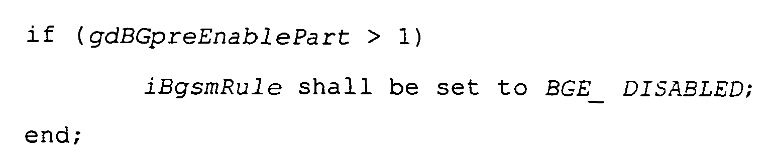
- Starting with macrotick gdActionPointOffset of the symbol window the following rule shall be applied:

- Starting with macrotick gdActionPointOffset + 1 iBgsmRule shall be set to BGE_ENABLED.
- Starting with macrotick pdBgeSymbolDuration + gdActionPointOffset the following rule shall be applied:


- Starting with macrotick pdBgeSymbolDuration + gdActionPointOffset + 1 the following rule shall be applied:

- Starting with the first macrotick of the network idle time the following rule shall be applied:

- Starting with the second macrotick of the network idle time iBgsmRule shall be set to BGE_DISABLED.
- A time triggered communication mode, where the timebase is generated either by a distributed clock algorithm or under control of a communication master
- An event triggered communication mode
- A mechanism that allows the host to initiate a communication cycle via the CHI. There are many means by which this could be accomplished. An example is a CHI element that, when written by the host, would cause the initiation of a communication cycle. If the host initiates a new trigger during a communication cycle, a new communication cycle shall be triggered immediately after the end of the current communication cycle.
- A configurable timer to initiate periodic communication cycles. The CHI provides a function to start / stop the timer. If the timer is enabled a communication cycle is started when the timer expires.
- A direct hardware input to the Communication Controller to trigger the communication cycle by an external hardware pin. The CHI gives the host the opportunity to configure the direct hardware input (enable/disable, edge sensitivity, etc.).
8. In the event triggered communication mode bus guardian protection is not required.
- Slave nodes can react on a trigger event on the master node with minimal time delay on the assumption of the FlexRay media access scheme. Therefore the re-use of the FlexRay media access scheme is possible.
- Cycle counter will be incremented in the master and the slave at the (cycle start). Therefore nearly the same frame acceptance method can be applied
- Re-ordering of the messages in the dynamic part can be done within the NIT
The arbitration grid level builds on the macrotick level that is defined by the macrotick. The macrotick is specified in Chapter "Clock Synchronization". Specific macrotick boundaries are called action points. These are dedicated instants at which transmissions shall start (in the static segment, dynamic segment and symbol window) and shall end (only in the dynamic segment).
If at least one valid frame with
- Single channel connected slaves
- If the cycle counter of the received frame with Id = 1 is not equal to the local cycle counter then the local cycle counter shall be changed to the cycle counter received in frame with ID = 1. This will be indicated by an S_CycleCountError. The frame with ID = 1 is accepted normally, and the remainder of the communication cycle is executed normally.
- In all other cases the local cycle counter shall remain unchanged, the frame shall continue through the acceptance process, and the communication cycle shall be executed normally
- Dual channel connected slave
- If the cycle counts of all received frames with Id = 1 are identical but not equal to the local cycle counter then the local cycle counter shall be changed to the cycle counter received in the frames with ID = 1 (If only one frame is received then it is identical by default.). This will be indicated by an S_CycleCountError. The frame(s) with ID = 1 are accepted normally, and the remainder of the communication cycle is executed normally.
- In all other cases the local cycle counter shall remain unchanged, the frame(s) shall continue through the acceptance process, and the communication cycle shall be executed normally
- The timing of the CC trigger is monitored by the master.
- The cycle-to-cycle timing of the EIS symbol, sent by the master, is monitored by the slaves.
- In normal operation the CC trigger appears later than pdExTrigCycleMin and earlier than pdExTrigCycleMax. No error is signaled and the start of a new communication cycle is initiated by the CC trigger. The start of a new CC trigger window is computed when the CC trigger arrives.
- If the CC trigger does not appear before pdExTrigCycleMax, an EXT_TRIG_LIF (CC Trigger Lost Interrupt Flag) error is signaled after pdExTrigCycleMax. The start of a new trigger window will be determined only after the actual arrival of a new CC trigger. As long as no new CC trigger arrives, no new communication cycle is initiated. It is up to the host to initiate the communication cycle if needed.
- If the CC trigger appears earlier than pdExTrigCycleMin, the EXT_TRIG_EIF (CC Trigger Early Interrupt Flag) error is signaled immediately. No communication cycle is initiated, and no new trigger window is determined in this case.
- In normal operation the end of the EIS appears later than pdEISSymbCycleMin but earlier than pdEISSymbCycleMax. No error is signaled. The start of a new EIS window is computed when the end of the EIS arrives.
- If no valid EIS is received such that the end of the EIS appears before pdEISSymbCycleMax, an EIS_SYMB_LIF (EIS symbol Lost Interrupt Flag) error is signaled after pdEISSymbCycleMax. When an EIS symbol arrives, the slaves continue with a new communication cycle.
- If the end of the EIS symbol appears earlier than pdEISSymbCycleMin the early EIS symbol is ignored, and an EIS_SYMB_EIF (EIS Symbol Early Interrupt Flag) error is signaled immediately. The node switches into a passive mode, stopping all frame transmission and reception. No new EIS window is computed, and no new communication cycle is initiated. The slave node waits for another EIS symbol after pdEISSymbCycleMin.
- State transitions with a prefix of 'G' are global transitions for the FlexRay protocol.
- State transitions with a prefix of 'L' indicate states transitions corresponding to logical conditions
- State transitions with a prefix of 'E' are transitions specific to the event triggered communication mode.
| State Transition | Transition Direction | Conditions for Transition | Action taken on Transition | ||
| From State | To State | ||||
| L3 | CC_Normal | CC_SoftReset | A CC_Reset is requested by the host | The ongoing frame transmission or reception is allowed to proceed to completion and the configuration data shall be retained | |
| L4 | CC_SoftReset | Initialization is finished | |||
| G5 | CC_SoftReset | CC_WaitEIS | soft reset released (in the respective control register) | Reset timer for EIS symbol monitoring | |
| AND | Event Triggered slave mode is configured | ||||
| G6 | CC_WaitEvent | soft reset released (in the respective control register) | Reset timer for event trigger monitoring | ||
| AND | Event Triggered master mode is configured | ||||
| E1 | CC_WaitEIS | CC_WaitSlaveNIT | Reception of a valid EIS with the end later than pdEISSymbCycleMin | set vEDMTimer to pdSlaveEIStoEndOf NIT, set EIS_REC_INT interrupt Reset timer for EIS symbol monitoring | |
| E2 | CC_WaitEIS | Reception of a valid EIS with the end earlier than pdEISSymbCycleM in | Signal EIS_SYMB_EIF (EIS symbol Early Interrupt Flag) Error (Note - The EIS timer is not reset by this transition) | ||
| E3 | CC_WaitEIS | EIS Timer reaches pdEISSymbCycleMax without detecting a valid EIS | Signal EIS_SYMB_LIF (EIS symbol Lost Interrupt Flag) Error (Note - The EIS timer is not reset by this transition) | ||
| E4 | CC_WaitSlaveNIT | CC_WaitID1 | vEDMTimer expires (i.e., pdSlaveEIStoEnd OfNIT has elapsed) | Reset vMacrotick, microtick counter, increment cycle counter | |
| E5 | CC_WaitID1 | CC_NormalSlave | Reception of a valid frame with ID 1 (This implies that the cycle counter match check has also passed (i.e., the local cycle counter matches the received cycle counter).) | ||
| E6 | CC_NormalSlave | Reception of a frame with | Signal S_CycleCountError Error The received cycle count is applied for the local cycle count value | ||
| E7 | CC_WaitEIS | The end of | Signal S_Trig_Symb_Failure Error | ||
| E8 | CC_NormalSlav e | CC_WaitEIS | End of dynamic segment reached (vMacrotick== gdCycle -gdNetworkIdleTime - gdSymbolWindow; based on local timers) | Reset timer for EIS symbol monitoring | |
| E9 | CC_WaitEvent | CC_WaitMaster NIT | CC trigger appears later than pdExTrigCycleMin | send EIS symbol set EXT_SOR_INT interrupt set vEDMTimer to pdMasterEIStoEndO fNIT | |
| E10 | CC_WaitMasterNIT | Trigger bit is set by host | send EIS symbol set vEDMTimer to pdMasterEIStoEndO fNIT | ||
| E11 | CC_WaitEvent | CC trigger appears earlier than pdExTrigCycleMin | Signal EXT_TRIG_EIF (CC trigger Early Interrupt Flag) Error (Note - The CC trigger timer is not affected by this transition) | ||
| AND | Trigger source is external event | ||||
| E12 | CC_WaitEvent | CC trigger timer reaches pdExTrigCycleMax before a CC trigger appears | signal EXT_TRIG_LIF (CC trigger Lost Interrupt Flag) Error (Note - The CC trigger timer is not affected by this transition) | ||
| E13 | CC_WaitMasterNIT | CC_NormalMaster | vEDMTimer expires (i.e., pdMasterEIStoEndOfNIT has elapsed) | Reset vMacrotick, and vMicrotick counters, increment cycle counter, reinitialize error signaling counters, send frame ID 1 in slot 1 | |
| E14 | CC_WaitMaster NIT | CC trigger appears | Signal EXT_TRIG_EIF (CC trigger Early Interrupt Flag) Error | ||
| AND | Trigger source is external event | ||||
| E15 | CC_NormalMaster | CC_WaitEvent | End of dynamic segment reached (vMacrotick== gdCycle - gdNetworkIdleTime - gdSymbolWindow; based on local timers) | Reset timer for event trigger monitoring | |
| E16 | CC_NormalMaster | CC trigger appears | Signal EXT_TRIG_EIF (CC trigger Early Interrupt Flag) Error | ||
| AND | Trigger source is external event | ||||
- Event triggered mode specific requirements:
- A configuration parameter (e.g. pMasterSelect or consider reusing pSyncMaster) defines whether the node acts as a master or as a slave.
- For the master node three event sources for starting the next cycle exist: external event, host access, CC internal timer (normal cycle length). The host decides during runtime which event source(s) are used.
- The trigger/event sources external event and CC internal timer can be enabled / disabled independently. If more than one source is enabled, the first event arms the CC to send the EIS symbol. At least one of the triggers sources has to be enabled.
- Product specific: The behavior of the input signal for the external source should be configurable with respect to the trigger type (falling or rising edge) and the assignment to a trigger pin.
- Product specific: Upon detection of the trigger event, the master CC shall capture the macrotick-counter and present this value to the host.
- Product specific: Upon reception of the trigger event, the master CC shall indicate this immediately to the host (Event Trigger).
- Product specific: Upon reception of the event indication symbol, the slaves shall capture their macrotick-counters.
- Upon reception of the event indication symbol, the slave shall indicate this immediately to the host (Event Indication Symbol (EIS) Detected).
- It is required for the host to be able to change the transmit buffers during the dynamic segment in the following way:
- The data of a buffer may be changed.
- The data and the ID of a buffer may be changed as long as its order in the list of dynamic IDs is not changed
- Range of pdExTrigCycleMin: 100 µs ... 64 ms
- Range of pdExTrigCycleMax: 100 µs ... 64 ms
- Range of pdEISSymbCycleMin: 100 µs ... 64 ms
- Range of pdEISSymbCycleMax: 100 µs ... 64 ms
| General Interrupt Flag | Bits | | Channel |
| EXT_SOR_INT | |||
| 1 | External source interrupt (master only) | - | |
| | 1 | External Trigger Early Interrupt Flag, external trigger received before pdExTrigCycleMin (master only) | - |
| | 1 | External Trigger Late Interrupt Flag, external trigger not received before pdExTrigCycleMax (master only) | - |
| | 1 | EIS symbol detected | A |
| | 1 | EIS symbol Early Interrupt Flag, EIS received before | A |
| EXT_TRIG_LIF | |||
| 1 | EIS symbol Lost Interrupt Flag, EIS not received before | A | |
| EIS_REC_INT | |||
| 1 | EIS symbol detected | | |
| EXT_TRIG_EIF | |||
| 1 | EIS symbol Early Interrupt Flag, EIS received before | B | |
| EXT_TRIG_LIF | |||
| 1 | EIS symbol Lost Interrupt Flag, EIS not received before pdEISSymbCycleMax | B |
| Note: It is possible to use the external source interrupt (EXT_SOR_INT) even if the external source is not used in order to gather information about the occurrence of external source trigger events. |
- 5 bits to identify the silicon manufacturer
- 4 bits for manufacturer defined silicon versions
- 7 bits to identify the implemented protocol version.
- vCCMS; Coldstart max reached (vColdStartCount = gColdStartMax)
- vSMMS, Plausibility check failed
- vOpViaColdstart; Normal state entered via coldstart path
- vColdStartAborted; Coldstart aborted because of CAS or Sync Frame received
- vColdstartNoise; Coldstart path has been entered due to the expiration of pColdstartNoise
- Frame Header Received during Wakeup flag (vWakeupFrameHeaderReceived). This flag shall be set if due to the reception of a frame header without coding violation the CC stops the wakeup.
- Wakeup Symbol Received flag (vWakeupSymbolReceived). This flag shall be set if due to the reception of a valid Rx-wakeup symbol the CC stops the wakeup.
- Wakeup Failed flag (vWakeupFailed). This flag shall be set if due to too many wakeup tries the CC stops the wakeup.
- Wakeup Complete flag (vWakeupComplete). This flag shall be set if the CC has completed the transmission of the Tx-wakeup.
- CC_SoftReset State
- CC_Normal State
- CC_ShutdownRequest State
- CC_Shutdown Complete State
- CC_Standby State
- Listen-Only Mode
- WakeUPListen State
- StartupListen State
- ColdStartICW State
- ColdStartVCW State
- IntegrationVCW State
- PassiveOperation State
- Event Triggered Mode
- Soft Reset
When this bit is set by the host, the CC shall immediately enter the CC_SoftReset State. Any ongoing transmission or reception shall be aborted and synchronization to the ongoing communication shall be stopped. When this bit is cleared by the host, the CC shall enter the Normal State and start the reintegration or startup. If wake-up is configured, the CC shall enter the WakeUPListen State after leaving CC_SoftReset. The CC shall enter the CC_SoftReset State automatically after power on reset. The host shall configure the CC in this state. When the host forces the CC into soft reset, the status and error registers should keep their data unchanged until the soft reset is terminated. (Transition L5 and L6 of the HW state machine; see Section 'CC State Diagram')) - Listen-Only Select
When this bit (vListenOnly) is set, the CC shall be able to receive all frames after successful integration to the running communication. In comparison to the normal operation mode the node does not actively participate in communication, i.e. neither symbols nor frames are transmitted. This bit can be set only in CC_SoftReset State to true, but can be cleared any time by the host. (See Section 'Listen-Only Mode') - Master Select
This bit (pSyncMaster) selects the CC as a bus master in the Master Controlled Operating modes. (See Section 0) The CC shall send the Event Indication Symbol and the static sync frame when the bit is set. The CC shall ignore any attempt to change the status of this bit when not in CC_SoftReset State. - Master Alarm
If the Master Select and the Master Alarm bits are set, the CC shall send an SAS symbol in the byteflight mode. The bit can be set and reset by the host any time during normal operation. - Shutdown Request
When this bit is set by the host, the CC shall enter the CC_ShutdownComplete state (see Section 'CC_ShutDownComplete State'). In this state all internal clocks shall be stopped after finishing the current communication round. The state can be left by the host resetting the bit. - Standby Request
When this bit is set by the host, the CC shall enter the CC_StandByRequest State. In this state all internal clocks shall be stopped after the CC has completed any ongoing transmission and reception. The CC shall leave this state upon the host resetting the bit or upon wake-up activity being signaled by the physical layer on the Rx input. - Send Wakeup
When this bit is set by the host, the CC shall enter WakeUPListen State when leaving the CC_SoftReset State and send the Wakeup Pattern. The CC shall ignore any attempt to change the status of this bit when not in CC_SoftReset State. (See Section 'Waking One Channel') - Wakeup Channel Select
With this bit (vWakeupChannel) the host selects the channel on which the CC shall send the Wakeup Pattern ('0'= channel A, '1'= channel B). The CC shall ignore any attempt to change the status of this bit when not in CC_SoftReset State. (See Section 'Waking One Channel') - Event Triggered Mode Select
When this bit is set by the host, the CC shall operate in the Event Triggered Mode. This bit shall be reset by default (= Time Driven Mode), and the CC shall ignore any attempt to change the status of this bit when not in CC_SoftReset State. - External Trigger Acceptance
When this bit is set by the host, the CC shall accept an external trigger to send the Event Indication Symbol and the static sync frame in the Event Triggered Mode, if the CC is configured as a master (Master Select bit set). The CC shall ignore any attempt to change the status of this bit when not in CC_SoftReset State. - Message/Frame ID Filtering
When this bit (gMsgIdFilter) is set by the host, the CC shall apply the configured Message ID filtering for all dedicated receive and FIFO receive mailbox buffers as described inSection 0. If this bit is not set (by default) the CC shall apply the Frame ID filtering. The CC shall ignore any attempt to change the status of this bit when not in CC_SoftReset State. It should be configured identically in all nodes of a cluster. - byteflight Compatibility mode
This bit selects the byteflight Compatibility mode when set. The CC shall ignore any attempt to change the status of this bit when not in CC_SoftReset State.
- The CC shall provide a register to configure the number of FIFO receive buffers as a part of all available message buffers. The CC shall ignore any attempt to change the content of the register when not in CC_SoftReset. (See below).
- The CHI shall provide three registers to configure the timing parameters TCR1, TCR2, TCR3 required for the byteflight compatibility mode. These parameters are not used in all the other operating modes of the CC.
- TCR1
- 8 bit; to configure the timing parameter pdWx0Rx, a constant component of vdWaitTime in the dynamic section in the case that the most recent bus activity was received by the local node; may be modified only in CC_SoftReset.
- TCR2
- 8 bit; to configure the timing parameter pdWx0Tx, a constant component of vdWaitTime in the dynamic section in the case that the most recent bus activity was transmitted by the local node; may be modified only in CC_SoftReset.
- TCR3
- 10 bit; to configure the timing parameter gdWxDelta a multiplier part of vdWaitTime. The value chosen must be identical for all nodes in the cluster, and may be modified only in CC_SoftReset. It shall be calculated as follows:
- gdWxDelta = gdMaxPropagationDelay + gdMaxTolerances
- Bit Rate Index, 4 bits
- Sample Clock Prescaler, 4 bits
- Samples per bit, 2 bits (8 or 10 samples; 01b = 8, 10b = 10 samples)
- (See Section 'Coding and Decoding - Configuration Parameters' for details)
- The CC shall accept modifications of the register only in CC_SoftReset.
- Cycle Set - A 9-bit register is used to specify in which set of cycles the interrupt shall occur. It consists of two fields, the Base Cycle [b] and the Cycle Repetition [c]. The set of cycle numbers where the interrupt is to be generated is determined from these two fields using the formula

- Base Cycle [b] - A 6-bit cycle number used to identify the initial value for generating the cycle set
- Cycle Repetition [c] - A 3-bit value used to determine a constant repetition factor to be added to the base cycle (c = 0 ... 6).
- Macrotick Offset - This 16-bit value is the macrotick offset from the beginning of the cycle where the interrupt is to occur. The interrupt occurs at this offset for each cycle in the Interrupt Cycle Set.
- 6 bits; to configure the duration of the active low level (gdWakeupSymbolTxLow) of the wake-up symbol in multiples of bit times (gdBit); may be modified only in CC_SoftReset.
- 8 bits; to configure the duration of the idle/recessive high level (gdWakeupSymbolTxIdle) of the wake-up symbol in multiples of bit times (gdBit); may be modified only in CC_SoftReset.
- 4 bits; to configure the number of repetitions (sequences) (pdWakeupPattern) of the wake-up symbol; may be modified only in CC_SoftReset.
- 6 bits; to configure the minimum duration of the active low level (gdWakeupSymbolRxLow) in multiples of bit times (gdBit) for the receiver to recognize the symbol as a wake-up; may be modified only in CC_SoftReset.
- 6 bits; to configure the minimum duration of the idle/recessive high level (gdWakeupSymbolRxIdleMin) in multiples of bit times (gdBit) for the receiver to recognize the symbol as a wake-up; may be modified only in CC SoftReset.
- 9 bits; to configure the window length within which the symbol has to be received (gdWakeupSymbolRxWindow) in multiples of bit times (gdBit) for the receiver to recognize the symbol as a wake-up; may be modified only in CC SoftReset.
- 4 bits; to configure the maximum number of times (gWakeupMax) the CC is permitted to autonomously attempt to send a wake-up pattern; may be modified only in CC_SoftReset.
- 6 bits; to configure in multiples of bit times (gdBit) the duration of the active low level on the bus (gdWakeupMaxCollision) that a CC sending a wake-up pattern shall accept during the idle phase of the pattern without reentering the WakeupListen state; may be modified only in CC_SoftReset.
- There are matching frame IDs and cycle counters, but none of these transmit buffers has the "Commit" flag set.
- All transmit buffers configured for the slot have cycle filters that do not match the current cycle (see below).
| Status/Error Flag | Bits | Tx Buffer | Rx Buffer | FIFO Buffer |
| Null Frame (static segment only) | 1 | Null Frame transmitted | Null Frame received | Null Frame received |
| Empty Slot (static segment only) | 1 | - | No bus traffic detected | - |
| Bit Coding/CRC Error | 1 | - | Error detected (bit coding, header or frame CRC, in static segment only) | - |
| Length Mismatch | 1 | - | Length Mismatch detected (static segment only) | - |
| Slot Mismatch | 1 | - | Slot Mismatch detected | - |
| Cycle Counter Mismatch | 1 | - | Cycle Counter Mismatch detected (static segment) | - |
| | 1 | Start of transmission during ongoing reception | Start of Transmission during ongoing Reception | - |
| Empty Slot on second channel | 1 | - | No bus traffic detected on the other channel (static segment only) | - |
| Receive Error on second channel | 1 | - | Receive Error detected on the other channel (static segment only) | - |
- Channel Number
- Frame Id
- Cycle Counter
- Message Id
- Receive buffer: In order to store a message the filters for channel Id, and cycle counter must match. In addition, depending on the configuration bit gMsgIdFilter (see Section 0) either the Frame Id (gMsgIdFilter = '0') or the Message Id (gMsgIdFilter = '1') must match (but not both).
- Transmit buffer: A frame shall be transmitted in the time slot corresponding to the frame ID on the configured channel(s) if the cycle counter matches the configured cycle filter value.
- Receive buffer: received frames shall be stored if they are received on all the specified in the Channel Filtering Field. Other filtering criteria must also be met.
- Transmit buffer: the content of the buffer is transmitted only on the channels specified in the Channel Filtering Field when the Cycle Counter Filtering and Frame Id Filtering criteria are also met.
| Config. bit A | Config. bit B | Tx Buffer Transmit frame | Rx Buffer Store |
| 1 | 1 | on both channels | received on channel A or B (pick first valid) |
| 1 | 0 | on channel A | received on |
| 0 | 1 | on channel B | received on |
| 0 | 0 | no transmission | ignore frame |
- Receive message buffers: A received message is stored in the first receive message buffer where the received frame ID matches the receive mailbox frame ID, provided gMsgIdFilter = '0' and the other receive filtering criteria are also met. If Message Id filtering is being used (gMsgIdFilter = '1'), this filter is not applied.
- For Transmit buffers the frame ID in the buffer is used to determine the appropriate slot for the message transmission. The frame shall be transmitted in the time slot corresponding to the frame ID, provided the channel and cycle counter criteria are also met.
- Cycle Set -
A 9 bit register is used to specify which cycle numbers are elements of the set. It consists of two fields, the Base Cycle [b] and the Cycle Repetition [c]. The set of cycle numbers belonging to the set shall be determined from these two fields using the formula
- Base Cycle [b] -
A 6 bit cycle number used to identify the initial value for generating the cycle set - Cycle Repetition [c] -
A 3 bit value used to determine a constant repetition factor to be added to the base cycle (c = 0 ... 6).
- Base Cycle [b] -
- Receive buffer: The received message is stored only if the received cycle counter matches an element of the buffer's Cycle Set. Channel, Frame Id or Message Id criteria must also be met.
- Transmit buffer: The content of the buffer is transmitted when an element of the Cycle Set matches the current cycle counter and the frame ID matches the slot counter value. If the cycle counter does not match any cycle counter filter criteria from the configured transmit buffers with matching frame ID, a Null Frame shall be transmitted in the static segment. (See below).
| General Interrupt Flag | Bits | Receiver | Channel |
| Bit Coding/ | 1 | Error detected (bit coding, header or frame CRC) | A |
| | 1 | Slot Mismatch detected | A |
| | 1 | Cycle Counter Mismatch detected | A |
| | 1 | Length Mismatch detected | A |
| | 1 | Unexpected symbol reception | |
| Symbol Normal | |||
| 1 | Symbol Normal received | A | |
| | 1 | Symbol Alarm received | A |
| Bit Coding/ | 1 | Error detected (bit coding, header or frame CRC) | |
| Slot Mismatch | |||
| 1 | Slot Mismatch detected | B | |
| | 1 | Cycle Counter Mismatch detected | |
| Length Mismatch | |||
| 1 | Length Mismatch detected | | |
| Unaccepted Symbol | |||
| 1 | Unexpected symbol reception | | |
| Symbol Normal | |||
| 1 | Symbol Normal received | | |
| Symbol Alarm | |||
| 1 | Symbol Alarm received | B |
- Receive Interrupt Flag
- The flag shall be set by the CC when a frame was received and stored in one of the dedicated receive buffers.
- Receive FIFO Not Empty Interrupt Flag
- The flag shall be set by the CC when a frame was received and stored in one of the FIFO buffers.
- Receive FIFO Overrun Interrupt Flag
- The flag shall be set by the CC when a Receive FIFO Overrun was detected.
- Collision Avoidance Symbol Interrupt Flag
- The flag shall be set by the CC when a CAS was received.
- Wake-up Symbol Interrupt Flag
- The flag shall be set by the CC when a Wake-up Symbol was received.
- Media Access Test Symbol Flag
- The flag shall be set by the CC when a MTS was received.
- Event Indication Symbol Flag
- The flag shall be set by the CC when an EIS was received.
- Optical Diagnosis Flag
- The flag shall be set by the CC when an optical diagnosis signal was received.
- Status Normal Symbol Flag
- The flag shall be set by the CC when a SNS was received.
- Status Alarm Symbol Flag
- The flag shall be set by the CC when a SAS was received.
- Network Management Vector Change Flag
- The flag shall be set by the CC when the optional NM services are implemented, and a change in the NM vector occurred. (See below)
- Clock Correction Failure; This flag enables an interrupt whenever one of the following errors occur:
- Missing Rate Correction Signal (MRCS)
- Missing Offset Correction Signal (MOCS)
- Clock Correction Failed Counter (CCFC) stopped at 15
- Clock Correction Limit Reached (CCLR)
- The interrupt shall be raised at the end of the cycle after the listed errors have been checked.
- Protocol Error State; This flag enables an interrupt whenever the error state will change from "Green" to "Yellow" or to "Red".
- Startup: This flag enables an interrupt whenever one of the following events occur:
- Coldstart max reached
- Coldstart path has been entered due to the expiration of pStartupNoise
- Normal state entered via coldstart path
- Plausibility check failed (during startup)
- Bus Guardian Schedule Monitoring Error (BGME)
- Media Access Test Warning
- Wakeup; This flag enables an interrupt whenever one of the following events occur:
- Frame Header Received during Wakeup
- Wakeup Symbol Received
- Wakeup Failed
- Wakeup Complete
- four bits to configure the length of the NM vector (gNetworkManagementVectorLength), (0 to 12 bytes); may be modified only in CC_SoftReset. The configured length must be identical in all nodes of a cluster.
- one bit to configure the starting point of the NM vector in the data field (
byte 0 if bit not set,byte 2 if bit set); may be modified only in CC_SoftReset. The configured starting point must be identical in all nodes of a cluster. - one register (with in the implementation specified 8 to 12 bytes) to hold the NM vector as a result of a logical OR operation over all received NM vectors in the previous cycle. The CC shall perform the OR operation over all NM vectors out of all received NM frames with the fNMIndicationBit set. (See Section 'Network Management Indication Bit') The CC shall update the NM vector at the end of the cycle.
- one interrupt flag to signal a change in the NM vector visible to the host.
- one interrupt enable bit.
- Two Optical Diagnosis Flags (one for each channel)
- The flags shall be set by the CC when too low optical power was received by the optical transceiver and signaled to the CC. If the host checks the flags, it must reset them so that the CC can update them.
| Control Flag | Bits | Tx Buffer | Rx Buffer | FIFO Buffer | Comment |
| CFG | 1 | '1' = Transmit Buffer | '0' = Receive Buffer | '0' | Message Buffer Configuration Bit |
| CFG_SR | 1 | '1' = Mailbox Buffer and the associated filter can be configured only during CC_SoftReset. | '1' = Buffer and the associated filter can be configured only during CC_SoftReset. | - | '0' = Mailbox Buffer and the associated filter can be configured during normal operation. |
| Transmis sion Mode | 1 | '1' = Single-shot Mode (transmit Null Frame if buffer not updated, Commit flag = '0') '0' = Continuous Mode (See above) | - | - | only for static slots |
| Commit Flag | 1 | '0' = buffer not updated, '1' = buffer committed for transmission; Host explicitly sets the Commit flag when the buffer is ready for transmit. The Commit flag is reset by the CC after transmission has been completed in the "Single-shot" mode only. (See above). | '1' = buffer updated (valid), '0' = not updated; Host shall explicitly clear the flag after reading the data. | - | Commit Flag |
| IENA | 1 | '1' = Interrupt enabled | '1' = Interrupt enabled | - | Commit Interrupt Enable |
| ABTRQ | 1 | '1' = Abort request; Message shall be aborted at next start of cycle if transmission has not been started before. | - | - | Abort Request |
| ABTAK | 1 | '1' = Message has been aborted. | - | - | Abort Acknowledge |
| LOCK | 1 | '1' = lock, '0' = release | '1' = lock, '0' = release | - | Message Buffer Lock. A locked buffer is visible to the host. |
| (Note: The host can modify the control flags CFG and CFG_SR only during CC_SoftReset.) |
| Event | Description |
| Status Normal Symbol (SNS)detected on bus | SET_SNSIF |
| Status Alarm Symbol (SAS) detected on bus | SET_SASIF |
| Correct message was received which may be copied into a receive buffer | SET_RCVMSG, even if message is not copied into any buffer (in case no adequate receive buffer is configured) |
| One of following errors detected during the receive process: | SET_ERRIF |
| S_TssViolation, S_HeaderCodingError, S_InvalidHeaderCRC, S_FrameCodingError, S_InvalidFrameCRC. (See Section 'Syntactical Correctness') | |
| Slot mismatch detected (S_FrameIDError). (See Section 'Frame Acceptance') | SET_SLMM |
| Name | Description | Value | Unit | |
| cControllerMax | The maximum number of nodes in a cluster | 64 | - | |
| cCycleMax | The maximum cycle counter in a cluster | 63 | - | |
| cMaxChannels | The maximum number of supported channels | 2 | - | |
| cPaddingValue | Value of the data byte used for padding of static frames in case pMaxPayloadLength is smaller than fPayloadLength | 0 | - | |
| cPayloadLengthMax | Maximum length of the payload segment of a frame | 127 | 2-byte words | |
| cSlotIDMax | The highest slot ID number | 4095 | - | |
| cStarCouplersMax | The largest allowed number of cascaded star couplers between any two nodes in a cluster | 3 | - | |
| cSyncNodeMax | The maximum possible number of sync nodes | TBD | - |
| Name | Description | Range | Unit | |
| gchannels | The number of channels supported by the cluster. Note: there is also a node constant pChannels, which reflects the connectivity of each specific node | 1 - cMaxChannels | - | |
| gColdStartMax | The maximum number of times that a node in this cluster is permitted to attempt to start the cluster by initiating schedule synchronization | 0 - TBD | - | |
| gdActionPointOffset | The offset of the action point | 1 - TBD | MT | |
| gdBGArmActive | Duration of the Bus Guardian ARM signal |
1 | MT | |
| gdBGDynSegment | Bus Guardian dynamic segment length | 0 - 65534 | MT | |
| gdBGpostEnablePart | Bus Guardian ISG part that follows a guarded schedule element | 0 - TBD | MT | |
| gdBGpreEnablePart | Bus Guardian ISG part that precedes a guarded schedule element | 0 - TBD | MT | |
| gdBGStaticSlot | Bus Guardian Static slot length (Does not include the inter-slot gap.) | 0 to 4095 | MT | |
| gdBGSymbolWindow | Bus Guardian |
0 to 255 | MT | |
| gdBGWatchdogDisable | Bus Guardian watchdog disable |
1 to 255 | MT | |
| gdBit | The configured duration of one bit. The value is derived from gBitRate. | TBD | ns | |
| gdCycle | The duration of one communication cycle in this cluster | 250 - 64000 | µs | |
| gdCycleMax | Maximum duration of a byteflight communication cycle | TBD | ?? | |
| gdCycleMIn | Minimum duration of a byteflight communication cycle | TBD | ?? | |
| gdDynamicSlotIdlePh ase | The duration of the dynamic slot idle phase | 1 - TBD | Minislo ts | |
| gdInitialColdStartP hase | Period for which a node remain in CC_ColdStartICW state, if no incident causes the transition into CC_StartupListen beforehand; this is not a |
3* gdCycle + gdSlot | MT | |
| gdMaxDrift | Maximum drift offset between two node that operate with unsynchronized clocks over one communication cycle | TBD | MT | |
| gdMedPropagationDel ay (not a global constant) | The medium expected propagation delay of a signal (including transceiver delays, wire delays and controller internal delays) in the cluster | TBD | µT | |
| gdMinislot | The duration of a minislot | 2 - TBD | MT | |
| gdMsActionPointOffs et | The offset of the action point within the minislot | 1 - TBD | MT | |
| gdNIT | The duration of the network idle time | TBD - TBD | MT | |
| gdStartup | Upper limit for the listen-timeout in CC_StartupListen state (before a sync node is allowed to become a coldstart node). See also vdStartup. | gdStartup = gdCycle + gdMaxDrift | MT | |
| gdStaticSlot | The duration of a static slot. | 2 - TBD | MT | |
| gdSymbolWindow | The duration of the symbol window | 0 - TBD | MT | |
| gSyncNodeMax | The maximum number of sync nodes allowed for this cluster | 0 - 16 | - | |
| gdWakeup | Upper limit for the listen-timeout in CC_WakeupListen state (before a sync-Node is allowed to transmit the Tx-wakeup pattern); (this is not a configuration parameter) | gdWakeup = gdStartupt = gdCycle + gdMaxDrift | MT | |
| gdWakeupMaxCollision | Duration of 'active low' on the bus that a communication controller sending a Tx-wakeup pattern accepts during the idle phase of the pattern without re-entering the CC_WakeupListen state. | TBD | gdBit | |
| gdWakeupPattern | Maximal number of repetitions of the Tx-wakeup symbol to be sent during the CC_WakeupSend state of any Node in the cluster. | 15 | - | |
| gdWakeupSymbolRxIdl eMin | The equivalent of 6µs minus a safe part. (Collisions, clock differences and other effects can deform the Tx-wakeup pattern.) To be used by the communication controller for the 'idle' part of the CheckRxWakeupSymbol test | TBD | gdBit | |
| gdWakeupSymbolRxLow | The equivalent of 6ps minus a safe part. (Active stars, clock differences and other effects can deform the Tx-wakeup pattern.) To be used by the communication controller for the 'active low' parts of the CheckRxWakeupSymbol test | TBD | gdBit | |
| gdWakeupSymbolRxWin dow | The equivalent of 30µs plus a safe part. (Clock differences and other effects can deform the Tx-wakeup pattern.) To be used by the communication controller for the CheckRxWakeupSymbol test | TBD | gdBit | |
| gdWakeupSymbolTxIdle | The equivalent of 18µs (rounded up). To be used by the communication controller for the transmission of the 'idle' part of the Tx- |
TBD | gdBit | |
| gdWakeupSymbolTxLow | The equivalent of 6ps (rounded up). To be used by the communication controller for the transmission of the 'active low' part of the Tx-wakeup symbol | TBD | gdBit | |
| gMacroPerCycle | The configured duration of the cluster cycle in macroticks | TBD | MT | |
| gMaxWithoutClockCor rectionFatal | Threshold concerning CCFC. Defines when the CC shall change from green or yellow into red error state | [gMaxWithou tClockCorre ctionPassiv e - 15] | Number of even / odd cycle pairs | |
| gMaxWithoutClockCor rectonPassive | Threshold concerning CCFC. Defines when the CC shall change from green into yellow error state | 1 - 7 | Number of even / odd cycle pairs | |
| gMsgIdFilter | Indicates that Message ID filtering is used within the cluster and that the first two bytes of the payload segment contain Message ID data | Boolean | - | |
| gNetworkManagementV ectorLength | Length of the Network Management vector in a cluster | 0 - 12 | Bytes | |
| gNumberOfMinislots | The duration of the dynamic segment | 0 - TBD | Mini slots | |
| gNumberOfStaticSlot s | The number of static slots in the static segment. | 1 - cSlotIDMax. | Slots | |
| gOffsetCorrectionIn itOut | The maximum offset value permitted for the first offset correction in CC_IntegrationVCW state. (This constant is the basis for the calculation of the controller specific parameter (see pOffsetCorrectionlnitOut)) | TBD | MT | |
| gOffsetCorrectionOu t | The maximum offset correction permitted. (This constant is the basis for the calculation of the controller specific parameter (see pOffsetCorrectionOut)) | TBD | MT | |
| gPayloadLengthStati c | Globally configured payload length of a static frame | 0 - cPayloadLengthMax | 2-byte words | |
| gRateCorrectionOut | The maximum rate correction permitted (This constant is the basis for the calculation of the controller specific parameter (see pRateCorrectionOut)) | TBD | MT | |
| gStartupNoise | Upper limit for the start up listen timeout in the presence of noise. Expressed as a multiple of the cluster constant gdStartup. | TBD | - | |
| gSyncNodeMax | The maximum number of sync nodes allowed in the cluster | 1 - cSyncNodeMax | - | |
| gWakeupMax | The maximum number of times that a Node in this cluster is permitted to attempt to send a Tx-wakeup pattern. | TBD | - | |
| gWakeupNoise | Upper limit for the wakeup listen timeout in the presence of noise. Expressed as a multiple of the cluster constant gdWakeup. this is not a configuration parameter! | gWakeupNois e = gStartupNoi se | - | |
| gWakeupPattern | Number of repetitions of the Wakeup symbol | 2 - TBD | - |
| Name | Description | Range | Unit | |
| gdBGMinMTNom | Minimum nominal MT period | 1.0 | µs | |
| gdBGMInMTCorr | Minimum corrected MT period | 0.5 | µs | |
| gdBGMinBGTPeriod | Minimum BGT period | 0.25 | µs | |
| gdBGMinPwMT | Minimum MT pulse width (low or high) | 0.4 * pdMTPeriod | - | |
| gdBGMinPwBGT | Minimum BGT pulse width (low or high) | 0.4 * pdBGTPerio d | - |
| Name | Description | Range | Unit | |
| pBGDynSegEnable | Indicates that a bus guardian enables transmission during the dynamic segment | Boolean | - | |
| pBGMatEnable | Indicates that a bus guardian enables the application of the media access test during the symbol window | Boolean | - | |
| pBgsmDynSegDisabled | Boolean | - | ||
| pBgsmSymWinDisabled | Boolean | - | ||
| pBGSymWinEnable | Indicates that a bus guardian enables transmission during the symbol window | Boolean | ||
| pChannels | number of channels supported by the node (Note: there is also a cluster constant gChannels) | 1 - gChannels | - | |
| pClusterDriftDampin g | Cluster drift damping value used in clock synchronization to minimize accumulation of rounding errors | TBD | µT | |
| pdBgeDynamicDuratio n | Duration of the BGE active phase during the BG dynamic segment | 0 - 65534 | MT | |
| pdBgeStaticDuration | Duration of the BGE active phase during active static slots | 0 - 4095 | MT | |
| pdBgeSymbolDuration | Duration of the BGE active phase during the BG symbol window | 0 - 255 | MT | |
| pdBGMTPeriod | Configured nominal Bus Guardian MT period | TBD | µs | |
| pdBGTPeriod | Configured Bus Guardian BGT period | TBD | µs | |
| pdCycleWithHistory | Upper limit for timeout that covers a period, which is large enough that any periodic transmission that complies to the global communication schedule is visible for an unsynchronized node at least once (Note: this is not a configuration parameter) | gdStartup | MT | |
| pdEISSymbCycleMax | Slave node, maximal appearance interval for the CC trigger | TBD | MT | |
| pdEISSymbCycleMin | Slave node, minimal appearance interval for the CC trigger | TBD | MT | |
| pDelayCompensationC hA | Value used to compensate for reception delays on channel A | µT | ||
| pDelayCompensationC hB | Value used to compensate for reception delays on channel B | µT | ||
| pdExTrigCycleMax | For the master node in an Event Triggered Mode system, maximal appearance interval for the CC trigger | TBD | MT | |
| pdExTrigCycleMin | Master node, minimal appearance interval for the CC trigger | TBD | MT | |
| pdMasterEIStoEndOfN IT | Master node, duration between reference point in the EIS symbol and begin of next cycle (which is also the end of NIT) | TBD | µT | |
| pdSlaveEIStoEndOfNI T | Slave node, duration between reference point in the EIS symbol and begin of next cycle (which is also the end of NIT) | TBD | µT | |
| pdTSS | Duration of the Transmission Start Sequence | 1 - 15 | gdBit | |
| pdWakeupPattern | Number of repetitions of the Tx-wakeup symbol to be sent during the CC_WakeupSend state. | 0 - gdWakeup Pattern | - | |
| pEdgeSamples | Width of the edge detection window in the Bit Clock Alignment procedure | TBD | - | |
| pLatestTx | The number of the last minislot in which transmission can start in the dynamic segment for the respective node | 0 - TBD | Minislo ts | |
| pMaster | Denotes that the node is configured as the sync master in byteflight mode | Boolean | - | |
| pMaxPayloadLength | Maximum number of payload data bytes stored in a message buffer | 12 - 127 | 2-byte words | |
| pMicroOverheadPer CycleNom | The node-specific initial value of the node variable vRateCorrection | TBD | µT | |
| pMicroPerMacroMax | Maximum number of microticks for one macrotick | TBD | µT | |
| pMicroPerMacroMin | Minimum number of microticks for one macrotick | TBD | µT | |
| pMicroPerMacroNom | The nominal (uncorrected) number of microticks in a macrotick | TBD | µT | |
| pOffsetCorrectionIn itOut | Parameter determining the upper and lower boundaries between the red and green areas of the clock offset correction term, applied only the first time an offset correction term is available in CC_IntegrationVCW state, expressed in node-local microticks. | TBD | µT | |
| pOffsetCorrectionOut = gOffsetCorrectionInitOut * pMicroPerMacroNom | ||||
| pOffsetCorrectionOu t | Parameter determining the upper and lower boundaries between the red and green areas of the clock offset correction term, expressed in node-local microticks. | TBD | µT | |
| pOffsetCorrectionOut = gOffsetCorrectionOut * pMicroPerMacroNom | ||||
| pRateCorrectionInit Out | Parameter determining the upper and lower boundaries for the initial rate correction allowed for rate adoption during CC_InitSync state | TBD | µT | |
| pRateCorrectionOut | Parameter determining the upper and lower boundaries between the red and green areas of the clock rate correction term, expressed in node-local microticks. | TBD | µT | |
| pRateCorrectionOut = gRateCorrectionOut * pMicroPerMacroNom | ||||
| pSamplesPerBit | The number of samples taken in the determination of a bit value | TBD | - | |
| pSyncNode | Indicates that the node is a sync node (sync slot configured; connected to gChannels) | Boolean | - | |
| pSyncSlot | The number of the static slot in which a sync frame shall be sent, if a sync frame shall be sent. | 0 - cSlotIDMax | Slots | |
| pVotingOffset | Number of samples skipped prior to the voting window in bit value voting | TBD | - | |
| pVotingSamples | Numbers of samples used in bit value voting | TBD | - |
| Name | Description | Range | Unit | |
| IbgsmRule | Local variable for BG schedule monitoring service | BGE_X, BGE_ENABLED, BGE_DISABLED | - | |
| vBgsmError | Variable indicating that the Bus Guardian Schedule Monitoring service has detected an error | Boolean | - | |
| vBgsmErrorAck | Variable allowing the host to acknowledge the detection of a Bus Guardian Schedule Monitoring error | Boolean | - | |
| vCCLR | The calculated rate correction value or calculated offset correction value is beyond the specified limit | Boolean | - | |
| vColdStartCount | Counter for number of cycles/transitions for which the node has been in the coldstart path | 0 - gColdStartMax | - | |
| vColdStartInhibit | Denotes that the node is not allowed to enter coldstart path | Boolean | - | |
| vCurrentSlot | Number of the current slot. Note that this is slightly different to fFrameID as it is independent of frame reception. | 1 - cMaxStaticSlot | slots | |
| vCycle | Cycle counter of the current communication cycle | 0 - gCycleMax | - | |
| vdCycleWithHistory | Timeout counter that covers a period, which is large enough that any periodic transmission that complies to the global communication schedule is visible for an unsynchronized node at least once | 0 - pdCycleWithHistory | MT | |
| vdInitialColdStartP hase | Timer for the period for which a node remain in CC_ColdStartICW state, if no incident causes the transition into CC_StartupListen beforehand | 0 - gdInitialColdStartPhase | MT | |
| vdStartup | Listen-timeout (counter) in CC_StartupListen state | 0 - gdStartup | MT | |
| vdStartupNoise | Listen-timeout (counter) with noise in CC_StartupListen state | 0 - pdStartupNoise * gdStartup | MT | |
| vdWakeup | Listen-timeout (counter) in CC_WakeupListen state for fast Wakeup. | 0 - gdWakeup | MT | |
| vdWakeupNoise | Listen-timeout (counter) in CC_WakeupListen state. | 0 - gdWakeupNoise * gdWakeup | MT | |
| vErrorHandlingLevel | Current Error Handling Level | [Green, Yellow, Red] | - | |
| vGloNMVec | The network management vector provided by the CHI service "network management" | Bit vector of 12 bytes | - | |
| vInvalidSyncCount [c h] | Counters for invalid SYNCFrameStartupVCW decisions; assigned per channel | 0 - 31 | - | |
| vListenOnly | Denotes that the node is not allowed to transmit | Boolean | - | |
| vMacrotick | Macrotick counter, number of the current macrotick | TBD | MT | |
| vMeasureChx | Measure time; time difference between the expected and the observed arrival time of a frame with respect of run time compensation | TBD | ||
| vMicroPerMacroCorr | Actual number of microticks during the current (corrected) macrotick. The value of vMicroPerMacroCorr can change from macrotick to macrotick in a cycle. | TBD | µT | |
| vMicrotick | Microtick counter, number of the current microtick | TBD | µT | |
| vMOCS | The calculation of an offset correction value was not possible in the clock synchronization mechanism | TBD | Boole an | |
| vMRCS | The calculation of a rate correction value was not possible in the clock synchronization mechanism | TBD | Boole an | |
| vNoise | Denotes that coldstart path has been entered due to the expiration of pdStartupNoise | Boolean | - | |
| vObservedArrivalTim eChx | Time when a frame arrived | TBD | TBD | |
| vOffsetCorrection | Signed integer indicating the number of microticks the node should shift the start of its communication cycle. | TBD | µT | |
| VoffsetCorrectionEx ternal | External correction term for the offset correction | TBD | µT | |
| vOffsetOut | Denotes that the application of the extended limit setting for the offset correction term check is prohibited | Boolean | - | |
| vRateCorrection | Rate correction value; number of microticks which should the added or subtracted from a communication cycle | TBD | µT | |
| vRateCorrectionExte rnal | External correction term for the rate correction | TBD | µT | |
| vRefSync | The identifier of the sync frame which was originally used to enter the integration path | 0 - 4095 | - | |
| vRxSymbol | Denotes which symbol was received during the symbol window | [no_symbol, SNS, SAS, MTS] | - | |
| vSlotCounter[ch] | Slot counter for channel ch | 0 - cSlotIDMax | Slots | |
| vsMeasureEvenList | List of the time difference values (observed time minus expected time) measured for sync frames received during an even cycle. (Note: If valid sync frames are received on both channels the list entry corresponds to the difference value associated with the earlier sync frame (after taking delay compensation into account) | TBD | µT | |
| vsMeasureOddList | List of the time difference values (observed time minus expected time) measured for sync frames received during an odd cycle. | TBD | µT | |
| vSMMS | Indicates that the CC has received a set of sync frames during protocol startup phase that did not result in a majority of the sync frames agreeing with the local view of the system time | TBD | Boole an | |
| vSyncPairs | The number of corresponding sync pairs gathered during the rate measurement phase and available for calculation of the rate correction term | 0 - gSyncNodeMax | - | |
| vTxSymbol | Denotes which symbol is to be transmitted during the symbol window | [no_symbol, SNS, SAS, MTS] | - | |
| vValidSyncCount[ch] | Counters for valid SYNCFramestartupVCW decisions; assigned per channel | 0 - gSyncNodeMax | - | |
| vValidSyncFrameCoun t | Counter for valid SYNCFrameStartupPCW decisions per slot during gdPlausibilityCheckWindow | 0 - cSyncNodeMax | - | |
| vWakeup SymbolReceived | Status flag indicating the abort of wakeup due to a received Rx-wakeup symbol. | TBD | - | |
| vWakeupChannel | Variable that defines which channel shall be woken. It captures the value of the 'Wake Up Channel Select' control bit. | TBD | - | |
| vWakeupComplete | Status flag indicating the transmission of a Tx-wakeup pattern. | TBD | - | |
| vWakeupCount | Counter for number of attempts to transmit Tx-wakeup patterns. | 0 - gWakeupMax | - | |
| vWakeupFailed | Status flag indicating the abort of wakeup due to gWakeupMax aborted attempts to send a Tx-wakeup pattern. | TBD | - | |
| vWakeupFrame HeaderReceived | Status flag indicating the abort of the wakeup due to a frame header. | TBD | - |
| Name |
| Description |
| fCycleCount | ||
| 6 | | |
| fData | ||
| 0 ... 2032 | Data | |
| fData[x] | 8 | Byte x of the data from |
| fFrameCRC | ||
| 24 | | |
| fFrameID | ||
| 12 | | |
| fHeaderCRC | ||
| 11 | | |
| fLocNMVec | ||
| 96 | Network management vector extracted from the frame's payload section if fNMIndicationBit is set to one | |
|
|
16 | |
| fNMIndicationBit | ||
| 1 | Network management indication | |
| fNullFrameIndicat ionBit | ||
| 1 | Null frame | |
| fPayloadLength | ||
| 7 | | |
| fReservedBit | ||
| 1 | | |
| fSyncBit | ||
| 1 | Sync bit |
| Name | Description | Range | Unit | |
| S_CASReception | Indicates the reception of a valid CAS symbol on one of the configured channels | Event | - | |
| S_ChannelIdleCoding Error | Event | - | ||
| S_CorrectFrame | Indicates the reception of a syntactically correct frame that successfully passed all frame reception criteria | Event | - | |
| S_CycleCounterError | Event | - | ||
| S_CycleCountError | Indicates the violation of the corresponding static segment acceptance criterion | Event | - | |
| S_CycleCountError | Event | - | ||
| S_EmptySlot | Event | - | ||
| S_FrameCodingError | Event | - | ||
| S_FrameIDError | Indicates the violation of the corresponding static segment acceptance criterion | Event | - | |
| S_FrameIDError | Event | - | ||
| S_HeaderCodingError | Event | - | ||
| S_IllegalNullFrame | Event | - | ||
| S_IllegalSyncBit | Event | - | ||
| S_InvalidDTSError | Event | - | ||
| S_InvalidFrameCRCEr ror | Event | - | ||
| S_InvalidFrameLengt hError | Event | - | ||
| S_InvalidHeaderCRCE rror | Event | - | ||
| S_PayloadLengthErro r | Event | - | ||
| S_PayloadLengthStat icError | Denotes the violation of the corresponding static segment acceptance criterion | Event | - | |
| S_SuccessfulHeaderR eception | Denotes the reception of a frame header on one of the configured channels | Event | - | |
| S TransmissionConfl ictError | Event | - | ||
| S_Trig_Symb_Failure | Event indication symbol Failure | Event | - | |
| S_TSSError | Event | - | ||
| S_ValidEvenStartupF rame | Denotes the reception of a sync frame with an even fCycleCount that passed the startup acceptance criteria | Event | - | |
| S_ValidFrame | Event | - | ||
| S_ValidOddStartupFr ame | Denotes the reception of a sync frame with an odd fCycleCount that passed the startup acceptance criteria | Event | - | |
| S_ValidStartupFrame | Denotes the reception of a sync frame that passed the startup acceptance criteria | Event | - |
- µT
- Microtick
- Application Data
- Data produced and/or used by application tasks. In the automotive context the term 'signal' is often used for application data exchanged among tasks.
- BCA
- Bit Clock Alignment
- BD
- Bus Driver
- BDe
- Electrical Bus Driver
- BDo
- Optical Bus Driver
- BF
- byteflight (protocol mode)
- BG
- Bus Guardian
- BGME
- Bus Guardian Schedule Monitor Error (error signal)
- BGSM
- Bus Guardian Schedule Monitor
- BSD
- Bit Stream Decoding
- BSS
- Byte Start Sequence
- Bus
- A communication channel in bus topology.
Sometimes the word "bus" is used as synonym for communication channel. - byteflight
- Communication network developed by BMW AG, Motorola, ELMOS, Infineon, Siemens EC, Steinbeis Transferzentrum für Prozessautomatisierung, and IXXAT.
- CAS
- Collision Avoidance Symbol
- CC
- Communication Controller - The device that implements the FlexRay protocol
- CCFC
- Clock Correction Failed Counter
- CCLR
- Clock Correction Limit Reached (error signal)
- CCMS
- Coldstart Count Maximum Signal (error signal)
- Channel Idle
- The condition of medium idle as perceived by each individual node in the network.
- CHI
- Controller Host Interface
- Cluster
- A communication system of two or more nodes connected via at least one communication channel directly (bus topology) or by star couplers (star topology).
- Communication Channel
- The inter-node connection through which signals are conveyed for the purpose of communication. The communication channel abstracts both the network topology, i.e. bus or star, as well as the physical transmission medium, i.e. electrical or optical.
- CRC
- Cyclic Redundancy Code
- CSEI
- Channel Status and Error Information
- Cycle Time
- Time for one communication cycle.
- DTS
- Dynamic Trailing Sequence
- Dynamic Segment
- Portion of the communication cycle where the media access is controlled via a mini-slotting scheme, also known as Flexible Time Division Media Access (FTDMA). During this segment access to the media is dynamically granted on a priority basis to nodes with data to transmit.
- Dynamic Slot
- Variable duration unit used to control media access in the dynamic segment of a communication cycle. A dynamic slot is comprised of one or more minislots, as determined by the minislot FTDMA / minislot media access scheme. The duration of a dynamic slot can vary from slot to slot in a given cycle, and from cycle to cycle for a given slot. Only one node may transmit in any given dynamic slot / channel combination.
- EIS
- Event Indication Symbol
- ET
- Event Triggered (protocol mode)
- FES
- Frame End Sequence
- FIFO
- First In, First Out (data buffer structure)
- Frame
- A structure used by the communication system to exchange information within the system. A frame consists of a header segment, a payload segment and a trailer segment. The payload segment is used to convey application data.
- FSEI
- Frame Status and Error Information
- FTDMA
- Flexible Time Division Multiple Access (media access method). This is another name for the minislot based media access method.
- Hamming Distance
- The minimum distance (i.e., the number of bits which differ) between any two codewords in a binary code
- ICW
- Initial Check Window
- Macrotick
- Unit of time derived from the cluster-wide clock synchronization algorithm. A macrotick consists of an integral number of microticks - the actual number of microticks in a given macrotick is adjusted by the clock synchronization algorithm. The macrotick represents the smallest granularity unit of the global time.
- Medium Idle
- The condition of the physical transmission medium when no node is actively transmitting on the physical transmission medium
- Microtick
- Unit of time derived directly from the CC's oscillator. The microtick is not affected by the clock synchronization mechanisms, and is thus a node-local concept. Different nodes can have microticks of different durations.
- Minislot
- Fixed duration unit of time that is used to control the minislot / FTDMA media access scheme in the dynamic segment. A minislot consists of a configurable number of macroticks. All minislots in a cycle have the same duration (expressed in macroticks), and this duration is constant from cycle to cycle.
- MOCS
- Missing Offset Correction Signal (error signal)
- MRCS
- Missing Rate Correction Signal (error signal)
- MT
- Macrotick
- MTS
- Media Access Test Symbol
- Network Topology
- The arrangement of the connections between the nodes. FlexRay supports both a bus network topology and a multiple star network topology.
- NIT
- Network Idle Time
- NM
- Network Management
- Node
- A device connected to the network that is capable of sending and/or receiving frames.
- NRZ
- Non-Return to Zero (method of encoding)
- Physical Communication Link
- An inter-node connection through which signals are conveyed for the purpose of communication. All nodes connected to a given Physical Communication Link share the same electrical or optical signals (i.e., they are not connected through repeaters, stars, gateways, etc.). Examples of a Communication Physical Link include a bus network, or a point-to-point connection between a node and a star. A Communication Channel may be constructed by combining one or more Physical Communications Links together using stars.
- SAS
- Status Alarm Symbol
- Slot
- Either a Static Slot or Dynamic Slot, depending on context.
- SMMS
- Startup Majority Missed Signal (error signal)
- SNS
- Status Normal Symbol
- Star
- A device that allows information to be transferred from one physical communication link to one or more other physical communication links. A star duplicates information present on one of its links to the other links connected to the star, allowing clusters to be built from nodes supporting only point-to-point connections. A star can be either passive or active.
- Static Segment
- Portion of the communication cycle where the media access is controlled via a static Time Division Media Access (TDMA) scheme. During this segment access to the media is determined solely by the passage of time.
- Static Slot
- Fixed duration unit of time that is used to control media access in the static segment of a communication cycle. All static slots in a cycle have the same duration (expressed in macroticks), and this duration is constant from cycle to cycle. Only one node may transmit in any given a static slot / channel combination.
- Sync Frame
- FlexRay frame whose header segment contains information that indicates that the deviation measured between the frame's arrival time and its expected arrival time should be used by the clock synchronization algorithm.
- TBD
- To Be Determined
- TDMA
- Time Division Multiple Access (media access method)
- TSS
- Transmission Start Sequence
- TT-D
- Time Triggered Distributed Synchronization (protocol mode)
- TT-M
- Time Triggered Master Controlled Synchronization (protocol mode)
- VCW
- Validation Check Window
- WUS
- Wakeup Symbol
Claims (11)
- Method for bit stream decoding, the bit stream comprising a number of consecutive samples, wherein:• a detection window comprising a number of samples is defined;• the detection window is positioned at certain positions on the bit stream in order to comprise certain samples with respective sample values;• a majority voting is applied to the sample values comprised by the detection window in order to detect the occurrence of an edge in the bit stream; and• according to the result of the majority voting the bit stream is decoded and respective bit values are generated,characterized in that• the bit stream is assembled out of byte sequences, each comprising a byte component and a Byte Start Sequence at the beginning of each byte component;• the Byte Start Sequence comprises a logical "1" bit followed by a logical "0" bit;• a falling edge between the logical "1" bit and the logical "0" bit of the Byte Start Sequence is detected by means of the majority voting; and• a local bit clock used for sampling and voting is aligned to the detected falling edge.
- Method according to claim 1, characterized in that the detection window comprises an odd number of samples.
- Method according to claim 1 or 2, characterized in that the detection window is positioned at an expected edge between two bit cells of the bit stream in order to comprise at least one sample of a first bit cell and at least one sample of a subsequent bit cell with the respective sample values.
- Method according to one of the claims 1 to 3, characterized in that the detection window is centered on an expected center of a bit cell of the bit stream in order to comprise samples only of said bit cell and that the method is used for detecting a bit value of said bit cell.
- Method according to claim 4, characterized in that the method is used for filtering out glitches or spikes in the bit stream.
- Method according to claim 4 or 5, characterized in that the detection window is positioned on the expected center of a bit cell according to a predetermined offset-parameter and to a predetermined parameter specifying the number of samples in the detection window.
- Computer program, which is able to run on a computer, in particular on a microprocessor, characterized in that the computer program is programmed in order to execute a method according to one of the claims 1 to 6.
- Computer program according to claim 7, characterized in that the computer program is storable on a read-only-memory (ROM), on a random-access-memory (RAM) or on a flash-memory.
- Unit for decoding a bit stream, the bit stream comprising a number of consecutive samples, the unit comprising:• means for positioning a predefined detection window at certain positions on the bit stream, the detection window being predefined in order to comprise a number of samples, the detection window being positioned in such a way as to comprise certain samples with respective sample values;• means for applying a majority voting to the sample values comprised by the detection window in order to detect the occurrence of an edge in the bit stream; and• means for decoding the bit stream according to the result of the majority voting and for generating respective bit values,characterized in that• the bit stream is assembled out of byte sequences, each comprising a byte component and a Byte Start Sequence at the beginning of each byte component;• the Byte Start Sequence comprises a logical "1" bit followed by a logical "0" bit;• said means for applying a majority voting is for detecting a falling edge between the logical "1" bit and the logical "0" bit of the Byte Start Sequence; and• by means for aligning a local bit clock used for sampling and voting to the detected falling edge.
- Unit according to claim 9, characterized in that the unit comprises means for executing the method according to one of the claims 2 to 6.
- A node for a communication system, the communication system comprising a communication media, said node and at least one further node, the nodes being connected to the communication media for transmitting data among the nodes, the data being transmitted across the communication media in the form of a bit stream, the bit stream comprising a number of consecutive samples, characterized in that the node comprises a unit according to claim 9 or 10 for decoding the bit stream received from the communication media.
Priority Applications (1)
| Application Number | Priority Date | Filing Date | Title |
|---|---|---|---|
| EP03008741A EP1355461B1 (en) | 2002-04-16 | 2003-04-16 | Method and unit for bit stream decoding |
Applications Claiming Priority (5)
| Application Number | Priority Date | Filing Date | Title |
|---|---|---|---|
| DE10216984A DE10216984A1 (en) | 2002-04-16 | 2002-04-16 | A network having a connection network and a plurality of network nodes coupled to the connection network |
| EP02008171 | 2002-04-16 | ||
| DE10216984 | 2002-04-16 | ||
| EP02008171A EP1355456A1 (en) | 2002-04-16 | 2002-04-16 | FlexRay communication protocol |
| EP03008741A EP1355461B1 (en) | 2002-04-16 | 2003-04-16 | Method and unit for bit stream decoding |
Publications (3)
| Publication Number | Publication Date |
|---|---|
| EP1355461A2 EP1355461A2 (en) | 2003-10-22 |
| EP1355461A3 EP1355461A3 (en) | 2006-04-12 |
| EP1355461B1 true EP1355461B1 (en) | 2007-07-18 |
Family
ID=32108760
Family Applications (4)
| Application Number | Title | Priority Date | Filing Date |
|---|---|---|---|
| EP03008739A Expired - Lifetime EP1355459B1 (en) | 2002-04-16 | 2003-04-16 | Method for synchronizing clocks in a distributed communication system |
| EP03008737A Expired - Lifetime EP1355458B1 (en) | 2002-04-16 | 2003-04-16 | Method for transmitting data within a communication system |
| EP03008740A Expired - Lifetime EP1355460B1 (en) | 2002-04-16 | 2003-04-16 | Method for monitoring a communication media access schedule of a communication controller of a communication system |
| EP03008741A Expired - Lifetime EP1355461B1 (en) | 2002-04-16 | 2003-04-16 | Method and unit for bit stream decoding |
Family Applications Before (3)
| Application Number | Title | Priority Date | Filing Date |
|---|---|---|---|
| EP03008739A Expired - Lifetime EP1355459B1 (en) | 2002-04-16 | 2003-04-16 | Method for synchronizing clocks in a distributed communication system |
| EP03008737A Expired - Lifetime EP1355458B1 (en) | 2002-04-16 | 2003-04-16 | Method for transmitting data within a communication system |
| EP03008740A Expired - Lifetime EP1355460B1 (en) | 2002-04-16 | 2003-04-16 | Method for monitoring a communication media access schedule of a communication controller of a communication system |
Country Status (4)
| Country | Link |
|---|---|
| US (4) | US7430261B2 (en) |
| EP (4) | EP1355459B1 (en) |
| AT (4) | ATE313195T1 (en) |
| DE (4) | DE60301752T9 (en) |
Families Citing this family (287)
| Publication number | Priority date | Publication date | Assignee | Title |
|---|---|---|---|---|
| US7082136B2 (en) * | 2000-12-29 | 2006-07-25 | Net Insight Ab | Methods for controlling resources in a communication network |
| DE10248456A1 (en) * | 2001-10-19 | 2003-06-18 | Denso Corp | Vehicle communication system |
| US7221701B2 (en) * | 2002-08-28 | 2007-05-22 | Altratek, Inc. | System and method for CDMA communications |
| EP1588275A1 (en) | 2002-12-17 | 2005-10-26 | Systemauto | System, method and computer program product for sharing information in a distributed framework |
| WO2004098955A1 (en) * | 2003-05-06 | 2004-11-18 | Philips Intellectual Property & Standards Gmbh | Timeslot sharing over different cycles in tdma bus |
| EP1625700B1 (en) * | 2003-05-08 | 2008-01-16 | Nxp B.V. | Communication network and method of controlling the communication network |
| WO2005004414A2 (en) * | 2003-07-09 | 2005-01-13 | Nortel Networks Limited | Method for updating and managing synchronization identifier by using release messages or status request and response |
| GB2404827A (en) * | 2003-08-05 | 2005-02-09 | Motorola Inc | Fault containment at non-faulty processing nodes in TDMA networks |
| US8131739B2 (en) | 2003-08-21 | 2012-03-06 | Microsoft Corporation | Systems and methods for interfacing application programs with an item-based storage platform |
| US8166101B2 (en) | 2003-08-21 | 2012-04-24 | Microsoft Corporation | Systems and methods for the implementation of a synchronization schemas for units of information manageable by a hardware/software interface system |
| US8238696B2 (en) | 2003-08-21 | 2012-08-07 | Microsoft Corporation | Systems and methods for the implementation of a digital images schema for organizing units of information manageable by a hardware/software interface system |
| US7401104B2 (en) * | 2003-08-21 | 2008-07-15 | Microsoft Corporation | Systems and methods for synchronizing computer systems through an intermediary file system share or device |
| JP3936937B2 (en) * | 2003-08-27 | 2007-06-27 | 株式会社日立国際電気 | Polling method and vehicle search method in digital wireless communication system |
| DE10340165A1 (en) * | 2003-09-01 | 2005-03-24 | Robert Bosch Gmbh | Sensor connection procedure for vehicle TTCAN networks synchronizes sensor or actuator to bus system clock during fast clock first phase |
| FR2859853B1 (en) * | 2003-09-17 | 2005-12-16 | Atmel Nantes Sa | METHOD FOR AUTOMATICALLY DETECTING THE RATE OF A NETWORK, IN PARTICULAR CAN BUS TYPE, AND DETECTOR FLOW CONFIGURATION, CORRESPONDING DEVICE |
| US7096108B2 (en) * | 2003-09-26 | 2006-08-22 | Haldex Brake Products Ab | Brake system with distributed electronic control units incorporating failsafe mode |
| US20070008884A1 (en) * | 2003-10-08 | 2007-01-11 | Bob Tang | Immediate ready implementation of virtually congestion free guarantedd service capable network |
| WO2005053246A2 (en) * | 2003-11-19 | 2005-06-09 | Honeywell International Inc. | Voting mechanism for transmission schedule enforcement in a hub-based tdma network |
| WO2005053243A2 (en) * | 2003-11-19 | 2005-06-09 | Honeywell International Inc. | Priority based arbitration for tdma schedule enforcement in a multi-channel system in star configuration |
| WO2005053245A2 (en) * | 2003-11-19 | 2005-06-09 | Honeywell International Inc. | Arbitrating access to a timeslot based on a priority scheme in a tdma network with asynchronous hub |
| US8165297B2 (en) * | 2003-11-21 | 2012-04-24 | Finisar Corporation | Transceiver with controller for authentication |
| DE102004008910A1 (en) * | 2004-02-24 | 2005-09-08 | Robert Bosch Gmbh | Method and communication system for transmitting information in a motor vehicle |
| JPWO2005094066A1 (en) * | 2004-03-25 | 2008-02-14 | ソニー株式会社 | Information signal processing apparatus, function block control method, and function block |
| US20050213507A1 (en) * | 2004-03-25 | 2005-09-29 | International Business Machines Corporation | Dynamically provisioning computer system resources |
| DE102004027503B4 (en) * | 2004-06-04 | 2012-08-16 | Robert Bosch Gmbh | Method for establishing a global time base in a timed communication system and communication system |
| DE102004038212A1 (en) * | 2004-08-05 | 2006-03-16 | Robert Bosch Gmbh | FlexRay communication module |
| EP1624620B1 (en) * | 2004-08-05 | 2010-05-05 | Robert Bosch Gmbh | FlexRay communication controller |
| JP2008512021A (en) * | 2004-09-02 | 2008-04-17 | コーニンクレッカ フィリップス エレクトロニクス エヌ ヴィ | Distributed communication system using two communication controllers and method of operating such a communication system |
| AT501480B8 (en) | 2004-09-15 | 2007-02-15 | Tttech Computertechnik Ag | METHOD FOR CREATING COMMUNICATION PLANS FOR A DISTRIBUTED REAL-TIME COMPUTER SYSTEM |
| US7688723B1 (en) | 2004-09-16 | 2010-03-30 | Avaya Inc. | Procedural XML-based telephony traffic flow analysis and configuration tool |
| US7830813B1 (en) * | 2004-09-30 | 2010-11-09 | Avaya Inc. | Traffic based availability analysis |
| DE102004055105A1 (en) * | 2004-11-15 | 2006-05-24 | Bosch Rexroth Aktiengesellschaft | Method for time synchronization in a cyclic communication system |
| ATE436133T1 (en) | 2004-11-29 | 2009-07-15 | Scania Cv Abp | METHOD FOR START-UP CONTROL OF NETWORK COMMUNICATIONS IN A COMMUNICATIONS NETWORK |
| JP2008524903A (en) | 2004-12-20 | 2008-07-10 | エヌエックスピー ビー ヴィ | Bus guardian and method for monitoring communication between a plurality of nodes, a node comprising such a bus guardian and a distributed communication system comprising such a node |
| WO2006074436A2 (en) | 2005-01-06 | 2006-07-13 | Rockwell Automation Technologies, Inc. | Firewall method and apparatus for industrial systems |
| US7516046B2 (en) * | 2005-02-01 | 2009-04-07 | Finisar Corporation | Network diagnostic system with programmable oscillator |
| FR2883117B1 (en) * | 2005-03-08 | 2007-04-27 | Commissariat Energie Atomique | ARCHITECTURE OF COMMUNICATION NODE IN A GLOBALLY ASYNCHRONOUS CHIP NETWORK SYSTEM. |
| WO2006096035A1 (en) * | 2005-03-10 | 2006-09-14 | Electronics And Telecommunications Research Institute | Encryption and decryption device in wireless portable internet system, and method thereof |
| US7970087B2 (en) * | 2005-04-06 | 2011-06-28 | Freescale Semiconductor, Inc. | Eye center determination system and method |
| JP3978617B2 (en) * | 2005-04-19 | 2007-09-19 | オムロン株式会社 | Safety unit input device |
| US7733841B2 (en) * | 2005-05-10 | 2010-06-08 | Continental Automotive Systems, Inc. | Vehicle network with time slotted access and method |
| WO2006129349A1 (en) * | 2005-05-31 | 2006-12-07 | Fujitsu Limited | Data receiver apparatus |
| JP2008542946A (en) * | 2005-06-09 | 2008-11-27 | エヌエックスピー ビー ヴィ | COMMUNICATION SYSTEM NODE STORAGE DEVICE, DATA STORAGE METHOD, AND COMMUNICATION SYSTEM NODE |
| US20060291408A1 (en) * | 2005-06-27 | 2006-12-28 | Jonathan Huang | Low power operation for network nodes |
| ATE545224T1 (en) * | 2005-06-28 | 2012-02-15 | Tttech Computertechnik Ag | SECURELY STARTING UP A NETWORK |
| EP1739890A3 (en) * | 2005-06-28 | 2007-07-18 | Tttech Computertechnik AG | Processing of data frames exchanged over a communication controller in a time-triggered system |
| US20070021894A1 (en) * | 2005-07-21 | 2007-01-25 | Caterpillar Inc. | Method for initiating start-up of an electrical system |
| US7548551B2 (en) * | 2005-08-19 | 2009-06-16 | Gm Global Technology Operations, Inc. | System and method of optimizing the bandwidth of a time triggered communication protocol with homogeneous slot sizes |
| US7555472B2 (en) * | 2005-09-02 | 2009-06-30 | The Board Of Trustees Of The University Of Illinois | Identifying conceptual gaps in a knowledge base |
| KR20080055910A (en) | 2005-09-13 | 2008-06-19 | 엔엑스피 비 브이 | How to send a message |
| JP5046503B2 (en) * | 2005-09-21 | 2012-10-10 | 日本電気株式会社 | COMMUNICATION CONTROL SYSTEM, COMMUNICATION CONTROL METHOD, AND COMMUNICATION CONTROL PROGRAM |
| JP5303617B2 (en) * | 2005-10-03 | 2013-10-02 | 日立オートモティブシステムズ株式会社 | Vehicle control system |
| JP4871687B2 (en) * | 2005-10-03 | 2012-02-08 | 日立オートモティブシステムズ株式会社 | Vehicle control system |
| DE102005048595A1 (en) * | 2005-10-06 | 2007-04-12 | Robert Bosch Gmbh | Method for connecting a FlexRay subscriber with a microcontroller to a FlexRay communication connection via a FlexRay communication control device, and FlexRay communication control device, FlexRay subscriber and FlexRay communication system for implementing this method |
| US7787488B2 (en) * | 2005-10-12 | 2010-08-31 | Gm Global Technology Operations, Inc. | System and method of optimizing the static segment schedule and cycle length of a time triggered communication protocol |
| JP4162093B2 (en) * | 2005-12-09 | 2008-10-08 | 三菱電機株式会社 | Communications system |
| DE102005059616A1 (en) * | 2005-12-12 | 2007-06-14 | Robert Bosch Gmbh | Method, communication system, multimedia subscriber and gateway for transmitting MPEG-format multimedia data |
| DE102005061212A1 (en) * | 2005-12-21 | 2007-07-05 | Siemens Ag | Method for operating an automation system |
| DE102005061403A1 (en) * | 2005-12-22 | 2007-06-28 | Robert Bosch Gmbh | Subscriber`s bus-controller for e.g. Flex ray communication system, has comparator provided for determination of variations between provided sending information and actual bus access based on synchronized local time of monitoring unit |
| DE102005061392A1 (en) * | 2005-12-22 | 2007-06-28 | Robert Bosch Gmbh | Bus guardian for monitoring and controlling access to data bus, has serial peripheral interface approving access of controller to data bus only when communication offers normal functioning of controller |
| US7689593B2 (en) * | 2005-12-30 | 2010-03-30 | Sap Ag | Systems and methods for accessing a shared space in a provider-tenant environment |
| US7917607B2 (en) * | 2005-12-30 | 2011-03-29 | Sap Ag | Software management systems and methods, including use of such systems and methods in a provider-tenant environment |
| EP1830490B1 (en) * | 2006-03-03 | 2013-07-03 | Samsung Electronics Co., Ltd. | Apparatus and method for supporting relay service in a multi-hop relay broadband wireless access communication system |
| US7694204B2 (en) * | 2006-03-09 | 2010-04-06 | Silicon Image, Inc. | Error detection in physical interfaces for point-to-point communications between integrated circuits |
| JP5037117B2 (en) * | 2006-03-15 | 2012-09-26 | 株式会社リコー | Program and display control method |
| DE102006013640A1 (en) * | 2006-03-22 | 2007-09-27 | Robert Bosch Gmbh | Method and data transmission system for transferring data between the data transmission system and a host processor of a subscriber of a data transmission system |
| WO2007128347A1 (en) * | 2006-05-09 | 2007-11-15 | Freescale Semiconductor, Inc. | Data communication unit, integrated circuit and method for buffering data |
| CN100466580C (en) * | 2006-06-13 | 2009-03-04 | 华为技术有限公司 | Initialization method and device for bus system |
| WO2007147436A1 (en) * | 2006-06-20 | 2007-12-27 | Freescale Semiconductor, Inc. | Method and system for signal error determination and correction in a flexray communication system |
| EP2036232B1 (en) * | 2006-06-20 | 2019-01-23 | NXP USA, Inc. | Method and apparatus for transmitting data in a flexray node |
| US9641463B2 (en) | 2006-07-05 | 2017-05-02 | Nxp Usa, Inc. | Relating buffer management |
| JP4807171B2 (en) * | 2006-07-10 | 2011-11-02 | 日産自動車株式会社 | Communication network system and error verification method |
| JP4946646B2 (en) * | 2006-07-10 | 2012-06-06 | 日産自動車株式会社 | Communication network system and wakeup method for unwakened node |
| CN101491018A (en) * | 2006-07-19 | 2009-07-22 | Nxp股份有限公司 | Distributed communication system and corresponding communication method |
| US20080036864A1 (en) * | 2006-08-09 | 2008-02-14 | Mccubbrey David | System and method for capturing and transmitting image data streams |
| DE102006040442B4 (en) * | 2006-08-29 | 2009-04-16 | Dr. Ing. H.C. F. Porsche Aktiengesellschaft | Bus communication management in a motor vehicle with a plurality of control devices connected via a bus |
| DE102006040709B4 (en) * | 2006-08-30 | 2008-08-14 | Sick Ag | Data transmission method in a daisy chain arrangement |
| DE102006040986B4 (en) * | 2006-08-31 | 2010-02-25 | Audi Ag | Method for testing the behavior of bus subscribers in a Flexray bus system |
| US8266535B2 (en) | 2006-09-11 | 2012-09-11 | Broadnet Teleservices, Llc | Teleforum apparatus and method |
| WO2008053277A1 (en) | 2006-10-31 | 2008-05-08 | Freescale Semiconductor, Inc. | Network and method for setting a time-base of a node in the network |
| DE102007047248A1 (en) * | 2006-11-03 | 2008-05-08 | Robert Bosch Gmbh | Method and device for manipulating communication messages |
| DE102006059627A1 (en) * | 2006-11-03 | 2008-05-08 | Robert Bosch Gmbh | Method and system for transmitting data frames |
| DE102007003126A1 (en) * | 2006-12-22 | 2008-06-26 | Robert Bosch Gmbh | Method for starting a communication system, communication system with a communication medium and a plurality of subscribers connected thereto and subscribers of such a communication system |
| US8069184B2 (en) * | 2006-12-29 | 2011-11-29 | Sap Ag | Systems and methods to implement extensibility of tenant content in a provider-tenant environment |
| US7933869B2 (en) * | 2006-12-29 | 2011-04-26 | Sap Ag | Method and system for cloning a tenant database in a multi-tenant system |
| US20080162587A1 (en) * | 2006-12-29 | 2008-07-03 | Ulrich Auer | Server synchronization for maintenance activities |
| DE102007002216A1 (en) * | 2007-01-16 | 2008-07-31 | Audi Ag | Controller for fast, deterministic and fault-tolerant bus system-bus, is designed to prevent issuing of wake-up signal for preset time period without prior reception of synchronization signal |
| US7835300B2 (en) * | 2007-01-26 | 2010-11-16 | Beyers Timothy M | Network diagnostic systems and methods for handling multiple data transmission rates |
| DE102007010187A1 (en) * | 2007-03-02 | 2008-09-04 | Robert Bosch Gmbh | Device for connecting external unit to serial flexray data bus, has serial flex ray-data bus through which data is transferred by two data lines as voltage differential signal |
| JP5355546B2 (en) * | 2007-04-17 | 2013-11-27 | コーニンクレッカ フィリップス エヌ ヴェ | Packet header structure |
| US8762714B2 (en) * | 2007-04-24 | 2014-06-24 | Finisar Corporation | Protecting against counterfeit electronics devices |
| US8204037B2 (en) * | 2007-08-28 | 2012-06-19 | Honeywell International Inc. | Autocratic low complexity gateway/ guardian strategy and/or simple local guardian strategy for flexray or other distributed time-triggered protocol |
| US7839413B2 (en) * | 2007-09-14 | 2010-11-23 | Himax Technologies Limited | Dithering method for an LCD |
| DE102008047803A1 (en) * | 2007-10-12 | 2009-04-16 | Continental Automotive Gmbh | Apparatus and method for transmitting information using near-field technology |
| US9148286B2 (en) * | 2007-10-15 | 2015-09-29 | Finisar Corporation | Protecting against counterfeit electronic devices |
| EP2207308B1 (en) * | 2007-11-02 | 2018-03-14 | Cypress Semiconductor Corporation | Signal processor unit and communication device |
| WO2009059331A2 (en) * | 2007-11-02 | 2009-05-07 | Finisar Corporation | Anticounterfeiting means for optical communication components |
| CN101855866B (en) * | 2007-11-14 | 2012-09-05 | Nxp股份有限公司 | Star network and method for preventing a repeatedly transmission of a control symbol in such a star network |
| US8819423B2 (en) * | 2007-11-27 | 2014-08-26 | Finisar Corporation | Optical transceiver with vendor authentication |
| KR20090064268A (en) * | 2007-12-15 | 2009-06-18 | 한국전자통신연구원 | Decoding device using variable correction value and method |
| KR100943178B1 (en) * | 2007-12-17 | 2010-02-19 | 한국전자통신연구원 | Routing and Resource Allocation Method in Wireless Sensor Networks |
| US8260487B2 (en) * | 2008-01-08 | 2012-09-04 | General Electric Company | Methods and systems for vital bus architecture |
| WO2009101550A1 (en) * | 2008-02-14 | 2009-08-20 | Nxp B.V. | Method of correction of network synchronisation |
| US8111716B2 (en) * | 2008-02-15 | 2012-02-07 | Ibiquity Digital Corporation | Method and apparatus for formatting data signals in a digital audio broadcasting system |
| JP4509200B2 (en) * | 2008-04-08 | 2010-07-21 | 三菱電機株式会社 | Network system |
| JP5050985B2 (en) * | 2008-04-30 | 2012-10-17 | 富士通株式会社 | Verification support program, verification support apparatus, and verification support method |
| US8243714B1 (en) * | 2008-05-05 | 2012-08-14 | Agilent Technologies, Inc. | Method and apparatus for hierarchial system synchronization |
| US8804606B2 (en) | 2008-08-11 | 2014-08-12 | Gilat Satellite Networks Ltd. | Transparent mesh overlay in hub-spoke satellite networks |
| US8264974B1 (en) * | 2008-08-22 | 2012-09-11 | Juniper Networks, Inc. | Systems and methods for multi-channel network information collection |
| US8385404B2 (en) | 2008-09-11 | 2013-02-26 | Google Inc. | System and method for video encoding using constructed reference frame |
| US8638821B2 (en) * | 2008-09-18 | 2014-01-28 | Freescale Semiconductor, Inc. | Method for adjusting time slots in a communication network |
| DE102008050648A1 (en) | 2008-10-07 | 2010-04-08 | Fendt, Günter | Multi-functional measuring device, particularly for measuring dynamic signal sequences in motor vehicle electrical systems, has display unit through which information content of dynamic signal sequence is represented in decoded form |
| JP5078857B2 (en) * | 2008-12-01 | 2012-11-21 | 日立オートモティブシステムズ株式会社 | Real-time control network system |
| US8315278B2 (en) * | 2008-12-23 | 2012-11-20 | Nokia Corporation | Network synchronization method |
| US10699469B2 (en) | 2009-02-03 | 2020-06-30 | Calgary Scientific Inc. | Configurable depth-of-field raycaster for medical imaging |
| US20100198427A1 (en) * | 2009-02-05 | 2010-08-05 | International Truck Intellectual Property Company, Llc | Open Architecture For Dynamic Vehicle Network |
| US8249049B2 (en) * | 2009-03-17 | 2012-08-21 | Cisco Technology, Inc. | Clock synchronization |
| US8401007B2 (en) * | 2009-04-06 | 2013-03-19 | Avaya Inc. | Network synchronization over IP networks |
| US8238377B2 (en) * | 2009-04-06 | 2012-08-07 | Avaya Inc. | Network synchronization over IP networks |
| US20100306442A1 (en) * | 2009-06-02 | 2010-12-02 | International Business Machines Corporation | Detecting lost and out of order posted write packets in a peripheral component interconnect (pci) express network |
| CN102804641B (en) * | 2009-06-26 | 2015-08-26 | Lg电子株式会社 | The method and apparatus of operation of sleep mode |
| JP5326897B2 (en) * | 2009-07-17 | 2013-10-30 | 株式会社デンソー | Communications system |
| CA2715769A1 (en) | 2009-09-25 | 2011-03-25 | Calgary Scientific Inc. | Level set segmentation of volume data |
| US9088433B2 (en) * | 2009-11-10 | 2015-07-21 | Freescale Semiconductor, Inc. | Device and method for recording protocol events in an advanced communication system |
| DE102009047199A1 (en) * | 2009-11-26 | 2011-06-01 | Fraunhofer-Gesellschaft zur Förderung der angewandten Forschung e.V. | A data transmission device and a method for activating a data transmission |
| EP2330791B1 (en) * | 2009-11-30 | 2012-10-17 | Fujitsu Semiconductor Limited | Message reception |
| US8711760B2 (en) * | 2010-03-26 | 2014-04-29 | Intel Corporation | Method and apparatus to adjust received signal |
| EP2375650B1 (en) * | 2010-04-08 | 2013-09-11 | Vadasz, Istvan | Apparatus and method provisioning synchronous locked cell transfer in a network without central control |
| US8307030B1 (en) * | 2010-04-20 | 2012-11-06 | Juniper Networks, Inc. | Large-scale timer management |
| US8924033B2 (en) | 2010-05-12 | 2014-12-30 | Alstom Grid Inc. | Generalized grid security framework |
| DE102010036457B4 (en) * | 2010-07-16 | 2017-12-14 | Dr. Ing. H.C. F. Porsche Aktiengesellschaft | Method for determining communication sales points |
| US9167470B2 (en) * | 2010-08-05 | 2015-10-20 | Htc Corporation | Handling signaling congestion and related communication device |
| US20120051241A1 (en) * | 2010-08-31 | 2012-03-01 | Denso Corporation | Communication system with a plurality of nodes communicably connected for communication based on NRZ (non return to zero) code |
| US8805970B2 (en) * | 2010-10-25 | 2014-08-12 | International Business Machines Corporation | Automatic management of configuration parameters and parameter management engine |
| JP5662119B2 (en) | 2010-11-29 | 2015-01-28 | スパンション エルエルシー | Node system and monitoring node |
| US8566632B2 (en) * | 2011-01-18 | 2013-10-22 | Nxp B.V. | Multi-rate sampling for network receiving nodes using distributed clock synchronization |
| US8972772B2 (en) * | 2011-02-24 | 2015-03-03 | The Charles Stark Draper Laboratory, Inc. | System and method for duplexed replicated computing |
| DE102011012572B3 (en) * | 2011-02-26 | 2012-03-08 | Audi Ag | Motor vehicle with a FlexRay bus |
| JP5902798B2 (en) | 2011-04-06 | 2016-04-13 | ローベルト ボッシュ ゲゼルシャフト ミット ベシュレンクテル ハフツング | Method and apparatus for adjusting the reliability of data transmission in a serial bus system |
| JP5770925B2 (en) | 2011-04-06 | 2015-08-26 | ローベルト ボッシュ ゲゼルシャフト ミット ベシュレンクテル ハフツング | Method and apparatus for increasing data transmission capacity in a serial bus system |
| US8638854B1 (en) | 2011-04-07 | 2014-01-28 | Google Inc. | Apparatus and method for creating an alternate reference frame for video compression using maximal differences |
| EP2702495B1 (en) * | 2011-04-26 | 2015-09-09 | Robert Bosch GmbH | Method and device for serial data transmission which is adapted to memory sizes |
| US8775681B2 (en) * | 2011-04-27 | 2014-07-08 | GM Global Technology Operations LLC | Cross-network synchronization of application S/W execution using flexray global time |
| US9332517B2 (en) * | 2011-05-01 | 2016-05-03 | Lg Electronics Inc. | Method and device for transmitting a synchronization signal in a wireless communication system |
| US8498276B2 (en) | 2011-05-27 | 2013-07-30 | Honeywell International Inc. | Guardian scrubbing strategy for distributed time-triggered protocols |
| US9641026B2 (en) | 2011-06-08 | 2017-05-02 | Alstom Technology Ltd. | Enhanced communication infrastructure for hierarchical intelligent power distribution grid |
| US8965590B2 (en) | 2011-06-08 | 2015-02-24 | Alstom Grid Inc. | Intelligent electrical distribution grid control system data |
| US9281689B2 (en) | 2011-06-08 | 2016-03-08 | General Electric Technology Gmbh | Load phase balancing at multiple tiers of a multi-tier hierarchical intelligent power distribution grid |
| US20120316688A1 (en) * | 2011-06-08 | 2012-12-13 | Alstom Grid | Coordinating energy management systems and intelligent electrical distribution grid control systems |
| DE102011103938B3 (en) | 2011-06-10 | 2012-08-09 | Audi Ag | Method for operating a bus system for communication with a plurality of communication participants and motor vehicle |
| US10721506B2 (en) * | 2011-06-29 | 2020-07-21 | Calgary Scientific Inc. | Method for cataloguing and accessing digital cinema frame content |
| EP2726999B1 (en) | 2011-06-29 | 2015-09-09 | Robert Bosch GmbH | Method and device for serial data transmission having a flexible message size and a variable bit length |
| JP5927794B2 (en) * | 2011-07-19 | 2016-06-01 | アイシン精機株式会社 | Vehicle opening / closing body control device |
| KR20140088091A (en) | 2011-09-12 | 2014-07-09 | 콘티넨탈 테베스 아게 운트 코. 오하게 | Method and device for synchronizing network subscribers in an on-board network of a vehicle |
| CN107197422B (en) | 2011-12-05 | 2020-10-02 | Lg 电子株式会社 | Method for detecting signal for direct communication between UEs in wireless communication system and apparatus therefor |
| DE102012200475B4 (en) * | 2012-01-13 | 2013-10-17 | Technische Universität Kaiserslautern | Time and priority controlled send / receive node for FlexRay and LIN |
| JP5716683B2 (en) | 2012-01-16 | 2015-05-13 | 株式会社デンソー | In-vehicle gateway device, in-vehicle communication system, and program |
| DE102012204586B4 (en) * | 2012-03-22 | 2025-02-27 | Bayerische Motoren Werke Aktiengesellschaft | Gateway, nodes and procedures for a vehicle |
| KR20130108787A (en) * | 2012-03-26 | 2013-10-07 | 한국전자통신연구원 | Apparatus and method for automotive partial networking |
| EP3825886B1 (en) | 2012-03-29 | 2024-10-02 | Arilou Information Security Technologies Ltd. | Protecting a vehicle electronic system |
| US9315831B2 (en) | 2012-03-30 | 2016-04-19 | Danisco Us Inc. | Direct starch to fermentable sugar as feedstock for the production of isoprene, isoprenoid precursor molecules, and/or isoprenoids |
| WO2013148207A2 (en) | 2012-03-30 | 2013-10-03 | Danisco Us Inc. | Direct starch to fermentable sugar |
| US9020888B1 (en) * | 2012-04-04 | 2015-04-28 | Nectar Services Corp. | Data replicating systems and data replication methods |
| WO2013162980A2 (en) * | 2012-04-23 | 2013-10-31 | Google Inc. | Managing multi-reference picture buffers for video data coding |
| US9609341B1 (en) | 2012-04-23 | 2017-03-28 | Google Inc. | Video data encoding and decoding using reference picture lists |
| US9338061B2 (en) * | 2012-04-26 | 2016-05-10 | Hewlett Packard Enterprise Development Lp | Open station as a stream analysis operator container |
| US9104639B2 (en) * | 2012-05-01 | 2015-08-11 | SEAKR Engineering, Inc. | Distributed mesh-based memory and computing architecture |
| US9288777B2 (en) | 2012-05-11 | 2016-03-15 | Apple Inc. | Methods and apparatus for synchronizing clock signals in a wireless system |
| WO2013185111A2 (en) * | 2012-06-07 | 2013-12-12 | Apple Inc. | Methods and apparatus for synchronization among integrated circuits within a wireless network |
| EP2677692B1 (en) * | 2012-06-18 | 2019-07-24 | Renesas Electronics Europe Limited | Communication controller |
| GB2503711B (en) * | 2012-07-05 | 2014-10-15 | Quixel Holdings Ltd | Video data communication |
| US9088514B2 (en) * | 2012-07-23 | 2015-07-21 | Broadcom Corporation | Flexray communications using ethernet |
| US9201720B2 (en) | 2012-08-13 | 2015-12-01 | Nxp B.V. | FlexRay network runtime error detection and containment |
| CN103001722B (en) * | 2012-11-23 | 2015-09-02 | 北京东土科技股份有限公司 | A kind of data transmission method based on time triggered Ethernet and node device |
| DE102013202064B4 (en) | 2013-02-08 | 2025-03-27 | Bayerische Motoren Werke Aktiengesellschaft | Method and device for connecting a diagnostic device to a control unit in a motor vehicle |
| US9613119B1 (en) | 2013-03-14 | 2017-04-04 | Nutanix, Inc. | Unique identifiers for data replication, migration, failover operations and failback operations |
| WO2014145859A1 (en) | 2013-03-15 | 2014-09-18 | Apple Inc. | Methods and apparatus for multi-drop digital bus |
| US9185003B1 (en) * | 2013-05-02 | 2015-11-10 | Amazon Technologies, Inc. | Distributed clock network with time synchronization and activity tracing between nodes |
| WO2014180794A1 (en) * | 2013-05-05 | 2014-11-13 | Lantiq Deutschland Gmbh | Low power modes for data transmission from a distribution point |
| US10284247B2 (en) * | 2013-06-10 | 2019-05-07 | Nxp B.V. | System and method for bit processing in a central network component |
| US9756331B1 (en) | 2013-06-17 | 2017-09-05 | Google Inc. | Advance coded reference prediction |
| DE102013218075A1 (en) * | 2013-07-04 | 2015-01-08 | Robert Bosch Gmbh | Device and measuring method for determining the internal delay time of a CAN bus connection unit |
| JP5844016B2 (en) * | 2013-07-19 | 2016-01-13 | 三菱電機株式会社 | Ring synchronous network system and time slave station |
| CN105453440B (en) * | 2013-07-24 | 2018-03-20 | 恩智浦美国有限公司 | Transceiver circuit and the method for controller local area network |
| US10205666B2 (en) * | 2013-07-29 | 2019-02-12 | Ampere Computing Llc | End-to-end flow control in system on chip interconnects |
| CN103546267A (en) * | 2013-09-25 | 2014-01-29 | 广东电网公司电力调度控制中心 | Time synchronization monitoring method and system |
| FR3011420A1 (en) * | 2013-09-30 | 2015-04-03 | Orange | IMPROVED MANAGEMENT OF NETWORK CONNECTIONS |
| KR101849357B1 (en) * | 2013-10-24 | 2018-04-16 | 한화지상방산 주식회사 | Method for controlling vehicle driving |
| KR102035986B1 (en) * | 2013-11-13 | 2019-10-24 | 삼성전자 주식회사 | Timing controller, and display system including the same |
| KR102097386B1 (en) * | 2013-11-28 | 2020-04-06 | 현대모비스 주식회사 | Method for synchronizing communication clocks and apparatus thereof |
| US8768712B1 (en) * | 2013-12-04 | 2014-07-01 | Google Inc. | Initiating actions based on partial hotwords |
| US9596521B2 (en) | 2014-03-13 | 2017-03-14 | Verance Corporation | Interactive content acquisition using embedded codes |
| US10594554B2 (en) * | 2014-05-15 | 2020-03-17 | Applied Invention, Llc | Method and apparatus for communication system upgrade via phased adoption |
| US10783250B2 (en) | 2014-07-24 | 2020-09-22 | Nuvoton Technology Corporation | Secured master-mediated transactions between slave devices using bus monitoring |
| KR20170043627A (en) | 2014-08-20 | 2017-04-21 | 베란스 코오포레이션 | Watermark detection using a multiplicity of predicted patterns |
| DE102014216547A1 (en) * | 2014-08-20 | 2016-03-10 | Robert Bosch Gmbh | Subscriber station for a bus system and method for checking the correctness of a message |
| DE102015209201A1 (en) * | 2014-09-03 | 2016-03-03 | Robert Bosch Gmbh | Method for the serial transmission of a frame via a bus system from a transmitter to at least one receiver and subscriber station for a bus system |
| DE102014114316A1 (en) * | 2014-10-01 | 2016-04-07 | Knorr-Bremse Systeme für Nutzfahrzeuge GmbH | Device for transmitting and receiving a sensor signal |
| DE102014221346A1 (en) * | 2014-10-21 | 2016-04-21 | Robert Bosch Gmbh | Subscriber station for a communication system and method for high-data-rate CAN-based communication |
| DE102014015852B4 (en) | 2014-10-25 | 2019-02-14 | Audi Ag | Intelligent tank and / or recharge advice |
| US10085224B2 (en) | 2014-11-19 | 2018-09-25 | Apple Inc. | Methods and apparatus for synchronization of media playback within a wireless network |
| US9632862B2 (en) * | 2014-12-20 | 2017-04-25 | Intel Corporation | Error handling in transactional buffered memory |
| US9843597B2 (en) * | 2015-01-05 | 2017-12-12 | International Business Machines Corporation | Controller area network bus monitor |
| CN104683201B (en) * | 2015-02-05 | 2017-11-24 | 南京航空航天大学 | A kind of remaining method of FlexRay bus communications four |
| US20160277208A1 (en) * | 2015-03-18 | 2016-09-22 | GM Global Technology Operations LLC | Vehicle communication system |
| US10284387B2 (en) * | 2015-05-29 | 2019-05-07 | GM Global Technology Operations LLC | Hybrid intra-vehicle communication network |
| US10095891B2 (en) | 2015-06-08 | 2018-10-09 | Nuvoton Technology Corporation | Secure access to peripheral devices over a bus |
| US10691807B2 (en) | 2015-06-08 | 2020-06-23 | Nuvoton Technology Corporation | Secure system boot monitor |
| EP3119112B1 (en) * | 2015-07-13 | 2020-01-15 | Volvo Car Corporation | Method and system for minimizing the required bandwidth for a cloud based unicast communication with a vehicle |
| US10742738B2 (en) * | 2015-07-17 | 2020-08-11 | The Boeing Company | Flexible deterministic communications network |
| US10243880B2 (en) * | 2015-10-16 | 2019-03-26 | Tttech Computertechnik Ag | Time-triggered cut through method for data transmission in distributed real-time systems |
| US10650300B2 (en) | 2015-11-24 | 2020-05-12 | Nova Dynamics, Llc | Component-based decision-making with centralized officiating and the modification of those decisions through success measurements |
| US10620626B2 (en) | 2015-11-24 | 2020-04-14 | Nova Dynamics, Llc | Conflict resolution via contingency plan execution or human interaction |
| US10578443B2 (en) | 2015-11-24 | 2020-03-03 | Nova Dynamics, Llc | Method for re-mapping safe and traversable routes |
| US10578447B2 (en) | 2015-11-24 | 2020-03-03 | Nova Dynamics, Llc | Method for identifying safe and traversable paths |
| US11624631B2 (en) | 2015-11-24 | 2023-04-11 | Daxbot Inc. | Autonomous robots and methods for determining, mapping, and traversing routes for autonomous robots |
| US9992010B2 (en) * | 2015-11-24 | 2018-06-05 | The Charles Stark Draper Laboratory, Inc. | System and method for augmenting duplexed replicated computing |
| DE102015223435A1 (en) * | 2015-11-26 | 2017-06-01 | Robert Bosch Gmbh | Method and device for evaluating signal data |
| US9917667B2 (en) * | 2015-12-21 | 2018-03-13 | Hamilton Sundstrand Corporation | Host-to-host test scheme for periodic parameters transmission in synchronized TTP systems |
| DE102016004174B4 (en) * | 2016-04-06 | 2019-10-10 | Audi Ag | Switching device for a data network of a motor vehicle and associated operating method for the motor vehicle |
| US10123294B2 (en) * | 2016-04-13 | 2018-11-06 | Southwest Research Institute | Media access control method with time-coherence and deterministic scheduling for wireless communications network |
| US10193976B2 (en) * | 2016-04-20 | 2019-01-29 | Dell Products L.P. | Method and system for reconstructing a slot table for NFS based distributed file systems |
| CN109415025B (en) | 2016-06-24 | 2022-01-18 | 矢崎总业株式会社 | Vehicle circuit body |
| US10650621B1 (en) | 2016-09-13 | 2020-05-12 | Iocurrents, Inc. | Interfacing with a vehicular controller area network |
| CN106506126B (en) * | 2016-10-20 | 2022-03-08 | 江苏智蓝电源科技有限公司 | A Fast Retransmission Method for Static Segmentation Error Messages in FlexRay Networks |
| CN106557051A (en) * | 2016-10-27 | 2017-04-05 | 珠海瓦特电力设备有限公司 | Time synchronization system and method for distributed measurement and control system based on serial communication bus |
| US10635648B2 (en) | 2016-11-30 | 2020-04-28 | Nutanix, Inc. | Entity identifier generation in distributed computing systems |
| US10296434B2 (en) * | 2017-01-17 | 2019-05-21 | Quanta Computer Inc. | Bus hang detection and find out |
| CN108347323B (en) * | 2017-01-25 | 2020-06-26 | 华为技术有限公司 | RS generating and receiving method, terminal and base station |
| RU173927U1 (en) * | 2017-04-07 | 2017-09-19 | Федеральное государственное казенное военное образовательное учреждение высшего образования "Военная академия Ракетных войск стратегического назначения имени Петра Великого " Министерства обороны Российской Федерации | DEVICE FOR MODELING A COMMUNICATION SYSTEM |
| CN108694839A (en) * | 2017-04-07 | 2018-10-23 | 孟卫平 | The green tinged wave control method of traffic signals |
| US10797852B2 (en) * | 2017-04-28 | 2020-10-06 | Telefonaktiebolaget Lm Ericsson (Publ) | Frame synchronization |
| EP3404873B1 (en) | 2017-05-18 | 2019-10-02 | Melexis Technologies NV | Low-power data bus receiver |
| US10860786B2 (en) * | 2017-06-01 | 2020-12-08 | Global Tel*Link Corporation | System and method for analyzing and investigating communication data from a controlled environment |
| CN107204881B (en) * | 2017-06-14 | 2020-01-10 | 合肥工业大学 | Automobile FlexRay bus static segment message scheduling method |
| JP7094670B2 (en) * | 2017-07-03 | 2022-07-04 | 矢崎総業株式会社 | Setting device and computer |
| US10577120B1 (en) * | 2017-07-26 | 2020-03-03 | Rockwell Collins, Inc. | Flight display network for an aircraft |
| CN107734715B (en) * | 2017-09-28 | 2022-01-11 | 惠州Tcl移动通信有限公司 | Network connection processing method of mobile terminal, storage device and mobile terminal |
| US10841158B1 (en) * | 2017-10-31 | 2020-11-17 | Synapse Wireless, Inc. | Systems and methods for node maintenance in a network |
| KR101956604B1 (en) * | 2017-12-08 | 2019-03-11 | 현대오트론 주식회사 | Dynamic routing apparatus for can message of vehicle and method thereof |
| US11356951B2 (en) * | 2017-12-18 | 2022-06-07 | Kyocera Corporation | Increasing MTC device power-consumption efficiency by using common wake-up signal |
| DE102018202615A1 (en) * | 2018-02-21 | 2019-08-22 | Robert Bosch Gmbh | Subscriber station for a bus system and method for increasing the data rate of a bus system |
| JP7046700B2 (en) * | 2018-04-25 | 2022-04-04 | 矢崎総業株式会社 | Communications system |
| CN110417679B (en) * | 2018-04-26 | 2022-06-14 | 阿里巴巴集团控股有限公司 | Method, device and system for avoiding bypass blocking |
| US11403580B2 (en) * | 2018-07-09 | 2022-08-02 | International Business Machines Corporation | Advising audit ratings in a multiple-auditor environment |
| US11386725B2 (en) | 2018-07-31 | 2022-07-12 | Nissan North America, Inc. | Vehicle diagnostic apparatus |
| US11677677B2 (en) * | 2018-08-13 | 2023-06-13 | Bae Systems Information And Electronic | Tiered unassisted discovery in directional RF networks |
| US10892911B2 (en) * | 2018-08-28 | 2021-01-12 | Texas Instruments Incorporated | Controller area network receiver |
| CN113709746A (en) * | 2018-11-09 | 2021-11-26 | 华为技术有限公司 | Pseudo network equipment identification method and communication device |
| CN109738722B (en) * | 2018-12-29 | 2021-07-02 | 中国重汽集团济南动力有限公司 | A method for locating electromagnetic interference sources in vehicles based on CAN bus data |
| JP7059959B2 (en) * | 2019-02-12 | 2022-04-26 | トヨタ自動車株式会社 | In-vehicle network system |
| CN109802878A (en) * | 2019-03-29 | 2019-05-24 | 广州亚美信息科技有限公司 | A kind of CAN device and CAN bus baud rate automatic matching method and device |
| FR3094810B1 (en) * | 2019-04-03 | 2023-01-13 | Thales Sa | System on chip comprising a plurality of master resources |
| WO2020206620A1 (en) * | 2019-04-09 | 2020-10-15 | Orange | Methods and apparatus to discriminate authentic wireless internet-of-things devices |
| WO2020236164A1 (en) | 2019-05-22 | 2020-11-26 | Vit Tall Llc | Multi-clock synchronization in power grids |
| CN110222000B (en) * | 2019-06-21 | 2021-06-08 | 天津市滨海新区信息技术创新中心 | AXI stream data frame bus combiner |
| US11606366B2 (en) * | 2019-07-02 | 2023-03-14 | Cisco Technology, Inc. | Using CRC for sender authentication in a serial network |
| DE102019004790A1 (en) * | 2019-07-11 | 2021-01-14 | Infineon Technologies Ag | Authenticity and security on the data link layer for vehicle communication systems |
| DE102019005608B4 (en) | 2019-08-09 | 2025-05-08 | Infineon Technologies Ag | Transport layer authenticity and security for automotive communications |
| US11436315B2 (en) | 2019-08-15 | 2022-09-06 | Nuvoton Technology Corporation | Forced self authentication |
| KR102817586B1 (en) * | 2019-08-30 | 2025-06-10 | 현대자동차주식회사 | In-vehicle communication device and time synchronization method thereof |
| CN110808891B (en) * | 2019-09-30 | 2021-10-12 | 深圳市道通合创新能源有限公司 | CAN filter merging method and device and CAN controller |
| DE112020006396B4 (en) * | 2020-02-27 | 2024-12-05 | Microchip Technology Incorporated | SYNCHRONIZATION OF SEQUENCE NUMBERS IN A NETWORK |
| CN111654361B (en) * | 2020-04-16 | 2023-03-24 | 株洲航飞翔数字系统有限责任公司 | Method and system for dual-channel synchronization |
| US11561601B2 (en) * | 2020-06-05 | 2023-01-24 | Apple Inc. | Method for performing system and power management over a serial data communication interface |
| US11520940B2 (en) | 2020-06-21 | 2022-12-06 | Nuvoton Technology Corporation | Secured communication by monitoring bus transactions using selectively delayed clock signal |
| US11556486B2 (en) * | 2020-07-02 | 2023-01-17 | Qualcomm Incorporated | Versatile control messaging scheme for radio coexistence management |
| EP3958136A1 (en) * | 2020-08-17 | 2022-02-23 | Nokia Technologies Oy | Dynamically reprogrammable topologically unique integrated circuit identification |
| TWI763136B (en) | 2020-11-20 | 2022-05-01 | 瑞昱半導體股份有限公司 | Methods for multidrop network system |
| CN112511475B (en) * | 2020-12-10 | 2023-06-16 | 国电南瑞科技股份有限公司 | Message synchronization precision compensation method and system |
| CN112969002B (en) * | 2021-02-04 | 2023-07-14 | 浙江大华技术股份有限公司 | Image transmission method and device based on PCIe protocol and storage medium |
| CN113038589B (en) * | 2021-03-04 | 2022-07-22 | 重庆邮电大学 | A Matrix Model Estimation Time Synchronization Method Based on Clustering Topology of Wireless Networks |
| CN113037372B (en) * | 2021-03-15 | 2022-04-08 | 电子科技大学 | A time-triggered passive optical bus and its realization method |
| KR102855183B1 (en) * | 2021-06-15 | 2025-09-03 | 삼성전자주식회사 | Signal receiving device |
| CN113507337B (en) * | 2021-07-21 | 2022-06-14 | 中国第一汽车股份有限公司 | Method, device, medium and equipment for determining clock synchronization precision |
| US12576749B2 (en) * | 2021-09-23 | 2026-03-17 | Volvo Car Corporation | Battery control with dual broadcast |
| US12127147B2 (en) * | 2021-11-19 | 2024-10-22 | Ufi Space Co., Ltd. | Synchronization correction method, master device and slave device |
| US12278694B2 (en) * | 2022-02-25 | 2025-04-15 | Electronics And Telecommunications Research Institute | Method and apparatus for synchronizing signals of signal measuring devices |
| CN117240646A (en) * | 2022-06-08 | 2023-12-15 | 华为技术有限公司 | Network equipment, equipment communication method and communication system |
| CN115134185A (en) * | 2022-06-28 | 2022-09-30 | 上海颖电控制技术有限公司 | Time division multiplex communication method for turbine monitoring instrument |
| DE102022213573A1 (en) * | 2022-12-13 | 2024-06-13 | Robert Bosch Gesellschaft mit beschränkter Haftung | Transceiver device for a subscriber station of a serial bus system and method for receiving differential signals in a serial bus system |
| US20240204911A1 (en) * | 2022-12-16 | 2024-06-20 | Raytheon Bbn Technologies Corp. | Simultaneous transmit signals and receive signals |
| CN116232965B (en) * | 2022-12-23 | 2024-09-27 | 中国联合网络通信集团有限公司 | Cluster host monitoring system, method and storage medium |
| US20240383487A1 (en) * | 2023-05-15 | 2024-11-21 | GM Global Technology Operations LLC | Systems for detecting actuator misconfigurations in vehicles |
| JP2025024908A (en) * | 2023-08-08 | 2025-02-21 | トヨタ自動車株式会社 | Vehicle control system, information processing device, and master electronic control device |
| DE102023208820A1 (en) * | 2023-09-12 | 2025-03-13 | Robert Bosch Gesellschaft mit beschränkter Haftung | Commander station for a serial bus system, responder station for a serial bus system and method for communication in a serial bus system |
| US20250301030A1 (en) * | 2024-03-19 | 2025-09-25 | Nxp Usa, Inc. | Method and apparatus for encoding and multiplexing a stream in a serial channel |
Family Cites Families (39)
| Publication number | Priority date | Publication date | Assignee | Title |
|---|---|---|---|---|
| US4005266A (en) | 1975-07-14 | 1977-01-25 | The Singer Company | Method and apparatus for synchronizing master and local time base systems |
| GB1560270A (en) * | 1977-12-13 | 1980-02-06 | Standard Telephones Cables Ltd | Data transmission |
| US4161786A (en) * | 1978-02-27 | 1979-07-17 | The Mitre Corporation | Digital bus communications system |
| US4653076A (en) * | 1984-03-23 | 1987-03-24 | Sangamo Weston, Inc. | Timing signal correction system for use in direct sequence spread signal receiver |
| DE3726742C2 (en) * | 1987-08-07 | 1999-02-04 | Motorola Inc | Fault monitoring circuit for a local network |
| JPH0369238A (en) * | 1989-08-08 | 1991-03-25 | Mitsubishi Electric Corp | Demodulated data discriminating device |
| JP2873514B2 (en) * | 1991-03-27 | 1999-03-24 | マツダ株式会社 | Multiplex transmission method |
| US5671256A (en) * | 1992-05-04 | 1997-09-23 | Motorola, Inc. | Method for decoding a digital signal |
| US5333225A (en) * | 1993-08-03 | 1994-07-26 | International Business Machines Corporation | Substrate-embedded pluggable receptacles for connecting clustered optical cables to a module |
| US5396573A (en) * | 1993-08-03 | 1995-03-07 | International Business Machines Corporation | Pluggable connectors for connecting large numbers of electrical and/or optical cables to a module through a seal |
| US5337388A (en) * | 1993-08-03 | 1994-08-09 | International Business Machines Corporation | Matrix of pluggable connectors for connecting large numbers of clustered electrical and/or opticcal cables to a module |
| US5842881A (en) * | 1993-08-03 | 1998-12-01 | International Business Machines Corporation | Substrate-embedded pluggable receptacles for connecting clustered electrical cables to a module |
| US5522088A (en) * | 1994-06-17 | 1996-05-28 | International Business Machines Corporation | Shared channel subsystem has a self timed interface using a received clock signal to individually phase align bits received from a parallel bus |
| US5598442A (en) * | 1994-06-17 | 1997-01-28 | International Business Machines Corporation | Self-timed parallel inter-system data communication channel |
| US5581566A (en) * | 1995-01-06 | 1996-12-03 | The Regents Of The Univ. Of California Office Of Technology Transfer | High-performance parallel interface to synchronous optical network gateway |
| US6016211A (en) * | 1995-06-19 | 2000-01-18 | Szymanski; Ted | Optoelectronic smart pixel array for a reconfigurable intelligent optical interconnect |
| US5907685A (en) * | 1995-08-04 | 1999-05-25 | Microsoft Corporation | System and method for synchronizing clocks in distributed computer nodes |
| US5995559A (en) | 1995-08-31 | 1999-11-30 | Telefonaktiebolaget Lm Ericsson | Methods for improved communication using repeated words |
| US6118603A (en) | 1995-11-01 | 2000-09-12 | Syquest Technology, Inc. | Disk with fault-tolerant sample-data servo pattern |
| US5694542A (en) * | 1995-11-24 | 1997-12-02 | Fault Tolerant Systems Fts-Computertechnik Ges.M.B. | Time-triggered communication control unit and communication method |
| US6301290B1 (en) * | 1995-12-29 | 2001-10-09 | Echelon Corporation | Adaptive reference pattern for spread spectrum detection |
| EP0811862B1 (en) * | 1996-06-03 | 2004-08-25 | Nippon Telegraph And Telephone Corporation | Board-to-board and unit-to-unit optical interconnection system |
| US5787094A (en) * | 1996-06-06 | 1998-07-28 | International Business Machines Corporation | Test and diagnostics for a self-timed parallel interface |
| DE19720400B4 (en) * | 1996-09-07 | 2009-09-17 | Bayerische Motoren Werke Aktiengesellschaft | Data bus for vehicles with several occupant safety devices |
| US5867648A (en) * | 1996-10-09 | 1999-02-02 | General Signal Corporation | High speed heterogeneous coupling of computer systems using channel-to-channel protocol |
| US5761350A (en) * | 1997-01-22 | 1998-06-02 | Koh; Seungug | Method and apparatus for providing a seamless electrical/optical multi-layer micro-opto-electro-mechanical system assembly |
| US5923663A (en) * | 1997-03-24 | 1999-07-13 | Compaq Computer Corporation | Method and apparatus for automatically detecting media connected to a network port |
| SE9701617L (en) * | 1997-04-29 | 1998-10-30 | Ericsson Telefon Ab L M | Method and apparatus of a radio communication network |
| SE509836C2 (en) * | 1997-06-13 | 1999-03-15 | Ericsson Telefon Ab L M | Procedure and arrangement in a radio communication system |
| JPH1147094A (en) * | 1997-08-05 | 1999-02-23 | Canon Inc | Optometry device |
| DE19810293A1 (en) * | 1998-03-10 | 1999-09-16 | Bayerische Motoren Werke Ag | Operating method for data bus with several subscribers connected together via a star coupler e.g. vehicle CAN bus |
| US6748451B2 (en) * | 1998-05-26 | 2004-06-08 | Dow Global Technologies Inc. | Distributed computing environment using real-time scheduling logic and time deterministic architecture |
| US6246702B1 (en) * | 1998-08-19 | 2001-06-12 | Path 1 Network Technologies, Inc. | Methods and apparatus for providing quality-of-service guarantees in computer networks |
| AT407582B (en) * | 1999-08-13 | 2001-04-25 | Fts Computertechnik Gmbh | MESSAGE DISTRIBUTION UNIT WITH INTEGRATED GUARDIAN TO PREVENT '' BABBLING IDIOT '' ERRORS |
| JP2001067309A (en) * | 1999-08-25 | 2001-03-16 | Toshiba Corp | Data processing device and bus control method thereof |
| US6735199B1 (en) * | 1999-11-09 | 2004-05-11 | Synchrodyne Networks, Inc. | Time frame switching responsive to global common time reference |
| DE10032597B4 (en) * | 2000-07-07 | 2006-06-08 | Daimlerchrysler Ag | Bus guard unit for a network node of a time-triggered data communication network |
| US6944804B1 (en) * | 2001-06-06 | 2005-09-13 | Silicon Image, Inc. | System and method for measuring pseudo pixel error rate |
| DE10144070A1 (en) * | 2001-09-07 | 2003-03-27 | Philips Corp Intellectual Pty | Communication network and method for controlling the communication network |
-
2003
- 2003-04-16 DE DE60301752T patent/DE60301752T9/en active Active
- 2003-04-16 EP EP03008739A patent/EP1355459B1/en not_active Expired - Lifetime
- 2003-04-16 DE DE60301637T patent/DE60301637T2/en not_active Expired - Lifetime
- 2003-04-16 AT AT03008739T patent/ATE313195T1/en not_active IP Right Cessation
- 2003-04-16 EP EP03008737A patent/EP1355458B1/en not_active Expired - Lifetime
- 2003-04-16 AT AT03008740T patent/ATE306163T1/en not_active IP Right Cessation
- 2003-04-16 AT AT03008737T patent/ATE305197T1/en not_active IP Right Cessation
- 2003-04-16 EP EP03008740A patent/EP1355460B1/en not_active Expired - Lifetime
- 2003-04-16 AT AT03008741T patent/ATE367700T1/en not_active IP Right Cessation
- 2003-04-16 DE DE60302697T patent/DE60302697T2/en not_active Expired - Lifetime
- 2003-04-16 EP EP03008741A patent/EP1355461B1/en not_active Expired - Lifetime
- 2003-04-16 DE DE60314935T patent/DE60314935T2/en not_active Expired - Lifetime
- 2003-07-07 US US10/613,039 patent/US7430261B2/en not_active Expired - Lifetime
- 2003-07-07 US US10/613,000 patent/US20050141565A1/en not_active Abandoned
- 2003-07-07 US US10/613,088 patent/US20040081193A1/en not_active Abandoned
- 2003-07-07 US US10/613,027 patent/US7586953B2/en not_active Expired - Lifetime
Non-Patent Citations (1)
| Title |
|---|
| None * |
Also Published As
| Publication number | Publication date |
|---|---|
| EP1355458B1 (en) | 2005-09-21 |
| DE60301752T9 (en) | 2006-11-23 |
| US7430261B2 (en) | 2008-09-30 |
| EP1355458A3 (en) | 2004-04-21 |
| EP1355459A3 (en) | 2004-04-21 |
| DE60301752T2 (en) | 2006-06-29 |
| DE60314935T2 (en) | 2007-12-20 |
| EP1355461A2 (en) | 2003-10-22 |
| EP1355460B1 (en) | 2005-10-05 |
| ATE305197T1 (en) | 2005-10-15 |
| EP1355459A2 (en) | 2003-10-22 |
| EP1355459B1 (en) | 2005-12-14 |
| DE60302697T2 (en) | 2006-08-03 |
| US20040081079A1 (en) | 2004-04-29 |
| EP1355460A3 (en) | 2004-04-21 |
| ATE306163T1 (en) | 2005-10-15 |
| ATE367700T1 (en) | 2007-08-15 |
| ATE313195T1 (en) | 2005-12-15 |
| DE60314935D1 (en) | 2007-08-30 |
| US7586953B2 (en) | 2009-09-08 |
| DE60301637D1 (en) | 2005-10-27 |
| US20040081193A1 (en) | 2004-04-29 |
| EP1355458A2 (en) | 2003-10-22 |
| DE60302697D1 (en) | 2006-01-19 |
| EP1355460A2 (en) | 2003-10-22 |
| DE60301752D1 (en) | 2006-02-16 |
| US20050141565A1 (en) | 2005-06-30 |
| US20040090962A1 (en) | 2004-05-13 |
| EP1355461A3 (en) | 2006-04-12 |
| DE60301637T2 (en) | 2006-06-22 |
Similar Documents
| Publication | Publication Date | Title |
|---|---|---|
| EP1355460B1 (en) | Method for monitoring a communication media access schedule of a communication controller of a communication system | |
| EP1355456A1 (en) | FlexRay communication protocol | |
| DE60301767T2 (en) | Normalization of a Verificationmasses in a device for speaker verification | |
| EP2883332B1 (en) | Flexray network runtime error detection and containment | |
| EP2378683B1 (en) | Safe start-up of a network | |
| US7549072B2 (en) | Method and device for synchronizing the global time of a plurality of buses and a corresponding bus system | |
| US20080273527A1 (en) | Distributed system | |
| KR20110126641A (en) | Fault-tolerant network with bidirectional point-to-point communication link between nodes | |
| Leen et al. | Time-triggered controller area network | |
| Specification | Bosch | |
| JP4224100B2 (en) | Method, apparatus and system for exchanging data via a bus system | |
| JP4347812B2 (en) | System, node and method for providing media arbitration | |
| JP4781471B2 (en) | Signal processing apparatus and communication apparatus | |
| Shaheen et al. | A comparison of emerging time-triggered protocols for automotive X-by-wire control networks | |
| Pourmoghadam et al. | Improving the fault tolerance and efficiency of CAN communication networks based on bus redundancy | |
| Srinivasan et al. | Real-time architecture analysis: a COTS perspective | |
| Chen et al. | INCUS: A communication protocol for safety critical distributed real time systems | |
| Lawrenz | CAN Basic Architectures | |
| Hall et al. | ESCAPE CAN Limitations | |
| Ravichandran et al. | Design and development of can and flex ray protocols for real-time systems | |
| Driscoll et al. | Maximizing fault tolerance in a low-s WaP data network | |
| El Salloum et al. | FlexRay | |
| Lisner | Efficiency of dynamic arbitration in TDMA protocols | |
| Paulitsch | Roman Obermaisser | |
| predictable as Time | TTP |
Legal Events
| Date | Code | Title | Description |
|---|---|---|---|
| PUAI | Public reference made under article 153(3) epc to a published international application that has entered the european phase |
Free format text: ORIGINAL CODE: 0009012 |
|
| AK | Designated contracting states |
Kind code of ref document: A2 Designated state(s): AT BE BG CH CY CZ DE DK EE ES FI FR GB GR HU IE IT LI LU MC NL PT RO SE SI SK TR |
|
| AX | Request for extension of the european patent |
Extension state: AL LT LV MK |
|
| 17P | Request for examination filed |
Effective date: 20040624 |
|
| RAP1 | Party data changed (applicant data changed or rights of an application transferred) |
Owner name: ROBERT BOSCH GMBH Owner name: DAIMLER CHRYSLER AG Owner name: BAYERISCHE MOTOREN WERKE AKTIENGESELLSCHAFT Owner name: KONINKLIJKE PHILIPS ELECTRONICS N.V. Owner name: GENERAL MOTORS CORPORATION Owner name: FREESCALE SEMICONDUCTOR, INC. Owner name: PHILIPS INTELLECTUAL PROPERTY & STANDARDS GMBH |
|
| RAP1 | Party data changed (applicant data changed or rights of an application transferred) |
Owner name: KONINKLIJKE PHILIPS ELECTRONICS N.V. Owner name: DAIMLER CHRYSLER AG Owner name: BAYERISCHE MOTOREN WERKE AKTIENGESELLSCHAFT Owner name: PHILIPS INTELLECTUAL PROPERTY & STANDARDS GMBH Owner name: ROBERT BOSCH GMBH Owner name: GENERAL MOTORS CORPORATION Owner name: FREESCALE SEMICONDUCTOR, INC. |
|
| PUAL | Search report despatched |
Free format text: ORIGINAL CODE: 0009013 |
|
| AK | Designated contracting states |
Kind code of ref document: A3 Designated state(s): AT BE BG CH CY CZ DE DK EE ES FI FR GB GR HU IE IT LI LU MC NL PT RO SE SI SK TR |
|
| AX | Request for extension of the european patent |
Extension state: AL LT LV MK |
|
| RIC1 | Information provided on ipc code assigned before grant |
Ipc: H04L 7/033 20060101ALI20060223BHEP Ipc: H04L 12/64 20060101AFI20030807BHEP |
|
| 17Q | First examination report despatched |
Effective date: 20060727 |
|
| AKX | Designation fees paid |
Designated state(s): AT BE BG CH CY CZ DE DK EE ES FI FR GB GR HU IE IT LI LU MC NL PT RO SE SI SK TR |
|
| RAP1 | Party data changed (applicant data changed or rights of an application transferred) |
Owner name: VOLKSWAGEN AG |
|
| GRAP | Despatch of communication of intention to grant a patent |
Free format text: ORIGINAL CODE: EPIDOSNIGR1 |
|
| GRAC | Information related to communication of intention to grant a patent modified |
Free format text: ORIGINAL CODE: EPIDOSCIGR1 |
|
| RAP1 | Party data changed (applicant data changed or rights of an application transferred) |
Owner name: BAYERISCHE MOTOREN WERKE AKTIENGESELLSCHAFT Owner name: GENERAL MOTORS CORPORATION Owner name: DAIMLER CHRYSLER AG Owner name: ROBERT BOSCH GMBH Owner name: KONINKLIJKE PHILIPS ELECTRONICS N.V. Owner name: VOLKSWAGEN AG Owner name: FREESCALE SEMICONDUCTOR, INC. Owner name: PHILIPS INTELLECTUAL PROPERTY & STANDARDS GMBH |
|
| RAP1 | Party data changed (applicant data changed or rights of an application transferred) |
Owner name: GENERAL MOTORS CORPORATION Owner name: KONINKLIJKE PHILIPS ELECTRONICS N.V. Owner name: BAYERISCHE MOTOREN WERKE AKTIENGESELLSCHAFT Owner name: ROBERT BOSCH GMBH Owner name: DAIMLER CHRYSLER AG Owner name: FREESCALE SEMICONDUCTOR, INC. Owner name: VOLKSWAGEN AG Owner name: PHILIPS INTELLECTUAL PROPERTY & STANDARDS GMBH |
|
| RAP1 | Party data changed (applicant data changed or rights of an application transferred) |
Owner name: FREESCALE SEMICONDUCTOR, INC. Owner name: ROBERT BOSCH GMBH Owner name: KONINKLIJKE PHILIPS ELECTRONICS N.V. Owner name: BAYERISCHE MOTOREN WERKE AKTIENGESELLSCHAFT Owner name: DAIMLER CHRYSLER AG Owner name: GENERAL MOTORS CORPORATION Owner name: PHILIPS INTELLECTUAL PROPERTY & STANDARDS GMBH Owner name: VOLKSWAGEN AG |
|
| RAP1 | Party data changed (applicant data changed or rights of an application transferred) |
Owner name: DAIMLERCHRYSLER AG Owner name: PHILIPS INTELLECTUAL PROPERTY & STANDARDS GMBH Owner name: ROBERT BOSCH GMBH Owner name: FREESCALE SEMICONDUCTOR, INC. Owner name: BAYERISCHE MOTOREN WERKE AKTIENGESELLSCHAFT Owner name: VOLKSWAGEN AG Owner name: GENERAL MOTORS CORPORATION Owner name: KONINKLIJKE PHILIPS ELECTRONICS N.V. |
|
| GRAS | Grant fee paid |
Free format text: ORIGINAL CODE: EPIDOSNIGR3 |
|
| GRAA | (expected) grant |
Free format text: ORIGINAL CODE: 0009210 |
|
| AK | Designated contracting states |
Kind code of ref document: B1 Designated state(s): AT BE BG CH CY CZ DE DK EE ES FI FR GB GR HU IE IT LI LU MC NL PT RO SE SI SK TR |
|
| REG | Reference to a national code |
Ref country code: GB Ref legal event code: FG4D |
|
| REG | Reference to a national code |
Ref country code: CH Ref legal event code: EP |
|
| REF | Corresponds to: |
Ref document number: 60314935 Country of ref document: DE Date of ref document: 20070830 Kind code of ref document: P |
|
| REG | Reference to a national code |
Ref country code: IE Ref legal event code: FG4D |
|
| RAP2 | Party data changed (patent owner data changed or rights of a patent transferred) |
Owner name: KONINKLIJKE PHILIPS ELECTRONICS N.V. Owner name: FREESCALE SEMICONDUCTOR, INC. Owner name: VOLKSWAGEN AG Owner name: ROBERT BOSCH GMBH Owner name: PHILIPS INTELLECTUAL PROPERTY & STANDARDS GMBH Owner name: BAYERISCHE MOTOREN WERKE AKTIENGESELLSCHAFT Owner name: DAIMLER AG Owner name: GENERAL MOTORS CORPORATION |
|
| PG25 | Lapsed in a contracting state [announced via postgrant information from national office to epo] |
Ref country code: PT Free format text: LAPSE BECAUSE OF FAILURE TO SUBMIT A TRANSLATION OF THE DESCRIPTION OR TO PAY THE FEE WITHIN THE PRESCRIBED TIME-LIMIT Effective date: 20071218 Ref country code: BG Free format text: LAPSE BECAUSE OF FAILURE TO SUBMIT A TRANSLATION OF THE DESCRIPTION OR TO PAY THE FEE WITHIN THE PRESCRIBED TIME-LIMIT Effective date: 20071018 Ref country code: ES Free format text: LAPSE BECAUSE OF FAILURE TO SUBMIT A TRANSLATION OF THE DESCRIPTION OR TO PAY THE FEE WITHIN THE PRESCRIBED TIME-LIMIT Effective date: 20071029 Ref country code: FI Free format text: LAPSE BECAUSE OF FAILURE TO SUBMIT A TRANSLATION OF THE DESCRIPTION OR TO PAY THE FEE WITHIN THE PRESCRIBED TIME-LIMIT Effective date: 20070718 Ref country code: NL Free format text: LAPSE BECAUSE OF FAILURE TO SUBMIT A TRANSLATION OF THE DESCRIPTION OR TO PAY THE FEE WITHIN THE PRESCRIBED TIME-LIMIT Effective date: 20070718 |
|
| REG | Reference to a national code |
Ref country code: CH Ref legal event code: PL |
|
| NLV1 | Nl: lapsed or annulled due to failure to fulfill the requirements of art. 29p and 29m of the patents act | ||
| PG25 | Lapsed in a contracting state [announced via postgrant information from national office to epo] |
Ref country code: AT Free format text: LAPSE BECAUSE OF FAILURE TO SUBMIT A TRANSLATION OF THE DESCRIPTION OR TO PAY THE FEE WITHIN THE PRESCRIBED TIME-LIMIT Effective date: 20070718 Ref country code: CH Free format text: LAPSE BECAUSE OF FAILURE TO SUBMIT A TRANSLATION OF THE DESCRIPTION OR TO PAY THE FEE WITHIN THE PRESCRIBED TIME-LIMIT Effective date: 20070718 Ref country code: LI Free format text: LAPSE BECAUSE OF FAILURE TO SUBMIT A TRANSLATION OF THE DESCRIPTION OR TO PAY THE FEE WITHIN THE PRESCRIBED TIME-LIMIT Effective date: 20070718 |
|
| EN | Fr: translation not filed | ||
| PG25 | Lapsed in a contracting state [announced via postgrant information from national office to epo] |
Ref country code: BE Free format text: LAPSE BECAUSE OF FAILURE TO SUBMIT A TRANSLATION OF THE DESCRIPTION OR TO PAY THE FEE WITHIN THE PRESCRIBED TIME-LIMIT Effective date: 20070718 |
|
| PG25 | Lapsed in a contracting state [announced via postgrant information from national office to epo] |
Ref country code: DK Free format text: LAPSE BECAUSE OF FAILURE TO SUBMIT A TRANSLATION OF THE DESCRIPTION OR TO PAY THE FEE WITHIN THE PRESCRIBED TIME-LIMIT Effective date: 20070718 Ref country code: GR Free format text: LAPSE BECAUSE OF FAILURE TO SUBMIT A TRANSLATION OF THE DESCRIPTION OR TO PAY THE FEE WITHIN THE PRESCRIBED TIME-LIMIT Effective date: 20071019 |
|
| PLBE | No opposition filed within time limit |
Free format text: ORIGINAL CODE: 0009261 |
|
| STAA | Information on the status of an ep patent application or granted ep patent |
Free format text: STATUS: NO OPPOSITION FILED WITHIN TIME LIMIT |
|
| PG25 | Lapsed in a contracting state [announced via postgrant information from national office to epo] |
Ref country code: SK Free format text: LAPSE BECAUSE OF FAILURE TO SUBMIT A TRANSLATION OF THE DESCRIPTION OR TO PAY THE FEE WITHIN THE PRESCRIBED TIME-LIMIT Effective date: 20070718 Ref country code: CZ Free format text: LAPSE BECAUSE OF FAILURE TO SUBMIT A TRANSLATION OF THE DESCRIPTION OR TO PAY THE FEE WITHIN THE PRESCRIBED TIME-LIMIT Effective date: 20070718 |
|
| 26N | No opposition filed |
Effective date: 20080421 |
|
| PG25 | Lapsed in a contracting state [announced via postgrant information from national office to epo] |
Ref country code: RO Free format text: LAPSE BECAUSE OF FAILURE TO SUBMIT A TRANSLATION OF THE DESCRIPTION OR TO PAY THE FEE WITHIN THE PRESCRIBED TIME-LIMIT Effective date: 20070718 Ref country code: SE Free format text: LAPSE BECAUSE OF FAILURE TO SUBMIT A TRANSLATION OF THE DESCRIPTION OR TO PAY THE FEE WITHIN THE PRESCRIBED TIME-LIMIT Effective date: 20071018 |
|
| PG25 | Lapsed in a contracting state [announced via postgrant information from national office to epo] |
Ref country code: FR Free format text: LAPSE BECAUSE OF FAILURE TO SUBMIT A TRANSLATION OF THE DESCRIPTION OR TO PAY THE FEE WITHIN THE PRESCRIBED TIME-LIMIT Effective date: 20080314 |
|
| PG25 | Lapsed in a contracting state [announced via postgrant information from national office to epo] |
Ref country code: MC Free format text: LAPSE BECAUSE OF NON-PAYMENT OF DUE FEES Effective date: 20080430 |
|
| PG25 | Lapsed in a contracting state [announced via postgrant information from national office to epo] |
Ref country code: EE Free format text: LAPSE BECAUSE OF FAILURE TO SUBMIT A TRANSLATION OF THE DESCRIPTION OR TO PAY THE FEE WITHIN THE PRESCRIBED TIME-LIMIT Effective date: 20070718 |
|
| PG25 | Lapsed in a contracting state [announced via postgrant information from national office to epo] |
Ref country code: IE Free format text: LAPSE BECAUSE OF NON-PAYMENT OF DUE FEES Effective date: 20080416 |
|
| PG25 | Lapsed in a contracting state [announced via postgrant information from national office to epo] |
Ref country code: SI Free format text: LAPSE BECAUSE OF FAILURE TO SUBMIT A TRANSLATION OF THE DESCRIPTION OR TO PAY THE FEE WITHIN THE PRESCRIBED TIME-LIMIT Effective date: 20070718 |
|
| PG25 | Lapsed in a contracting state [announced via postgrant information from national office to epo] |
Ref country code: CY Free format text: LAPSE BECAUSE OF FAILURE TO SUBMIT A TRANSLATION OF THE DESCRIPTION OR TO PAY THE FEE WITHIN THE PRESCRIBED TIME-LIMIT Effective date: 20070718 |
|
| PG25 | Lapsed in a contracting state [announced via postgrant information from national office to epo] |
Ref country code: LU Free format text: LAPSE BECAUSE OF NON-PAYMENT OF DUE FEES Effective date: 20080416 Ref country code: HU Free format text: LAPSE BECAUSE OF FAILURE TO SUBMIT A TRANSLATION OF THE DESCRIPTION OR TO PAY THE FEE WITHIN THE PRESCRIBED TIME-LIMIT Effective date: 20080119 |
|
| PG25 | Lapsed in a contracting state [announced via postgrant information from national office to epo] |
Ref country code: TR Free format text: LAPSE BECAUSE OF FAILURE TO SUBMIT A TRANSLATION OF THE DESCRIPTION OR TO PAY THE FEE WITHIN THE PRESCRIBED TIME-LIMIT Effective date: 20070718 |
|
| PG25 | Lapsed in a contracting state [announced via postgrant information from national office to epo] |
Ref country code: IT Free format text: LAPSE BECAUSE OF NON-PAYMENT OF DUE FEES Effective date: 20080430 |
|
| REG | Reference to a national code |
Ref country code: DE Ref legal event code: R081 Ref document number: 60314935 Country of ref document: DE Owner name: ROBERT BOSCH GMBH, DE Free format text: FORMER OWNERS: BAYERISCHE MOTOREN WERKE AKTIENGESELLSCHAFT, 80809 MUENCHEN, DE; DAIMLER AG, 70327 STUTTGART, DE; FREESCALE SEMICONDUCTORS, INC., AUSTIN, TEX., US; GENERAL MOTORS CORP., WARREN, MI., US; NXP B.V., EINDHOVEN, NL; ROBERT BOSCH GMBH, 70469 STUTTGART, DE; VOLKSWAGEN AG, 38440 WOLFSBURG, DE Ref country code: DE Ref legal event code: R081 Ref document number: 60314935 Country of ref document: DE Owner name: NXP USA, INC. (N.D.GES.D.STAATES DELAWARE), AU, US Free format text: FORMER OWNERS: BAYERISCHE MOTOREN WERKE AKTIENGESELLSCHAFT, 80809 MUENCHEN, DE; DAIMLER AG, 70327 STUTTGART, DE; FREESCALE SEMICONDUCTORS, INC., AUSTIN, TEX., US; GENERAL MOTORS CORP., WARREN, MI., US; NXP B.V., EINDHOVEN, NL; ROBERT BOSCH GMBH, 70469 STUTTGART, DE; VOLKSWAGEN AG, 38440 WOLFSBURG, DE Ref country code: DE Ref legal event code: R081 Ref document number: 60314935 Country of ref document: DE Owner name: VOLKSWAGEN AG, DE Free format text: FORMER OWNERS: BAYERISCHE MOTOREN WERKE AKTIENGESELLSCHAFT, 80809 MUENCHEN, DE; DAIMLER AG, 70327 STUTTGART, DE; FREESCALE SEMICONDUCTORS, INC., AUSTIN, TEX., US; GENERAL MOTORS CORP., WARREN, MI., US; NXP B.V., EINDHOVEN, NL; ROBERT BOSCH GMBH, 70469 STUTTGART, DE; VOLKSWAGEN AG, 38440 WOLFSBURG, DE Ref country code: DE Ref legal event code: R081 Ref document number: 60314935 Country of ref document: DE Owner name: NXP B.V., NL Free format text: FORMER OWNERS: BAYERISCHE MOTOREN WERKE AKTIENGESELLSCHAFT, 80809 MUENCHEN, DE; DAIMLER AG, 70327 STUTTGART, DE; FREESCALE SEMICONDUCTORS, INC., AUSTIN, TEX., US; GENERAL MOTORS CORP., WARREN, MI., US; NXP B.V., EINDHOVEN, NL; ROBERT BOSCH GMBH, 70469 STUTTGART, DE; VOLKSWAGEN AG, 38440 WOLFSBURG, DE Ref country code: DE Ref legal event code: R081 Ref document number: 60314935 Country of ref document: DE Owner name: BAYERISCHE MOTOREN WERKE AKTIENGESELLSCHAFT, DE Free format text: FORMER OWNERS: BAYERISCHE MOTOREN WERKE AKTIENGESELLSCHAFT, 80809 MUENCHEN, DE; DAIMLER AG, 70327 STUTTGART, DE; FREESCALE SEMICONDUCTORS, INC., AUSTIN, TEX., US; GENERAL MOTORS CORP., WARREN, MI., US; NXP B.V., EINDHOVEN, NL; ROBERT BOSCH GMBH, 70469 STUTTGART, DE; VOLKSWAGEN AG, 38440 WOLFSBURG, DE Ref country code: DE Ref legal event code: R081 Ref document number: 60314935 Country of ref document: DE Owner name: DAIMLER AG, DE Free format text: FORMER OWNERS: BAYERISCHE MOTOREN WERKE AKTIENGESELLSCHAFT, 80809 MUENCHEN, DE; DAIMLER AG, 70327 STUTTGART, DE; FREESCALE SEMICONDUCTORS, INC., AUSTIN, TEX., US; GENERAL MOTORS CORP., WARREN, MI., US; NXP B.V., EINDHOVEN, NL; ROBERT BOSCH GMBH, 70469 STUTTGART, DE; VOLKSWAGEN AG, 38440 WOLFSBURG, DE Ref country code: DE Ref legal event code: R081 Ref document number: 60314935 Country of ref document: DE Owner name: GENERAL MOTORS CORP., WARREN, US Free format text: FORMER OWNERS: BAYERISCHE MOTOREN WERKE AKTIENGESELLSCHAFT, 80809 MUENCHEN, DE; DAIMLER AG, 70327 STUTTGART, DE; FREESCALE SEMICONDUCTORS, INC., AUSTIN, TEX., US; GENERAL MOTORS CORP., WARREN, MI., US; NXP B.V., EINDHOVEN, NL; ROBERT BOSCH GMBH, 70469 STUTTGART, DE; VOLKSWAGEN AG, 38440 WOLFSBURG, DE |
|
| PGFP | Annual fee paid to national office [announced via postgrant information from national office to epo] |
Ref country code: GB Payment date: 20200323 Year of fee payment: 18 |
|
| PGFP | Annual fee paid to national office [announced via postgrant information from national office to epo] |
Ref country code: DE Payment date: 20200319 Year of fee payment: 18 |
|
| REG | Reference to a national code |
Ref country code: DE Ref legal event code: R081 Ref document number: 60314935 Country of ref document: DE Owner name: BAYERISCHE MOTOREN WERKE AKTIENGESELLSCHAFT, DE Free format text: FORMER OWNERS: BAYERISCHE MOTOREN WERKE AKTIENGESELLSCHAFT, 80809 MUENCHEN, DE; DAIMLER AG, 70327 STUTTGART, DE; GENERAL MOTORS CORP., WARREN, MI., US; NXP B.V., EINDHOVEN, NL; NXP USA, INC. (N.D.GES.D.STAATES DELAWARE), AUSTIN, TEX., US; ROBERT BOSCH GMBH, 70469 STUTTGART, DE; VOLKSWAGEN AG, 38440 WOLFSBURG, DE Ref country code: DE Ref legal event code: R081 Ref document number: 60314935 Country of ref document: DE Owner name: DAIMLER AG, DE Free format text: FORMER OWNERS: BAYERISCHE MOTOREN WERKE AKTIENGESELLSCHAFT, 80809 MUENCHEN, DE; DAIMLER AG, 70327 STUTTGART, DE; GENERAL MOTORS CORP., WARREN, MI., US; NXP B.V., EINDHOVEN, NL; NXP USA, INC. (N.D.GES.D.STAATES DELAWARE), AUSTIN, TEX., US; ROBERT BOSCH GMBH, 70469 STUTTGART, DE; VOLKSWAGEN AG, 38440 WOLFSBURG, DE Ref country code: DE Ref legal event code: R081 Ref document number: 60314935 Country of ref document: DE Owner name: NXP USA, INC. (N.D.GES.D.STAATES DELAWARE), AU, US Free format text: FORMER OWNERS: BAYERISCHE MOTOREN WERKE AKTIENGESELLSCHAFT, 80809 MUENCHEN, DE; DAIMLER AG, 70327 STUTTGART, DE; GENERAL MOTORS CORP., WARREN, MI., US; NXP B.V., EINDHOVEN, NL; NXP USA, INC. (N.D.GES.D.STAATES DELAWARE), AUSTIN, TEX., US; ROBERT BOSCH GMBH, 70469 STUTTGART, DE; VOLKSWAGEN AG, 38440 WOLFSBURG, DE Ref country code: DE Ref legal event code: R081 Ref document number: 60314935 Country of ref document: DE Owner name: ROBERT BOSCH GMBH, DE Free format text: FORMER OWNERS: BAYERISCHE MOTOREN WERKE AKTIENGESELLSCHAFT, 80809 MUENCHEN, DE; DAIMLER AG, 70327 STUTTGART, DE; GENERAL MOTORS CORP., WARREN, MI., US; NXP B.V., EINDHOVEN, NL; NXP USA, INC. (N.D.GES.D.STAATES DELAWARE), AUSTIN, TEX., US; ROBERT BOSCH GMBH, 70469 STUTTGART, DE; VOLKSWAGEN AG, 38440 WOLFSBURG, DE Ref country code: DE Ref legal event code: R081 Ref document number: 60314935 Country of ref document: DE Owner name: VOLKSWAGEN AG, DE Free format text: FORMER OWNERS: BAYERISCHE MOTOREN WERKE AKTIENGESELLSCHAFT, 80809 MUENCHEN, DE; DAIMLER AG, 70327 STUTTGART, DE; GENERAL MOTORS CORP., WARREN, MI., US; NXP B.V., EINDHOVEN, NL; NXP USA, INC. (N.D.GES.D.STAATES DELAWARE), AUSTIN, TEX., US; ROBERT BOSCH GMBH, 70469 STUTTGART, DE; VOLKSWAGEN AG, 38440 WOLFSBURG, DE Ref country code: DE Ref legal event code: R081 Ref document number: 60314935 Country of ref document: DE Owner name: GENERAL MOTORS CORP., WARREN, US Free format text: FORMER OWNERS: BAYERISCHE MOTOREN WERKE AKTIENGESELLSCHAFT, 80809 MUENCHEN, DE; DAIMLER AG, 70327 STUTTGART, DE; GENERAL MOTORS CORP., WARREN, MI., US; NXP B.V., EINDHOVEN, NL; NXP USA, INC. (N.D.GES.D.STAATES DELAWARE), AUSTIN, TEX., US; ROBERT BOSCH GMBH, 70469 STUTTGART, DE; VOLKSWAGEN AG, 38440 WOLFSBURG, DE Ref country code: DE Ref legal event code: R081 Ref document number: 60314935 Country of ref document: DE Owner name: NXP B.V., NL Free format text: FORMER OWNERS: BAYERISCHE MOTOREN WERKE AKTIENGESELLSCHAFT, 80809 MUENCHEN, DE; DAIMLER AG, 70327 STUTTGART, DE; GENERAL MOTORS CORP., WARREN, MI., US; NXP B.V., EINDHOVEN, NL; NXP USA, INC. (N.D.GES.D.STAATES DELAWARE), AUSTIN, TEX., US; ROBERT BOSCH GMBH, 70469 STUTTGART, DE; VOLKSWAGEN AG, 38440 WOLFSBURG, DE |
|
| REG | Reference to a national code |
Ref country code: DE Ref legal event code: R119 Ref document number: 60314935 Country of ref document: DE |
|
| GBPC | Gb: european patent ceased through non-payment of renewal fee |
Effective date: 20210416 |
|
| PG25 | Lapsed in a contracting state [announced via postgrant information from national office to epo] |
Ref country code: DE Free format text: LAPSE BECAUSE OF NON-PAYMENT OF DUE FEES Effective date: 20211103 Ref country code: GB Free format text: LAPSE BECAUSE OF NON-PAYMENT OF DUE FEES Effective date: 20210416 |