EP1355079A1 - Rolling lobe air spring - Google Patents
Rolling lobe air spring Download PDFInfo
- Publication number
- EP1355079A1 EP1355079A1 EP03002426A EP03002426A EP1355079A1 EP 1355079 A1 EP1355079 A1 EP 1355079A1 EP 03002426 A EP03002426 A EP 03002426A EP 03002426 A EP03002426 A EP 03002426A EP 1355079 A1 EP1355079 A1 EP 1355079A1
- Authority
- EP
- European Patent Office
- Prior art keywords
- bellows
- diameter
- rolling
- hose
- piston
- Prior art date
- Legal status (The legal status is an assumption and is not a legal conclusion. Google has not performed a legal analysis and makes no representation as to the accuracy of the status listed.)
- Granted
Links
Images


Classifications
-
- F—MECHANICAL ENGINEERING; LIGHTING; HEATING; WEAPONS; BLASTING
- F16—ENGINEERING ELEMENTS AND UNITS; GENERAL MEASURES FOR PRODUCING AND MAINTAINING EFFECTIVE FUNCTIONING OF MACHINES OR INSTALLATIONS; THERMAL INSULATION IN GENERAL
- F16F—SPRINGS; SHOCK-ABSORBERS; MEANS FOR DAMPING VIBRATION
- F16F9/00—Springs, vibration-dampers, shock-absorbers, or similarly-constructed movement-dampers using a fluid or the equivalent as damping medium
- F16F9/02—Springs, vibration-dampers, shock-absorbers, or similarly-constructed movement-dampers using a fluid or the equivalent as damping medium using gas only or vacuum
- F16F9/04—Springs, vibration-dampers, shock-absorbers, or similarly-constructed movement-dampers using a fluid or the equivalent as damping medium using gas only or vacuum in a chamber with a flexible wall
- F16F9/0454—Springs, vibration-dampers, shock-absorbers, or similarly-constructed movement-dampers using a fluid or the equivalent as damping medium using gas only or vacuum in a chamber with a flexible wall characterised by the assembling method or by the mounting arrangement, e.g. mounting of the membrane
Definitions
- the invention relates to a hose bellows air spring according to the genus Main claim.
- a conventional hose bellows has a cylindrical wall which is axially attached to a rolling piston. All known hose bellows air spring types work only when pressurized. In the depressurized state, it is not possible to roll the hose bellows on the roll-off piston. A depressurized state can e.g. B. occur during maintenance work. If a vehicle is lifted on a lifting platform, the air springs are pulled apart (relieved of the vehicle weight and pulled by the axle weight). If the vehicle is then lowered again with pressureless air springs, uncontrollable compressions result in conventional hose rolling bellows, which result in damage to the destruction of the air spring.
- EP 0 548 581 B1 describes a hose bellows air spring of the generic type, where the bellows clamping is not - as usual - aligned axially but radially (see for example Fig. 1 and Fig. 4).
- Has the radial alignment of the roll bellows attachment the advantage that only a 90 ° deflection is required for the rolling process becomes.
- the exit from the restraint oriented transversely to the axis causes - alone considered - not yet a prerequisite for unpressurized rolling.
- EP 0 548 581 B1, Fig. 1, aptly describes the facts (unpressurized: solid lines; pressurized: dashed lines). When depressurized (solid lines) there is a sharp bend in the radial from the attachment escaping roll bellows.
- solid lines solid lines
- the object of the invention is this - especially in the depressurized state given - to remedy maladministration. Even in a depressurized state, it should be flawless Rolling of the bellows on the piston wall must be guaranteed.
- the hose bellows has a - preferably at least at its fastening end conical - tapering on, with the clamping area having a smaller diameter is provided, while the remaining bellows body has a larger diameter with a cylindrical Has shape. Due to the special type of clamping at the end of the rolling piston the bellows deflection is only approx. 90 °.
- the outer diameter corresponds to this of the bulge located at the piston end approximately the rolling diameter of the Piston.
- the outer diameter of the bead corresponds approximately to that Outside diameter of the clamped clamping ring.
- the diameter difference between the bellows and the rolling piston is approximately equal to eight times the wall thickness of the bellows, the wall thickness of the bellows being approximately 1.5 to 6 mm, ie: D D - D K ⁇ 12 to 48 mm.
- the conical area of the bellows is smaller than twice the difference in diameter between the bellows and the rolling piston, ie: Lü ⁇ 24 to 96 mm.
- the product of the roll bellows diameter and roll bellows wall thickness is larger than the cylindrical roll bellows length, ie: L cyl ⁇ 1.5 D D to 6 D D [mm].
- the invention Air spring achieves a more favorable rolling behavior, especially when the air spring is depressurized.
- force is exerted on the unwinding piston, pressure-free folding is maintained a small rolling radius possible.
- the Balges avoided.
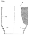
- the hose bellows 4 according to the invention shown in FIG. 1 has - as in Hose bellows common - no end beads on. This makes it possible Manufacture hose bellows as sections of an endless hose. While conventional tubular roller bellows are designed purely cylindrical, the hose bellows 4 according to the invention on its "lower", the rolling piston end facing an approximately conical taper (conical area, 32). The The taper is already in the untensioned, depressurized state. The upper" Area 18 of the tubular bellows 4 is - as with conventional tubular bellows - cylindrical.
- Fig. 2 shows the same hose bellows 4, but in the installed state, ie as part of an air spring 2.
- the bellows 4 is on a cover (cover plate) 8 and at its “lower” end on a rolling piston 6 attached pressure-tight with a clamping ring 12a, 12b.
- the tapering shape and the type of clamping on the unwinding piston 6 have the consequence that the hose bellows 4 already leaves the clamping point on the unwinding piston 6 almost at a right angle in the unpressurized state.
- “L zy1 " indicates the cylindrical region 18 of the hose bellows 4, while “L ü " means the axial length of the approximately conical region 32.
- D D denotes the diameter of the cylindrical region 18;
- D K is the diameter of the rolling piston 6.
- 30 denotes the wall thickness of the hose bellows 4.
- FIG. 3 shows the same basic structure of an air spring 2, consisting of cover plate 8, Rolling bellows 4 and rolling piston 6.
- the bellows 4 is correspondingly inflated to the outside (left side).
- the right side of FIG. 3 represents the compressed state of the pressurized air spring 2.
- the “upper” region 18 of the tubular bellows 4 is cylindrical (L cyl ).
- the cylindrical portion 18 of the approximately conical (transition) zone (L ü) 32 is followed by downward.
- the roller bellows 4 is clamped pressure-tight by means of a clamping ring on the (top) cover plate (cover) 8.
- the lower end of the hose bellows 4 is also attached pressure-tight and tensile to the rolling piston 6 by means of a clamping ring 12b.
- the rolling piston 6 has a circumferential recess (groove) 10 at its upper end.
- This depression 10 serves to receive the lower end of the hose bellows 4, on which the clamping ring 12b is placed and compressed on all sides.
- the circumferential recess (groove) 10 is delimited by a bead 14 which forms the upper edge of the rolling piston 6.
- the outer diameter 20 of the bead 14 corresponds approximately to the outer diameter 24 of the clamping ring 12b and also the rolling diameter (D K ) 22 of the piston 6.
Landscapes
- Engineering & Computer Science (AREA)
- General Engineering & Computer Science (AREA)
- Mechanical Engineering (AREA)
- Fluid-Damping Devices (AREA)
- Air-Flow Control Members (AREA)
- Fertilizers (AREA)
- Devices And Processes Conducted In The Presence Of Fluids And Solid Particles (AREA)
- Diaphragms And Bellows (AREA)
- Sealing Devices (AREA)
Abstract
Description
Die Erfindung geht aus von einer Schlauchrollbalg-Luftfeder nach der Gattung des Hauptanspruchs.The invention relates to a hose bellows air spring according to the genus Main claim.
Ein üblicher Schlauchrollbalg weist eine zylindrische Wandung auf, die axial an einem
Abrollkolben befestigt ist. Alle bekannten Schlauchrollbalg-Luftfeder-Typen funktionieren
ausschließlich im druckbeaufschlagten Zustand. Im drucklosen Zustand ist ein Abrollen
des Schlauchrollbalgs auf dem Abrollkolben nicht möglich.
Ein druckloser Zustand kann z. B. bei Wartungsarbeiten auftreten. Wird ein Fahrzeug auf
einer Hebebühne angehoben, werden die Luftfedern auseinandergezogen (vom
Fahrzeuggewicht entlastet und durch das Achsgewicht gezogen). Wird das Fahrzeug dann
mit drucklosen Luftfedern wieder abgesetzt, ergeben sich bei herkömmlichen
Schlauchrollbälgen unkontrollierbare Stauchungen, die von der Beschädigung bis hin zur
Zerstörung der Luftfeder führen.A conventional hose bellows has a cylindrical wall which is axially attached to a rolling piston. All known hose bellows air spring types work only when pressurized. In the depressurized state, it is not possible to roll the hose bellows on the roll-off piston.
A depressurized state can e.g. B. occur during maintenance work. If a vehicle is lifted on a lifting platform, the air springs are pulled apart (relieved of the vehicle weight and pulled by the axle weight). If the vehicle is then lowered again with pressureless air springs, uncontrollable compressions result in conventional hose rolling bellows, which result in damage to the destruction of the air spring.
In der EP 0 548 581 B1 wird eine gattungsgemäße Schlauchrollbalg-Luftfeder beschrieben, bei der die Rollbalg-Einspannung nicht - wie üblich - axial sondern radial ausgerichtet ist (siehe dort z. B. Fig. 1 und Fig. 4). Die radiale Ausrichtung der Rollbalg-Befestigung hat den Vorteil, dass für den Abrollvorgang lediglich nur eine 90°-Umlenkung erforderlich wird. Der quer zur Achse orientierte Austritt aus der Einspannung bedingt - allein betrachtet - noch keine Voraussetzung für ein druckloses Abrollen. Des weiteren betrachtet, stellt die EP 0 548 581 B1, Fig. 1, sehr treffend den Sachverhalt dar (drucklos: ausgezogene Linien; druckbeaufschlagt: gestrichelte Linien). Im drucklosen Zustand (ausgezogene Linien) ergibt sich ein scharfes Abknicken des radial aus der Befestigung austretenden Rollbalgs. Bei drucklosem Stauchen der Luftfeder ist ein einwandfreies Abrollen des Balgs auf der Kolbenwand nicht gewährleistet.EP 0 548 581 B1 describes a hose bellows air spring of the generic type, where the bellows clamping is not - as usual - aligned axially but radially (see for example Fig. 1 and Fig. 4). Has the radial alignment of the roll bellows attachment the advantage that only a 90 ° deflection is required for the rolling process becomes. The exit from the restraint oriented transversely to the axis causes - alone considered - not yet a prerequisite for unpressurized rolling. Furthermore considered, EP 0 548 581 B1, Fig. 1, aptly describes the facts (unpressurized: solid lines; pressurized: dashed lines). When depressurized (solid lines) there is a sharp bend in the radial from the attachment escaping roll bellows. When the air spring is compressed without pressure, it is perfect Rolling of the bellows on the piston wall is not guaranteed.
Die Aufgabe der Erfindung besteht darin, diesen - insbesondere im drucklosen Zustand gegebenen - Missstand auszuräumen. Auch im drucklosen Zustand soll ein einwandfreies Abrollen des Balges auf der Kolbenwand gewährleistet sein.The object of the invention is this - especially in the depressurized state given - to remedy maladministration. Even in a depressurized state, it should be flawless Rolling of the bellows on the piston wall must be guaranteed.
Wie aus Anspruch 1 ersichtlich, wird die gestellte Aufgabe im wesentlichen durch die
Verknüpfung zweier Merkmale gelöst, nämlich
Durch die erfindungsgemäße Verknüpfung dieser beiden Merkmale wird sichergestellt, dass die radiale Orientierung an der Befestigungsstelle auch im drucklosen Zustand gegeben ist, so dass der Balg nach beiden Seiten ungehindert umgelenkt werden kann.The combination of these two features according to the invention ensures that that the radial orientation at the attachment point even when depressurized is given, so that the bellows can be deflected freely on both sides.
Der Schlauchrollbalg weist zumindest an seinem Befestigungs-Ende eine - vorzugsweise konische - Verjüngung auf, wobei der Einspannbereich mit einem kleineren Durchmesser versehen ist, während der übrige Balgkörper einen größeren Durchmesser mit zylindrischer Gestalt aufweist. Aufgrund der besonderen Art der Einspannung am Abrollkolben-Ende beträgt die Umlenkung des Rollbalgs nur ca. 90°. Dabei entspricht der Außendurchmesser des am Kolben-Ende befindlichen Wulstes annähernd dem Abrolldurchmesser des Kolbens. Außerdem entspricht der Außendurchmesser des Wulstes annähernd dem Außendurchmesser des geklemmten Klemmringes. Die umlaufende Vertiefung (=Einspannbereich) und der Wulst sind so ausgebildet, dass bereits im drucklosen Zustand ein eindeutiger Durchmessersprung zwischen Einspanndurchmesser und übrigem Balgdurchmesser vorliegt.The hose bellows has a - preferably at least at its fastening end conical - tapering on, with the clamping area having a smaller diameter is provided, while the remaining bellows body has a larger diameter with a cylindrical Has shape. Due to the special type of clamping at the end of the rolling piston the bellows deflection is only approx. 90 °. The outer diameter corresponds to this of the bulge located at the piston end approximately the rolling diameter of the Piston. In addition, the outer diameter of the bead corresponds approximately to that Outside diameter of the clamped clamping ring. The circumferential deepening (= Clamping area) and the bead are designed so that they are already in a depressurized state a clear jump in diameter between the clamping diameter and the rest Bellows diameter is present.
Bei der praktischen Umsetzung der Erfindung haben sich die in den Unteransprüchen angegebenen Dimensionierungen als besonders vorteilhaft erwiesen:In the practical implementation of the invention have in the subclaims dimensions shown have proven to be particularly advantageous:
Die Durchmesser-Differenz von Rollbalg und Abrollkolben ist ungefähr gleich dem
Achtfachen der Wandstärke des Rollbalgs, wobei die Wandstärke des Rollbalgs ca 1,5 bis
6 mm beträgt, d. h.: DD- DK ≃ 12 bis 48 mm.
Der konische Bereich des Rollbalgs ist kleiner als die doppelte Durchmesser-Differenz
von Rollbalg und Abrollkolben, d. h.: Lü < 24 bis 96 mm.
Das Produkt aus Rollbalgdurchmesser und Rollbalg-Wandstärke ist größer als die
zylindrische Rollbalg-Länge, d. h.: LZyl < 1,5 DD bis 6 DD [mm].The diameter difference between the bellows and the rolling piston is approximately equal to eight times the wall thickness of the bellows, the wall thickness of the bellows being approximately 1.5 to 6 mm, ie: D D - D K ≃ 12 to 48 mm.
The conical area of the bellows is smaller than twice the difference in diameter between the bellows and the rolling piston, ie: Lü <24 to 96 mm.
The product of the roll bellows diameter and roll bellows wall thickness is larger than the cylindrical roll bellows length, ie: L cyl <1.5 D D to 6 D D [mm].
Verglichen mit dem genannten Stand der Technik wird mit der erfindungsgemäßen Luftfeder ein günstigeres Abrollverhalten insbesondere bei druckloser Luftfeder erzielt. Bei Kraftausübung auf den Abrollkolben ist ein druckloses Einfalten unter Beibehaltung eines kleinen Abrollradius möglich. Beim drucklosen Einrollen wird ein Einknicken des Balges vermieden.Compared with the prior art mentioned, the invention Air spring achieves a more favorable rolling behavior, especially when the air spring is depressurized. When force is exerted on the unwinding piston, pressure-free folding is maintained a small rolling radius possible. When rolling in without pressure, the Balges avoided.
Ein Ausführungsbeispiel der Erfindung ist in den Zeichnungen dargestellt und in der
nachfolgenden Beschreibung näher erläutert. Es zeigt:
Der in Fig. 1 dargestellte, erfindungsgemäße Schlauchrollbalg 4 weist - wie bei
Schlauchrollbälgen üblich - keine endseitigen Wülste auf. Dadurch ist es möglich,
Schlauchrollbälge als Abschnitte eines endlosen Schlauches herzustellen. Während
herkömmliche Schlauchrollbälge rein zylindrisch ausgebildet sind, weist der
erfindungsgemäße Schlauchrollbalg 4 an seinem "unteren", dem Abrollkolben
zugewandten Ende eine in etwa konische Verjüngung (konischer Bereich, 32) auf. Die
Verjüngung ist bereits im unverspannten, drucklosen Zustand gegeben. Der "obere"
Bereich 18 des Schlauchrollbalgs 4 ist - wie bei herkömmlichen Schlauchrollbälgen -
zylindrisch.The
Die Fig. 2 zeigt denselben Schlauchrollbalg 4, aber im eingebauten Zustand, d. h. als Teil
einer Luftfeder 2. An seinem "oberen" Ende ist der Balg 4 an einem Deckel (Abdeckplatte)
8 und an seinem "unteren" Ende an einem Abrollkolben 6 jeweils mit einem Klemmring
12a, 12b druckdicht befestigt. Die sich verjüngende Gestalt und die Art der Einspannung
am Abrollkolben 6 haben zur Folge, dass der Schlauchrollbalg 4 bereits im drucklosen
Zustand die Einspannstelle am Abrollkolben 6 quasi rechtwinklig verlässt.
"Lzy1" gibt den zylindrischen Bereich 18 des Schlauchrollbalges 4 an, während "Lü" die
axiale Länge des in etwa konischen Bereichs 32 bedeutet. Mit "DD" ist der Durchmesser
des zylindrischen Bereichs 18 bezeichnet; "DK" ist der Durchmesser des Abrollkolbens 6.
"30" bezeichnet die Wandstärke des Schlauchrollbalgs 4.Fig. 2 shows the
"L zy1 " indicates the
Die Fig. 3 zeigt denselben Grundaufbau einer Luftfeder 2, bestehend aus Abdeckplatte 8,
Rollbalg 4 und Abrollkolben 6. Durch eine Beaufschlagung der Luftfeder 2 mit Druckluft
ist der Rollbalg 4 entsprechend nach außen gebläht (linke Seite). Die rechte Seite der Fig. 3
stellt den eingefederten Zustand der druckbeaufschlagten Luftfeder 2 dar.3 shows the same basic structure of an
Aus der Fig. 4 gehen die beiden wesentlichen Details der Erfindung hervor, nämlich die
Verjüngung des "unteren" Rollbalgbereichs 32 und die Art der Einspannung des Rollbalgs
4 am Abrollkolben 6. 4 shows the two essential details of the invention, namely the
Tapering of the "lower" bellows
Wie bereits an der Fig. 1 erläutert, ist der "obere" Bereich 18 des Schlauchrollbalgs 4
zylindrisch ausgebildet (Lzyl). An den zylindrischen Bereich 18 schließt sich nach unten der
in etwa konische (Übergangs-) Bereich (Lü) 32 an. An seinem oberen Ende ist der Rollbalg
4 mittels eines Klemmringes an der (oben befindlichen) Abdeckplatte (Deckel) 8
druckdicht eingespannt.
Das unter Ende des Schlauchrollbalgs 4 ist mittels eines Klemmringes 12b am
Abrollkolben 6 ebenfalls druckdicht und zugfest angebracht. Zwecks Befestigung des
Schlauchrollbalgs 4 weist der Abrollkolben 6 an seinem oberen Ende eine umlaufende
Vertiefung (Nut) 10 auf.
Diese Vertiefung 10 dient zur Aufnahme des unteren Endes des Schlauchrollbalgs 4, auf
den der Klemmring 12b aufgesetzt und allseits zusammengedrückt wird.
Die umlaufende Vertiefung (Nut) 10 wird von einem Wulst 14 begrenzt, der den oberen
Rand des Abrollkolbens 6 bildet. Der Außendurchmesser 20 des Wulstes 14 entspricht
annähernd dem Außendurchmesser 24 des Klemmringes 12b und außerdem dem
Abrolldurchmesser (DK) 22 des Kolbens 6. Die umlaufende Vertiefung (=Einspannbereich)
10 und der Wulst 14 sind so ausgebildet, dass (bereits) im drucklosen Zustand ein
eindeutiger Durchmessersprung zwischen dem zylindrischen Durchmesser (DK) 28 des
zylindrischen Balgbereichs 18 und dem Durchmesser 26 im Spannbereich des Balges 4 am
Kolben 6 vorliegt, wodurch das mittels Klemmring 12b eingespannte Rollbalg-Ende um
90° abgelenkt wird und senkrecht (radial) nach außen gerichtet ist. As already explained in FIG. 1, the “upper”
The lower end of the hose bellows 4 is also attached pressure-tight and tensile to the
This
The circumferential recess (groove) 10 is delimited by a
- 22
- Luftfederair spring
- 44
- Schlauchrollbalg, RollbalgHose bellows, roller bellows
- 66
- Abrollkolbenroll-off
- 88th
- Abdeckplattecover
- 1010
- Vertiefung, Nut, EinspannbereichDeepening, groove, clamping area
- 12a, 12b12a, 12b
- Klemmringclamping ring
- 1414
- Wulstbead
- 1616
- (konische) Verjüngung des Rollbalgs(conical) tapering of the bellows
- 1818
- zylindrischer Bereich des Rollbalgs (LZyl)cylindrical area of the bellows (L cyl )
- 2020
- Außendurchmesser des WulstesOutside diameter of the bead
- 2222
- Abrolldurchmesser des Kolbens (DK)Rolling diameter of the piston (D K )
- 2424
- Außendurchmesser des KlemmringesOutside diameter of the clamping ring
- 2626
- Einspanndurchmesser des BalgsClamping diameter of the bellows
- 2828
- Balgdurchmesser im zylindrischen Bereich, übriger Balgdurchmesser (DD)Bellows diameter in the cylindrical area, other bellows diameter (D D )
- 3030
- Wandstärke des RollbalgsWall thickness of the bellows
- 3232
- konische Länge (konischer Bereich) des Rollbalgs (LÜ)tapered length (tapered area) of the bellows (L Ü )
Claims (5)
dadurch gekennzeichnet, dass die umlaufende Vertiefung (=Einspannbereich, 10) und der Wulst (14) so ausgebildet sind, dass im drucklosen Zustand ein eindeutiger Durchmessersprung zwischen Einspanndurchmesser (26) und übrigem Balgdurchmesser (DD, 28) vorliegt.Hose roll bellows air spring according to claim 1,
characterized in that the circumferential recess (= clamping area, 10) and the bead (14) are designed such that there is a clear jump in diameter between the clamping diameter (26) and the remaining bellows diameter (D D , 28) in the depressurized state.
dadurch gekennzeichnet, dass die Durchmesser-Differenz von Rollbalg (4) und Abrollkolben (6) ungefähr gleich dem Achtfachen der Wandstärke (30) des Rollbalgs (4) ist, wobei die Wandstärke (30) des Rollbalgs (4) ca. 1,5 bis 6 mm beträgt, d. h. DD- DK = 12 bis 48 mm. Airbag hose bellows according to claim 1 or 2,
characterized in that the diameter difference between the rolling bellows (4) and the rolling piston (6) is approximately equal to eight times the wall thickness (30) of the rolling bellows (4), the wall thickness (30) of the rolling bellows (4) being approximately 1.5 is up to 6 mm, ie D D - D K = 12 to 48 mm.
dadurch gekennzeichnet, dass der sich verjüngende Bereich (LÜ, 32) des Rollbalgs (4) kleiner als die doppelte Durchmesser-Differenz von Rollbalg (4) und Abrollkolben (6) ist, d. h.: LÜ < 24 bis 96 mm.Airbag hose bellows according to one of claims 1 to 3,
characterized in that the tapered area (L Ü , 32) of the rolling bellows (4) is smaller than twice the difference in diameter between the rolling bellows (4) and the rolling piston (6), ie: L Ü <24 to 96 mm.
dadurch gekennzeichnet, dass das Produkt aus Rollbalg-Durchmesser (DD, 28) und Rollbalgwandstärke (30) pro mm größer ist als die zylindrische Rollbalglänge (LZyl, 18), d. h.: LZyl < 1,5 DD bis 6 DD [mm].Hose roll bellows air spring according to one of claims 1 to 4,
characterized in that the product of the bellows diameter (D D , 28) and the bellows wall thickness (30) per mm is greater than the cylindrical roll bellows length (L cyl , 18), ie: L cyl <1.5 D D to 6 D D [mm].
Applications Claiming Priority (2)
| Application Number | Priority Date | Filing Date | Title |
|---|---|---|---|
| DE10216750A DE10216750A1 (en) | 2002-04-16 | 2002-04-16 | Rolling lobe air spring |
| DE10216750 | 2002-04-16 |
Publications (2)
| Publication Number | Publication Date |
|---|---|
| EP1355079A1 true EP1355079A1 (en) | 2003-10-22 |
| EP1355079B1 EP1355079B1 (en) | 2005-09-14 |
Family
ID=28458854
Family Applications (1)
| Application Number | Title | Priority Date | Filing Date |
|---|---|---|---|
| EP03002426A Expired - Lifetime EP1355079B1 (en) | 2002-04-16 | 2003-02-05 | Rolling lobe air spring |
Country Status (5)
| Country | Link |
|---|---|
| US (1) | US7226044B2 (en) |
| EP (1) | EP1355079B1 (en) |
| AT (1) | ATE304670T1 (en) |
| DE (2) | DE10216750A1 (en) |
| ES (1) | ES2248651T3 (en) |
Cited By (2)
| Publication number | Priority date | Publication date | Assignee | Title |
|---|---|---|---|---|
| DE10354574B3 (en) * | 2003-11-21 | 2005-01-27 | Contitech Luftfedersysteme Gmbh | Pneumatic spring with seamless hose roll bellows for suspension has fixing region with two trapezoid projections |
| EP2060832A2 (en) | 2007-11-16 | 2009-05-20 | Continental Aktiengesellschaft | Clamp contour for a pressure admittable component and tensioner therefor |
Families Citing this family (5)
| Publication number | Priority date | Publication date | Assignee | Title |
|---|---|---|---|---|
| DE102004054205A1 (en) * | 2004-11-10 | 2006-05-11 | Zf Friedrichshafen Ag | air spring |
| DE102005041800B3 (en) | 2005-09-02 | 2007-03-01 | Otto Sauer Achsenfabrik Gmbh | Air bellow for pneumatic spring, has axial sided area laid out so that area receives key according to complete aspect ratio of air bellow with movement of axial sided area to assembly sided area based on shape memory to roll over plunger |
| MX2012003257A (en) * | 2009-09-17 | 2012-06-19 | Firestone Ind Products Co Llc | Flexible sleeve, gas spring assembly and method. |
| MX2012004403A (en) * | 2009-10-14 | 2012-05-08 | Firestone Ind Products Co Llc | End member, gas spring assembly and method. |
| US8733743B2 (en) * | 2010-12-23 | 2014-05-27 | Firestone Industrial Products Company, Llc | Gas spring piston, gas spring assembly and method |
Citations (4)
| Publication number | Priority date | Publication date | Assignee | Title |
|---|---|---|---|---|
| DE2050613A1 (en) * | 1970-10-15 | 1972-04-20 | Continental Gummi Werke Ag | Air bag |
| EP0548581A1 (en) * | 1991-12-21 | 1993-06-30 | Continental Aktiengesellschaft | Air spring with a beadless air cushion made of elastomeric material |
| WO2000043692A1 (en) * | 1999-01-21 | 2000-07-27 | Phoenix Aktiengesellschaft | Pneumatic suspension system |
| EP1031756A2 (en) * | 1999-02-23 | 2000-08-30 | Bayerische Motoren Werke Aktiengesellschaft | Fastening of the rolling diaphragm of an air spring on a supporting member |
Family Cites Families (13)
| Publication number | Priority date | Publication date | Assignee | Title |
|---|---|---|---|---|
| JPS62167943A (en) * | 1986-01-21 | 1987-07-24 | Bridgestone Corp | Pneumatic spring |
| DE3643073A1 (en) * | 1986-12-17 | 1988-06-30 | Phoenix Ag | Pneumatic spring |
| US5005808A (en) * | 1987-12-01 | 1991-04-09 | The Goodyear Tire & Rubber Company | Airspring end member and airspring assembly |
| US4899995A (en) * | 1988-12-29 | 1990-02-13 | Bridgestone/Firestone, Inc. | Clamp ring assembly for air spring |
| US4946144A (en) * | 1989-03-30 | 1990-08-07 | Bridgestone/Firestone, Inc. | External clamping band for air spring |
| US5374037A (en) * | 1993-09-20 | 1994-12-20 | Bridgestone/Firestone, Inc. | Clamp ring assembly for air spring |
| US6439550B1 (en) * | 1997-02-18 | 2002-08-27 | Bfs Diversified Products, Llc | Adhesive laminate and method of securing a rubber air spring to a fixturing sleeve |
| ES2267493T3 (en) * | 1999-01-04 | 2007-03-16 | Otto Sauer Achsenfabrik Gmbh | VEHICLE SHAFT SUSPENSION. |
| JP2003503645A (en) * | 1999-06-11 | 2003-01-28 | ザ ゲイツ コーポレイション | Dual curved air spring |
| DE19959011A1 (en) * | 1999-12-08 | 2001-06-13 | Contitech Luftfedersyst Gmbh | Tight fastening of an air bellows |
| US6474630B1 (en) * | 2001-04-24 | 2002-11-05 | Bfs Diversified Products, Llc | Air spring swage assembly |
| DE10249741A1 (en) * | 2002-10-25 | 2004-05-06 | Continental Aktiengesellschaft | Bellows air spring with support bell |
| DE102004056517A1 (en) * | 2004-11-24 | 2006-06-01 | Contitech Luftfedersysteme Gmbh | Tiefbettklemmkontur for hose roll air springs |
-
2002
- 2002-04-16 DE DE10216750A patent/DE10216750A1/en not_active Withdrawn
-
2003
- 2003-02-05 ES ES03002426T patent/ES2248651T3/en not_active Expired - Lifetime
- 2003-02-05 DE DE50301165T patent/DE50301165D1/en not_active Expired - Lifetime
- 2003-02-05 AT AT03002426T patent/ATE304670T1/en not_active IP Right Cessation
- 2003-02-05 EP EP03002426A patent/EP1355079B1/en not_active Expired - Lifetime
- 2003-04-16 US US10/414,052 patent/US7226044B2/en not_active Expired - Lifetime
Patent Citations (4)
| Publication number | Priority date | Publication date | Assignee | Title |
|---|---|---|---|---|
| DE2050613A1 (en) * | 1970-10-15 | 1972-04-20 | Continental Gummi Werke Ag | Air bag |
| EP0548581A1 (en) * | 1991-12-21 | 1993-06-30 | Continental Aktiengesellschaft | Air spring with a beadless air cushion made of elastomeric material |
| WO2000043692A1 (en) * | 1999-01-21 | 2000-07-27 | Phoenix Aktiengesellschaft | Pneumatic suspension system |
| EP1031756A2 (en) * | 1999-02-23 | 2000-08-30 | Bayerische Motoren Werke Aktiengesellschaft | Fastening of the rolling diaphragm of an air spring on a supporting member |
Cited By (3)
| Publication number | Priority date | Publication date | Assignee | Title |
|---|---|---|---|---|
| DE10354574B3 (en) * | 2003-11-21 | 2005-01-27 | Contitech Luftfedersysteme Gmbh | Pneumatic spring with seamless hose roll bellows for suspension has fixing region with two trapezoid projections |
| EP2060832A2 (en) | 2007-11-16 | 2009-05-20 | Continental Aktiengesellschaft | Clamp contour for a pressure admittable component and tensioner therefor |
| DE102007055077A1 (en) | 2007-11-16 | 2009-05-20 | Continental Aktiengesellschaft | Clamping contour for a pressurizable component and clamping means therefor |
Also Published As
| Publication number | Publication date |
|---|---|
| DE50301165D1 (en) | 2005-10-20 |
| DE10216750A1 (en) | 2003-10-30 |
| US20050280193A1 (en) | 2005-12-22 |
| US7226044B2 (en) | 2007-06-05 |
| ES2248651T3 (en) | 2006-03-16 |
| ATE304670T1 (en) | 2005-09-15 |
| EP1355079B1 (en) | 2005-09-14 |
Similar Documents
| Publication | Publication Date | Title |
|---|---|---|
| DE2600748C2 (en) | Tire-rim arrangement | |
| DE60009719T2 (en) | DEFORMABLE DRIVE SHAFT AND STEERING COLUMN PRODUCED BY HIGH PRESSURE FORMERS AND METHOD OF MANUFACTURING THE SAME | |
| EP0151696A1 (en) | Pneumatic suspension, in particular for road vehicles | |
| EP1693233A1 (en) | Air spring strut with centrally positioned damper | |
| DE3147231C1 (en) | Air spring | |
| EP1140529B1 (en) | Vehicle axle suspension | |
| DE4135900C2 (en) | Air spring, in particular for motor vehicles | |
| DE69721969T2 (en) | Clamping device for pneumatic actuator | |
| EP2984364A1 (en) | Air spring, in particular for vehicles | |
| WO2013167390A1 (en) | Air spring and method for turning up an air spring bellows of an air spring | |
| DE19533479C2 (en) | Vehicle axle | |
| EP1355079A1 (en) | Rolling lobe air spring | |
| DE4006480A1 (en) | ROLL BELLOW AIR SPRING WITH A TUBULAR ROLL BELLOW MADE OF ELASTOMERIC MATERIAL | |
| WO2000043692A1 (en) | Pneumatic suspension system | |
| EP1321694A2 (en) | Tubular rolling lobe spring | |
| WO2018054600A1 (en) | Damping valve for a vibration damper | |
| EP2090801A1 (en) | Pneumatic spring rollIing bellows | |
| DE2845266C2 (en) | Safety parking brake for hydraulic lifts, lifting platforms and the like. | |
| DE19645228C2 (en) | Air spring with rolling body | |
| EP1321693A1 (en) | Double rolling lobe spring assembly | |
| DE102004015248A1 (en) | Lifting sleeve for a printing cylinder of an offset printing machine | |
| DE102011056338B4 (en) | Method for turning up a tire building part on a tire building drum for the production of green tires | |
| DE102004015602B4 (en) | Air spring device | |
| DE4438931C2 (en) | Hydro bearing | |
| WO2005024265A1 (en) | Method for fixing a pneumatic spring rolled bellows to a mounting |
Legal Events
| Date | Code | Title | Description |
|---|---|---|---|
| PUAI | Public reference made under article 153(3) epc to a published international application that has entered the european phase |
Free format text: ORIGINAL CODE: 0009012 |
|
| AK | Designated contracting states |
Kind code of ref document: A1 Designated state(s): AT BE BG CH CY CZ DE DK EE ES FI FR GB GR HU IE IT LI LU MC NL PT SE SI SK TR |
|
| AX | Request for extension of the european patent |
Extension state: AL LT LV MK RO |
|
| 17P | Request for examination filed |
Effective date: 20040422 |
|
| 17Q | First examination report despatched |
Effective date: 20040524 |
|
| AKX | Designation fees paid |
Designated state(s): AT BE BG CH CY CZ DE DK EE ES FI FR GB GR HU IE IT LI LU MC NL PT SE SI SK TR |
|
| GRAP | Despatch of communication of intention to grant a patent |
Free format text: ORIGINAL CODE: EPIDOSNIGR1 |
|
| GRAS | Grant fee paid |
Free format text: ORIGINAL CODE: EPIDOSNIGR3 |
|
| GRAA | (expected) grant |
Free format text: ORIGINAL CODE: 0009210 |
|
| AK | Designated contracting states |
Kind code of ref document: B1 Designated state(s): AT BE BG CH CY CZ DE DK EE ES FI FR GB GR HU IE IT LI LU MC NL PT SE SI SK TR |
|
| PG25 | Lapsed in a contracting state [announced via postgrant information from national office to epo] |
Ref country code: SK Free format text: LAPSE BECAUSE OF FAILURE TO SUBMIT A TRANSLATION OF THE DESCRIPTION OR TO PAY THE FEE WITHIN THE PRESCRIBED TIME-LIMIT Effective date: 20050914 Ref country code: FI Free format text: LAPSE BECAUSE OF FAILURE TO SUBMIT A TRANSLATION OF THE DESCRIPTION OR TO PAY THE FEE WITHIN THE PRESCRIBED TIME-LIMIT Effective date: 20050914 Ref country code: CZ Free format text: LAPSE BECAUSE OF FAILURE TO SUBMIT A TRANSLATION OF THE DESCRIPTION OR TO PAY THE FEE WITHIN THE PRESCRIBED TIME-LIMIT Effective date: 20050914 Ref country code: SI Free format text: LAPSE BECAUSE OF FAILURE TO SUBMIT A TRANSLATION OF THE DESCRIPTION OR TO PAY THE FEE WITHIN THE PRESCRIBED TIME-LIMIT Effective date: 20050914 |
|
| REG | Reference to a national code |
Ref country code: GB Ref legal event code: FG4D Free format text: NOT ENGLISH |
|
| REG | Reference to a national code |
Ref country code: CH Ref legal event code: EP |
|
| REG | Reference to a national code |
Ref country code: IE Ref legal event code: FG4D Free format text: LANGUAGE OF EP DOCUMENT: GERMAN |
|
| REF | Corresponds to: |
Ref document number: 50301165 Country of ref document: DE Date of ref document: 20051020 Kind code of ref document: P |
|
| PG25 | Lapsed in a contracting state [announced via postgrant information from national office to epo] |
Ref country code: DK Free format text: LAPSE BECAUSE OF FAILURE TO SUBMIT A TRANSLATION OF THE DESCRIPTION OR TO PAY THE FEE WITHIN THE PRESCRIBED TIME-LIMIT Effective date: 20051214 Ref country code: GR Free format text: LAPSE BECAUSE OF FAILURE TO SUBMIT A TRANSLATION OF THE DESCRIPTION OR TO PAY THE FEE WITHIN THE PRESCRIBED TIME-LIMIT Effective date: 20051214 Ref country code: BG Free format text: LAPSE BECAUSE OF FAILURE TO SUBMIT A TRANSLATION OF THE DESCRIPTION OR TO PAY THE FEE WITHIN THE PRESCRIBED TIME-LIMIT Effective date: 20051214 |
|
| REG | Reference to a national code |
Ref country code: SE Ref legal event code: TRGR |
|
| GBT | Gb: translation of ep patent filed (gb section 77(6)(a)/1977) |
Effective date: 20060107 |
|
| PG25 | Lapsed in a contracting state [announced via postgrant information from national office to epo] |
Ref country code: AT Free format text: LAPSE BECAUSE OF NON-PAYMENT OF DUE FEES Effective date: 20060205 |
|
| PG25 | Lapsed in a contracting state [announced via postgrant information from national office to epo] |
Ref country code: PT Free format text: LAPSE BECAUSE OF FAILURE TO SUBMIT A TRANSLATION OF THE DESCRIPTION OR TO PAY THE FEE WITHIN THE PRESCRIBED TIME-LIMIT Effective date: 20060214 |
|
| PG25 | Lapsed in a contracting state [announced via postgrant information from national office to epo] |
Ref country code: MC Free format text: LAPSE BECAUSE OF NON-PAYMENT OF DUE FEES Effective date: 20060228 Ref country code: BE Free format text: LAPSE BECAUSE OF NON-PAYMENT OF DUE FEES Effective date: 20060228 Ref country code: LU Free format text: LAPSE BECAUSE OF NON-PAYMENT OF DUE FEES Effective date: 20060228 |
|
| REG | Reference to a national code |
Ref country code: HU Ref legal event code: AG4A Ref document number: E000143 Country of ref document: HU |
|
| REG | Reference to a national code |
Ref country code: ES Ref legal event code: FG2A Ref document number: 2248651 Country of ref document: ES Kind code of ref document: T3 |
|
| ET | Fr: translation filed | ||
| PLBE | No opposition filed within time limit |
Free format text: ORIGINAL CODE: 0009261 |
|
| STAA | Information on the status of an ep patent application or granted ep patent |
Free format text: STATUS: NO OPPOSITION FILED WITHIN TIME LIMIT |
|
| 26N | No opposition filed |
Effective date: 20060615 |
|
| PG25 | Lapsed in a contracting state [announced via postgrant information from national office to epo] |
Ref country code: LI Free format text: LAPSE BECAUSE OF NON-PAYMENT OF DUE FEES Effective date: 20070228 Ref country code: CH Free format text: LAPSE BECAUSE OF NON-PAYMENT OF DUE FEES Effective date: 20070228 |
|
| REG | Reference to a national code |
Ref country code: CH Ref legal event code: PL |
|
| BERE | Be: lapsed |
Owner name: CONTITECH LUFTFEDERSYSTEME G.M.B.H. Effective date: 20060228 |
|
| PG25 | Lapsed in a contracting state [announced via postgrant information from national office to epo] |
Ref country code: EE Free format text: LAPSE BECAUSE OF FAILURE TO SUBMIT A TRANSLATION OF THE DESCRIPTION OR TO PAY THE FEE WITHIN THE PRESCRIBED TIME-LIMIT Effective date: 20050914 |
|
| PG25 | Lapsed in a contracting state [announced via postgrant information from national office to epo] |
Ref country code: CY Free format text: LAPSE BECAUSE OF FAILURE TO SUBMIT A TRANSLATION OF THE DESCRIPTION OR TO PAY THE FEE WITHIN THE PRESCRIBED TIME-LIMIT Effective date: 20050914 |
|
| PGFP | Annual fee paid to national office [announced via postgrant information from national office to epo] |
Ref country code: NL Payment date: 20150218 Year of fee payment: 13 |
|
| PGFP | Annual fee paid to national office [announced via postgrant information from national office to epo] |
Ref country code: ES Payment date: 20150225 Year of fee payment: 13 |
|
| REG | Reference to a national code |
Ref country code: FR Ref legal event code: PLFP Year of fee payment: 14 |
|
| REG | Reference to a national code |
Ref country code: NL Ref legal event code: MM Effective date: 20160301 |
|
| PG25 | Lapsed in a contracting state [announced via postgrant information from national office to epo] |
Ref country code: NL Free format text: LAPSE BECAUSE OF NON-PAYMENT OF DUE FEES Effective date: 20160301 |
|
| REG | Reference to a national code |
Ref country code: FR Ref legal event code: PLFP Year of fee payment: 15 |
|
| PG25 | Lapsed in a contracting state [announced via postgrant information from national office to epo] |
Ref country code: ES Free format text: LAPSE BECAUSE OF NON-PAYMENT OF DUE FEES Effective date: 20160206 |
|
| REG | Reference to a national code |
Ref country code: FR Ref legal event code: PLFP Year of fee payment: 16 |
|
| PGFP | Annual fee paid to national office [announced via postgrant information from national office to epo] |
Ref country code: IE Payment date: 20190222 Year of fee payment: 17 |
|
| PGFP | Annual fee paid to national office [announced via postgrant information from national office to epo] |
Ref country code: BE Payment date: 20190218 Year of fee payment: 9 Ref country code: HU Payment date: 20190213 Year of fee payment: 17 |
|
| REG | Reference to a national code |
Ref country code: SE Ref legal event code: EUG |
|
| PG25 | Lapsed in a contracting state [announced via postgrant information from national office to epo] |
Ref country code: SE Free format text: LAPSE BECAUSE OF NON-PAYMENT OF DUE FEES Effective date: 20200206 |
|
| PG25 | Lapsed in a contracting state [announced via postgrant information from national office to epo] |
Ref country code: HU Free format text: LAPSE BECAUSE OF NON-PAYMENT OF DUE FEES Effective date: 20200206 |
|
| PG25 | Lapsed in a contracting state [announced via postgrant information from national office to epo] |
Ref country code: IE Free format text: LAPSE BECAUSE OF NON-PAYMENT OF DUE FEES Effective date: 20200205 |
|
| PGFP | Annual fee paid to national office [announced via postgrant information from national office to epo] |
Ref country code: TR Payment date: 20210204 Year of fee payment: 19 |
|
| PG25 | Lapsed in a contracting state [announced via postgrant information from national office to epo] |
Ref country code: IT Free format text: LAPSE BECAUSE OF NON-PAYMENT OF DUE FEES Effective date: 20200205 |
|
| PGFP | Annual fee paid to national office [announced via postgrant information from national office to epo] |
Ref country code: GB Payment date: 20220223 Year of fee payment: 20 Ref country code: DE Payment date: 20220228 Year of fee payment: 20 |
|
| PGFP | Annual fee paid to national office [announced via postgrant information from national office to epo] |
Ref country code: FR Payment date: 20220216 Year of fee payment: 20 |
|
| REG | Reference to a national code |
Ref country code: DE Ref legal event code: R071 Ref document number: 50301165 Country of ref document: DE |
|
| REG | Reference to a national code |
Ref country code: GB Ref legal event code: PE20 Expiry date: 20230204 |
|
| PG25 | Lapsed in a contracting state [announced via postgrant information from national office to epo] |
Ref country code: GB Free format text: LAPSE BECAUSE OF EXPIRATION OF PROTECTION Effective date: 20230204 |