EP1355055A1 - Fuel injection nozzle of engine - Google Patents
Fuel injection nozzle of engine Download PDFInfo
- Publication number
- EP1355055A1 EP1355055A1 EP02715856A EP02715856A EP1355055A1 EP 1355055 A1 EP1355055 A1 EP 1355055A1 EP 02715856 A EP02715856 A EP 02715856A EP 02715856 A EP02715856 A EP 02715856A EP 1355055 A1 EP1355055 A1 EP 1355055A1
- Authority
- EP
- European Patent Office
- Prior art keywords
- fuel injection
- injection nozzle
- valve arm
- fuel
- valve
- Prior art date
- Legal status (The legal status is an assumption and is not a legal conclusion. Google has not performed a legal analysis and makes no representation as to the accuracy of the status listed.)
- Granted
Links
Images






Classifications
-
- F—MECHANICAL ENGINEERING; LIGHTING; HEATING; WEAPONS; BLASTING
- F02—COMBUSTION ENGINES; HOT-GAS OR COMBUSTION-PRODUCT ENGINE PLANTS
- F02M—SUPPLYING COMBUSTION ENGINES IN GENERAL WITH COMBUSTIBLE MIXTURES OR CONSTITUENTS THEREOF
- F02M61/00—Fuel-injectors not provided for in groups F02M39/00 - F02M57/00 or F02M67/00
- F02M61/14—Arrangements of injectors with respect to engines; Mounting of injectors
-
- F—MECHANICAL ENGINEERING; LIGHTING; HEATING; WEAPONS; BLASTING
- F01—MACHINES OR ENGINES IN GENERAL; ENGINE PLANTS IN GENERAL; STEAM ENGINES
- F01L—CYCLICALLY OPERATING VALVES FOR MACHINES OR ENGINES
- F01L1/00—Valve-gear or valve arrangements, e.g. lift-valve gear
- F01L1/12—Transmitting gear between valve drive and valve
- F01L1/18—Rocking arms or levers
-
- F—MECHANICAL ENGINEERING; LIGHTING; HEATING; WEAPONS; BLASTING
- F01—MACHINES OR ENGINES IN GENERAL; ENGINE PLANTS IN GENERAL; STEAM ENGINES
- F01L—CYCLICALLY OPERATING VALVES FOR MACHINES OR ENGINES
- F01L1/00—Valve-gear or valve arrangements, e.g. lift-valve gear
- F01L1/20—Adjusting or compensating clearance
- F01L1/22—Adjusting or compensating clearance automatically, e.g. mechanically
- F01L1/24—Adjusting or compensating clearance automatically, e.g. mechanically by fluid means, e.g. hydraulically
-
- F—MECHANICAL ENGINEERING; LIGHTING; HEATING; WEAPONS; BLASTING
- F02—COMBUSTION ENGINES; HOT-GAS OR COMBUSTION-PRODUCT ENGINE PLANTS
- F02F—CYLINDERS, PISTONS OR CASINGS, FOR COMBUSTION ENGINES; ARRANGEMENTS OF SEALINGS IN COMBUSTION ENGINES
- F02F1/00—Cylinders; Cylinder heads
- F02F1/24—Cylinder heads
- F02F1/26—Cylinder heads having cooling means
- F02F1/36—Cylinder heads having cooling means for liquid cooling
- F02F1/38—Cylinder heads having cooling means for liquid cooling the cylinder heads being of overhead valve type
-
- F—MECHANICAL ENGINEERING; LIGHTING; HEATING; WEAPONS; BLASTING
- F02—COMBUSTION ENGINES; HOT-GAS OR COMBUSTION-PRODUCT ENGINE PLANTS
- F02F—CYLINDERS, PISTONS OR CASINGS, FOR COMBUSTION ENGINES; ARRANGEMENTS OF SEALINGS IN COMBUSTION ENGINES
- F02F1/00—Cylinders; Cylinder heads
- F02F1/24—Cylinder heads
- F02F1/42—Shape or arrangement of intake or exhaust channels in cylinder heads
- F02F1/4214—Shape or arrangement of intake or exhaust channels in cylinder heads specially adapted for four or more valves per cylinder
-
- F—MECHANICAL ENGINEERING; LIGHTING; HEATING; WEAPONS; BLASTING
- F02—COMBUSTION ENGINES; HOT-GAS OR COMBUSTION-PRODUCT ENGINE PLANTS
- F02F—CYLINDERS, PISTONS OR CASINGS, FOR COMBUSTION ENGINES; ARRANGEMENTS OF SEALINGS IN COMBUSTION ENGINES
- F02F7/00—Casings, e.g. crankcases
- F02F7/006—Camshaft or pushrod housings
-
- F—MECHANICAL ENGINEERING; LIGHTING; HEATING; WEAPONS; BLASTING
- F02—COMBUSTION ENGINES; HOT-GAS OR COMBUSTION-PRODUCT ENGINE PLANTS
- F02M—SUPPLYING COMBUSTION ENGINES IN GENERAL WITH COMBUSTIBLE MIXTURES OR CONSTITUENTS THEREOF
- F02M55/00—Fuel-injection apparatus characterised by their fuel conduits or their venting means; Arrangements of conduits between fuel tank and pump F02M37/00
- F02M55/002—Arrangement of leakage or drain conduits in or from injectors
-
- F—MECHANICAL ENGINEERING; LIGHTING; HEATING; WEAPONS; BLASTING
- F02—COMBUSTION ENGINES; HOT-GAS OR COMBUSTION-PRODUCT ENGINE PLANTS
- F02M—SUPPLYING COMBUSTION ENGINES IN GENERAL WITH COMBUSTIBLE MIXTURES OR CONSTITUENTS THEREOF
- F02M55/00—Fuel-injection apparatus characterised by their fuel conduits or their venting means; Arrangements of conduits between fuel tank and pump F02M37/00
- F02M55/02—Conduits between injection pumps and injectors, e.g. conduits between pump and common-rail or conduits between common-rail and injectors
-
- F—MECHANICAL ENGINEERING; LIGHTING; HEATING; WEAPONS; BLASTING
- F02—COMBUSTION ENGINES; HOT-GAS OR COMBUSTION-PRODUCT ENGINE PLANTS
- F02B—INTERNAL-COMBUSTION PISTON ENGINES; COMBUSTION ENGINES IN GENERAL
- F02B2275/00—Other engines, components or details, not provided for in other groups of this subclass
- F02B2275/10—Diamond configuration of valves in cylinder heads
-
- F—MECHANICAL ENGINEERING; LIGHTING; HEATING; WEAPONS; BLASTING
- F02—COMBUSTION ENGINES; HOT-GAS OR COMBUSTION-PRODUCT ENGINE PLANTS
- F02B—INTERNAL-COMBUSTION PISTON ENGINES; COMBUSTION ENGINES IN GENERAL
- F02B2275/00—Other engines, components or details, not provided for in other groups of this subclass
- F02B2275/14—Direct injection into combustion chamber
-
- F—MECHANICAL ENGINEERING; LIGHTING; HEATING; WEAPONS; BLASTING
- F02—COMBUSTION ENGINES; HOT-GAS OR COMBUSTION-PRODUCT ENGINE PLANTS
- F02B—INTERNAL-COMBUSTION PISTON ENGINES; COMBUSTION ENGINES IN GENERAL
- F02B2275/00—Other engines, components or details, not provided for in other groups of this subclass
- F02B2275/34—Lateral camshaft position
-
- F—MECHANICAL ENGINEERING; LIGHTING; HEATING; WEAPONS; BLASTING
- F02—COMBUSTION ENGINES; HOT-GAS OR COMBUSTION-PRODUCT ENGINE PLANTS
- F02B—INTERNAL-COMBUSTION PISTON ENGINES; COMBUSTION ENGINES IN GENERAL
- F02B3/00—Engines characterised by air compression and subsequent fuel addition
- F02B3/06—Engines characterised by air compression and subsequent fuel addition with compression ignition
-
- F—MECHANICAL ENGINEERING; LIGHTING; HEATING; WEAPONS; BLASTING
- F02—COMBUSTION ENGINES; HOT-GAS OR COMBUSTION-PRODUCT ENGINE PLANTS
- F02F—CYLINDERS, PISTONS OR CASINGS, FOR COMBUSTION ENGINES; ARRANGEMENTS OF SEALINGS IN COMBUSTION ENGINES
- F02F1/00—Cylinders; Cylinder heads
- F02F1/24—Cylinder heads
- F02F2001/244—Arrangement of valve stems in cylinder heads
- F02F2001/247—Arrangement of valve stems in cylinder heads the valve stems being orientated in parallel with the cylinder axis
-
- Y—GENERAL TAGGING OF NEW TECHNOLOGICAL DEVELOPMENTS; GENERAL TAGGING OF CROSS-SECTIONAL TECHNOLOGIES SPANNING OVER SEVERAL SECTIONS OF THE IPC; TECHNICAL SUBJECTS COVERED BY FORMER USPC CROSS-REFERENCE ART COLLECTIONS [XRACs] AND DIGESTS
- Y02—TECHNOLOGIES OR APPLICATIONS FOR MITIGATION OR ADAPTATION AGAINST CLIMATE CHANGE
- Y02T—CLIMATE CHANGE MITIGATION TECHNOLOGIES RELATED TO TRANSPORTATION
- Y02T10/00—Road transport of goods or passengers
- Y02T10/10—Internal combustion engine [ICE] based vehicles
- Y02T10/12—Improving ICE efficiencies
Definitions
- the present invention relates to a structure of a fuel injection nozzle attached into a cylinder head of an engine.
- a fuel injection valve is (fuel injection valves are) inserted downward into a cylinder head.
- a fuel injection nozzle retainer which may be made of a block member, axially presses the fuel injection nozzle and fixes it into the cylinder head.
- the fuel injection nozzle retainer is fastened at left and right ends thereof to the cylinder head by bolts.
- a holder is fastened at left and right ends thereof to a cylinder head by bolts so as to axially press a fuel injection nozzle, thereby locating and fixing it at an appointed place in the cylinder block.
- a fixture is fastened to a cylinder block by bolts so as to fix a fuel injection nozzle into the cylinder block.
- a conventional engine constructed in this way is so laterally elongated (in the longish direction of its cylinder head) as to appropriate for a fuel injection nozzle retainer which is fastened at left and right ends thereof to the cylinder head by bolts.
- a fuel injection nozzle retainer which is fastened at left and right ends thereof to the cylinder head by bolts.
- the fuel injection nozzle is necessarily arranged in the valve arm room because it requires to be substantially vertically inserted into the cylinder head at the substantially middle portion between inlet and exhaust valves.
- the fuel injection nozzle retainer for pressing down the fuel injection nozzle is supported at one end thereof on a vale arm shaft, thereby being arranged in the limited inner space of the valve arm room.
- the valve arm shaft supports the inlet valve, and on the other side, the valve arm shaft supports the exhaust valve.
- a retainer is extended from the fuel injection nozzle to the valve arm shaft so as to press down and fix the fuel injection nozzle.
- valve arm shaft is fittingly provided thereon with inlet and exhaust valve arms 37 on axially opposite sides thereof with respect to the retainer.
- valve arms for inlet valves and exhaust valves must be prepared in various forms corresponding to variation of cylinder boa pitches of engines, thereby increasing costs.
- a fuel pipe is inserted from outside into the valve arm room and connected top the fuel injection nozzle so as to supply the fuel injection nozzle with pressured fuel.
- the fuel pipe comprises an inner pipe arranged in the valve arm room formed in the valve arm casing, and outer pipe arranged outside the valve arm casing.
- a pipe joint including a high-pressured seal member is screwed into a side surface of the valve arm casing so as to connect the inner pipe and the outer pipe therethrough.
- a fuel back pipe extends outward from the valve arm casing through another pipe joint screwed into a side surface of the valve arm casing.
- the valve arm casing is necessarily bored so as to form female screws for the respective pipe joints for conducting the fuel pipe and the fuel back pipe, thereby increasing the number of manufacturing processes and parts.
- a fuel injection nozzle of an engine is fixed into a cylinder head by a fuel injection nozzle retainer supported by a support shaft which also supports valve arms and an energizing member for axially energizing the fuel injection nozzle retainer.
- the fuel injection nozzle retainer disposed on the support shaft does not shake, thereby facilitating location of the valve arm casing on the cylinder head.
- the power of the energizing member enables locating the flue injection nozzle retainer at the appointed place in axial direction.
- an interval between the inlet valve arm and the exhaust valve arm is adjustable by the fuel injection nozzle retainer and the energizing member, while the inlet valve arm is arranged on one side of the fuel injection nozzle retainer and the exhaust valve arm is arranged on the other side of the fuel injection nozzle retainer.
- a common valve arm can be used among various engines having different cylinder boa pitches.
- a fuel injection nozzle of an engine is fixed into a cylinder head by a fuel injection nozzle retainer, which straddles a head bolt fastening the cylinder head onto a cylinder block and is joined to the cylinder head.
- the fuel injection nozzle retainer directly contacts with the cylinder head without interfering with the head bolt so as to be surely fixed in the cylinder head, while saving a space for mounting the fuel injection nozzle retainer, and while saving costs for an additional member for supporting the fuel injection nozzle retainer.
- the fuel injection nozzle retainer is economically made of a metal plate by simple processes such as forming in the metal thin plate with holes for retaining the valves, a dent for straddling the head bolt, and holes for fixation.
- a fuel injection nozzle of an engine is fixed into a cylinder head by a fuel injection nozzle retainer, which is supported at one end thereof by a head bolt fastening the cylinder head onto a cylinder block.
- the fuel injection nozzle retainer is economically made of a metal plate by simple processes such as forming in the metal thin plate with holes for retaining the valves, a projecting portion, and holes for fixation.
- a projection formed on an end of the fuel injection nozzle retainer is fit into a dented top of the head bolt.
- the fuel injection nozzle retainer is stably fixed on the cylinder head without slipping relative to the cylinder head, thereby enabling sure settling the fuel injection nozzle.
- a fuel injection nozzle of an engine is supplied with fuel through a fuel pipe which penetrates a valve arm casing arranged above a cylinder head and containing valve arms and the fuel injection nozzle.
- a pipe joint is unnecessary to be screwed into a side surface portion of the valve arm casing so as to connect a fuel pipe outside the valve arm room to a fuel pipe in the valve arm room, thereby reducing the number of parts to be attached to the valve arm casing.
- valve arm casing is unnecessary to be formed with a female screw casing, thereby being simplified in shape and reduced in cost.
- a fuel pipe comprises the outer fuel pipe and the inner fuel pipe connected to each other through a high-pressured seal member, which ensures seal of this connection in the fuel pipe by itself so as to enhance the reliability over fuel leak.
- valve arm casing is provided at a portion thereof penetrated by the fuel pipe with a seal member for sealing the fuel pipe and with a notch applied for making a gap between the seal member and the penetrated portion of vale arm casing.
- a tool may be previously inserted into the notch so as to slightly pry out the high-pressured seal member before removing it, thereby enhancing efficiency of the removing work.
- a valve arm room of an engine, having a fuel injection nozzle retainer for fixing the fuel injection nozzle into the cylinder head according to the present invention will be described.
- a valve arm casing 2 is arranged above a cylinder head 1 of an engine so as to constitute a valve room 5.
- the valve arm casing 2 is composed of an upper valve arm casing 2b and a lower valve arm casing 2a.
- the 4-valve type engine has three cylinders, wherein each cylinder has two inlet valves and two exhaust valves.
- the engine is of the OHV type.
- the valve arm room 5 In the valve arm room 5 are disposed upper ends of pairs of inlet valves 16a and pairs of exhaust valves 16b, upper ends of push rods 13, valve arms 14, fuel injection nozzles 17, and so on.
- the valve arms 14 are rotatably supported on a valve arm shaft 11 in the valve arm room 5.
- valve arms 14 are provided to each pair of inlet valves 16a and to each pair of exhaust valves 16b, respectively. Each of the valve arms 14 is swung by vertically moving the corresponding push rod 13 so as to open and shut the inlet valves 16a, 16a or the exhaust valves 16b, 16b, respectively.
- each of the fuel injection nozzles 17 is arranged at the substantially center between each pair of inlet valves 16a and each pair of exhaust valves 16b, and inserted into the cylinder head 1 in the substantially vertical direction.
- Fuel injection nozzle retainers 15 press down the respective fuel injection nozzles 17 so as to locate them at appointed places in the vertical direction.
- Each of the fuel injection nozzle retainers 15 is rotatably supported on the valve arm shaft 11, and arranged between the valve arm 14 of the pair of inlet valves 16a and the valve arm 14 of the pair of exhaust valves 16b.
- Fuel pipes 21 are led into the valve arm room 5 from the outside and connected to the respective fuel injection nozzles 17 so as supply them with high-pressured fuel.
- Each of the fuel pipes 21 comprises an inner fuel pipe 21a, which is arranged in the valve arm room 5, and an outer fuel pipe 21b, which is arranged outside the valve arm room 5.
- the inner pipe 21a and the outer pipe 21b are connected to each other through a high-pressured seal member 22 in a side surface of the lower valve arm casing 2a.
- the fuel injection nozzles 17 provided to the respective cylinders are mutually connected by a fuel back pipe 23 so as to return excessive fuel therefrom through the fuel back pipe 23 and an outer fuel back pipe 24 to a fuel tank.
- Fuel pipe holes 2d are formed in the side surface of the lower valve arm casing 2a, and the fuel pipes 21 pass through the respective fuel pipe hole 2d.
- the high-pressure seal members 22 are removably fit in the respective fuel pipe holes 2d.
- the fuel pipe holes 2d formed through the side surface of the lower valve arm casing 2a for passing the respective fuel pipes 21 make it unnecessary to screw pipe joints into the side surface of the lower valve arm casing 2a so as to connect the inner fuel pipes 21a to the respective outer fuel pipes 21b, thereby reducing the number of parts attached to the lower valve arm casing 2a.
- the fuel pipe holes 2d save a process for making female screws within the lower valve arm casing 2a so as to simplify the shape of the lower valve arm casing 2a and to reduce the number of processes.
- each of the fuel pipes 21 is sealed at the joint portion thereof between the inner fuel pipe 21a and the outer fuel pipe 21b with the high-pressured seal member 22 so as to enhance the reliability thereof over fuel leak.
- valve arm shaft supporters 7 for supporting the valve arm shaft 11 are fixed on the top surface of cylinder head 1.
- the valve arm shaft 11 is supported by the valve arm shaft supporters 7 and the side surfaces of lower valve arm casings 2a.
- Bolts 31 are screwed downward into the respective valve arm shaft supporters 7 and exposed at heads thereof above the valve arm shaft supporters 7.
- Each of the valve arm shaft supporters 7 is, for example, arranged at each gap between neighboring cylinders.
- the upper valve arm casing 2b is bored with fixation holes 2c at points corresponding to the respective valve arm shaft supporters 7. Retaining nuts 32 are downwardly inserted into the respective fixation holes 2c from the outside above the upper valve arm casing 2b so as to be screwed around the respective upper portions of bolts 31.
- a flange 32a of the retaining nut 32 which is fit on the peripheral edge of the fixation hole 2c, presses down the lower valve arm casing 2b, thereby fixing the upper valve arm casing 2b onto the cylinder head 1 together with the lower valve arm casing 2a arranged below the upper valve arm casing 2b.
- the lower valve arm casing 2a is fixed onto the cylinder head 1 through the upper valve arm casing 2b which is pressed down by the retaining nuts 32 tightly fastened on the respective bolts 31.
- valve arm room 5 which has been enclosed with the upper and lower valve arm casings 2b and 2a, is upwardly opened so as to facilitate adjustment of clearance and maintenance about the inlet and exhaust valves 16a and 16b therein.
- a gasket 55 is disposed between the cylinder head 1 and the lower valve arm casing 2a so as to seal the joint surface therebetween.
- the lower valve arm casing 2a is formed at opposite side surfaces thereof into support portions 2e for supporting the valve arm shaft 11.
- the valve arm shaft 11 is supported at both ends thereof by the respective support portions 2e, and at intermediate portions thereof by the valve arm shaft supporters 7 fixed on the top surface of the cylinder head 1 in the valve arm room 5.
- the lower valve arm casing 2a is assembled together with the valve arm shaft 11 which is provided thereon with the valve arms 14, the fuel injection nozzle retainers 15 and the valve arm shaft supporters 7 and supported by the supporting portions 2e. Then, the assembly of the lower valve arm casing 2a is fixed onto the cylinder head 1, thereby reducing the total number of processes and improving the facility for assembly. Additionally, the number of valve arm shaft supporters 7 to be fixed to the cylinder head 1 can be reduced so as to reduce the total number of parts.
- valve arm casing 2 may be constituted as follows.
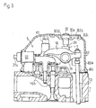
- a valve arm casing 82 as shown in Fig. 3, comprises a casing body 82a, which is provided at the top surface thereof with an opening 82c, and a cap 82b for covering the opening 82c.
- the cap 82b is bored with holes for fixation 82d at points corresponding to the valve arm shaft supporters 7.
- the retaining nuts 32 are inserted into the respective holes 82d from the outside above the caps 82b.
- the casing body 82a is fixed onto the cylinder head 1 through the cap 82b which is pressed down by the retaining nuts 32 tightly fastened on the respective bolts 31.
- the pair of valve arms 14 one for opening and shutting the pair of inlet valves 16a; and the other for opening and shutting the pair of exhaust valves 16b, are arranged between the valve arm shaft supporters 7.
- the fuel injection nozzle retainer 15 is arranged between the pair of valve arms 14 for inlet and exhaust valves 16a and 16b.
- An energizing member 35 such as a wave washer, is fit on the valve arm shaft 11 between the support member 7 and each of the valve arms 14. The valve arms 14 are pressed against the fuel injection nozzle retainer 15 by the respective energizing members 35.
- a distance dx between the neighboring valve arm shaft supporters 7 is slightly longer than the total widths of the pair of valve arms 14 for inlet and exhaust valves 16a and 16b and the fuel injection nozzle retainer 15 so as to make a margin for facilitating attachment of the valve arms 14 and the fuel injection nozzle retainer 15.
- the energizing member 35 serving as a spacer is provided in a gap between the valve arm shaft supporter 7 and the valve arm 14 so as to fill up the gap.
- a distance dp between the pair of valve arm 14: one for the pair of inlet valves 16a and the other for the pair of exhaust valves 16b, is determined corresponding to an interval da between the pair of inlet valves 16a and the pair of exhaust valves 16b.
- valve arm shaft 11 also serves as a support member for supporting the fuel injection nozzle retainers 15 so that the fuel injection nozzle retainers 15 may be supported by the lower valve arm casing 2a without providing an additional support member in the valve arm room 5 for supporting the fuel injection nozzle retainers 15, thereby reducing the number of parts and saving a space for arranging the fuel injection nozzle retainers 15.
- the fuel injection nozzle retainer 15 which is supported by the valve arm shaft 11 is a thin plate member, as shown in Fig. 5, which is bent at both ends thereof so as to form supporting portions 15a.
- a remaining flat portion 15b of the thin plate member serving as the fuel injection nozzle retainer 15 is bored by holes 15c for retaining the fuel injection nozzle 17 and holes 15d for fixing the fuel injection nozzle retainer 15.
- the energizing members 35 energize the respective valve arms 14 toward the fuel injection nozzle retainer 15 so that the fuel injection nozzle 15 is pressed by the valve arms 14 in opposite directions. Namely, the energizing members 35 indirectly energize the fuel injection nozzle retainer 15 so as to generate a friction force between the fuel injection nozzle retainer 15 and each of the valve arms 14, thereby restricting rotation of the fuel injection nozzle retainer 15.
- the postures of fuel injection nozzle retainers 15 fit on the valve arm shaft 11 can be held so as to facilitate location of the fuel injection nozzle retainers 15, thereby improving the facility of assembly.
- Fig. 6 shows a mounting portion of the valve arms 14 in an engine whose cylinder boa pitch is shorter than that of the engine of Fig. 4.
- a distance dy between the valve arm shaft supporters 7 of Fig. 6 is shorter than the corresponding distance dx of Fig. 4.
- An interval db between the pair of inlet valves 16a and the pair of exhaust valves 16b is shorter than the corresponding interval da of Fig. 4.
- a width dq of a portion for supporting a fuel injection nozzle retainer 45 of Fig. 6 is shorter than the width dp of the portion for supporting the fuel injection nozzle retainer 15 of Fig. 4 so as to make the total width of the pair of valve arms 14 and the fuel injection nozzle retainer 45 of Fig. 6 shorter than the corresponding width dy.
- An energizing member 35 is interposed between each of the valve arms 14 and the fuel injection nozzle retainer 45 so as to energize the valve arms 14 toward the valve arm shaft supporter 7.
- the interval db between the pair of inlet valves 16a and the pair of exhaust valves 16b is different from the corresponding interval da.
- the width dq of fuel injection nozzle retainer 45 is adjusted and the energizing members 35 are provided so that the interval between the valve arm 14 for the pair of inlet valves 16a and the valve arm 14 for the pair of exhaust valves 16b may coincide with the interval db.
- the interval between the pair of valve arms 14 may be adjusted correspondingly.
- the present valve arm room 5 is so constructed that the fuel injection nozzle retainers 15 and 45 having different widths are prepared and positions of the energizing members 35 fit on the valve arm shaft 11 supporting the fuel injection nozzle retainers 15 or 45 are changed so as to adjust each interval between the pair of valve arms 14 for the inlet and exhaust valves 16a and 16b to a value corresponding either the interval da or db.
- it is able to use the common valve arms 14 in spite of difference of cylinder boa pitch.
- the fuel injection nozzle retainers 15 and 45 are made of inexpensive sheet metal. Changing the form of fuel injection nozzle retainers so as to prepare the different shaped fuel injection nozzle retainers 15 and 45 without changing the valve arms 14 made by casting can save costs for adjusting the intervals among the valve arms 14 in comparison with changing the form of valve arms 14.
- the gasket 55 is formed with inwardly extending portions 55a corresponding to the respective push rods 13.
- a guide hole 55b applied for passing the push rod 13 therethrough.
- the gasket 55 is placed on the cylinder head 1 and the push rods 13 are passed through the respective guide holes 55b.
- top ends of push rods 13 are guided by guide holes 55b so as to be fixed in location without tottering, thereby facilitating location of the valve arms 14 relative to the respective top ends of the push rods 13 and facilitating fitting of the valve arms 14.
- the gasket 55 inherently interposed between the cylinder head 1 and lower valve arm casing 2a is used so as to save costs for guiding the push rods 13.
- a notch 2f is formed on the outer edge of each fuel pipe hole 2d in which the high-pressure seal member 22 is fit.
- the present lower valve arm casing 2a is formed with the notches 2f formed on the respective outer ends of fuel pipe holes 2d so as to facilitate for removing the high-pressure seal members 22.
- a tool may be previously inserted into the notch 2f so as to slightly pry out the high-pressure seal member 22 before removing it, thereby enhancing efficiency of the removing work.
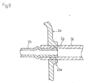
- the fuel back pipe 23 is extended to the outside of the valve arm casing 2a through the fuel back hole 2g formed in the side surface portion of lower valve arm casing 2a.
- fuel back pipe 23 is connected to the outer fuel back pipe 24, and passes with the outer fuel back pipe 24 through the fuel back hole 2g.
- the fuel back pipe 23 is composed of a steel tube or so on, and the outer fuel back pipe 24 is an elastic hose-like member made of rubber, synthetic risen or so on.
- the outer fuel back pipe 24 is compressed and interposed between the fuel back hole 2g and the fuel back pipe 23 penetrating the fuel back hole 2g so as to be connected to the outer fuel back pipe 24 and to seal the gap between the fuel back pipe 23 and the fuel back hole 2g.
- the outer fuel pipe 24, which is connected to the fuel back pipe 23 in the fuel back hole 2g, is a hose member for guiding excessive fuel from the fuel back pipe 23 outward from the valve arm room 5, and also serves as a seal member for sealing the space between the fuel back pipe 23 and the fuel back hole 2g.
- a piping comprising the fuel back pipe 23 and the outer fuel back pipe 24 for returning surplus fuel penetrates the side surface of the lower valve arm casing 2a through the fuel back hole 2g.
- Annular projections 23a are formed on the periphery of the fuel back pipe 23 in the fuel back hole 2g so as to prevent the fuel back pipe 23 from slipping out of the outer fuel back pipe 24.
- the fuel back pipe 23 for returning surplus fuel outward from the fuel injection nozzles 17 penetrates the side surface of the lower valve casing 2a through the outer fuel back pipe 24 serving as a seal member so as to require no pipe joint screwed into the side surface of the lower valve arm casing 2a, thereby reducing the number of parts attached to the lower valve arm casing 2a.
- the lower valve arm casing 2a requiring no process for making a female screw is formed simply so as to reduce the number of processes.
- the outer fuel pipe 24 connected to the fuel back pipe 23 serves as a seal member so as to enhance the reliability over fuel leak from the junction between the fuel back pipe 23 and the outer fuel back pipe 24.
- each cylinder has one inlet valve and one exhaust valve.
- a valve arm casing 52 is disposed on a cylinder head 51, and a valve arm room is constructed in the valve arm casing 52.
- Fuel injection nozzles 67 provided to respective cylinders are arranged out of the valve arm casing 52, and inserted into the cylinder head 51 through a top surface portion of cylinder head 51, which is not covered with the valve arm casing 52.
- Fuel injection nozzle retainers 65 press down the respective fuel injection nozzles 67 to appointed places in the vertical direction so as to fix them in the cylinder head 51.
- the fuel injection nozzle retainer 65 is formed on a first end portion thereof with a notch 65b and a pair of legs 65c on both sides of the notch 65b.
- the fuel injection nozzle retainer 65 is bored at the substantially center portion thereof with a fixation hole 65d for its fixation to the cylinder head 51.
- the fuel injection nozzle retainer 65 is formed on an opposite second end portion thereof with a nozzle retaining hole 65a for pressing down the fuel injection nozzle 67.
- Each of the fuel injection nozzles 67 is upwardly inserted at the top portion thereof into the nozzle retaining hole 65a of each fuel injection nozzle retainer 65.
- a bolt 39 is downwardly inserted into the fixation hole 65d of each fuel injection nozzle retainer 65 and screwed into the cylinder head 51 so as to press down the second end portion of fuel injection nozzle retainer 65 while the pair of legs 65c abutting against the top surface of cylinder head 51 1 function as a fulcrum. Therefore, a fitting portion 67a of the fuel injection nozzle 67 comes to fit the peripheral edge of the nozzle retaining hole 65a so that the fuel injection nozzle 67 pressed substantially downward by the fuel injection nozzle retainer 65 is fixed in the cylinder head 51.
- the head bolts 38 for fastening the cylinder head 51 onto the cylinder block are located below the respective first end portions of fuel injection nozzle retainers 65, the notches 65b of fuel injection nozzle retainers 65 are located corresponding to the respective head bolts 38 so as to prevent the fuel injection nozzle retainers 65 from contacting with the head bolts 38.
- each fuel injection nozzle retainer 65 straddles the head bolt 38 without abutting against the head bolt 38 so as to be fixed to the cylinder head 51.
- the fuel injection nozzle retainer 65 is made of a thin plate, in which the nozzle retaining hole 65a, the notch 65b and the fixation hole 65d are bored or notched.
- the pair of legs 65c of fuel injection nozzle retainer 65 are formed by bending the thin plate. Both ends of the thin plate in the shorter direction (lateral direction in Fig. 10) are bent to form a pair of reinforcement ribs 65e.
- the fuel injection nozzle retainer 65 constructed in such a simple manner may be made of inexpensive sheet metal.
- the fuel injection nozzle retainer 65 is fastened at the substantially center thereof onto the cylinder head 51 by a bolt 39, and directly abuts at legs 65c thereof against the top surface of cylinder head 51 while the portion thereof between legs 65c straddles the head bolt 38 therebelow. Therefore, the fuel injection nozzle retainer 65 saves a space for its fixation to the cylinder head 51, and requires no additional member for its support, thereby reducing costs.
- the fuel injection nozzle retainer may be composed such as a fuel injection nozzle retainer 75 shown in Figs. 10 and 13.
- the fuel injection nozzle retainer 75 is formed on a first end portion thereof with a downwardly projecting projection 75c.
- the fuel injection nozzle retainer 75 is bored at the substantially center portion thereof with a fixation hole 75d for its fixation to the cylinder head 51.
- the fuel injection nozzle retainer 75 is formed on an opposite second end portion thereof with a nozzle retaining hole 75a for pressing down the fuel injection nozzle 67, and the second end portion is bent at both (lateral in Fig. 10) ends thereof to form a pair of reinforcement ribs 75e.
- Each of the fuel injection nozzles 67 is upwardly inserted at the top portion thereof into the fixation hole 75d of fuel injection nozzle retainer 75.
- the bolt 39 is downwardly inserted into the nozzle retaining hole 75a of each fuel injection nozzle retainer 75 and screwed into the cylinder head 51 so as to press down the second end portion of fuel injection nozzle retainer 75 while the projection 75c abutting against the top surface of cylinder head 51 functions as a fulcrum. Therefore, the fitting portion 67a of the fuel injection nozzle 67 comes to fit the peripheral edge of the fixation hole 75d so that the fuel injection nozzle 67 pressed substantially downward by the fuel injection nozzle retainer 75 is fixed in the cylinder head 51.
- each fuel injection nozzle retainer 75 may be supported at the first end portion thereof by the head bolt 38. Therefore, it is unnecessary to make additional portions for supporting the fuel injection nozzle retainers 75 on the top surface of cylinder head 51, thereby further saving a space for arranging the fuel injection nozzle retainers 75. Also, no additional member for supporting the fuel injection nozzle retainers 75 is required, thereby reducing costs.
- each head bolt 38 against which the projection 75c abuts is dented to form a dented portion 38a, which is shaped corresponding to the projection 75c, so that the fuel injection nozzle retainer 75 may be fixed while the projection 75c is fit into the dented portion 38a.
- portions of the respective fuel injection nozzle retainers 75 abutting against the cylinder head 51 do not slip relative to the cylinder head 51, thereby ensuring stable fixation of the fuel injection nozzle retainers 75 to the cylinder head 51 for surely mounting the fuel injection nozzles 67.
- the fuel injection nozzle retainer 75 is simply made of a thin plate formed with the nozzle retaining hole 75a, the projection 75c, the fixation hole 75d, and the pair of reinforcement ribs 75e.
- the fuel injection nozzle retainer 75 constructed in such a simple manner may be made of inexpensive sheet metal.
- the fuel injection nozzle of an engine such as a diesel engine according to the present invention is applicable to inject fuel into a combustion chamber of each cylinder of the engine.
Landscapes
- Engineering & Computer Science (AREA)
- Mechanical Engineering (AREA)
- General Engineering & Computer Science (AREA)
- Chemical & Material Sciences (AREA)
- Combustion & Propulsion (AREA)
- Fuel-Injection Apparatus (AREA)
- Cylinder Crankcases Of Internal Combustion Engines (AREA)
Abstract
Description
Claims (7)
- A fuel injection nozzle (17) of an engine, characterized in that the fuel injection nozzle (17) is fixed into a cylinder head (1) by a fuel injection nozzle retainer (15) supported by a support shaft (11) which also supports valve arms (14) and an energizing member (35) for axially energizing the fuel injection nozzle retainer.
- The fuel injection nozzle (17) of an engine as set forth in claim 1, wherein, while the valve arm (14) for an inlet valve is arranged on one side of the fuel injection nozzle retainer (15), and the valve arm (14) for an exhaust valve is arranged on the other side of the fuel injection nozzle retainer (15), an interval between the inlet valve arm (14) and the exhaust valve arm (14) is adjustable by the fuel injection nozzle retainer (15) and the energizing member (35).
- A fuel injection nozzle (17) of an engine, characterized in that the fuel injection nozzle (17) is fixed into a cylinder head (51) by a fuel injection nozzle retainer (65), which straddles a head bolt (38) fastening the cylinder head (51) onto a cylinder block so as to be attached onto the cylinder head (51).
- A fuel injection nozzle (67) of an engine, characterized in that the fuel injection nozzle (67) is fixed into a cylinder head (51) by a fuel injection nozzle retainer (75), which is supported at one end thereof by a head bolt (38) fastening the cylinder head (51) onto a cylinder block.
- The fuel injection nozzle (67) of an engine as set forth in claim 4, wherein a projection (75c) formed on an end of the fuel injection nozzle retainer (75) is fit into a dented top of the head bolt (38).
- A fuel injection nozzle (17) of an engine, characterized in that the fuel injection nozzle (17) is supplied with fuel through a fuel pipe (21) which penetrates a valve arm casing (2) arranged above a cylinder head (1) and containing valve arms (14) and the fuel injection nozzle (15).
- The fuel injection nozzle (17) of an engine as set forth in claim 6, wherein the valve arm casing (2) is provided at a portion (2d) thereof penetrated by the fuel pipe (21) is provided with a seal member (22) for sealing the fuel pipe (21) and with a notch (2f) applied for making a gap between the seal member (22) and the penetrated portion (2d) of the valve arm casing (2).
Applications Claiming Priority (7)
| Application Number | Priority Date | Filing Date | Title |
|---|---|---|---|
| JP2001016616A JP4183390B2 (en) | 2001-01-25 | 2001-01-25 | Fuel injection valve mounting device |
| JP2001016617A JP4456282B2 (en) | 2001-01-25 | 2001-01-25 | Engine valve arm case |
| JP2001016615A JP2002221082A (en) | 2001-01-25 | 2001-01-25 | Valve arm chamber for engine |
| JP2001016615 | 2001-01-25 | ||
| JP2001016616 | 2001-01-25 | ||
| JP2001016617 | 2001-01-25 | ||
| PCT/JP2002/000397 WO2002059472A1 (en) | 2001-01-25 | 2002-01-21 | Fuel injection nozzle of engine |
Publications (3)
| Publication Number | Publication Date |
|---|---|
| EP1355055A1 true EP1355055A1 (en) | 2003-10-22 |
| EP1355055A4 EP1355055A4 (en) | 2004-07-28 |
| EP1355055B1 EP1355055B1 (en) | 2006-12-27 |
Family
ID=27345808
Family Applications (1)
| Application Number | Title | Priority Date | Filing Date |
|---|---|---|---|
| EP02715856A Expired - Lifetime EP1355055B1 (en) | 2001-01-25 | 2002-01-21 | Fuel injection nozzle of engine |
Country Status (6)
| Country | Link |
|---|---|
| US (1) | US7178508B2 (en) |
| EP (1) | EP1355055B1 (en) |
| KR (1) | KR100847057B1 (en) |
| CN (1) | CN1272537C (en) |
| DE (1) | DE60217064T2 (en) |
| WO (1) | WO2002059472A1 (en) |
Cited By (2)
| Publication number | Priority date | Publication date | Assignee | Title |
|---|---|---|---|---|
| WO2005052323A3 (en) * | 2003-11-20 | 2005-07-28 | Dresser Inc | Gasket with pushrod retainer |
| EP3388661A1 (en) * | 2017-04-13 | 2018-10-17 | RENAULT s.a.s. | Fuel rail cover with fuel return |
Families Citing this family (9)
| Publication number | Priority date | Publication date | Assignee | Title |
|---|---|---|---|---|
| US20050024665A1 (en) * | 2003-08-01 | 2005-02-03 | Jennifer Melin | System and method for dynamically controlling access to configuration attributes for a printing device |
| DE102005009118A1 (en) * | 2005-03-01 | 2006-09-14 | Dr.Ing.H.C. F. Porsche Ag | Cylinder head for a direct-injection internal combustion engine |
| US8915229B2 (en) | 2009-04-30 | 2014-12-23 | Yanmar Co., Ltd. | Engine |
| CN102748180B (en) * | 2012-07-04 | 2014-10-29 | 力帆实业(集团)股份有限公司 | Mounting bracket for fuel gas nozzle of automobile engine |
| CN106593735B (en) * | 2016-12-27 | 2018-03-09 | 清华大学 | Electric-controlled fuel injector assembly pressing device for Four valve EFI internal combustion engine |
| US10871137B2 (en) * | 2017-03-30 | 2020-12-22 | Honda Motor Co., Ltd. | Fuel supply device for internal combustion engine |
| US11761402B2 (en) | 2020-03-02 | 2023-09-19 | Briggs & Stratton, Llc | Internal combustion engine with reduced oil maintenance |
| GB2601191B (en) | 2020-11-24 | 2023-02-15 | Caterpillar Shrewsbury Ltd | A rocker housing for an internal combustion engine |
| US11434790B1 (en) * | 2021-03-29 | 2022-09-06 | Cummins Inc. | Valve cover load deflection limiting system |
Family Cites Families (23)
| Publication number | Priority date | Publication date | Assignee | Title |
|---|---|---|---|---|
| IT1024700B (en) * | 1974-10-28 | 1978-07-20 | Fiat Spa | IMPROVEMENTS IN THE CYLINDER HEAD FOR INTERNAL COMBUSTION ENGINES OF THE DIESEL CYCLE TYPE |
| US4448166A (en) * | 1980-11-28 | 1984-05-15 | Yanmar Diesel Engine Co., Ltd. | Overhead cam type diesel engine |
| US4384557A (en) * | 1981-03-18 | 1983-05-24 | Caterpillar Tractor Co. | Apparatus for draining liquid from an engine |
| US4565320A (en) * | 1982-03-15 | 1986-01-21 | Yanmar Diesel Engine Co. Ltd. | Unit injector of internal combustion engine |
| JPS62159762A (en) * | 1986-01-08 | 1987-07-15 | Honda Motor Co Ltd | diesel engine |
| US5125383A (en) * | 1990-07-18 | 1992-06-30 | Volkswagen Ag | Mounting arrangement for a fuel injection pump nozzle in a cylinder head |
| JPH04109471A (en) | 1990-08-29 | 1992-04-10 | Hitachi Ltd | Optical disk and its drive device |
| JP2546033Y2 (en) * | 1991-03-11 | 1997-08-27 | 日野自動車工業株式会社 | Fuel injection nozzle holding device |
| JPH0643261A (en) | 1991-04-18 | 1994-02-18 | Densei:Kk | Snow fall intensity meter |
| JPH0618660U (en) * | 1991-10-16 | 1994-03-11 | 日産ディーゼル工業株式会社 | Fuel injection nozzle and clamp device |
| CH682966B5 (en) | 1992-02-10 | 1994-06-30 | Gerald Genta | Needle timepiece. |
| JPH0643261U (en) * | 1992-11-11 | 1994-06-07 | ヤンマーディーゼル株式会社 | Fuel passage structure of internal combustion engine |
| JPH0643262U (en) * | 1992-11-11 | 1994-06-07 | ヤンマーディーゼル株式会社 | Fuel passage structure of internal combustion engine |
| DE4423657C2 (en) * | 1994-07-06 | 1997-10-02 | Daimler Benz Ag | Actuating device for an engine brake valve of an internal combustion engine |
| JP3521346B2 (en) | 1994-08-19 | 2004-04-19 | 東陶機器株式会社 | Liquid spray device |
| JPH08121285A (en) | 1994-10-27 | 1996-05-14 | Hitachi Ltd | Fuel supply device and fuel supply system |
| JPH08200179A (en) * | 1995-01-26 | 1996-08-06 | Toyota Motor Corp | Fuel piping structure for fuel injection nozzle of internal combustion engine |
| JPH0988765A (en) | 1995-09-27 | 1997-03-31 | Toyota Motor Corp | Mounting structure for fuel injection valve of internal combustion engine |
| JPH109092A (en) | 1996-06-24 | 1998-01-13 | Nissan Motor Co Ltd | Fixture of injection valve for DOHC type internal combustion engine |
| JPH10213051A (en) * | 1997-01-28 | 1998-08-11 | Toyota Motor Corp | Clamp structure of fuel injection nozzle |
| GB9727421D0 (en) * | 1997-12-30 | 1998-02-25 | Perkins Ltd | Apparatus and method for connecting a fuel pressure tube to a fuel injector of an internal combustion engine |
| GB2337082A (en) * | 1998-05-09 | 1999-11-10 | Perkins Engines Co Ltd | An i.c engine fuel injection system having a reservoir for actuating fluid |
| DE60114938T2 (en) * | 2000-07-11 | 2006-07-27 | Hino Motors, Ltd., Hino | Fuel supply system for a diesel engine |
-
2002
- 2002-01-21 KR KR1020037009623A patent/KR100847057B1/en not_active Expired - Fee Related
- 2002-01-21 WO PCT/JP2002/000397 patent/WO2002059472A1/en not_active Ceased
- 2002-01-21 EP EP02715856A patent/EP1355055B1/en not_active Expired - Lifetime
- 2002-01-21 CN CNB028041135A patent/CN1272537C/en not_active Expired - Fee Related
- 2002-01-21 DE DE60217064T patent/DE60217064T2/en not_active Expired - Lifetime
-
2003
- 2003-07-25 US US10/626,568 patent/US7178508B2/en not_active Expired - Fee Related
Cited By (6)
| Publication number | Priority date | Publication date | Assignee | Title |
|---|---|---|---|---|
| WO2005052323A3 (en) * | 2003-11-20 | 2005-07-28 | Dresser Inc | Gasket with pushrod retainer |
| RU2369763C2 (en) * | 2003-11-20 | 2009-10-10 | Дрессер, Инк. | Sealing gasket (versions), engine with one or more push rod-controlled valves, and method of assembling engine assembly unit (versions) |
| AU2004293766B2 (en) * | 2003-11-20 | 2010-02-18 | Dresser, Inc. | Gasket with pushrod retainer |
| CN1878932B (en) * | 2003-11-20 | 2012-06-20 | 德雷瑟股份有限公司 | Gasket with pushrod retainer, engine having the gasket and assembling method thereof |
| EP3388661A1 (en) * | 2017-04-13 | 2018-10-17 | RENAULT s.a.s. | Fuel rail cover with fuel return |
| FR3065262A1 (en) * | 2017-04-13 | 2018-10-19 | Renault S.A.S | FUEL RAMP COVER WITH FUEL RETURN |
Also Published As
| Publication number | Publication date |
|---|---|
| CN1272537C (en) | 2006-08-30 |
| US20050076886A1 (en) | 2005-04-14 |
| KR20030077583A (en) | 2003-10-01 |
| EP1355055A4 (en) | 2004-07-28 |
| US7178508B2 (en) | 2007-02-20 |
| WO2002059472A1 (en) | 2002-08-01 |
| KR100847057B1 (en) | 2008-07-17 |
| EP1355055B1 (en) | 2006-12-27 |
| DE60217064D1 (en) | 2007-02-08 |
| DE60217064T2 (en) | 2007-07-12 |
| CN1488034A (en) | 2004-04-07 |
Similar Documents
| Publication | Publication Date | Title |
|---|---|---|
| US7178508B2 (en) | Fuel injection nozzle of engine | |
| JP2000027737A (en) | Injection device fixing tool | |
| KR100323948B1 (en) | Fuel injector fixing device for direct injection engine | |
| US5078413A (en) | Steel laminate gasket with main and auxiliary sealing devices | |
| JPH07293209A (en) | Coupling device of guide rail for valve operating device andcamshaft bearing | |
| JPH0213682Y2 (en) | ||
| US4821699A (en) | Pressure distribution device for valve cover | |
| EP0372587A1 (en) | Internal combustion engine | |
| JPH08261114A (en) | Fuel injection nozzle support device for internal combustion engine | |
| JPS5936680Y2 (en) | Internal combustion engine cylinder head cover mounting device | |
| JP5682498B2 (en) | Direct injection internal combustion engine | |
| JP2996825B2 (en) | Assembling method of cylinder head | |
| JP2002310040A (en) | Injection nozzle mounting structure | |
| JP4456282B2 (en) | Engine valve arm case | |
| JPH0515546Y2 (en) | ||
| JP2872381B2 (en) | Engine cylinder head | |
| JPS638855Y2 (en) | ||
| JPS6139507B2 (en) | ||
| JP2584975B2 (en) | Cylinder head of internal combustion engine | |
| JPH0110873Y2 (en) | ||
| JP2504941Y2 (en) | Diesel engine cylinder superstructure | |
| JP3009795B2 (en) | Fuel supply piping structure of internal combustion engine | |
| JPS62131956A (en) | Four cycle engine | |
| JPH0343411Y2 (en) | ||
| JP2002221124A (en) | Mounting device for fuel injection valve |
Legal Events
| Date | Code | Title | Description |
|---|---|---|---|
| PUAI | Public reference made under article 153(3) epc to a published international application that has entered the european phase |
Free format text: ORIGINAL CODE: 0009012 |
|
| 17P | Request for examination filed |
Effective date: 20030709 |
|
| AK | Designated contracting states |
Kind code of ref document: A1 Designated state(s): AT BE CH CY DE DK ES FI FR GB GR IE IT LI LU MC NL PT SE TR |
|
| RIC1 | Information provided on ipc code assigned before grant |
Ipc: 7F 02M 61/14 B Ipc: 7F 02F 1/24 A |
|
| A4 | Supplementary search report drawn up and despatched |
Effective date: 20040611 |
|
| GRAP | Despatch of communication of intention to grant a patent |
Free format text: ORIGINAL CODE: EPIDOSNIGR1 |
|
| RBV | Designated contracting states (corrected) |
Designated state(s): DE FR GB IT |
|
| GRAS | Grant fee paid |
Free format text: ORIGINAL CODE: EPIDOSNIGR3 |
|
| GRAA | (expected) grant |
Free format text: ORIGINAL CODE: 0009210 |
|
| AK | Designated contracting states |
Kind code of ref document: B1 Designated state(s): DE FR GB IT |
|
| REG | Reference to a national code |
Ref country code: GB Ref legal event code: FG4D |
|
| REF | Corresponds to: |
Ref document number: 60217064 Country of ref document: DE Date of ref document: 20070208 Kind code of ref document: P |
|
| ET | Fr: translation filed | ||
| PLBE | No opposition filed within time limit |
Free format text: ORIGINAL CODE: 0009261 |
|
| STAA | Information on the status of an ep patent application or granted ep patent |
Free format text: STATUS: NO OPPOSITION FILED WITHIN TIME LIMIT |
|
| 26N | No opposition filed |
Effective date: 20070928 |
|
| REG | Reference to a national code |
Ref country code: FR Ref legal event code: PLFP Year of fee payment: 15 |
|
| REG | Reference to a national code |
Ref country code: FR Ref legal event code: PLFP Year of fee payment: 16 |
|
| REG | Reference to a national code |
Ref country code: FR Ref legal event code: PLFP Year of fee payment: 17 |
|
| PGFP | Annual fee paid to national office [announced via postgrant information from national office to epo] |
Ref country code: FR Payment date: 20171211 Year of fee payment: 17 |
|
| PGFP | Annual fee paid to national office [announced via postgrant information from national office to epo] |
Ref country code: GB Payment date: 20180117 Year of fee payment: 17 Ref country code: DE Payment date: 20180110 Year of fee payment: 17 |
|
| PGFP | Annual fee paid to national office [announced via postgrant information from national office to epo] |
Ref country code: IT Payment date: 20180122 Year of fee payment: 17 |
|
| REG | Reference to a national code |
Ref country code: DE Ref legal event code: R119 Ref document number: 60217064 Country of ref document: DE |
|
| GBPC | Gb: european patent ceased through non-payment of renewal fee |
Effective date: 20190121 |
|
| PG25 | Lapsed in a contracting state [announced via postgrant information from national office to epo] |
Ref country code: DE Free format text: LAPSE BECAUSE OF NON-PAYMENT OF DUE FEES Effective date: 20190801 Ref country code: FR Free format text: LAPSE BECAUSE OF NON-PAYMENT OF DUE FEES Effective date: 20190131 |
|
| PG25 | Lapsed in a contracting state [announced via postgrant information from national office to epo] |
Ref country code: GB Free format text: LAPSE BECAUSE OF NON-PAYMENT OF DUE FEES Effective date: 20190121 |
|
| PG25 | Lapsed in a contracting state [announced via postgrant information from national office to epo] |
Ref country code: IT Free format text: LAPSE BECAUSE OF NON-PAYMENT OF DUE FEES Effective date: 20190121 |