EP1355037B1 - Control of hydrocarbon wells - Google Patents
Control of hydrocarbon wells Download PDFInfo
- Publication number
- EP1355037B1 EP1355037B1 EP03252368A EP03252368A EP1355037B1 EP 1355037 B1 EP1355037 B1 EP 1355037B1 EP 03252368 A EP03252368 A EP 03252368A EP 03252368 A EP03252368 A EP 03252368A EP 1355037 B1 EP1355037 B1 EP 1355037B1
- Authority
- EP
- European Patent Office
- Prior art keywords
- actuating devices
- drive
- power supply
- control means
- drive signal
- Prior art date
- Legal status (The legal status is an assumption and is not a legal conclusion. Google has not performed a legal analysis and makes no representation as to the accuracy of the status listed.)
- Expired - Lifetime
Links
- 239000004215 Carbon black (E152) Substances 0.000 title claims description 8
- 229930195733 hydrocarbon Natural products 0.000 title claims description 8
- 150000002430 hydrocarbons Chemical class 0.000 title claims description 8
- 238000004519 manufacturing process Methods 0.000 claims description 8
- 238000012544 monitoring process Methods 0.000 claims description 2
- 239000012530 fluid Substances 0.000 description 4
- 238000000605 extraction Methods 0.000 description 3
- 239000007787 solid Substances 0.000 description 3
- 238000010586 diagram Methods 0.000 description 2
- 238000005259 measurement Methods 0.000 description 2
- 238000011161 development Methods 0.000 description 1
- 230000018109 developmental process Effects 0.000 description 1
- 230000009977 dual effect Effects 0.000 description 1
- 230000000694 effects Effects 0.000 description 1
- 238000000034 method Methods 0.000 description 1
- 230000000135 prohibitive effect Effects 0.000 description 1
Images

Classifications
-
- E—FIXED CONSTRUCTIONS
- E21—EARTH OR ROCK DRILLING; MINING
- E21B—EARTH OR ROCK DRILLING; OBTAINING OIL, GAS, WATER, SOLUBLE OR MELTABLE MATERIALS OR A SLURRY OF MINERALS FROM WELLS
- E21B33/00—Sealing or packing boreholes or wells
- E21B33/02—Surface sealing or packing
- E21B33/03—Well heads; Setting-up thereof
- E21B33/035—Well heads; Setting-up thereof specially adapted for underwater installations
- E21B33/0355—Control systems, e.g. hydraulic, pneumatic, electric, acoustic, for submerged well heads
Definitions
- the present invention relates to the control of hydrocarbon wells.
- GB-A-2 332 220 discloses apparatus having the pre-characterising features of claim 1.
- apparatus for use in controlling the operation of a hydrocarbon production well comprising:
- Said supply means may comprise an umbilical electric cable.
- Said power supply may be AC, for example 3-phase AC.
- Said actuating devices could be electric motors.
- Said control means could include means for monitoring said power supply.
- Said control means could be adapted to monitor the or each drive means.
- the present invention also comprises apparatus according to the invention which is located at a well tree of a hydrocarbon production well.
- a supply line typically an electric umbilical cable
- SCM subsea control module
- AEM actuator electronic module
- the input AC power feeds via a connector through the SCM 2 to the SEM 3, to provide basic low voltage supplies for the electronic circuitry of the apparatus, and to an input sensing unit 5 in the AEM 4.
- Fig. 2 shows the unit 5 which contains devices 6 to sense voltage (V) in respective ones of the three input phases and devices 7 to sense current (I) in respective ones of the three input phases, to enable measurement of these parameters, which are required by logic circuitry installed in electronic circuitry housed in the SEM 3, outputs of devices 6 and 7 being connected to the SEM 3 for that purpose.
- the input sensing unit 5 has dual outputs (channels A and B) feeding motor drive units 8 and 9 respectively. Since only one motor drive unit is in operation at a time, the other motor drive unit provides 100% redundancy in the event of a fault.
- the motor drive units 8 and 9 are high power electronic inverter units, each of which provides both a variable voltage and a variable frequency output under the control of the SEM 3.
- the output voltage and current of each of motor drive units 8 and 9 i.e. the voltage (V) applied to and the current (I) taken by the motor connected to the system at the time) are also sensed and fed back to the SEM 3 to enable measurement of these parameters for use by the logic circuitry in the SEM 3.
- the output of a chosen one of motor drive unit 8 (channel A) and motor drive unit 9 (channel B) is available to drive devices on the well tree which, in the example illustrated, are three-phase electric motors M1 to M10.
- the channel selection is effected by the SEM 3, which switches on via an output 36 the appropriate one of SSR 12 (for channel A) or SSR 13 (for channel B), thus providing power to a power distribution rail 34 (feeding motor selection SSR's 14,16 - - - 32) or a distribution rail 35 (feeding motor selection SSR's 15, 17 - - - 33).
- the logic circuitry in SEM 3 decides selection of the motor drive channel A or B. Initially, channel A is selected with SSR 12 switched on and SSR 13 off. The operational requirements of the well are fed to the SEM 3, such as which motor is to be operated and in which direction, the operation of the motors being multiplexed by control of the SSR's 14, 16 - - - 32 via output 36. The start-up of each motor is achieved by the motor drive unit 8 outputting a low frequency, low voltage output, initially, which increases in frequency and voltage as the motor speeds up. The characteristics of each motor start requirement are stored in a memory of the SEM 3. During the operation of each motor, the logic circuitry in the SEM 3 uses the monitored motor drive unit output current and voltage information (i.e.
- motor drive unit 8 for channel A is detected to be faulty, for example when motor M1 is in operation, the SEM 3 will, via output 36, open SSR's 12 and 14, 16 - - - 32 and close SSR's 13 and 15, 17 - - - 33, thus switching to channel B. If the SEM 3 senses a fault in the motor drive unit 9 of channel B, then it will turn off the drive of motor drive unit 9 and close SSR 11, reverting to emergency fixed frequency and voltage power. Likewise, a failure of supply in this situation allows SSR 10 to be closed and SSR 11 opened as an alternative emergency power path.
- the system is a fully automatic redundant system, which by multiplexing the output of a variable frequency, variable voltage electronic motor drive unit, reduces the overall complexity of the system.
- the overall effect is to achieve high reliability, making the configuration ideal for the subsea, production fluid extraction environment where replacement costs, in the event of a failure, are prohibitive, and loss of production is unacceptable.
Landscapes
- Geology (AREA)
- Life Sciences & Earth Sciences (AREA)
- Engineering & Computer Science (AREA)
- Mining & Mineral Resources (AREA)
- Environmental & Geological Engineering (AREA)
- Fluid Mechanics (AREA)
- Physics & Mathematics (AREA)
- General Life Sciences & Earth Sciences (AREA)
- Geochemistry & Mineralogy (AREA)
- Control Of Multiple Motors (AREA)
- Output Control And Ontrol Of Special Type Engine (AREA)
- Lubrication Details And Ventilation Of Internal Combustion Engines (AREA)
- Transition And Organic Metals Composition Catalysts For Addition Polymerization (AREA)
Description
- The present invention relates to the control of hydrocarbon wells.
- Traditionally, fluid production systems on subsea hydrocarbon wells have been powered by hydraulics fed from a high-pressure source on a surface vessel or platform via expensive umbilical tubing. The historical reason for this is that hydraulic systems were seen to be very reliable compared to electrical systems, mainly because the required electric devices, both actuating and control, such as motors and relays, were considered to be much less reliable than hydraulic equivalents.
- However, with recent developments in electric motors and electrically powered actuators for the subsea environment and the maturity of solid state power switching devices, such as solid state relays, the simplicity of electrical systems is becoming attractive to the subsea fluid extraction business, both from the point of view of costs and reliability.
- The use of electrically powered techniques in subsea fluid extraction is disclosed, for example, in
GB-A-2 328 492 GB-A-2 350 659 GB-A-2 382 600 GB-A-2383 627 -
GB-A-2 332 220 claim 1. - According to the present invention, there is provided apparatus for use in controlling the operation of a hydrocarbon production well, comprising:
- supply means (1) for providing an electric power supply;
- a plurality of electrically operated actuating devices (M1--M10);
- first drive means (8) responsive to said power supply for providing a drive signal for said devices; and
- control means (3,5,8,12,13,14 -- 32, 15 -- 33) adapted to apply said drive signal to said actuating devices in a multiplexed manner, the apparatus including second such drive means (9), and the control means being adapted to select whether to apply the drive signal of the second drive means to said actuating devices in a multiplexed manner or the drive signal from the first drive means to said actuating devices in a multiplexed manner, characterised in that:
- said control means is adapted to cause the drive signal of the other of the drive means instead of that of the selected drive means to be applied to said actuating devices in a multiplexed manner in the event of a fault.
- Said supply means may comprise an umbilical electric cable.
- Said power supply may be AC, for example 3-phase AC.
- Said actuating devices could be electric motors.
- Said control means could include means for monitoring said power supply.
- Said control means could be adapted to monitor the or each drive means.
- The present invention also comprises apparatus according to the invention which is located at a well tree of a hydrocarbon production well.
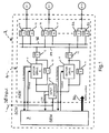
- The present invention will now be described, by way of example, with reference to the accompanying drawings, in which:
-
Fig. 1 is a block diagram of an example of the invention, being a system for distributing and controlling the use ofthree-phase electric power at a subsea hydrocarbon production well; and -
Fig. 2 is a block diagram of a sensing unit of the system. - Referring first to
Fig. 1 , three-phase (3Ø), fixed frequency AC electric power is supplied to the apparatus via asupply line 1, typically an electric umbilical cable, from a platform or vessel to a subsea control module (SCM) 2 of the apparatus, mounted on a well tree. TheSCM 2 houses a subsea electronics module (SEM) 3 and an actuator electronic module (AEM) 4. The input AC power feeds via a connector through theSCM 2 to theSEM 3, to provide basic low voltage supplies for the electronic circuitry of the apparatus, and to aninput sensing unit 5 in theAEM 4. -
Fig. 2 shows theunit 5 which containsdevices 6 to sense voltage (V) in respective ones of the three input phases anddevices 7 to sense current (I) in respective ones of the three input phases, to enable measurement of these parameters, which are required by logic circuitry installed in electronic circuitry housed in theSEM 3, outputs ofdevices SEM 3 for that purpose. Theinput sensing unit 5 has dual outputs (channels A and B) feedingmotor drive units - The
motor drive units SEM 3. The output voltage and current of each ofmotor drive units 8 and 9 (i.e. the voltage (V) applied to and the current (I) taken by the motor connected to the system at the time) are also sensed and fed back to theSEM 3 to enable measurement of these parameters for use by the logic circuitry in theSEM 3. - Further redundancy is provided in an emergency if both motor drive units were to fail, by by-passing them with high power, solid state relays (SSR's) 10 and 11.
- The output of a chosen one of motor drive unit 8 (channel A) and motor drive unit 9 (channel B) is available to drive devices on the well tree which, in the example illustrated, are three-phase electric motors M1 to M10. The channel selection is effected by the
SEM 3, which switches on via an output 36 the appropriate one of SSR 12 (for channel A) or SSR 13 (for channel B), thus providing power to a power distribution rail 34 (feeding motor selection SSR's 14,16 - - - 32) or a distribution rail 35 (feeding motor selection SSR's 15, 17 - - - 33). - The logic circuitry in
SEM 3 decides selection of the motor drive channel A or B. Initially, channel A is selected with SSR 12 switched on andSSR 13 off. The operational requirements of the well are fed to theSEM 3, such as which motor is to be operated and in which direction, the operation of the motors being multiplexed by control of the SSR's 14, 16 - - - 32 via output 36. The start-up of each motor is achieved by themotor drive unit 8 outputting a low frequency, low voltage output, initially, which increases in frequency and voltage as the motor speeds up. The characteristics of each motor start requirement are stored in a memory of theSEM 3. During the operation of each motor, the logic circuitry in theSEM 3 uses the monitored motor drive unit output current and voltage information (i.e. the motor demand) frommotor drive unit 8 with the input current and voltage information monitored by theinput sensing unit 5 and, taking into account the quiescent power requirements of the motor drive unit, assesses whether there is a fault in either the motor drive unit or the motor. Ifmotor drive unit 8 for channel A is detected to be faulty, for example when motor M1 is in operation, theSEM 3 will, via output 36, open SSR's 12 and 14, 16 - - - 32 and close SSR's 13 and 15, 17 - - - 33, thus switching to channel B. If theSEM 3 senses a fault in themotor drive unit 9 of channel B, then it will turn off the drive ofmotor drive unit 9 andclose SSR 11, reverting to emergency fixed frequency and voltage power. Likewise, a failure of supply in this situation allows SSR 10 to be closed and SSR 11 opened as an alternative emergency power path. - Thus the system is a fully automatic redundant system, which by multiplexing the output of a variable frequency, variable voltage electronic motor drive unit, reduces the overall complexity of the system. The overall effect is to achieve high reliability, making the configuration ideal for the subsea, production fluid extraction environment where replacement costs, in the event of a failure, are prohibitive, and loss of production is unacceptable.
Claims (8)
- Apparatus for use in controlling the operation of a hydrocarbon production well, comprising:supply means (1) for providing an electric power supply;a plurality of electrically operated actuating devices (M1--M10);first drive means (8) responsive to said power supply for providing a drive signal for said devices; andcontrol means (3,5,8,12,13,14 -- 32, 15 -- 33) adapted to apply said drive signal to said actuating devices in a multiplexed manner, the apparatus including second such drive means (9), and the control means being adapted to select whether to apply the drive signal of the second drive means to said actuating devices in a multiplexed manner or the drive signal from the first drive means to said actuating devices in a multiplexed manner, characterised in that:said control means is adapted to cause the drive signal of the other of the drive means instead of that of the selected drive means to be applied to said actuating devices in a multiplexed manner in the event of a fault.
- Apparatus according to claim 1, wherein said supply means (1) comprises an umbilical electric cable.
- Apparatus according to claim 1, wherein said power supply is AC.
- Apparatus according to claim 3, wherein said power supply is 3-phase AC.
- Apparatus according to claim 1, wherein said actuating devices (M1 -- M10) are electric motors.
- Apparatus according to any preceding claim, wherein said control means (3, 5, 8, 12, 13, 14 -- 32, 15 -- 33) includes means (5) for monitoring said power supply.
- Apparatus according to any preceding claim, wherein said control means (3, 5, 8, 12, 13, 14 -- 32, 15 -- 33) is adapted to monitor each of the drive means (8, 9).
- Apparatus according to any preceding claim which is located at a well tree of a hydrocarbon production well.
Applications Claiming Priority (2)
| Application Number | Priority Date | Filing Date | Title |
|---|---|---|---|
| GB0208800A GB2387977B (en) | 2002-04-17 | 2002-04-17 | Control of hydrocarbon wells |
| GB0208800 | 2002-04-17 |
Publications (3)
| Publication Number | Publication Date |
|---|---|
| EP1355037A2 EP1355037A2 (en) | 2003-10-22 |
| EP1355037A3 EP1355037A3 (en) | 2006-04-12 |
| EP1355037B1 true EP1355037B1 (en) | 2008-03-19 |
Family
ID=9935010
Family Applications (1)
| Application Number | Title | Priority Date | Filing Date |
|---|---|---|---|
| EP03252368A Expired - Lifetime EP1355037B1 (en) | 2002-04-17 | 2003-04-14 | Control of hydrocarbon wells |
Country Status (6)
| Country | Link |
|---|---|
| US (1) | US7000693B2 (en) |
| EP (1) | EP1355037B1 (en) |
| BR (1) | BR0300922B8 (en) |
| DE (1) | DE60319764T2 (en) |
| GB (1) | GB2387977B (en) |
| NO (1) | NO324863B1 (en) |
Families Citing this family (15)
| Publication number | Priority date | Publication date | Assignee | Title |
|---|---|---|---|---|
| GB0105856D0 (en) * | 2001-03-09 | 2001-04-25 | Alpha Thames Ltd | Power connection to and/or control of wellhead trees |
| GB2387977B (en) * | 2002-04-17 | 2005-04-13 | Abb Offshore Systems Ltd | Control of hydrocarbon wells |
| GB2408987B (en) * | 2003-12-09 | 2006-11-15 | Abb Offshore Systems Ltd | Controlling a fluid well |
| US20070044959A1 (en) * | 2005-09-01 | 2007-03-01 | Baker Hughes Incorporated | Apparatus and method for evaluating a formation |
| US20080203734A1 (en) * | 2007-02-22 | 2008-08-28 | Mark Francis Grimes | Wellbore rig generator engine power control |
| FR2918510B1 (en) * | 2007-07-06 | 2009-08-21 | Thales Sa | DEVICE FOR SWITCHING FROM ONE ELECTRIC SOURCE TO ANOTHER |
| US20090084558A1 (en) * | 2007-09-28 | 2009-04-02 | Robert Lewis Bloom | Electrically powered well servicing rigs |
| US8511389B2 (en) * | 2010-10-20 | 2013-08-20 | Vetco Gray Inc. | System and method for inductive signal and power transfer from ROV to in riser tools |
| US8725302B2 (en) | 2011-10-21 | 2014-05-13 | Schlumberger Technology Corporation | Control systems and methods for subsea activities |
| GB201212591D0 (en) * | 2012-07-16 | 2012-08-29 | Aker Subsea Ltd | Subsea safety system |
| US8851161B2 (en) * | 2013-01-22 | 2014-10-07 | Halliburton Energy Services, Inc. | Cross-communication between electronic circuits and electrical devices in well tools |
| BR112015010644B1 (en) * | 2013-01-22 | 2021-10-13 | Halliburton Energy Services, Inc | WELL TOOL AND METHOD FOR OPERATING A WELL TOOL IN AN UNDERGROUND WELL |
| GB2528502B (en) * | 2014-07-24 | 2018-06-13 | Ge Oil & Gas Uk Ltd | Power switching arrangement for line insulation monitoring |
| GB2536451A (en) * | 2015-03-17 | 2016-09-21 | Ge Oil & Gas Uk Ltd | Underwater hydrocarbon extraction facility |
| US10077642B2 (en) | 2015-08-19 | 2018-09-18 | Encline Artificial Lift Technologies LLC | Gas compression system for wellbore injection, and method for optimizing gas injection |
Family Cites Families (35)
| Publication number | Priority date | Publication date | Assignee | Title |
|---|---|---|---|---|
| US3219107A (en) * | 1960-09-14 | 1965-11-23 | Socony Mobil Oil Co Inc | Remote and automatic control of petroleum production |
| US3633667A (en) * | 1969-12-08 | 1972-01-11 | Deep Oil Technology Inc | Subsea wellhead system |
| US3863714A (en) * | 1973-04-17 | 1975-02-04 | Compatible Controls Systems In | Automatic gas well flow control |
| US4112687A (en) * | 1975-09-16 | 1978-09-12 | William Paul Dixon | Power source for subsea oil wells |
| US4174000A (en) * | 1977-02-26 | 1979-11-13 | Fmc Corporation | Method and apparatus for interfacing a plurality of control systems for a subsea well |
| US4102394A (en) * | 1977-06-10 | 1978-07-25 | Energy 76, Inc. | Control unit for oil wells |
| US4289996A (en) * | 1978-08-29 | 1981-09-15 | Frazer Nash Limited | Actuators |
| US4284943A (en) * | 1979-02-13 | 1981-08-18 | Electric Machinery Mfg. Company | Apparatus and method for controlling the speed of an induction motor in a closed-loop system |
| US4337829A (en) * | 1979-04-05 | 1982-07-06 | Tecnomare, S.P.A. | Control system for subsea well-heads |
| US4304989A (en) * | 1979-09-05 | 1981-12-08 | Vos H Johannes | Digital control system |
| US4526228A (en) * | 1983-01-18 | 1985-07-02 | Wynn Samuel R | Apparatus for operating a gas and oil producing well |
| USRE34111E (en) * | 1983-01-18 | 1992-10-27 | Apparatus for operating a gas and oil producing well | |
| US4687054A (en) * | 1985-03-21 | 1987-08-18 | Russell George W | Linear electric motor for downhole use |
| FR2583104B1 (en) * | 1985-06-11 | 1988-05-13 | Elf Aquitaine | COMMUNICATE SET |
| US5070904A (en) * | 1987-10-19 | 1991-12-10 | Baroid Technology, Inc. | BOP control system and methods for using same |
| SU1698876A1 (en) * | 1989-12-08 | 1991-12-15 | Специальное конструкторско-технологическое бюро с опытным производством при Белорусском государственном университете им.В.И.Ленина | Three-phase stepping motor controller |
| US5146991A (en) * | 1991-04-11 | 1992-09-15 | Delaware Capital Formation, Inc. | Method for well production |
| BR9104764A (en) * | 1991-11-01 | 1993-05-04 | Petroleo Brasileiro Sa | MULTIPLEXED ELECTROHYDRAULIC TYPE CONTROL SYSTEM USED AND A SUBMARINE PRODUCTION SYSTEM |
| DE19530721A1 (en) * | 1995-08-18 | 1997-02-20 | Kiekert Ag | Control unit e.g. for motor vehicle electric windows, anti-theft warning and locks |
| EP0852425B1 (en) * | 1995-09-08 | 2003-05-21 | Kabushiki Kaisha Yaskawa Denki | Power converter and power converting method |
| GB2328492B (en) | 1997-08-22 | 2001-08-08 | Abb Seatec Ltd | Electro-thermal actuation |
| GB2332220B (en) | 1997-12-10 | 2000-03-15 | Abb Seatec Ltd | An underwater hydrocarbon production system |
| FR2775018B1 (en) * | 1998-02-13 | 2000-03-24 | Elf Exploration Prod | METHOD OF CONDUCTING A WELL FOR PRODUCING OIL AND ACTIVE GAS BY A PUMPING SYSTEM |
| US6247536B1 (en) * | 1998-07-14 | 2001-06-19 | Camco International Inc. | Downhole multiplexer and related methods |
| DE69833091D1 (en) * | 1998-09-03 | 2006-03-30 | Cooper Cameron Corp | activation module |
| US6149683A (en) * | 1998-10-05 | 2000-11-21 | Kriton Medical, Inc. | Power system for an implantable heart pump |
| WO2000066892A1 (en) * | 1999-04-28 | 2000-11-09 | Kabushiki Kaisha Yaskawa Denki | Pump-off control for pumping jack |
| GB9913037D0 (en) | 1999-06-05 | 1999-08-04 | Abb Offshore Systems Ltd | Actuator |
| US6315523B1 (en) * | 2000-02-18 | 2001-11-13 | Djax Corporation | Electrically isolated pump-off controller |
| BR0108593A (en) * | 2000-02-22 | 2002-11-12 | Weatherford Lamb | Artificial lifting device with automated monitoring features |
| US6497281B2 (en) * | 2000-07-24 | 2002-12-24 | Roy R. Vann | Cable actuated downhole smart pump |
| US20020112860A1 (en) * | 2001-01-26 | 2002-08-22 | Baker Hughes Incorporated | Apparatus and method for electrically controlling multiple downhole devices |
| GB2382600B (en) | 2001-12-03 | 2005-05-11 | Abb Offshore Systems Ltd | Transmitting power to an underwater hydrocarbon production system |
| GB2387977B (en) * | 2002-04-17 | 2005-04-13 | Abb Offshore Systems Ltd | Control of hydrocarbon wells |
| GB2396086C (en) * | 2002-12-03 | 2007-11-02 | Vetco Gray Controls Ltd | A system for use in controlling a hydrocarbon production well |
-
2002
- 2002-04-17 GB GB0208800A patent/GB2387977B/en not_active Expired - Fee Related
-
2003
- 2003-03-31 BR BRPI0300922-0A patent/BR0300922B8/en not_active IP Right Cessation
- 2003-04-07 US US10/408,803 patent/US7000693B2/en not_active Expired - Lifetime
- 2003-04-10 NO NO20031660A patent/NO324863B1/en not_active IP Right Cessation
- 2003-04-14 DE DE60319764T patent/DE60319764T2/en not_active Expired - Lifetime
- 2003-04-14 EP EP03252368A patent/EP1355037B1/en not_active Expired - Lifetime
Also Published As
| Publication number | Publication date |
|---|---|
| EP1355037A2 (en) | 2003-10-22 |
| GB2387977A (en) | 2003-10-29 |
| GB0208800D0 (en) | 2002-05-29 |
| US20030196790A1 (en) | 2003-10-23 |
| US7000693B2 (en) | 2006-02-21 |
| DE60319764T2 (en) | 2009-04-23 |
| BR0300922B1 (en) | 2013-01-08 |
| BR0300922B8 (en) | 2013-02-19 |
| GB2387977B (en) | 2005-04-13 |
| NO324863B1 (en) | 2007-12-17 |
| BR0300922A (en) | 2004-06-08 |
| DE60319764D1 (en) | 2008-04-30 |
| NO20031660L (en) | 2003-10-20 |
| EP1355037A3 (en) | 2006-04-12 |
| NO20031660D0 (en) | 2003-04-10 |
Similar Documents
| Publication | Publication Date | Title |
|---|---|---|
| US7000693B2 (en) | Control of hydrocarbon wells | |
| US6420976B1 (en) | Underwater hydrocarbon production systems | |
| CN101326473B (en) | Method and device for redundantly powering several servomotors or drive motors by sharing a power electronics unit | |
| JP4295514B2 (en) | Control and energy supply system for seats of at least two aircraft | |
| US20050052807A1 (en) | Monitoring and control for power electronic system | |
| EP2592502B1 (en) | Safety control system | |
| WO2002072999A1 (en) | Power connection to and/or control of wellhead trees | |
| EP3282584B1 (en) | Power distribution system and method | |
| CN102900612A (en) | Control device and wind power plant | |
| KR20100091184A (en) | Electrical switchgear, particularly for connecting generators and thrusters in dynamically positioned vessels | |
| US10978975B2 (en) | Fault-tolerant electrical drive | |
| CN107810583A (en) | DC power networks | |
| AU2015366600B2 (en) | Control system and method for supply of power to active magnetic bearings in a rotating machine | |
| JP4676153B2 (en) | Power supply module mounted on a reliable board | |
| EP3134790B1 (en) | Remotely operated vehicle power management system and method of use | |
| EP1702136B1 (en) | Controlling a fluid well | |
| US6208038B1 (en) | Electrical load management method and apparatus for a vessel | |
| US7709978B2 (en) | System interface and installation with the system interface | |
| JP2007028837A (en) | Parallel power supply system for uninterruptible power supply | |
| KR20120053734A (en) | Power system stabilizer for offshore structure | |
| US20090189557A1 (en) | Method and arrangement for controlling an electric drive | |
| FI119136B (en) | Power Consumption System | |
| US20250334015A1 (en) | Subsea Christmas Tree Comprising a Control and Battery Module and Related Method | |
| CN201113546Y (en) | Vehicle mounted control electric network | |
| KR200426630Y1 (en) | Dual CPM of Digital Reduced Motherboards for Monitoring Substation Operation Status |
Legal Events
| Date | Code | Title | Description |
|---|---|---|---|
| PUAI | Public reference made under article 153(3) epc to a published international application that has entered the european phase |
Free format text: ORIGINAL CODE: 0009012 |
|
| AK | Designated contracting states |
Kind code of ref document: A2 Designated state(s): AT BE BG CH CY CZ DE DK EE ES FI FR GB GR HU IE IT LI LU MC NL PT RO SE SI SK TR |
|
| AX | Request for extension of the european patent |
Extension state: AL LT LV MK |
|
| RAP1 | Party data changed (applicant data changed or rights of an application transferred) |
Owner name: VETCO GRAY CONTROLS LIMITED |
|
| PUAL | Search report despatched |
Free format text: ORIGINAL CODE: 0009013 |
|
| AK | Designated contracting states |
Kind code of ref document: A3 Designated state(s): AT BE BG CH CY CZ DE DK EE ES FI FR GB GR HU IE IT LI LU MC NL PT RO SE SI SK TR |
|
| AX | Request for extension of the european patent |
Extension state: AL LT LV MK |
|
| 17P | Request for examination filed |
Effective date: 20061009 |
|
| AKX | Designation fees paid |
Designated state(s): DE |
|
| RBV | Designated contracting states (corrected) |
Designated state(s): DE GB |
|
| 17Q | First examination report despatched |
Effective date: 20070130 |
|
| GRAP | Despatch of communication of intention to grant a patent |
Free format text: ORIGINAL CODE: EPIDOSNIGR1 |
|
| GRAS | Grant fee paid |
Free format text: ORIGINAL CODE: EPIDOSNIGR3 |
|
| GRAA | (expected) grant |
Free format text: ORIGINAL CODE: 0009210 |
|
| AK | Designated contracting states |
Kind code of ref document: B1 Designated state(s): DE GB |
|
| REG | Reference to a national code |
Ref country code: GB Ref legal event code: FG4D |
|
| REF | Corresponds to: |
Ref document number: 60319764 Country of ref document: DE Date of ref document: 20080430 Kind code of ref document: P |
|
| PLBE | No opposition filed within time limit |
Free format text: ORIGINAL CODE: 0009261 |
|
| STAA | Information on the status of an ep patent application or granted ep patent |
Free format text: STATUS: NO OPPOSITION FILED WITHIN TIME LIMIT |
|
| 26N | No opposition filed |
Effective date: 20081222 |
|
| REG | Reference to a national code |
Ref country code: DE Ref legal event code: R082 Ref document number: 60319764 Country of ref document: DE Representative=s name: RUEGER, BARTHELT & ABEL, DE Ref country code: DE Ref legal event code: R082 Ref document number: 60319764 Country of ref document: DE Representative=s name: RUEGER, BARTHELT & ABEL PATENTANWAELTE, DE |
|
| REG | Reference to a national code |
Ref country code: DE Ref legal event code: R082 Ref document number: 60319764 Country of ref document: DE Representative=s name: RUEGER, BARTHELT & ABEL PATENTANWAELTE, DE Ref country code: DE Ref legal event code: R081 Ref document number: 60319764 Country of ref document: DE Owner name: GE OIL & GAS UK LTD., GB Free format text: FORMER OWNER: VETCO GRAY CONTROLS LTD., NAILSEA, BRISTOL, GB |
|
| REG | Reference to a national code |
Ref country code: DE Ref legal event code: R082 Ref document number: 60319764 Country of ref document: DE Representative=s name: RUEGER, BARTHELT & ABEL PATENTANWAELTE, DE Effective date: 20150422 Ref country code: DE Ref legal event code: R081 Ref document number: 60319764 Country of ref document: DE Owner name: GE OIL & GAS UK LTD., GB Free format text: FORMER OWNER: VETCO GRAY CONTROLS LTD., NAILSEA, BRISTOL, GB Effective date: 20150521 Ref country code: DE Ref legal event code: R082 Ref document number: 60319764 Country of ref document: DE Representative=s name: RUEGER, BARTHELT & ABEL PATENTANWAELTE, DE Effective date: 20150521 |
|
| PGFP | Annual fee paid to national office [announced via postgrant information from national office to epo] |
Ref country code: GB Payment date: 20220323 Year of fee payment: 20 |
|
| PGFP | Annual fee paid to national office [announced via postgrant information from national office to epo] |
Ref country code: DE Payment date: 20220322 Year of fee payment: 20 |
|
| REG | Reference to a national code |
Ref country code: DE Ref legal event code: R071 Ref document number: 60319764 Country of ref document: DE |
|
| REG | Reference to a national code |
Ref country code: GB Ref legal event code: PE20 Expiry date: 20230413 |
|
| PG25 | Lapsed in a contracting state [announced via postgrant information from national office to epo] |
Ref country code: GB Free format text: LAPSE BECAUSE OF EXPIRATION OF PROTECTION Effective date: 20230413 |