EP1355012A2 - Kit with corner connector - Google Patents
Kit with corner connector Download PDFInfo
- Publication number
- EP1355012A2 EP1355012A2 EP20030007180 EP03007180A EP1355012A2 EP 1355012 A2 EP1355012 A2 EP 1355012A2 EP 20030007180 EP20030007180 EP 20030007180 EP 03007180 A EP03007180 A EP 03007180A EP 1355012 A2 EP1355012 A2 EP 1355012A2
- Authority
- EP
- European Patent Office
- Prior art keywords
- kit
- claw
- main
- profile
- legs
- Prior art date
- Legal status (The legal status is an assumption and is not a legal conclusion. Google has not performed a legal analysis and makes no representation as to the accuracy of the status listed.)
- Withdrawn
Links
- 210000000078 claw Anatomy 0.000 claims abstract description 71
- 238000005452 bending Methods 0.000 claims description 14
- 239000002184 metal Substances 0.000 claims description 5
- 229910052751 metal Inorganic materials 0.000 claims description 5
- 238000004519 manufacturing process Methods 0.000 description 2
- 230000001066 destructive effect Effects 0.000 description 1
- 238000003780 insertion Methods 0.000 description 1
- 230000037431 insertion Effects 0.000 description 1
- 230000006641 stabilisation Effects 0.000 description 1
- 238000011105 stabilization Methods 0.000 description 1
- 238000003466 welding Methods 0.000 description 1
Images


Classifications
-
- E—FIXED CONSTRUCTIONS
- E06—DOORS, WINDOWS, SHUTTERS, OR ROLLER BLINDS IN GENERAL; LADDERS
- E06B—FIXED OR MOVABLE CLOSURES FOR OPENINGS IN BUILDINGS, VEHICLES, FENCES OR LIKE ENCLOSURES IN GENERAL, e.g. DOORS, WINDOWS, BLINDS, GATES
- E06B3/00—Window sashes, door leaves, or like elements for closing wall or like openings; Layout of fixed or moving closures, e.g. windows in wall or like openings; Features of rigidly-mounted outer frames relating to the mounting of wing frames
- E06B3/96—Corner joints or edge joints for windows, doors, or the like frames or wings
- E06B3/9624—Corner joints or edge joints for windows, doors, or the like frames or wings with means specially adapted for aligning the frontal surfaces of adjacent frame member ends
-
- E—FIXED CONSTRUCTIONS
- E04—BUILDING
- E04B—GENERAL BUILDING CONSTRUCTIONS; WALLS, e.g. PARTITIONS; ROOFS; FLOORS; CEILINGS; INSULATION OR OTHER PROTECTION OF BUILDINGS
- E04B1/00—Constructions in general; Structures which are not restricted either to walls, e.g. partitions, or floors or ceilings or roofs
- E04B1/38—Connections for building structures in general
- E04B1/58—Connections for building structures in general of bar-shaped building elements
- E04B1/5806—Connections for building structures in general of bar-shaped building elements with a cross-section having an open profile
- E04B1/5818—Connections for building structures in general of bar-shaped building elements with a cross-section having an open profile of substantially U - form
-
- E—FIXED CONSTRUCTIONS
- E06—DOORS, WINDOWS, SHUTTERS, OR ROLLER BLINDS IN GENERAL; LADDERS
- E06B—FIXED OR MOVABLE CLOSURES FOR OPENINGS IN BUILDINGS, VEHICLES, FENCES OR LIKE ENCLOSURES IN GENERAL, e.g. DOORS, WINDOWS, BLINDS, GATES
- E06B3/00—Window sashes, door leaves, or like elements for closing wall or like openings; Layout of fixed or moving closures, e.g. windows in wall or like openings; Features of rigidly-mounted outer frames relating to the mounting of wing frames
- E06B3/96—Corner joints or edge joints for windows, doors, or the like frames or wings
- E06B3/988—Corner joints or edge joints for windows, doors, or the like frames or wings specially adapted for sheet metal frame members with an open U-shaped cross-section
- E06B3/9885—Mitre joints
-
- F—MECHANICAL ENGINEERING; LIGHTING; HEATING; WEAPONS; BLASTING
- F16—ENGINEERING ELEMENTS AND UNITS; GENERAL MEASURES FOR PRODUCING AND MAINTAINING EFFECTIVE FUNCTIONING OF MACHINES OR INSTALLATIONS; THERMAL INSULATION IN GENERAL
- F16B—DEVICES FOR FASTENING OR SECURING CONSTRUCTIONAL ELEMENTS OR MACHINE PARTS TOGETHER, e.g. NAILS, BOLTS, CIRCLIPS, CLAMPS, CLIPS OR WEDGES; JOINTS OR JOINTING
- F16B7/00—Connections of rods or tubes, e.g. of non-circular section, mutually, including resilient connections
- F16B7/04—Clamping or clipping connections
- F16B7/044—Clamping or clipping connections for rods or tubes being in angled relationship
- F16B7/0446—Clamping or clipping connections for rods or tubes being in angled relationship for tubes using the innerside thereof
- F16B7/0473—Clamping or clipping connections for rods or tubes being in angled relationship for tubes using the innerside thereof with hook-like parts gripping, e.g. by expanding, behind the flanges of a profile
Definitions
- the present invention relates to a kit for connecting a corner a mitred C or U profile made of at least one corner connector and a profile corner made from at least one C or U profile, wherein the C or U profile is a main page with an adjoining connecting page to a secondary side, the profile corner through two legs of the C or U profile is formed, the secondary sides and connecting sides of the legs of the C or U-profiles are mitered to each other and the main sides of the legs of the C or U profile are connected to one another along a connecting line.
- C or U profiles are known from the prior art, which are mitered to one another are cut. These C or U profiles that collide on the cut surfaces are welded e.g. Spot welding on the cut surfaces connected with each other. However, such welds are timely and expensive.
- a corner connector as one inside the C or U profile, in both legs on both sides the connecting line bracing claw is designed to lock the Ensure profile corner.
- the claw is essentially in a further variant is designed plane-parallel to a connection side, which provides enough space is available inside the C or U profile to accommodate other components. For example, Simply lay the cable in the kit.
- the claw is a stamped and bent part made of sheet metal, since the Manufacturing such mass products is extremely inexpensive to accomplish.
- This variant shows if two claws can be used in one channel additional advantages. This further limits the channel's twistability and a higher load capacity of the channel can be guaranteed.
- a claw is a main surface
- two main legs and adjoining this has two side legs connected to the main surface on bending lines another advantage.
- a particularly durable connection results when the lower legs are along two bending lines are angled by a maximum of 90 ° from the main surface.
- the kit 1 consisting of two legs 2 and 3, is constructed from C-profiles 4, 5, 6 and 7, and two claws 8 and 9 are shown.
- the C profiles are 4 and 5, seamlessly connected to each other on the main pages 10 and 11.
- the connection side 12, of the C-profile 4 runs parallel to the connection side 13 of the C-profile 5.
- the connection side 12 forms a right side with the main side 10 of the C-profile 4 Angle.
- the connection side 13 forms one with the main side 11 of the C-profile 5 right angle.
- the main pages 10 and 11 of the C-profiles 4 and 5 form a 180 ° angle.
- the secondary side 14 connects seamlessly to the connecting side 12 of the C-profile 4 at a right angle, parallel to the main side 10, on the connecting side 13 addressed to.
- the secondary side 15 connects to the connecting side 13 of the C profile 5 seamlessly at a right angle.
- the side 15 runs parallel to Main page 11 and points to the connection side 12.
- the secondary pages are 14 and 15 parallel to each other and converge.
- the leg 3 consists of two C-profiles 6 and 7.
- the C-profile 6 has a main side 16, a connecting side 18 adjoining this and an adjoining one Connection side 20 on.
- the main page 16 forms with the connection side 18 a 90 ° angle.
- the connecting side 18 forms one with the secondary side 20 90 ° angle.
- the C-profile 7 has a main side 17, a connecting side 19 and a secondary side 21 on.
- the main side 17 and the connecting side 19 form a 90 ° angle.
- the connecting side 19 and the secondary side 21 also form a 90 ° angle.
- the connecting sides 18 and 19 run parallel to one another.
- the side pages 21 and 20 also run parallel to one another.
- the secondary pages 20 and 21 run parallel to the main pages 16 and 17.
- the main pages 16 and 17 are together seamlessly connected and form a 180 ° angle.
- Pages 16 to 21 of the leg 3, the C-profiles 6 and 7, are made from a stamped and bent part made of sheet metal.
- the secondary pages 14, 15, 20 and 21 have further folds.
- the legs 2 and 3 of the kit 1 are made from a stamped and bent part. there are the legs 2 and 3 via the main pages 10 and 11 with the main pages 16 and 17 connected.
- the main pages 10 and 11 form with the main pages 16 and 17 a connecting line 22.
- the main pages 10 and 11 form on the connecting line 22 with the main sides 16 and 17 at a 90 ° angle in this embodiment.
- Either the connecting sides 12 and 13 as well as the secondary sides 14 and 15 are closed the connecting sides 18 and 19 and to the secondary sides 20 and 21 mitred cut to each other.
- the claw 8 and the claw 9 clamp the two legs 2 and 3 of the kit 1.
- the claw 8 lies on the connection side 13 of the C-profile 5 and on the connection side 19 of the C-profile 7 flat.
- the claw 8 has a main leg 23 and a main leg 24.
- the two Main legs 23 and 24 are jagged.
- the main leg 23 of the Claw 8 braces in the main side 11 of the C-profile 5 in the leg 2.
- the claw 9 is designed like the claw 8.
- the claw 9 has two main legs 25 and 26 on.
- the main leg 25 and the main leg 26 are designed jagged.
- the main leg 25 braces in the main side 10 of the profile 4 in Leg 2.
- the main leg 26 is braced in the main side 16 of the C-profile 6 of the leg 3.
- the claw lies flat on the connecting sides 12 and 18.
- the claws 8 and 9 are located inside that formed by the C-profiles 4, 5, 6 and 7 Space.
- the claw 8 has the side legs 27 and 28.
- the claw 9 has the Lower leg 29 and 30 on.
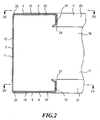
- FIG. 2 shows a section through the leg 2 along the line II from FIG. 1.
- the C-profiles 4 and 5 are cut. It is the main pages 10 and 11, the connecting sides 12 and 13 and the secondary sides 14 and 15 of the two C-profiles 4 and 5 can be seen.
- the claws 8 and 9 are each on the connecting surface 13 or 12 flat.
- the main surface 31 of the claw 8 lies on the connection side 13 on.
- the main surface 32 of the claw 9 lies on the connection side 12 on.
- a secondary leg 27 of the claw 8 forms a 90 ° angle with the main surface 31.
- the lower leg lies against the secondary side 15.
- the lower leg 27 is jagged at the end.
- the end 15 has a bend at the end on which the jagged side leg 27 braces and claws.
- the side 14 of the C-profile 4 has an inward direction Main page 10 directional bend. This bend tightens jagged side leg 29.
- the side leg 29 of the claw 9 has a 90 ° angle to the main surface 32 of the claw 9.
- the side leg 29 runs parallel to the main page 10.
- the main leg 23 is braced in the main page 11.
- the main leg 25 tensions in the main side 10.
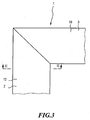
- FIG. 3 shows the legs 2 and 3 in a plan view along the line III from FIG. 2 the kit 1 with their connecting sides 12 and 18 can be seen.
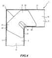
- FIG. 4 shows a longitudinal section through the kit 1 from FIG. 2.
- the claw 8 has the main legs 23 and 24.
- This Main legs 23 and 24 are jagged.
- the main leg 23 braced in the main page 11.
- a main leg 24 of the claw 8 is clamped in the Main side 17.
- a main surface 31 of the claw 8 has a recess 33. This Recess 33 enables simple insertion into legs 2 and 3.
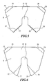
- Fig. 5 shows a claw 8, which is identical to a claw 9. Just the position Type of use and / or location in the kit is different.
- the claw 8 has a metal one Body on.
- the claw 8 contains a main surface 31, a recess 33 and the main legs 23 and 24.
- the main legs 23 and 24 are designed jagged.
- the main legs 23 and 24 have bending lines 35 and 36.
- the main legs 23 and 24 are along the bend lines 35 and 36 at a 5 ° angle to the main surface 31 bent upwards.
- the lower legs 27 and 28, which are jagged, are in this embodiment along the bending lines 37 and 38 at a 90 ° angle bent up to the main surface 31.
- FIG. 6 shows the claw 8. It has the main legs 23 and 24 running along it of the bending lines 35 and 36 of the main surface 31 are designed to be bendable.
- the side legs 27 and 28 are designed to be bendable along the bending lines 37 and 38.
- a recess 33 is kept free from the main surface 31.
- FIG. 7 shows the angle ⁇ , which, as described in FIG. 5, comprises 5 °.
- the Claw 8 has the lower leg 27.
- the bending line 37 is between the lower leg 27 and the main surface 31 can be seen.
- the bending line 35, between the The main leg 23 and the main surface 31 of the claw 8 can also be seen.
- Fig. 8 the claw 8 is shown in a rear view from which the angle ⁇ is measured between a plane through the major surface 31 and a plane through either the main leg 23 or through the main leg 24 can be seen.
- the bending lines 35 and 36 are between the main surface 31 and the main leg 23 on the one hand and the main surface 31 and the main leg 24 on the other hand.
- the lower legs 27 and 28 can also be seen.
- FIG. 9 is a rear perspective view of the kit.
- the main pages 16 and 17 of the leg 3 are along the bending line 22 with the main sides 10 and 11 of the leg 2 connected.
Landscapes
- Engineering & Computer Science (AREA)
- Civil Engineering (AREA)
- Structural Engineering (AREA)
- Architecture (AREA)
- Physics & Mathematics (AREA)
- Electromagnetism (AREA)
- Toys (AREA)
- Tents Or Canopies (AREA)
Abstract
Description
Die vorliegende Erfindung bezieht sich auf einen Bausatz zum Verbinden einer Ecke eines auf Gehrung geschnittenen C- oder U-Profils aus mindestens einem Eckverbinder und einer aus mindestens einem C- oder U-Profil gefertigten Profilecke, wobei das C- oder U-Profil eine Hauptseite mit einer daran anschließenden Verbindungsseite zu einer Nebenseite aufweist, die Profilecke durch zwei Schenkel des C- oder U-Profils gebildet ist, die Nebenseiten und Verbindungsseiten der Schenkel des C- oder U-Profils auf Gehrung zueinander geschnitten sind und die Hauptseiten der Schenkel des C- oder U-Profils entlang einer Verbindungslinie miteinander verbunden sind.The present invention relates to a kit for connecting a corner a mitred C or U profile made of at least one corner connector and a profile corner made from at least one C or U profile, wherein the C or U profile is a main page with an adjoining connecting page to a secondary side, the profile corner through two legs of the C or U profile is formed, the secondary sides and connecting sides of the legs of the C or U-profiles are mitered to each other and the main sides of the legs of the C or U profile are connected to one another along a connecting line.
Aus dem Stand der Technik sind C- oder U-Profile bekannt, die zueinander auf Gehrung geschnitten sind. Diese C- oder U-Profile, welche an den Schnittflächen zusammenstoßen, werden durch Schweißen z.B. Punktschweißen an den Schnittflächen miteinander verbunden. Derartige Schweißverbindungen sind jedoch zeit- und kostenintensiv.C or U profiles are known from the prior art, which are mitered to one another are cut. These C or U profiles that collide on the cut surfaces are welded e.g. Spot welding on the cut surfaces connected with each other. However, such welds are timely and expensive.
Es ist somit Aufgabe der vorliegenden Erfindung, einen einfach zu konstruierenden, einfach herzustellenden und vor allen Dingen kostengünstigen Bausatz aus einem C-oder U-Profil darzustellen.It is therefore an object of the present invention to provide an easy to construct easy to manufacture and above all inexpensive kit from a C or Represent U-profile.
Diese Aufgabe wird erfindungsgemäß durch einen Bausatz gelöst, bei dem ein Eckverbinder als eine sich im Inneren des C- oder U-Profils, in beiden Schenkeln beiderseits der Verbindungslinie verspannende Kralle ausgebildet ist, um ein Arretieren der Profilecke zu gewährleisten.This object is achieved by a kit in which a corner connector as one inside the C or U profile, in both legs on both sides the connecting line bracing claw is designed to lock the Ensure profile corner.
Dadurch, dass die Kralle in den Schenkeln des Profils eine Spannung aufbaut, die Schenkel des Profils, die an der Verbindungslinie zusammenhängend ausgestaltet sind, sich jedoch nicht voneinander trennen, wird die Profilecke arretiert, wodurch eine Verformung verhindert wird. Die Montage einer erfindungsgemäßen Kralle in ein erfindungsgemäßes C- oder U-Profil zum Erreichen des Bausatzes ist schnell und einfach zu bewerkstelligen. Es bedarf keines besonders geschulten Personals, um die stabile Ausgestaltung der Profilecke zu gewährleisten, wodurch erhöhte Lohnkosten vermieden werden und eine kostengünstige Alternative zu bestehenden Bausätzen gestellt wird. The fact that the claw builds up a tension in the legs of the profile Leg of the profile, which is contiguous at the connecting line are, but do not separate from each other, the profile corner is locked, whereby deformation is prevented. The assembly of a claw according to the invention in one C or U profile according to the invention for reaching the kit is fast and easy to do. No specially trained personnel are required to to ensure the stable design of the profile corner, thereby increasing labor costs avoided and an inexpensive alternative to existing kits is provided.
Vorteilhafte Ausgestaltungen sind in den Unteransprüchen wiedergegeben.Advantageous configurations are given in the subclaims.
Besonders vorteilhaft ist es, wenn die Kralle sowohl zwischen der Innenseite der Hauptseite und der Innenseite der Nebenseite des einen Schenkels der Profilseite, als auch zwischen der Innenseite der Hauptseite und der Innenseite der Nebenseite des anderen Schenkels verspannend ausgestaltet ist. Hierdurch kann die Spannung, die für die Stabilisierung der Profilecke benötigt wird, erreicht werden. Dadurch können Kräfte aufgefangen und kompensiert werden, welche zum Verformen der Schenkel des Profils geeignet wären. Dadurch ist eine zerstörungsresistente Ausgestaltungsform des Bausatzes gewährleistet.It when the claw between both the inside of the Main side and the inside of the side of one leg of the profile side, as well as between the inside of the main page and the inside of the side of the other leg is designed to tension. This allows the tension, required for the stabilization of the profile corner can be achieved. This allows Forces are absorbed and compensated for, which deform the legs of the profile would be suitable. This is a non-destructive design guaranteed of the kit.
Dadurch, dass die Kralle an den, den Nebenseiten zugewandten Abschnitten eine Umbiegung aufweist, die der Nebenseite zumindest teilweise anliegt, kann eine besonders vorteilhafte Ausprägung erreicht werden. Durch diese Ausprägung kann ein Abstützten der Kralle an dem C- oder U-Profil und somit ein Verspannen der Kralle innerhalb des C- oder U-Profils erreicht werden. Zusätzlich dazu kann eine Selbstausrichtung der Kralle innerhalb des C- oder U-Profils stattfinden, was zu einer einfachen Montage und damit geringeren Lohnkosten führt.The fact that the claw on the, the sides facing sections a Bending, which at least partially abuts the secondary side, can be a special advantageous expression can be achieved. With this expression, a Supporting the claw on the C or U profile and thus tightening the claw can be achieved within the C or U profile. In addition to this, self-alignment the claw take place within the C or U profile, resulting in a simple one Assembly and thus lower labor costs.
Besonders vorteilhaft ist es, wenn gemäß einer Variante die an den Haupt- und Nebenseiten anliegenden Enden der Kralle zackig ausgestaltet sind. Dadurch wird die Haftreibung erhöht und ein Herausfallen der Kralle verhindert. Eine längere Lebensdauer, selbst unter extremen Einsätzen, ist die Folge.It is particularly advantageous if, according to one variant, that on the main and secondary sides adjacent ends of the claw are jagged. This will make the Stiction increases and the claw does not fall out. A longer lifespan, the result, even under extreme conditions.
Besonders vorteilhaft ist es, wenn die Kralle in einer weiteren Variante im Wesentlichen planparallel zu einer Verbindungsseite ausgestaltet ist, wodurch genügend Bauraum im Inneren des C- oder U-Profils zur Verfügung steht, um weitere Bauteile unterzubringen. So lassen sich z.B. Kabel äußerst einfach in dem Bausatz verlegen.It is particularly advantageous if the claw is essentially in a further variant is designed plane-parallel to a connection side, which provides enough space is available inside the C or U profile to accommodate other components. For example, Simply lay the cable in the kit.
Besonders vorteilhaft ist es, wenn die Kralle ein Stanz-Biegeteil aus Blech ist, da die Herstellung solcher Massenprodukte äußerst kostengünstig zu bewerkstelligen ist.It is particularly advantageous if the claw is a stamped and bent part made of sheet metal, since the Manufacturing such mass products is extremely inexpensive to accomplish.
Wenn an die Nebenseite des C- oder U-Profils eine Zusatzseite in einer besonderen Ausführungsform anschließt, an die sich ein Nebenschenkel der Kralle abstützt, stellt sich der Vorteil einer zusätzlichen Sicherung gegen Verwinden des C- oder U-Profils ein. If there is an additional side in a special on the side of the C or U profile Embodiment follows, on which a side leg of the claw is supported the advantage of an additional safeguard against twisting of the C or U profile on.
Wenn zwei Krallen in einem Kanal einsetzbar sind, zeigen sich bei dieser Variante weitere Vorteile. So kann die Verwindbarkeit des Kanals weiter eingeschränkt werden und eine höhere Belastbarkeit des Kanals gewährleistet werden.This variant shows if two claws can be used in one channel additional advantages. This further limits the channel's twistability and a higher load capacity of the channel can be guaranteed.
Besonders vorteilhaft ist es, wenn in einer Variante der Erfindung vier C- oder U-Profile und zwei Krallen zu einem Bausatz kombinierbar sind, da dann eine besonders stabile und vielseitige Einsatzform gewährleistbar ist.It is particularly advantageous if, in a variant of the invention, four C or U profiles and two claws can be combined to form a kit, because then one is special stable and versatile form of use can be guaranteed.
Wenn eine Kralle eine Hauptfläche, zwei an diese anschließende Hauptschenkel und zwei mit der Hauptfläche an Biegelinien verbundene Nebenschenkel aufweist, stellt sich ein weiterer Vorteil ein. In einer solchen Ausgestaltungsvariante lässt sich ein Zusammenbau des Bausatzes schneller bewerkstelligen.If a claw is a main surface, two main legs and adjoining this has two side legs connected to the main surface on bending lines another advantage. In such an embodiment variant, one can Assemble the kit faster.
Eine besonders haltbare Verbindung ergibt sich, wenn die Nebenschenkel entlang zweier Biegelinien um maximal 90° von der Hauptfläche abgewinkelt sind.A particularly durable connection results when the lower legs are along two bending lines are angled by a maximum of 90 ° from the main surface.
Leichte Montierbarkeit und schneller Zusammenbau lässt sich erreichen, wenn in der Hauptfläche eine Aussparung vorgesehen ist.Easy assembly and quick assembly can be achieved if in the Main surface a recess is provided.
Besonders vorteilhaft ist es, wenn zumindest bei einer Kralle zwischen einer Ebene durch die Hauptfläche und jeweils einer Ebene durch die Hauptschenkel ein Winkel von mindestens 2° vorliegt. Dann lässt sich eine leichte und schnell herzustellende Bausatzvariante produzieren, durch die kurze Lieferzeiten ermöglicht werden.It is particularly advantageous if there is at least one claw between one plane through the main surface and one level through the main legs an angle of at least 2 °. Then you can create a light and quick one Produce a kit variant that enables short delivery times.
Wenn zwei C- oder U-Profile mit mindestens einer Kralle zu einem Kanal kombiniert werden, kann sich dies in dieser Ausgestaltungsform der Erfindung als besonders vorteilhaft erweisen, da sich dann eine höhere Anzahl an Verwendungsmöglichkeiten für den Bausatz ergeben.When two C or U profiles combined with at least one claw to form a channel this can prove to be special in this embodiment of the invention prove to be advantageous because there is a greater number of possible uses result for the kit.
Im Folgenden werden Ausführungsbeispiele der vorliegenden Erfindung anhand einer Zeichnung näher erläutert. Es zeigen:
- Fig. 1
- eine perspektivische Ansicht des Bausatzes, bestehend aus sowohl zwei C-förmigen Profilen, die miteinander nahtlos verbunden sind und insgesamt zwei Schenkel aufweisen, die über eine Verbindungslinie miteinander verbunden sind, und zwei Krallen des Bausatzes,
- Fig. 2
- einen Querschnitt durch einen Schenkel der zwei C-Profile und zwei Krallen entlang der Linie II aus Fig. 1,
- Fig. 3
- eine Draufsicht auf den Bausatz entlang der Linie III aus Fig. 2,
- Fig. 4
- einen Längsschnitt durch den Bausatz in Höhe der Linie IV aus Fig. 2,
- Fig. 5
- eine Detaildraufsicht der Kralle des Bausatzes aus den Fig. 1 bis 4,
- Fig. 6
- ein Abwickelbild in Draufsicht der Kralle aus Fig. 5,
- Fig. 7
- eines Seitenansicht der Kralle aus Fig. 5,
- Fig. 8
- eine Rückansicht der Kralle aus Fig. 5 und
- Fig. 9
- eine perspektivische Rückansicht des Bausatzes aus Fig. 1.
- Fig. 1
- 2 shows a perspective view of the kit, consisting of both two C-shaped profiles which are seamlessly connected to one another and have a total of two legs which are connected to one another via a connecting line, and two claws of the kit,
- Fig. 2
- 3 shows a cross section through one leg of the two C-profiles and two claws along the line II from FIG. 1,
- Fig. 3
- 3 shows a plan view of the kit along the line III from FIG. 2,
- Fig. 4
- 2 shows a longitudinal section through the kit at the level of line IV from FIG. 2,
- Fig. 5
- 2 shows a detailed top view of the claw of the kit from FIGS. 1 to 4,
- Fig. 6
- 4 shows a development view in top view of the claw from FIG. 5,
- Fig. 7
- 5 shows a side view of the claw from FIG. 5,
- Fig. 8
- a rear view of the claw of Fig. 5 and
- Fig. 9
- 2 shows a perspective rear view of the kit from FIG. 1.
In Fig. 1 ist der Bausatz 1, bestehend aus zwei Schenkeln 2 und 3, aufgebaut aus C-Profilen
4, 5, 6 und 7, und zwei Krallen 8 und 9 dargestellt. Dabei sind die C-Profile 4
und 5, an den Hauptseiten 10 und 11 miteinander nahtlos verbunden. Die Verbindungsseite
12, des C-Profils 4 verläuft parallel zur Verbindungsseite 13 des C-Profils
5. Die Verbindungsseite 12 bildet mit der Hauptseite 10 des C-Profils 4 einen rechten
Winkel. Die Verbindungsseite 13 bildet mit der Hauptseite 11 des C-Profils 5 einen
rechten Winkel. Die Hauptseiten 10 und 11 der C-Profile 4 und 5 bilden einen 180°-Winkel.
Die Nebenseite 14 schließt an die Verbindungsseite 12 des C-Profils 4 nahtlos
in einem rechten Winkel, parallel zur Hauptseite 10, auf die Verbindungsseite 13
gerichtet an. Die Nebenseite 15 schließt an die Verbindungsseite 13 des C-Profils 5
nahtlos in einem rechten Winkel an. Dabei verläuft die Nebenseite 15 parallel zur
Hauptseite 11 und zeigt auf die Verbindungsseite 12. Somit sind die Nebenseiten 14
und 15 zueinander parallel und laufen aufeinander zu. In diesem Ausführungsbeispiel
sind die einzelnen Seiten 10 bis 15 des einen Schenkels 2 des Bausatzes aus einem
Stanz-Biegeteil aus Blech gefertigt. In Fig. 1, the
Der Schenkel 3 besteht aus zwei C-Profilen 6 und 7. Das C-Profil 6 weist eine Hauptseite
16, eine an diese anschließende Verbindungsseite 18 und eine an diese anschließende
Verbindungsseite 20 auf. Die Hauptseite 16 bildet mit der Verbindungsseite
18 einen 90°-Winkel. Die Verbindungsseite 18 bildet mit der Nebenseite 20 einen
90°-Winkel.The
Das C-Profil 7 weist eine Hauptseite 17, eine Verbindungsseite 19 und eine Nebenseite
21 auf. Dabei bilden die Hauptseite 17 und die Verbindungsseite 19 einen 90°-Winkel.
Auch bilden die Verbindungsseite 19 und die Nebenseite 21 einen 90°-Winkel.
Die Verbindungsseiten 18 und 19 verlaufen zueinander parallel. Die Nebenseiten
21 und 20 verlaufen ebenso zueinander parallel. Die Nebenseiten 20 und 21
verlaufen zu den Hauptseiten 16 und 17 parallel. Die Hauptseiten 16 und 17 sind miteinander
nahtlos verbunden und bilden einen 180°-Winkel.The C-
Die Nebenseiten 20 und 21 laufen aufeinander zu. Die Seiten 16 bis 21 des Schenkels
3, der C-Profile 6 und 7, sind aus einem Stanz-Biegeteil aus Blech gefertigt.The
Die Nebenseiten 14, 15, 20 und 21 weisen weitere Umfalzungen auf.The
Die Schenkel 2 und 3 des Bausatzes 1 sind aus einem Stanz-Biegeteil gefertigt. Dabei
sind die Schenkel 2 und 3 über die Hauptseiten 10 und 11 mit den Hauptseiten 16
und 17 verbunden. Die Hauptseiten 10 und 11 bilden mit den Hauptseiten 16 und 17
eine Verbindungslinie 22. Die Hauptseiten 10 und 11 bilden an der Verbindungslinie
22 mit den Hauptseiten 16 und 17 einen 90°-Winkel in dieser Ausführungsform. Sowohl
die Verbindungsseiten 12 und 13 als auch die Nebenseiten 14 und 15 sind zu
den Verbindungsseiten 18 und 19 und zu den Nebenseiten 20 und 21 auf Gehrung
zueinander geschnitten.The
Die Kralle 8 und die Kralle 9 verspannen die zwei Schenkel 2 und 3 des Bausatzes 1.
Die Kralle 8 liegt dabei auf der Verbindungsseite 13 des C-Profils 5 und auf der Verbindungsseite
19 des C-Profils 7 flächig an.The
Die Kralle 8 weist einen Hauptschenkel 23 und einen Hauptschenkel 24 auf. Die beiden
Hauptschenkel 23 und 24 sind zackig ausgebildet. Der Hauptschenkel 23 der
Kralle 8 verspannt sich in der Hauptseite 11 des C-Profils 5 im Schenkel 2. Der
Hauptschenkel 24, der ebenso zackig ausgestaltet ist, verspannt sich in der Hauptseite
17 des C-Profils 7 im Schenkel 3.The
Die Kralle 9 ist wie die Kralle 8 ausgestaltet. Die Kralle 9 weist zwei Hauptschenkel
25 und 26 auf. Der Hauptschenkel 25 und der Hauptschenkel 26 sind zackig ausgestaltet.
Der Hauptschenkel 25 verspannt sich in der Hauptseite 10 des Profils 4 im
Schenkel 2. Der Hauptschenkel 26 verspannt sich in der Hauptseite 16 des C-Profils
6 des Schenkels 3. Die Kralle liegt flächig auf den Verbindungsseiten 12 und 18 an.
Die Krallen 8 und 9 liegen im Inneren des von den C-Profilen 4, 5, 6 und 7 gebildeten
Raums. Die Kralle 8 weist die Nebenschenkel 27 und 28 auf. Die Kralle 9 weist die
Nebenschenkel 29 und 30 auf.The
In Fig. 2 ist ein Schnitt durch den Schenkel 2 entlang der Linie II aus Fig. 1 hergestellt.
Dabei sind die C-Profile 4 und 5 geschnitten. Es sind die Hauptseiten 10 und
11, die Verbindungsseiten 12 und 13 und die Nebenseiten 14 und 15 der beiden C-Profile
4 und 5 zu erkennen. Die Krallen 8 und 9 liegen jeweils an der Verbindungsfläche
13 bzw. 12 flächig an. Die Hauptfläche 31 der Kralle 8 liegt an der Verbindungsseite
13 an. Die Hauptfläche 32 der Kralle 9 liegt an der Verbindungsseite 12
an. Ein Nebenschenkel 27 der Kralle 8 bildet mit der Hauptfläche 31 einen 90°-Winkel.
Dabei liegt der Nebenschenkel an der Nebenseite 15 an. Der Nebenschenkel
27 ist am Ende zackig ausgestaltet. Die Nebenseite 15 weist am Ende eine Umbiegung
auf, an der sich der zackig ausgestaltete Nebenschenkel 27 verspannt und verkrallt.
Die Nebenseite 14 des C-Profils 4 weist eine nach innen in Richtung der
Hauptseite 10 gerichtete Umbiegung auf. An dieser Umbiegung verspannt sich ein
zackig ausgestalteter Nebenschenkel 29. Der Nebenschenkel 29 der Kralle 9 weist
einen 90°-Winkel zur Hauptfläche 32 der Kralle 9 auf. Der Nebenschenkel 29 verläuft
parallel zur Hauptseite 10. Die Hauptschenkel 23 verspannt sich in der Hauptseite 11.
Der Hauptschenkel 25 verspannt sich in der Hauptseite 10.FIG. 2 shows a section through the
Von dem Schenkel 3 sind die Hauptseiten 16 und 17 sowie die Nebenseiten 20 und
21 zu erkennen.From the
In Fig. 3 sind in einer Draufsicht entlang der Linie III aus Fig. 2 die Schenkel 2 und 3
des Bausatzes 1 mit deren Verbindungsseiten 12 und 18 zu erkennen. 3 shows the
In Fig. 4 ist ein Längsschnitt durch den Bausatz 1 aus Fig. 2 zu erkennen. Hier sind
die Schenkel 2 und 3 des Bausatzes 1 zu erkennen. Sie sind an der Verbindungslinie
22 miteinander verbunden. Die Kralle 8 weist die Hauptschenkel 23 und 24 auf. Diese
Hauptschenkel 23 und 24 sind zackig ausgestaltet. Der Hauptschenkel 23 verspannt
sich in der Hauptseite 11. Ein Hauptschenkel 24 der Kralle 8 verspannt sich in der
Hauptseite 17. Eine Hauptfläche 31 der Kralle 8 weist eine Aussparung 33 auf. Diese
Aussparung 33 ermöglicht ein einfaches Einsetzen in die Schenkel 2 und 3.FIG. 4 shows a longitudinal section through the
Fig. 5 zeigt eine Kralle 8, die baugleich zu einer Kralle 9 ist. Lediglich die Position,
Einsetzart und/oder Lage im Bausatz ist unterschiedlich. Die Kralle 8 weist einen metallenen
Körper auf. Die Kralle 8 enthält eine Hauptfläche 31, eine Aussparung 33 und
die Hauptschenkel 23 und 24. Die Hauptschenkel 23 und 24 sind zackig ausgestaltet.
Die Hauptschenkel 23 und 24 weisen Biegelinien 35 und 36 auf. Die Hauptschenkel
23 und 24 sind entlang der Biegelinien 35 und 36 in einem 5°-Winkel zur Hauptfläche
31 nach oben gebogen. Die Nebenschenkel 27 und 28, die zackig ausgestaltet sind,
sind in diesem Ausführungsbeispiel entlang der Biegelinien 37 und 38 in einem 90°-Winkel
zur Hauptfläche 31 nach oben gebogen.Fig. 5 shows a
In Fig. 6 ist die Kralle 8 dargestellt. Sie weist die Hauptschenkel 23 und 24, die entlang
der Biegelinien 35 und 36 der Hauptfläche 31 biegbar ausgestaltet sind, auf. Die
Nebenschenkel 27 und 28 sind entlang der Biegelinien 37 und 38 biegbar ausgestaltet.
Aus der Hauptfläche 31 ist eine Aussparung 33 freigehalten.6 shows the
In Fig. 7 ist der Winkel α, der wie in Fig. 5 beschrieben, 5° umfasst, dargestellt. Die
Kralle 8 weist den Nebenschenkel 27 auf. Die Biegelinie 37 ist zwischen dem Nebenschenkel
27 und der Hauptfläche 31 ersichtlich. Die Biegelinie 35, zwischen dem
Hauptschenkel 23 und der Hauptfläche 31 der Kralle 8, ist ebenso ersichtlich.FIG. 7 shows the angle α, which, as described in FIG. 5, comprises 5 °. The
In Fig. 8 ist die Kralle 8 in einer Rückansicht dargestellt, aus der die Winkel α gemessen
zwischen einer Ebene durch die Hauptfläche 31 und einer Ebene entweder durch
den Hauptschenkel 23 oder durch den Hauptschenkel 24 ersichtlich werden. Die Biegelinien
35 und 36 sind zwischen der Hauptfläche 31 und dem Hauptschenkel 23 einerseits
und der Hauptfläche 31 und dem Hauptschenkel 24 andererseits dargestellt.
Die Nebenschenkel 27 und 28 sind ebenso zu erkennen. In Fig. 8 the
Fig. 9 ist eine perspektivische Rückansicht des Bausatzes darstellt. Die Hauptseiten
16 und 17 des Schenkels 3 sind entlang der Biegelinie 22 mit den Hauptseiten 10 und
11 des Schenkels 2 verbunden.9 is a rear perspective view of the kit. The
Claims (14)
Applications Claiming Priority (2)
| Application Number | Priority Date | Filing Date | Title |
|---|---|---|---|
| DE10217574 | 2002-04-19 | ||
| DE2002117574 DE10217574B3 (en) | 2002-04-19 | 2002-04-19 | Kit with corner connector |
Publications (1)
| Publication Number | Publication Date |
|---|---|
| EP1355012A2 true EP1355012A2 (en) | 2003-10-22 |
Family
ID=28458934
Family Applications (1)
| Application Number | Title | Priority Date | Filing Date |
|---|---|---|---|
| EP20030007180 Withdrawn EP1355012A2 (en) | 2002-04-19 | 2003-03-28 | Kit with corner connector |
Country Status (2)
| Country | Link |
|---|---|
| EP (1) | EP1355012A2 (en) |
| DE (1) | DE10217574B3 (en) |
Cited By (1)
| Publication number | Priority date | Publication date | Assignee | Title |
|---|---|---|---|---|
| WO2023186238A1 (en) * | 2022-03-31 | 2023-10-05 | Vkr Holding A/S | A roof window comprising a sash with profile elements and method of manufacturing a roof window |
Family Cites Families (10)
| Publication number | Priority date | Publication date | Assignee | Title |
|---|---|---|---|---|
| DE7418811U (en) * | 1974-11-07 | Kemhadjian P | Picture frames formed essentially from L-shaped profiled profile strip sections | |
| US2717667A (en) * | 1953-10-01 | 1955-09-13 | Joseph C Bancroft | Window frame construction |
| GB1084298A (en) * | 1965-06-14 | 1967-09-20 | The Schlegel Manufacturing Company | Garnishing bead miter joint and method of making same |
| DE1982150U (en) * | 1967-11-28 | 1968-03-28 | Loeffler & Ross K G Metallbau | CORNER CONNECTION FOR LIGHT METAL PROFILES. |
| US4240765A (en) * | 1979-04-27 | 1980-12-23 | Offterdinger Hermann F | Corner construction |
| WO1984002559A1 (en) * | 1982-12-29 | 1984-07-05 | Japan Art Kikaku Co Ltd | Coupling device for formed frame |
| DE4112181A1 (en) * | 1991-04-13 | 1992-10-15 | Elram Wintergartentechnik Gmbh | Angular butt joint between channel sections - has tie bolts engaging with protruding stiffening members in undercut grooves |
| US5201787A (en) * | 1991-05-31 | 1993-04-13 | Usg Interiors, Inc. | Trim system for suspension ceilings |
| FR2701510B1 (en) * | 1993-02-15 | 1995-04-21 | Alcan France | Surface bracket for window frames or the like in metal profiles. |
| DE10126278C2 (en) * | 2001-05-29 | 2003-06-12 | Wicona Bausysteme Gmbh | deposit component |
-
2002
- 2002-04-19 DE DE2002117574 patent/DE10217574B3/en not_active Expired - Fee Related
-
2003
- 2003-03-28 EP EP20030007180 patent/EP1355012A2/en not_active Withdrawn
Cited By (1)
| Publication number | Priority date | Publication date | Assignee | Title |
|---|---|---|---|---|
| WO2023186238A1 (en) * | 2022-03-31 | 2023-10-05 | Vkr Holding A/S | A roof window comprising a sash with profile elements and method of manufacturing a roof window |
Also Published As
| Publication number | Publication date |
|---|---|
| DE10217574B3 (en) | 2004-02-19 |
Similar Documents
| Publication | Publication Date | Title |
|---|---|---|
| CH681383A5 (en) | ||
| EP2059146B1 (en) | Drawer | |
| DE60204852T2 (en) | CONNECTING RAIL FOR WIRE CABLE TUBES, WIRE CABLE TUBES THAT HAVE SUCH A CONNECTING RAIL, AND A UNIT OF WIRE CABLE TUBES CONNECTED THROUGH SUCH A CONNECTING RAIL | |
| EP0274085B1 (en) | Plastic paper clip | |
| EP0404726A2 (en) | Device for connecting c-shaped rails, especially mounting rails | |
| EP1508654B1 (en) | Hollow profile to attach objects | |
| EP1355012A2 (en) | Kit with corner connector | |
| DE10324160B4 (en) | Device for connecting flanges having air duct sections | |
| EP0846906A1 (en) | One-piece flat band clamp | |
| EP1381739A1 (en) | T-link of two profiled sections | |
| EP1500827A1 (en) | Modular construction system | |
| DE841499C (en) | Component in the form of a U-rail | |
| EP0028606A1 (en) | Connecting device for plane construction elements | |
| DE19901050C2 (en) | Bracket for arranging components | |
| EP0961039A1 (en) | Fastening device | |
| DE202016008379U1 (en) | Trackable support device for solar modules with rafter profile rail | |
| DE2142621A1 (en) | CONNECTION OF RECTANGULAR PROFILES | |
| DE19852133A1 (en) | Distance piece for linked power supply conduit assemblies consists of two parallel, strip-shaped parts extending between cross-pieces that can be locked together via latching arrangements | |
| DE19503429B4 (en) | Device for the frontal connection of cable runs | |
| DE2915276C3 (en) | Connection for surface construction elements | |
| DE1708276A1 (en) | Track fitting for sliding walls or the like. | |
| CH676283A5 (en) | ||
| DE102015105481A1 (en) | profile connector | |
| AT408003B (en) | Arrangement by means of which the joint forming between two concrete bodies is sealed | |
| DE202021104142U1 (en) | Connector and frame system |
Legal Events
| Date | Code | Title | Description |
|---|---|---|---|
| PUAI | Public reference made under article 153(3) epc to a published international application that has entered the european phase |
Free format text: ORIGINAL CODE: 0009012 |
|
| AK | Designated contracting states |
Kind code of ref document: A2 Designated state(s): AT BE BG CH CY CZ DE DK EE ES FI FR GB GR HU IE IT LI LU MC NL PT SE SI SK TR |
|
| AX | Request for extension of the european patent |
Extension state: AL LT LV MK RO |
|
| STAA | Information on the status of an ep patent application or granted ep patent |
Free format text: STATUS: THE APPLICATION HAS BEEN WITHDRAWN |
|
| 18W | Application withdrawn |
Effective date: 20091204 |