EP1354839A1 - Illuminated escalator complate - Google Patents
Illuminated escalator complate Download PDFInfo
- Publication number
- EP1354839A1 EP1354839A1 EP03007570A EP03007570A EP1354839A1 EP 1354839 A1 EP1354839 A1 EP 1354839A1 EP 03007570 A EP03007570 A EP 03007570A EP 03007570 A EP03007570 A EP 03007570A EP 1354839 A1 EP1354839 A1 EP 1354839A1
- Authority
- EP
- European Patent Office
- Prior art keywords
- combplate
- light
- combteeth
- escalator
- illuminated
- Prior art date
- Legal status (The legal status is an assumption and is not a legal conclusion. Google has not performed a legal analysis and makes no representation as to the accuracy of the status listed.)
- Granted
Links
- 229920000642 polymer Polymers 0.000 claims description 4
- 238000005286 illumination Methods 0.000 description 5
- 150000001875 compounds Chemical class 0.000 description 2
- 230000000295 complement effect Effects 0.000 description 1
- 238000010276 construction Methods 0.000 description 1
- 239000003822 epoxy resin Substances 0.000 description 1
- 239000000835 fiber Substances 0.000 description 1
- 229920000647 polyepoxide Polymers 0.000 description 1
- 239000002952 polymeric resin Substances 0.000 description 1
- 229920003002 synthetic resin Polymers 0.000 description 1
- 230000007704 transition Effects 0.000 description 1
Images
Classifications
-
- B—PERFORMING OPERATIONS; TRANSPORTING
- B66—HOISTING; LIFTING; HAULING
- B66B—ELEVATORS; ESCALATORS OR MOVING WALKWAYS
- B66B29/00—Safety devices of escalators or moving walkways
- B66B29/02—Safety devices of escalators or moving walkways responsive to, or preventing, jamming by foreign objects
- B66B29/06—Combplates
Definitions
- the present invention relates to a new and improved apparatus for providing improved visibility to escalator surfaces and particularly to an escalator combplate.
- the act of entering and exiting an escalator can be of difficulty, particularly to the aged and infirm. Some of this difficulty can be attributed to a difficulty in perceiving the line of demarcation between the fixed step plate of the escalator and the continuously moving step system.
- an escalator combplate which is that portion of the fixed step area which interacts with the moving steps, be provided with illumination to assist in identifying and delineating the combplate.
- Published European Patent Application 1 157 958 discloses an elevator combplate having a series of light-emitting diodes located behind a translucent comb. Because the light emitters are mounted vertically within the combplate, they must be of small dimension. Further, their mounting position provides limited area for interconnection. Also, their position subjects them to increased potential for damage.
- a combteeth illumination apparatus of the present invention comprises a series of spaced illumination means mounted to a forward edge of a main combplate element.
- a forward combteeth element which engages with the escalator step, is provided with a plurality of light pipes extending between a first surface positioned adjacent the light-emitting means and a second end located on a common exposed surface of the combteeth element.
- the light pipes transmit light generated by the light emitters to the upper surface.
- the light emitters may be ganged into sets that may be alternately illuminated, the alternate illumination being able to be perceived at the combplate surface.
- the light emitters are activated whenever the escalator is operating.
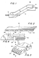
- escalator 10 includes an endless step loop 12 of interconnected step plates driven by appropriate machinery (not shown). At the top and bottom of the step loop combplate units 14 are provided, and form the entrance and exit platforms from which the users step onto and off of the escalator step plates.
- the combplates 14 typically include a serrated or grooved forward portion which mates with the corresponding grooves or serrations in the step plates and provides a continuous step surface and transition between the step plate and combplate.
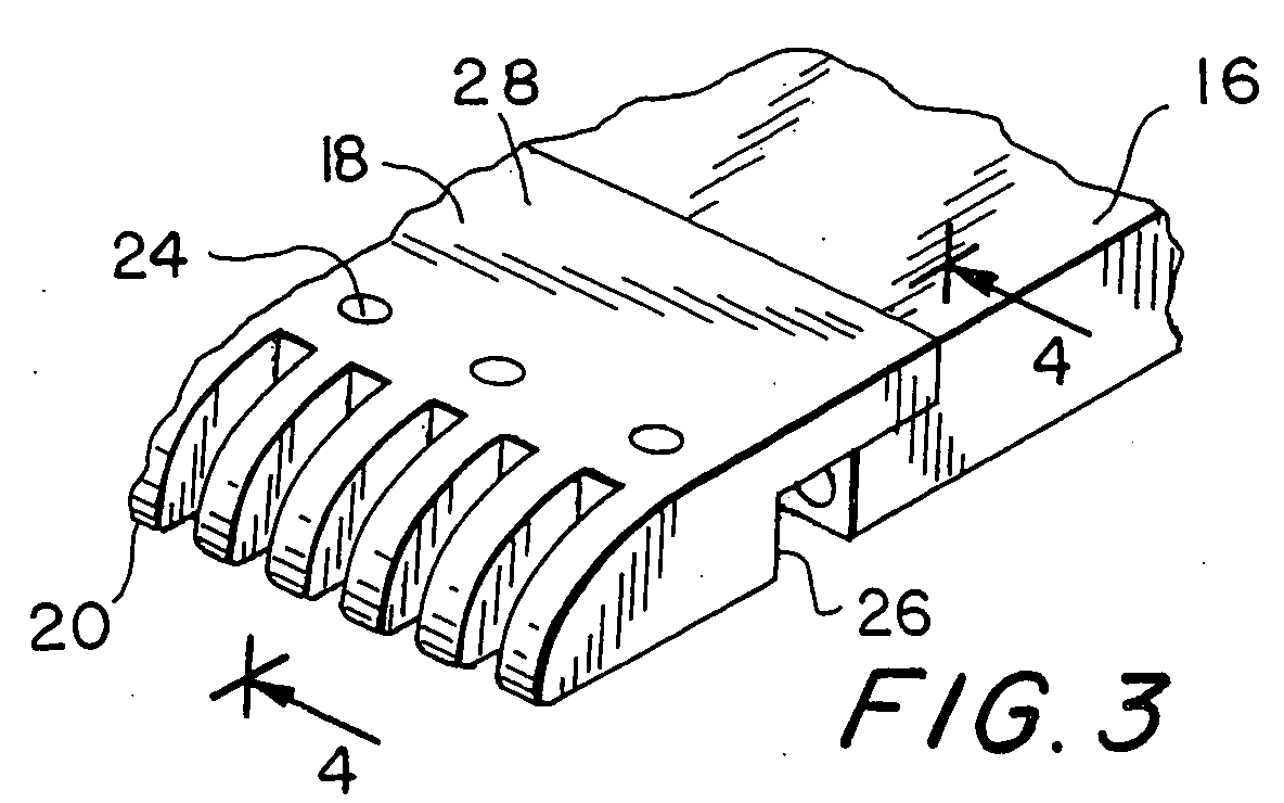
- the combplate in which the present invention is employed includes a main combplate portion 16 and a forward combteeth element 16, which bears the serrations 20 to mate with the grooves on the step plates.
- the forward combteeth plate portion 18 may be either rigidly or pivotly affixed to the main combplate 16, in manners known in the art. While not shown, both the forward combteeth element as well as the main combplate portion may be grooved or serrated along their top surfaces in a manner complementary to the grooves in the step plates and to provide an improved footing surface for the user.
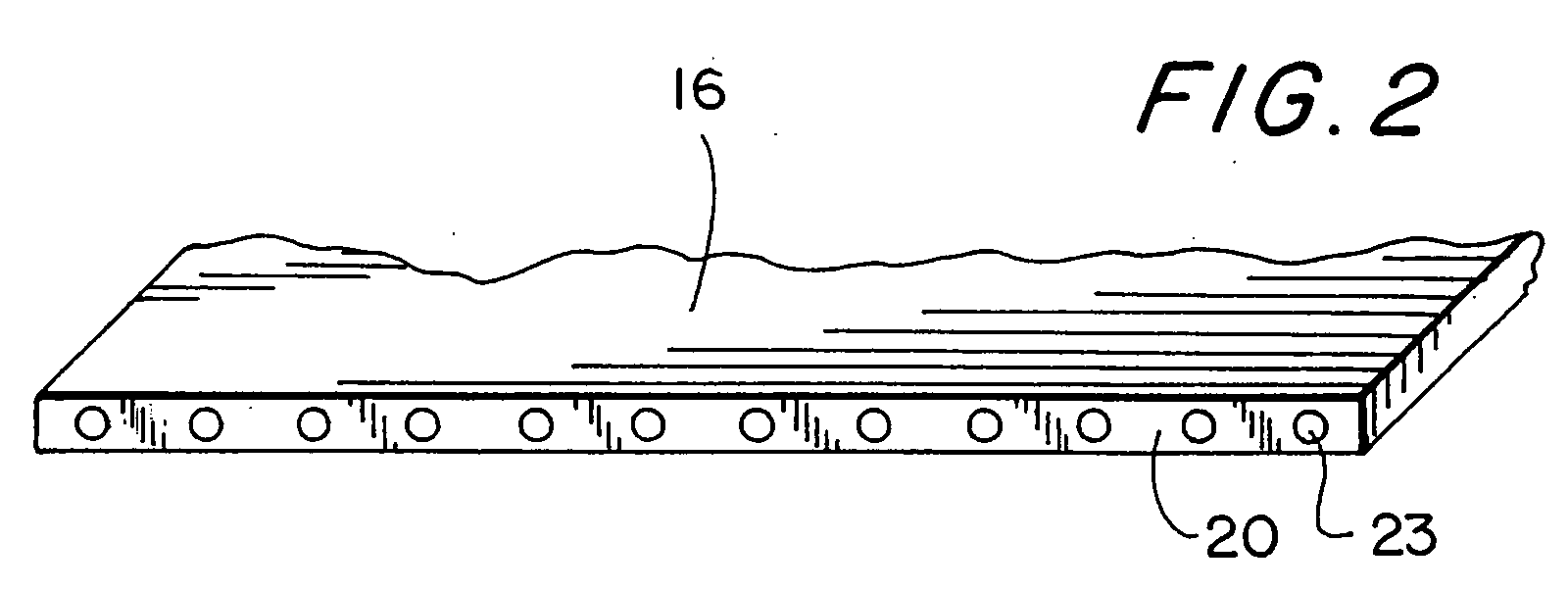
- forward edge 20 of main combplate portion 16 is provided with a plurality of light-generating means 22 in appropriately dimensioned accepting bores.
- the light-emitting means 22 may comprise a series of light-emitting diodes (LEDs).
- LEDs light-emitting diodes
- the light emitters 22 are in a spaced relationship along substantially the full width of the main combplate portion 16.
- the front surfaces of the emitters 22 are preferably flush with the forward edge 20.
- the main combplate portion 16 may be provided with appropriate internal channels or cavities (not shown) to accommodate the leads of the light emitters 20 and couple them to an appropriate drive circuit, also not shown.
- Forward combteeth element 18 is provided with a plurality of light pipes 24 running from the rear vertical edge 26 of the element which is adjacent to the forward edge 20 of main combplate portion 16 to an upper surface 28 of the element, such that the light transmitted thereby can be seen by users of the escalator.
- the light pipes 24 comprise a series of passageways or bores through the combteeth element, each of which is aligned with a corresponding one of the light emitters 22.
- the bores are filled with an appropriate light-transmitting compound or structure, such as an epoxy or polymer resin or a fiber optic bundle, chosen to transmit the light through the light pipe with minimal losses.
- a polymer compound is utilized, the end surfaces thereof being finished to be flush with the adjacent vertical and top surfaces 26, 28 of the combteeth element 18.
- the polymer can be either transparent or translucent, colorless or tinted.
- the light emitters 22 are preferably wired into at least two interleaved emitter groups, and are connected to drive circuitry that alternately illuminate the groups on a continuous basis.
- the light generated by the emitters is transmitted by the light pipes 24 to the upper surface of the combteeth element, where the alternating lights may be easily seen by the escalator user, whose attention is thus drawn to the forward end of the combplate and thus the intersection between the combplate and the moving escalator steps.
Landscapes
- Escalators And Moving Walkways (AREA)
- Polyesters Or Polycarbonates (AREA)
Abstract
Description
- The present invention relates to a new and improved apparatus for providing improved visibility to escalator surfaces and particularly to an escalator combplate.
- The act of entering and exiting an escalator can be of difficulty, particularly to the aged and infirm. Some of this difficulty can be attributed to a difficulty in perceiving the line of demarcation between the fixed step plate of the escalator and the continuously moving step system.
- The prior art teaches that an escalator combplate, which is that portion of the fixed step area which interacts with the moving steps, be provided with illumination to assist in identifying and delineating the combplate. Published European Patent Application 1 157 958 discloses an elevator combplate having a series of light-emitting diodes located behind a translucent comb. Because the light emitters are mounted vertically within the combplate, they must be of small dimension. Further, their mounting position provides limited area for interconnection. Also, their position subjects them to increased potential for damage.
- It is accordingly a purpose of the present invention to provide a new and improved illumination means for a combplate having increased durability and flexibility.
- In accordance with the foregoing and other purposes, objects and benefits, a combteeth illumination apparatus of the present invention comprises a series of spaced illumination means mounted to a forward edge of a main combplate element. A forward combteeth element, which engages with the escalator step, is provided with a plurality of light pipes extending between a first surface positioned adjacent the light-emitting means and a second end located on a common exposed surface of the combteeth element. The light pipes transmit light generated by the light emitters to the upper surface. The light emitters may be ganged into sets that may be alternately illuminated, the alternate illumination being able to be perceived at the combplate surface. The light emitters are activated whenever the escalator is operating.
- A fuller understanding of the present invention will be accomplished upon consideration of the following detailed disclosure of a preferred, but nonetheless illustrative embodiment of the invention, when reviewed in connection with the annexed drawings, wherein:
- Fig. 1 is an elevation view of an escalator employing the present invention;
- Fig. 2 is a perspective view of a forward edge of the main portion of the escalator combplate bearing the light-emitting means;
- Fig. 3 is a perspective view of a portion of the forward end of the combplate showing the forward combteeth element and the forward edge of the combplate main portion; and
- Fig. 4 is a partial section view taken along line 4-4 of Fig. 3.
-
- As seen in Fig. 1, escalator 10 includes an
endless step loop 12 of interconnected step plates driven by appropriate machinery (not shown). At the top and bottom of the steploop combplate units 14 are provided, and form the entrance and exit platforms from which the users step onto and off of the escalator step plates. As conventional escalator constructions typically utilize step plates that are of a laterally-grooved configuration, thecombplates 14 typically include a serrated or grooved forward portion which mates with the corresponding grooves or serrations in the step plates and provides a continuous step surface and transition between the step plate and combplate. - As shown in Fig. 3, the combplate in which the present invention is employed includes a
main combplate portion 16 and a forwardcombteeth element 16, which bears the serrations 20 to mate with the grooves on the step plates. The forwardcombteeth plate portion 18 may be either rigidly or pivotly affixed to themain combplate 16, in manners known in the art. While not shown, both the forward combteeth element as well as the main combplate portion may be grooved or serrated along their top surfaces in a manner complementary to the grooves in the step plates and to provide an improved footing surface for the user. - As seen in Fig. 2, forward edge 20 of
main combplate portion 16 is provided with a plurality of light-generating means 22 in appropriately dimensioned accepting bores. The light-emitting means 22 may comprise a series of light-emitting diodes (LEDs). Preferably, thelight emitters 22 are in a spaced relationship along substantially the full width of themain combplate portion 16. The front surfaces of theemitters 22 are preferably flush with the forward edge 20. Themain combplate portion 16 may be provided with appropriate internal channels or cavities (not shown) to accommodate the leads of the light emitters 20 and couple them to an appropriate drive circuit, also not shown. -
Forward combteeth element 18 is provided with a plurality oflight pipes 24 running from the rearvertical edge 26 of the element which is adjacent to the forward edge 20 ofmain combplate portion 16 to anupper surface 28 of the element, such that the light transmitted thereby can be seen by users of the escalator. Preferably, thelight pipes 24 comprise a series of passageways or bores through the combteeth element, each of which is aligned with a corresponding one of thelight emitters 22. The bores are filled with an appropriate light-transmitting compound or structure, such as an epoxy or polymer resin or a fiber optic bundle, chosen to transmit the light through the light pipe with minimal losses. In a preferred embodiment, a polymer compound is utilized, the end surfaces thereof being finished to be flush with the adjacent vertical andtop surfaces combteeth element 18. The polymer can be either transparent or translucent, colorless or tinted. - In operation, the
light emitters 22 are preferably wired into at least two interleaved emitter groups, and are connected to drive circuitry that alternately illuminate the groups on a continuous basis. The light generated by the emitters is transmitted by thelight pipes 24 to the upper surface of the combteeth element, where the alternating lights may be easily seen by the escalator user, whose attention is thus drawn to the forward end of the combplate and thus the intersection between the combplate and the moving escalator steps.
Claims (10)
- An illuminated escalator combplate, comprising:a main combplate portion having a depending front edge;light emitting means located along the front edge;a combteeth element extending forwardly from the main combplate element; andlight guide means in the combteeth element for directing light emitted by the light emitters to an upper surface of the combteeth element where the light can be seen by users of the escalator.
- The combplate of claim 1 wherein the light emitting means comprise a series of light emitters.
- The combplate of claim 1 wherein the light emitters are light emitting diodes.
- The combplate of claim 3 wherein the light emitting diodes are mounted in bores in the front edge and have front faces flush with the front edge.
- The combplate of claim 1, 2, or 3 wherein the light guide means extend between a vertical rear-facing surface of the combteeth element and the upper surface.
- The combplate of claim 1, 2, or 3 wherein the light guide means are a series of channels bearing a light-transmissive element.
- The combplate of claim 6, wherein the light-transmissive element is a transparent or translucent polymer.
- The combplate of claim 7, wherein the polymer is tinted.
- The combplate of claim 1, 2, or 3 wherein the light emitting means comprise at least two groups, each group being able to be illuminated independently.
- The combplate of claim 9 wherein the light emitting means of the groups are interleaved along the front edge.
Applications Claiming Priority (2)
| Application Number | Priority Date | Filing Date | Title |
|---|---|---|---|
| US124187 | 1980-02-25 | ||
| US10/124,187 US6530465B1 (en) | 2002-04-17 | 2002-04-17 | Illuminated escalator combplate |
Publications (2)
| Publication Number | Publication Date |
|---|---|
| EP1354839A1 true EP1354839A1 (en) | 2003-10-22 |
| EP1354839B1 EP1354839B1 (en) | 2011-01-19 |
Family
ID=22413323
Family Applications (1)
| Application Number | Title | Priority Date | Filing Date |
|---|---|---|---|
| EP03007570A Expired - Lifetime EP1354839B1 (en) | 2002-04-17 | 2003-04-02 | Illuminated escalator complate |
Country Status (5)
| Country | Link |
|---|---|
| US (1) | US6530465B1 (en) |
| EP (1) | EP1354839B1 (en) |
| AT (1) | ATE495996T1 (en) |
| CA (1) | CA2425720A1 (en) |
| DE (1) | DE60335763D1 (en) |
Families Citing this family (4)
| Publication number | Priority date | Publication date | Assignee | Title |
|---|---|---|---|---|
| US7080921B2 (en) * | 2004-02-13 | 2006-07-25 | Argent Electric, Inc. | Linear light using LEDs |
| DE102005033703A1 (en) * | 2005-07-19 | 2007-02-01 | Rolf Kistner | Combing segment for an escalator comprises visible warning sections arranged inward of the prong section on a visible surface of a base body and having warning elements |
| USD918521S1 (en) * | 2019-05-21 | 2021-05-04 | Inventio Ag | Escalator balustrade transition section |
| JP7106622B2 (en) * | 2020-12-16 | 2022-07-26 | 東芝エレベータ株式会社 | escalator |
Citations (1)
| Publication number | Priority date | Publication date | Assignee | Title |
|---|---|---|---|---|
| JPH0558579A (en) * | 1991-09-03 | 1993-03-09 | Hitachi Building Syst Eng & Service Co Ltd | Passenger conveyer |
Family Cites Families (5)
| Publication number | Priority date | Publication date | Assignee | Title |
|---|---|---|---|---|
| KR900002280Y1 (en) * | 1985-04-23 | 1990-03-17 | 미쓰비시전기주식회사 | Passenger conveyor device |
| JP2517776B2 (en) * | 1990-04-12 | 1996-07-24 | 株式会社日立製作所 | Escalator |
| ATE180463T1 (en) * | 1994-03-09 | 1999-06-15 | Inventio Ag | LIGHTING DEVICE WITH LIGHT GUIDES FOR ESCALATORS OR MOVING WALKWAYS |
| JPH1045363A (en) * | 1996-07-31 | 1998-02-17 | Toshiba Elevator Technos Kk | Passenger conveyor |
| EP1157958A1 (en) * | 2000-05-15 | 2001-11-28 | Inventio Ag | Escalator or moving walkway with illuminated combplate |
-
2002
- 2002-04-17 US US10/124,187 patent/US6530465B1/en not_active Expired - Lifetime
-
2003
- 2003-04-02 EP EP03007570A patent/EP1354839B1/en not_active Expired - Lifetime
- 2003-04-02 AT AT03007570T patent/ATE495996T1/en active
- 2003-04-02 DE DE60335763T patent/DE60335763D1/en not_active Expired - Lifetime
- 2003-04-15 CA CA002425720A patent/CA2425720A1/en not_active Abandoned
Patent Citations (1)
| Publication number | Priority date | Publication date | Assignee | Title |
|---|---|---|---|---|
| JPH0558579A (en) * | 1991-09-03 | 1993-03-09 | Hitachi Building Syst Eng & Service Co Ltd | Passenger conveyer |
Non-Patent Citations (1)
| Title |
|---|
| PATENT ABSTRACTS OF JAPAN vol. 017, no. 370 (M - 1444) 13 July 1993 (1993-07-13) * |
Also Published As
| Publication number | Publication date |
|---|---|
| DE60335763D1 (en) | 2011-03-03 |
| ATE495996T1 (en) | 2011-02-15 |
| US6530465B1 (en) | 2003-03-11 |
| CA2425720A1 (en) | 2003-10-17 |
| EP1354839B1 (en) | 2011-01-19 |
Similar Documents
| Publication | Publication Date | Title |
|---|---|---|
| CN1103314C (en) | Lighting device for system used for conveying people | |
| EP1103759A3 (en) | Full-color light source unit | |
| EP1395064A3 (en) | Illumination apparatus and projector display apparatus | |
| US20130308336A1 (en) | Flat and thin led-based luminaire | |
| EP1354839B1 (en) | Illuminated escalator complate | |
| CN101048334A (en) | Elevator installation with light modules on sill profiles | |
| US5613758A (en) | Illuminating device with optical conductors for escalators or moving walkways | |
| WO2003077004A9 (en) | Apparatus, methods and articles of manufacture for a co-extruded light pipe | |
| JP7106622B2 (en) | escalator | |
| WO2008080423A1 (en) | People conveyor with brush guard lighting | |
| ATE300496T1 (en) | DEDICTION DEVICE FOR ESCALATOR OR MOVING WALKWAY | |
| JP7263137B2 (en) | lighting handrail | |
| JPH08202300A (en) | Light emission display device | |
| JP7630386B2 (en) | Passenger conveyor | |
| JP2020200162A (en) | Passenger conveyor | |
| JPH09249373A (en) | Moving staircase display device | |
| EP0785446A3 (en) | Optical correction layer for a light emitting apparatus | |
| GB2185503A (en) | Illuminated step edging | |
| JP2006131379A (en) | Man conveyor and footstep | |
| JP7529115B1 (en) | Man Conveyor | |
| CN100363961C (en) | Luminous signs | |
| JPH07209519A (en) | road sign | |
| EP1403581A2 (en) | Lighting system for complementary building elements | |
| CN120062577A (en) | Light guide element, car lamp and vehicle | |
| US20030174513A1 (en) | Luminaire having an optical conductor and a plurality of light sources |
Legal Events
| Date | Code | Title | Description |
|---|---|---|---|
| PUAI | Public reference made under article 153(3) epc to a published international application that has entered the european phase |
Free format text: ORIGINAL CODE: 0009012 |
|
| AK | Designated contracting states |
Kind code of ref document: A1 Designated state(s): AT BE BG CH CY CZ DE DK EE ES FI FR GB GR HU IE IT LI LU MC NL PT RO SE SI SK TR |
|
| AX | Request for extension of the european patent |
Extension state: AL LT LV MK |
|
| 17P | Request for examination filed |
Effective date: 20040413 |
|
| AKX | Designation fees paid |
Designated state(s): AT CH DE FR GB LI |
|
| GRAP | Despatch of communication of intention to grant a patent |
Free format text: ORIGINAL CODE: EPIDOSNIGR1 |
|
| GRAS | Grant fee paid |
Free format text: ORIGINAL CODE: EPIDOSNIGR3 |
|
| GRAA | (expected) grant |
Free format text: ORIGINAL CODE: 0009210 |
|
| AK | Designated contracting states |
Kind code of ref document: B1 Designated state(s): AT CH DE FR GB LI |
|
| REG | Reference to a national code |
Ref country code: GB Ref legal event code: FG4D |
|
| REG | Reference to a national code |
Ref country code: CH Ref legal event code: EP |
|
| RTI2 | Title (correction) |
Free format text: ILLUMINATED ESCALATOR COMBPLATE |
|
| REF | Corresponds to: |
Ref document number: 60335763 Country of ref document: DE Date of ref document: 20110303 Kind code of ref document: P |
|
| REG | Reference to a national code |
Ref country code: DE Ref legal event code: R096 Ref document number: 60335763 Country of ref document: DE Effective date: 20110303 |
|
| PLBE | No opposition filed within time limit |
Free format text: ORIGINAL CODE: 0009261 |
|
| STAA | Information on the status of an ep patent application or granted ep patent |
Free format text: STATUS: NO OPPOSITION FILED WITHIN TIME LIMIT |
|
| 26N | No opposition filed |
Effective date: 20111020 |
|
| REG | Reference to a national code |
Ref country code: DE Ref legal event code: R097 Ref document number: 60335763 Country of ref document: DE Effective date: 20111020 |
|
| PGFP | Annual fee paid to national office [announced via postgrant information from national office to epo] |
Ref country code: CH Payment date: 20150428 Year of fee payment: 13 |
|
| PGFP | Annual fee paid to national office [announced via postgrant information from national office to epo] |
Ref country code: AT Payment date: 20150421 Year of fee payment: 13 |
|
| REG | Reference to a national code |
Ref country code: FR Ref legal event code: PLFP Year of fee payment: 14 |
|
| PGFP | Annual fee paid to national office [announced via postgrant information from national office to epo] |
Ref country code: DE Payment date: 20160421 Year of fee payment: 14 Ref country code: GB Payment date: 20160421 Year of fee payment: 14 |
|
| PGFP | Annual fee paid to national office [announced via postgrant information from national office to epo] |
Ref country code: FR Payment date: 20160421 Year of fee payment: 14 |
|
| REG | Reference to a national code |
Ref country code: CH Ref legal event code: PL |
|
| REG | Reference to a national code |
Ref country code: AT Ref legal event code: MM01 Ref document number: 495996 Country of ref document: AT Kind code of ref document: T Effective date: 20160402 |
|
| PG25 | Lapsed in a contracting state [announced via postgrant information from national office to epo] |
Ref country code: CH Free format text: LAPSE BECAUSE OF NON-PAYMENT OF DUE FEES Effective date: 20160430 Ref country code: LI Free format text: LAPSE BECAUSE OF NON-PAYMENT OF DUE FEES Effective date: 20160430 |
|
| PG25 | Lapsed in a contracting state [announced via postgrant information from national office to epo] |
Ref country code: AT Free format text: LAPSE BECAUSE OF NON-PAYMENT OF DUE FEES Effective date: 20160402 |
|
| REG | Reference to a national code |
Ref country code: DE Ref legal event code: R119 Ref document number: 60335763 Country of ref document: DE |
|
| GBPC | Gb: european patent ceased through non-payment of renewal fee |
Effective date: 20170402 |
|
| REG | Reference to a national code |
Ref country code: FR Ref legal event code: ST Effective date: 20171229 |
|
| PG25 | Lapsed in a contracting state [announced via postgrant information from national office to epo] |
Ref country code: FR Free format text: LAPSE BECAUSE OF NON-PAYMENT OF DUE FEES Effective date: 20170502 Ref country code: DE Free format text: LAPSE BECAUSE OF NON-PAYMENT OF DUE FEES Effective date: 20171103 |
|
| PG25 | Lapsed in a contracting state [announced via postgrant information from national office to epo] |
Ref country code: GB Free format text: LAPSE BECAUSE OF NON-PAYMENT OF DUE FEES Effective date: 20170402 |