EP1354662A1 - Friction welding apparatus - Google Patents
Friction welding apparatus Download PDFInfo
- Publication number
- EP1354662A1 EP1354662A1 EP03290806A EP03290806A EP1354662A1 EP 1354662 A1 EP1354662 A1 EP 1354662A1 EP 03290806 A EP03290806 A EP 03290806A EP 03290806 A EP03290806 A EP 03290806A EP 1354662 A1 EP1354662 A1 EP 1354662A1
- Authority
- EP
- European Patent Office
- Prior art keywords
- workpieces
- pressing
- burrs
- rotary
- welding apparatus
- Prior art date
- Legal status (The legal status is an assumption and is not a legal conclusion. Google has not performed a legal analysis and makes no representation as to the accuracy of the status listed.)
- Withdrawn
Links
Images


Classifications
-
- B—PERFORMING OPERATIONS; TRANSPORTING
- B23—MACHINE TOOLS; METAL-WORKING NOT OTHERWISE PROVIDED FOR
- B23K—SOLDERING OR UNSOLDERING; WELDING; CLADDING OR PLATING BY SOLDERING OR WELDING; CUTTING BY APPLYING HEAT LOCALLY, e.g. FLAME CUTTING; WORKING BY LASER BEAM
- B23K20/00—Non-electric welding by applying impact or other pressure, with or without the application of heat, e.g. cladding or plating
- B23K20/12—Non-electric welding by applying impact or other pressure, with or without the application of heat, e.g. cladding or plating the heat being generated by friction; Friction welding
- B23K20/1205—Non-electric welding by applying impact or other pressure, with or without the application of heat, e.g. cladding or plating the heat being generated by friction; Friction welding using translation movement
-
- B—PERFORMING OPERATIONS; TRANSPORTING
- B23—MACHINE TOOLS; METAL-WORKING NOT OTHERWISE PROVIDED FOR
- B23K—SOLDERING OR UNSOLDERING; WELDING; CLADDING OR PLATING BY SOLDERING OR WELDING; CUTTING BY APPLYING HEAT LOCALLY, e.g. FLAME CUTTING; WORKING BY LASER BEAM
- B23K37/00—Auxiliary devices or processes, not specially adapted to a procedure covered by only one of the preceding main groups
- B23K37/06—Auxiliary devices or processes, not specially adapted to a procedure covered by only one of the preceding main groups for positioning the molten material, e.g. confining it to a desired area
Definitions
- the present invention relates to a friction welding apparatus for welding between different materials such as stems of a poppet valve.
- valve head is made of austenite heat-resistant steel
- valve stem is made of martensite heat-resistant steel. They are welded to each other.
- the friction welding apparatus “A” comprises a rotary holder 2 fixed on a base 1, and a fixing holder 3 which moves from side to side reciprocally on the base 1 by a hydraulic cylinder (not shown).
- a collet-type rotary chuck 2a and a fixing chuck 3a are mounted on opposing surfaces of the holders 2 and 3 respectively.
- a stem material 4 for a poppet valve is held by the rotary chuck 2a, and a head material 5 is held by the fixing chuck 3a so that opposing ends of the materials 4,5 may project at a predetermined distance. Then, while the rotary chuck 2a is rotated at high speed, the fixing holder 3 is moved rightward, and the end faces of the materials 4,5 are pressed under suitable pressure. The end faces are melted by friction heat, so that the materials 4,5 are welded to each other.
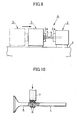
- C-sectioned weld burrs 6,6 are formed on welded portion as shown in Fig. 10.
- the burrs 6 are removed by a grinding wheel 7, portions which are adhered on the outer circumferential surface of the stem remain, and are put between the grinding wheel 7 and the stem, thereby damaging the outer circumferential surface of the stem.
- axial lengths of the burrs 6 are relatively larger, which requires use of the large-width grinding wheel 7 to result in increase in cost.
- the burrs 6 are removed by a press as shown in Fig. 11.
- the burrs 6 are supported by a sharing blade 8a of a circular die 8 which is dividable right and left, and strongly pressed on the top by a punch 9.
- the burrs 6 are removed by punching, but slightly larger stepped portions are formed on the outer circumferential surface of bound portion as shown in Fig. 12.
- the internal diameter of the blade 8a is determined equal to the external diameter of the stem, the diameter of the bound portion may become smaller than the external diameter when the burrs 6 are cut off by punching.
- the internal diameter of the blade 8a is set to a diameter slightly larger than the axial diameter, which generates the stepped portions of the bound portion.
- the stepped portions of the bound portion must be cut off using a cutting tool or a grinding wheel, thereby increasing the number of working steps to cause decrease in productivity.
- a friction welding apparatus comprising a rotary holder; a fixing holder which faces said rotary holder axially; a rotary chuck provided on said rotary holder; a fixing chuck provided on said fixing holder, a first workpiece held in a rotary chuck being rotated and pressed towards a second workpiece held in said fixing chuck so that the first workpiece may be bound with the second workpiece with friction heat; and pressing means having pressing surfaces which faces each other axially via a clearance in which weld burrs generated at a bound portion of the first and second workpieces can be inserted between said pressing surfaces, thereby preventing the burrs from expanding axially.
- FIGs. 1 and 2 illustrate the first embodiment of the present invention.
- a friction welding apparatus 10 comprises a rotary holder 2 and a fixing holder 3 which have a rotary chuck 2a and a fixing chuck 3a respectively.
- Annular pressing portions 11,11 having axial bores 11a,11a are provided on the rotary and fixing chucks 2a,3a to expand and shrink radially together with the chucks 2a,3a.
- the annular pressing portions 11,11 are separable into a number of divisions circumferentially.
- the materials 4,5 are held between the rotary and fixing chucks 2a and 3a so that the opposing ends may project from pressing surfaces 11b,11b of the blocks 11,11.
- the materials 4,5 are slightly longer than what are welded to form burrs during welding.
- the engaged surfaces are welded to generate weld burrs 6,6.
- a clearance between the pressing surfaces 11b,11b of the pressing portions 11,11 becomes smaller.
- the burrs 6 are prevented from expanding axially and enlarged radially perpendicular to the axis in the clearance between the pressing portions 11,11.
- the axial lengths of the burrs 6 become smaller, and the burrs 6 can be easily removed without damaging the outer circumferential surface of the stem using a smaller-width inexpensive grinding wheel 7 as shown in Fig. 3. Also the burrs 6 can be easily removed by a cutting tool.
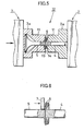
- Figs. 4 and 5 illustrate the second embodiment of a friction welding apparatus 12 of the present invention, in which the pressing surfaces of pressing portions 11,11 are inclined to fit in shape with each other, which is different from the foregoing embodiment.
- a concave surface 13 is formed, and at the end of the right-hand pressing portion 11, a convex surface 14 is formed.
- weld burrs 6,6 are bent by the inclined surfaces 13,14 between the pressing portions 11 and 11 and extended radially as shown in Fig. 5.
- the burrs 6 are prevented from expanding axially as well as the first embodiment.
- the burrs 6 can be easily cut off by a grinding wheel or a cutting tool.
- a narrower grinding wheel 7 is moved along the outer circumferential surface, so that the bases of the burrs 6 can be cut off as rings.
- the inclined surfaces 13,14 of the pressing portions 11 may be oppositely inclined so that the burrs 6 may be inclined leftward.
- Figs. 7 and 8 illustrate the third embodiment of the present invention, in which means for pressing burrs are separately provided from chucks 2a,3a.
- a pair of pressing members 17,17 each consisting of semi-circular disc which has a semi-circular groove 16 slightly larger than radii of materials 4,5.
- the pressing members 17 are connected to reciprocating means such as a hydraulic cylinder (not shown), so that the members can go toward and away from a connected portion of the materials 4,5.
- the pressing members 17,17 goes towards the materials 4,5.
- the materials 4,5 are engaged with each other, so that generated weld burrs 6,6 are inserted in the semi-circular grooves 15,15 and pressed, so that the materials 4,5 cannot be expanded axially.
- the present invention may be applied to binding of ordinary workpieces.
Landscapes
- Engineering & Computer Science (AREA)
- Mechanical Engineering (AREA)
- Physics & Mathematics (AREA)
- Optics & Photonics (AREA)
- Pressure Welding/Diffusion-Bonding (AREA)
Abstract
Two workpieces (4,5) are frictionally welded by a friction welding
apparatus (10) which comprises a fixing holder (3) and a rotary holder (2). One
of the workpieces are held by a fixing chuck (3a) provided on the fixing
holder (3), while the other is held by a rotary chuck (2a) provided on the rotary
holder (2). Pressing portions (11) are formed on opposing surfaces of the
chucks. When the work pieces (4,5) are pressed by the holders (2,3) and
welded to each other with friction heat, burrs (6,6) generated around a
bound portion of the workpieces are prevented by the pressing
portions from expanding axially of the workpieces
Description
- The present invention relates to a friction welding apparatus for welding between different materials such as stems of a poppet valve.
- In poppet valves which are used in an internal combustion engine, a valve head is made of austenite heat-resistant steel, and a valve stem is made of martensite heat-resistant steel. They are welded to each other.
- Stems of such a valve are welded to each other using friction welding apparatus as shown in Fig. 9. The friction welding apparatus "A" comprises a
rotary holder 2 fixed on a base 1, and afixing holder 3 which moves from side to side reciprocally on the base 1 by a hydraulic cylinder (not shown). A collet-type rotary chuck 2a and afixing chuck 3a are mounted on opposing surfaces of theholders - To weld workpieces to each other, a
stem material 4 for a poppet valve is held by therotary chuck 2a, and ahead material 5 is held by thefixing chuck 3a so that opposing ends of thematerials rotary chuck 2a is rotated at high speed, thefixing holder 3 is moved rightward, and the end faces of thematerials materials - When the
materials weld burrs burrs 6 are removed by agrinding wheel 7, portions which are adhered on the outer circumferential surface of the stem remain, and are put between thegrinding wheel 7 and the stem, thereby damaging the outer circumferential surface of the stem. Furthermore, axial lengths of theburrs 6 are relatively larger, which requires use of the large-width grinding wheel 7 to result in increase in cost. - To solve the disadvantage, the
burrs 6 are removed by a press as shown in Fig. 11. Theburrs 6 are supported by a sharingblade 8a of acircular die 8 which is dividable right and left, and strongly pressed on the top by apunch 9. Thus, theburrs 6 are removed by punching, but slightly larger stepped portions are formed on the outer circumferential surface of bound portion as shown in Fig. 12. If the internal diameter of theblade 8a is determined equal to the external diameter of the stem, the diameter of the bound portion may become smaller than the external diameter when theburrs 6 are cut off by punching. To prevent it, the internal diameter of theblade 8a is set to a diameter slightly larger than the axial diameter, which generates the stepped portions of the bound portion. - The stepped portions of the bound portion must be cut off using a cutting tool or a grinding wheel, thereby increasing the number of working steps to cause decrease in productivity.
- In view of the disadvantages, it is an object of the present invention to provide a friction welding apparatus to prevent weld burrs from expanding axially and to cut them off.
- To achieve the object, according to the present invention, there is provided a friction welding apparatus comprising a rotary holder; a fixing holder which faces said rotary holder axially; a rotary chuck provided on said rotary holder; a fixing chuck provided on said fixing holder, a first workpiece held in a rotary chuck being rotated and pressed towards a second workpiece held in said fixing chuck so that the first workpiece may be bound with the second workpiece with friction heat; and pressing means having pressing surfaces which faces each other axially via a clearance in which weld burrs generated at a bound portion of the first and second workpieces can be inserted between said pressing surfaces, thereby preventing the burrs from expanding axially.
- The features and advantages of the present invention will become more apparent from the following description with respect to embodiments as shown in appended drawings wherein:
- Fig. 1 is a horizontal sectional plan view of the first embodiment of a friction welding apparatus according to the present invention before welding of workpieces;
- Fig. 2 is a horizontal sectional plan view when the workpieces are welded;
- Fig. 3 is a plan view which illustrates how to cut off burrs formed by the apparatus in Fig. 1;
- Fig. 4 is a horizontal sectional plan view of the second embodiment of an apparatus before welding of workpieces;
- Fig. 5 is a horizontal sectional plan view when the workpieces are welded;
- Fig. 6 is a plan view which illustrates how to cut off weld burrs formed in the second embodiment;
- Fig. 7 is a horizontal sectional plan view of the third embodiment of an apparatus according to the present invention before welding of workpieces;
- Fig. 8 is a horizontal sectional plan view when the workpieces are welded;
- Fig. 9 is a side elevational view which illustrates how to weld of workpieces in a known friction welding apparatus;
- Fig. 10 is a plan view which illustrates how to cut off weld burrs formed in a known apparatus;
- Fig. 11 is a front elevational view which illustrates how to cut off weld burrs in another known apparatus; and
- Fig. 12 is a front elevational view which illustrates a shape of a welded portion of workpieces after weld burrs are cut off.
-
- Figs. 1 and 2 illustrate the first embodiment of the present invention. A
friction welding apparatus 10 comprises arotary holder 2 and afixing holder 3 which have arotary chuck 2a and afixing chuck 3a respectively. Annular pressingportions axial bores chucks chucks pressing portions - To bind a
stem material 4 with ahead material 5 of a poppet valve using thefriction welding apparatus 10, as shown in Fig. 1, thematerials fixing chucks pressing surfaces blocks materials - Then, as shown in Fig. 2, while the
rotary chuck 3 is rotated at high speed, thefixing holder 3 is moved rightward, so that the axial end of thehead material 5 is engaged on the axial end of thestem material 4 and pressed at suitable pressure. - The engaged surfaces are welded to generate
weld burrs pressing surfaces pressing portions burrs 6 are prevented from expanding axially and enlarged radially perpendicular to the axis in the clearance between thepressing portions - The axial lengths of the
burrs 6 become smaller, and theburrs 6 can be easily removed without damaging the outer circumferential surface of the stem using a smaller-widthinexpensive grinding wheel 7 as shown in Fig. 3. Also theburrs 6 can be easily removed by a cutting tool. - Figs. 4 and 5 illustrate the second embodiment of a
friction welding apparatus 12 of the present invention, in which the pressing surfaces ofpressing portions - At the end of the left-hand pressing
portion 11, aconcave surface 13 is formed, and at the end of the right-hand pressingportion 11, aconvex surface 14 is formed. - By the
friction welding apparatus 12 having thepressing portions stem material 4 and the head meterial 5 are bound with each other at the ends according to a method similar to the first embodiment,weld burrs inclined surfaces pressing portions - In the second embodiment, the
burrs 6 are prevented from expanding axially as well as the first embodiment. Thus, theburrs 6 can be easily cut off by a grinding wheel or a cutting tool. - Owing to the inclination of the
burrs 6, as shown in Fig. 6, anarrower grinding wheel 7 is moved along the outer circumferential surface, so that the bases of theburrs 6 can be cut off as rings. - Accordingly, compared with cutting off the
whole burrs 6, working time for cutting off the burrs can be significantly shortened. In this embodiment, theinclined surfaces pressing portions 11 may be oppositely inclined so that theburrs 6 may be inclined leftward. - Figs. 7 and 8 illustrate the third embodiment of the present invention, in which means for pressing burrs are separately provided from
chucks chucks members semi-circular groove 16 slightly larger than radii ofmaterials pressing members 17 are connected to reciprocating means such as a hydraulic cylinder (not shown), so that the members can go toward and away from a connected portion of thematerials - As shown in Fig. 8, the
pressing members materials pressing members 17 is engaged on or placed closer to thematerials materials weld burrs semi-circular grooves materials - Other than binding of the stems of a poppet valve, the present invention may be applied to binding of ordinary workpieces.
- The foregoing merely relate to embodiments of the invention. Various changes and modifications may be made by a person skilled in the art without departing from the scope of claims wherein:
Claims (4)
- A friction welding apparatus comprising:a rotary holder;a fixing holder which faces said rotary holder axially;a rotary chuck provided on said rotary holder;a fixing chuck provided on said fixing holder, a first workpiece held in a rotary chuck being rotated and pressed towards a second workpiece held in said fixing chuck so that the first workpiece may be bound with the second workpiece with friction heat; andpressing means having pressing surfaces which faces each other axially via a clearance in which weld burrs generated at a bound portion of the first and second workpieces can be inserted between said pressing surfaces, thereby preventing the burrs from expanding axially.
- A friction welding apparatus as claimed in claim 1 wherein the pressing means comprises pressing portions integrally formed on opposing surfaces of the fixing and rotary chucks.
- A friction welding apparatus as claimed in claim 2 wherein one of the pressing surfaces is formed as convex, while the other is formed as concave to fit in shape with each other.
- A friction welding apparatus as claimed in claim 1 wherein said pressing means comprise a pair of semi-spherical pressing members provided on both sides of an axis of the workpieces so as to go towards and away from the bound portion of the workpieces, each of said pair of pressing members having a semi-spherical groove in which the weld burrs can be inserted, and an inside semi-spherical recess larger than radii of the workpieces.
Applications Claiming Priority (2)
| Application Number | Priority Date | Filing Date | Title |
|---|---|---|---|
| JP2002117025 | 2002-04-19 | ||
| JP2002117025A JP2003311437A (en) | 2002-04-19 | 2002-04-19 | Friction welding equipment |
Publications (1)
| Publication Number | Publication Date |
|---|---|
| EP1354662A1 true EP1354662A1 (en) | 2003-10-22 |
Family
ID=28672673
Family Applications (1)
| Application Number | Title | Priority Date | Filing Date |
|---|---|---|---|
| EP03290806A Withdrawn EP1354662A1 (en) | 2002-04-19 | 2003-03-31 | Friction welding apparatus |
Country Status (5)
| Country | Link |
|---|---|
| US (1) | US20030197047A1 (en) |
| EP (1) | EP1354662A1 (en) |
| JP (1) | JP2003311437A (en) |
| KR (1) | KR20030083574A (en) |
| CN (1) | CN1451509A (en) |
Cited By (4)
| Publication number | Priority date | Publication date | Assignee | Title |
|---|---|---|---|---|
| US8393521B1 (en) | 2011-12-20 | 2013-03-12 | Caterpillar Inc. | Flash ring separator |
| EP2960004A1 (en) * | 2014-05-22 | 2015-12-30 | ArvinMeritor Technology, LLC | System and method of friction welding a workpiece |
| WO2018024718A1 (en) * | 2016-08-01 | 2018-02-08 | Kuka Industries Gmbh | Combined friction-welding and shearing off of the weld bead |
| EP2650075B1 (en) * | 2010-11-25 | 2022-01-19 | Nittan Valve Co., Ltd. | Deburring device for friction welding machine |
Families Citing this family (17)
| Publication number | Priority date | Publication date | Assignee | Title |
|---|---|---|---|---|
| KR101349287B1 (en) * | 2007-10-30 | 2014-01-16 | 재단법인 포항산업과학연구원 | Method of manufacturing metal sheet |
| CN101598654B (en) * | 2008-11-21 | 2010-12-01 | 西北工业大学 | Physical simulation method for plastic deformation of friction welding joint |
| CN102896433A (en) * | 2012-10-17 | 2013-01-30 | 国家电网公司 | Automatic welding method of columnar piece |
| CN104014928A (en) * | 2014-06-19 | 2014-09-03 | 西安特种设备检验检测院 | Dissimilar steel welding method for martensite heat-resisting steel and austenitic heat-resisting steel |
| DE202014105434U1 (en) * | 2014-11-12 | 2016-02-15 | Kuka Systems Gmbh | Pressure welding apparatus |
| CN104439690A (en) * | 2014-11-24 | 2015-03-25 | 福斯流体控制(苏州)有限公司 | Pressure welding method applied to valve rod |
| CN107538129B (en) * | 2016-06-29 | 2020-06-23 | 中国航空制造技术研究院 | Backfill formula friction stir spot welding post-weld sizing separator |
| US11536311B2 (en) * | 2017-03-07 | 2022-12-27 | Neapco Intellectual Property Holdings, Llc | Integrated post-weld knurling process and device for performing the same |
| JP6951128B2 (en) * | 2017-06-12 | 2021-10-20 | 日本スピンドル製造株式会社 | Member joining method and rotary plastic working equipment |
| CN109175672B (en) * | 2018-11-05 | 2020-08-04 | 中国航空制造技术研究院 | Flash deformation control device and method in linear friction welding process |
| KR102084949B1 (en) * | 2019-04-30 | 2020-03-05 | 에이에프더블류 주식회사 | Manufacturing method of a bus bar |
| JP7261678B2 (en) * | 2019-07-04 | 2023-04-20 | シチズン時計株式会社 | Machine tools and processing methods |
| DE112020004580T5 (en) * | 2019-09-26 | 2022-06-09 | Hitachi Astemo, Ltd. | Method of making a bar |
| CN111408912B (en) * | 2020-05-14 | 2021-08-20 | 中国兵器工业第五九研究所 | Preparation method and clamping tool for small-diameter narrow-gap thin-wall multi-blade component |
| CN113843497B (en) * | 2021-09-23 | 2022-12-20 | 无锡亨通特种合金制造有限公司 | Welding seam processing system for friction welding of thin-wall pipe |
| CN114043068B (en) * | 2021-10-22 | 2023-02-28 | 中国航空制造技术研究院 | Linear friction welding joint flash forming control method |
| CN114433998B (en) * | 2022-03-25 | 2023-04-14 | 南通重矿金属新材料有限公司 | Stirring friction and extrusion compounding device for metal material |
Citations (6)
| Publication number | Priority date | Publication date | Assignee | Title |
|---|---|---|---|---|
| US3259969A (en) * | 1963-01-22 | 1966-07-12 | Central Cable Corp | Method of making butt welded joints |
| US3452914A (en) * | 1962-07-09 | 1969-07-01 | Caterpillar Tractor Co | Apparatus for controlling flash during friction bonding |
| FR2096924A7 (en) * | 1970-07-16 | 1972-03-03 | Caterpillar Tractor Co | |
| US3853258A (en) * | 1972-07-17 | 1974-12-10 | Textron Inc | Flash removal apparatus for a friction welding operation |
| JPS6160283A (en) * | 1984-08-31 | 1986-03-27 | Fuji Valve Kk | Working of engine valve |
| JPS63264285A (en) * | 1987-04-23 | 1988-11-01 | Mazda Motor Corp | Friction welding method |
Family Cites Families (5)
| Publication number | Priority date | Publication date | Assignee | Title |
|---|---|---|---|---|
| US4079491A (en) * | 1976-02-06 | 1978-03-21 | Sargent Industries | Method and apparatus for forming a valve seat by inertia welding |
| JPH0818151B2 (en) * | 1988-11-11 | 1996-02-28 | 大同特殊鋼株式会社 | Joining method and joining part of Ti-Al alloy and structural steel |
| EP0898055B1 (en) * | 1997-08-19 | 2002-05-08 | TRW Deutschland GmbH | Hollow valve for internal combustion engine |
| US6691910B2 (en) * | 2000-12-08 | 2004-02-17 | Fuji Oozx, Inc. | Method of joining different metal materials by friction welding |
| JP4178758B2 (en) * | 2001-02-08 | 2008-11-12 | 株式会社豊田自動織機 | Joint structure of valve seat |
-
2002
- 2002-04-19 JP JP2002117025A patent/JP2003311437A/en active Pending
-
2003
- 2003-02-10 US US10/361,227 patent/US20030197047A1/en not_active Abandoned
- 2003-02-13 CN CN03103850A patent/CN1451509A/en active Pending
- 2003-02-27 KR KR10-2003-0012289A patent/KR20030083574A/en not_active Application Discontinuation
- 2003-03-31 EP EP03290806A patent/EP1354662A1/en not_active Withdrawn
Patent Citations (6)
| Publication number | Priority date | Publication date | Assignee | Title |
|---|---|---|---|---|
| US3452914A (en) * | 1962-07-09 | 1969-07-01 | Caterpillar Tractor Co | Apparatus for controlling flash during friction bonding |
| US3259969A (en) * | 1963-01-22 | 1966-07-12 | Central Cable Corp | Method of making butt welded joints |
| FR2096924A7 (en) * | 1970-07-16 | 1972-03-03 | Caterpillar Tractor Co | |
| US3853258A (en) * | 1972-07-17 | 1974-12-10 | Textron Inc | Flash removal apparatus for a friction welding operation |
| JPS6160283A (en) * | 1984-08-31 | 1986-03-27 | Fuji Valve Kk | Working of engine valve |
| JPS63264285A (en) * | 1987-04-23 | 1988-11-01 | Mazda Motor Corp | Friction welding method |
Non-Patent Citations (2)
| Title |
|---|
| PATENT ABSTRACTS OF JAPAN vol. 010, no. 222 (M - 504) 2 August 1986 (1986-08-02) * |
| PATENT ABSTRACTS OF JAPAN vol. 013, no. 060 (M - 796) 10 February 1989 (1989-02-10) * |
Cited By (5)
| Publication number | Priority date | Publication date | Assignee | Title |
|---|---|---|---|---|
| EP2650075B1 (en) * | 2010-11-25 | 2022-01-19 | Nittan Valve Co., Ltd. | Deburring device for friction welding machine |
| US8393521B1 (en) | 2011-12-20 | 2013-03-12 | Caterpillar Inc. | Flash ring separator |
| EP2960004A1 (en) * | 2014-05-22 | 2015-12-30 | ArvinMeritor Technology, LLC | System and method of friction welding a workpiece |
| US9713854B2 (en) | 2014-05-22 | 2017-07-25 | Arvinmeritor Technology, Llc | System and method of friction welding a workpiece |
| WO2018024718A1 (en) * | 2016-08-01 | 2018-02-08 | Kuka Industries Gmbh | Combined friction-welding and shearing off of the weld bead |
Also Published As
| Publication number | Publication date |
|---|---|
| US20030197047A1 (en) | 2003-10-23 |
| JP2003311437A (en) | 2003-11-05 |
| KR20030083574A (en) | 2003-10-30 |
| CN1451509A (en) | 2003-10-29 |
Similar Documents
| Publication | Publication Date | Title |
|---|---|---|
| EP1354662A1 (en) | Friction welding apparatus | |
| US4993150A (en) | Process for producing cup tappets for reciprocating-piston machines | |
| KR20180131445A (en) | Method for Producing Stamped Parts | |
| JPH07116751A (en) | Method for joining members | |
| ES2181455T3 (en) | PROCEDURE FOR THE CONFORMATION OF A WORK PIECE FOR HIGH INTERNAL PRESSURE. | |
| US5903974A (en) | Method of and apparatus for producing hollow ring groove insert for engine piston | |
| US11213922B2 (en) | Method for producing a piston | |
| JP2003154432A (en) | Method of manufacturing outer and inner rings for bearing | |
| CN1327987C (en) | Bush and method of manufacturing a bush | |
| JP2018008312A (en) | Working tool, in particular, roll tool, and method for processing cylindrical slide surface | |
| JPS6354455B2 (en) | ||
| JPH11104781A (en) | Method and device for processing bearing with groove | |
| EP0691164A1 (en) | Method of manufacturing drive plate | |
| KR101920636B1 (en) | Apparatus for Manufacturing Piston Made by Bonded Dissimilar Materials | |
| JP2007504953A (en) | Method and apparatus for processing the edge region of a cylindrical hollow body | |
| JPH0360839A (en) | Manufacture of outer race of constant velocity joint | |
| JP3859068B2 (en) | Method for improving seizure resistance of sliding surface of piston pin | |
| JPH0366562A (en) | Honing tool | |
| JPS6160283A (en) | Working of engine valve | |
| MX2007006953A (en) | Method for producing rotationally symmetrical, undercut contours. | |
| JPH06707A (en) | Chuck method for lathe machining of piston ring raw material | |
| JPH0359302B2 (en) | ||
| JP2000351073A (en) | Method for regenerating contact tip for arc welding and device therefor | |
| RU2167758C1 (en) | Method for making diamond shearing wheels | |
| JP3288360B2 (en) | Method of forming spacer ring for magnetic disk |
Legal Events
| Date | Code | Title | Description |
|---|---|---|---|
| PUAI | Public reference made under article 153(3) epc to a published international application that has entered the european phase |
Free format text: ORIGINAL CODE: 0009012 |
|
| AK | Designated contracting states |
Kind code of ref document: A1 Designated state(s): AT BE BG CH CY CZ DE DK EE ES FI FR GB GR HU IE IT LI LU MC NL PT RO SE SI SK TR |
|
| AX | Request for extension of the european patent |
Extension state: AL LT LV MK |
|
| AKX | Designation fees paid | ||
| REG | Reference to a national code |
Ref country code: DE Ref legal event code: 8566 |
|
| STAA | Information on the status of an ep patent application or granted ep patent |
Free format text: STATUS: THE APPLICATION IS DEEMED TO BE WITHDRAWN |
|
| 18D | Application deemed to be withdrawn |
Effective date: 20040423 |