EP1354532A2 - Tape with snap fastener - Google Patents
Tape with snap fastener Download PDFInfo
- Publication number
- EP1354532A2 EP1354532A2 EP03252441A EP03252441A EP1354532A2 EP 1354532 A2 EP1354532 A2 EP 1354532A2 EP 03252441 A EP03252441 A EP 03252441A EP 03252441 A EP03252441 A EP 03252441A EP 1354532 A2 EP1354532 A2 EP 1354532A2
- Authority
- EP
- European Patent Office
- Prior art keywords
- tape
- fastener
- concave groove
- base portion
- main body
- Prior art date
- Legal status (The legal status is an assumption and is not a legal conclusion. Google has not performed a legal analysis and makes no representation as to the accuracy of the status listed.)
- Granted
Links
Images


Classifications
-
- A—HUMAN NECESSITIES
- A44—HABERDASHERY; JEWELLERY
- A44B—BUTTONS, PINS, BUCKLES, SLIDE FASTENERS, OR THE LIKE
- A44B17/00—Press-button or snap fasteners
-
- A—HUMAN NECESSITIES
- A44—HABERDASHERY; JEWELLERY
- A44B—BUTTONS, PINS, BUCKLES, SLIDE FASTENERS, OR THE LIKE
- A44B17/00—Press-button or snap fasteners
- A44B17/0029—Press-button fasteners made of plastics
-
- A—HUMAN NECESSITIES
- A44—HABERDASHERY; JEWELLERY
- A44B—BUTTONS, PINS, BUCKLES, SLIDE FASTENERS, OR THE LIKE
- A44B17/00—Press-button or snap fasteners
- A44B17/0058—Strips of press-button fasteners
-
- Y—GENERAL TAGGING OF NEW TECHNOLOGICAL DEVELOPMENTS; GENERAL TAGGING OF CROSS-SECTIONAL TECHNOLOGIES SPANNING OVER SEVERAL SECTIONS OF THE IPC; TECHNICAL SUBJECTS COVERED BY FORMER USPC CROSS-REFERENCE ART COLLECTIONS [XRACs] AND DIGESTS
- Y10—TECHNICAL SUBJECTS COVERED BY FORMER USPC
- Y10T—TECHNICAL SUBJECTS COVERED BY FORMER US CLASSIFICATION
- Y10T24/00—Buckles, buttons, clasps, etc.
- Y10T24/34—Combined diverse multipart fasteners
- Y10T24/3401—Buckle
- Y10T24/3423—Buckle and separable fastening means for attached fastener
- Y10T24/3424—Snap fastener
-
- Y—GENERAL TAGGING OF NEW TECHNOLOGICAL DEVELOPMENTS; GENERAL TAGGING OF CROSS-SECTIONAL TECHNOLOGIES SPANNING OVER SEVERAL SECTIONS OF THE IPC; TECHNICAL SUBJECTS COVERED BY FORMER USPC CROSS-REFERENCE ART COLLECTIONS [XRACs] AND DIGESTS
- Y10—TECHNICAL SUBJECTS COVERED BY FORMER USPC
- Y10T—TECHNICAL SUBJECTS COVERED BY FORMER US CLASSIFICATION
- Y10T24/00—Buckles, buttons, clasps, etc.
- Y10T24/36—Button with fastener
- Y10T24/3683—Button with cavity for friction grip fastener
-
- Y—GENERAL TAGGING OF NEW TECHNOLOGICAL DEVELOPMENTS; GENERAL TAGGING OF CROSS-SECTIONAL TECHNOLOGIES SPANNING OVER SEVERAL SECTIONS OF THE IPC; TECHNICAL SUBJECTS COVERED BY FORMER USPC CROSS-REFERENCE ART COLLECTIONS [XRACs] AND DIGESTS
- Y10—TECHNICAL SUBJECTS COVERED BY FORMER USPC
- Y10T—TECHNICAL SUBJECTS COVERED BY FORMER US CLASSIFICATION
- Y10T24/00—Buckles, buttons, clasps, etc.
- Y10T24/36—Button with fastener
- Y10T24/3685—Button with shank for friction grip fastener
-
- Y—GENERAL TAGGING OF NEW TECHNOLOGICAL DEVELOPMENTS; GENERAL TAGGING OF CROSS-SECTIONAL TECHNOLOGIES SPANNING OVER SEVERAL SECTIONS OF THE IPC; TECHNICAL SUBJECTS COVERED BY FORMER USPC CROSS-REFERENCE ART COLLECTIONS [XRACs] AND DIGESTS
- Y10—TECHNICAL SUBJECTS COVERED BY FORMER USPC
- Y10T—TECHNICAL SUBJECTS COVERED BY FORMER US CLASSIFICATION
- Y10T24/00—Buckles, buttons, clasps, etc.
- Y10T24/45—Separable-fastener or required component thereof [e.g., projection and cavity to complete interlock]
- Y10T24/45225—Separable-fastener or required component thereof [e.g., projection and cavity to complete interlock] including member having distinct formations and mating member selectively interlocking therewith
- Y10T24/45602—Receiving member includes either movable connection between interlocking components or variable configuration cavity
- Y10T24/45775—Receiving member includes either movable connection between interlocking components or variable configuration cavity having resiliently biased interlocking component or segment
-
- Y—GENERAL TAGGING OF NEW TECHNOLOGICAL DEVELOPMENTS; GENERAL TAGGING OF CROSS-SECTIONAL TECHNOLOGIES SPANNING OVER SEVERAL SECTIONS OF THE IPC; TECHNICAL SUBJECTS COVERED BY FORMER USPC CROSS-REFERENCE ART COLLECTIONS [XRACs] AND DIGESTS
- Y10—TECHNICAL SUBJECTS COVERED BY FORMER USPC
- Y10T—TECHNICAL SUBJECTS COVERED BY FORMER US CLASSIFICATION
- Y10T24/00—Buckles, buttons, clasps, etc.
- Y10T24/45—Separable-fastener or required component thereof [e.g., projection and cavity to complete interlock]
- Y10T24/45225—Separable-fastener or required component thereof [e.g., projection and cavity to complete interlock] including member having distinct formations and mating member selectively interlocking therewith
- Y10T24/4588—Means for mounting projection or cavity portion
- Y10T24/45906—Means for mounting projection or cavity portion having component of means permanently deformed during mounting operation
- Y10T24/45932—Means for mounting projection or cavity portion having component of means permanently deformed during mounting operation and encircling cavity or projection
-
- Y—GENERAL TAGGING OF NEW TECHNOLOGICAL DEVELOPMENTS; GENERAL TAGGING OF CROSS-SECTIONAL TECHNOLOGIES SPANNING OVER SEVERAL SECTIONS OF THE IPC; TECHNICAL SUBJECTS COVERED BY FORMER USPC CROSS-REFERENCE ART COLLECTIONS [XRACs] AND DIGESTS
- Y10—TECHNICAL SUBJECTS COVERED BY FORMER USPC
- Y10T—TECHNICAL SUBJECTS COVERED BY FORMER US CLASSIFICATION
- Y10T24/00—Buckles, buttons, clasps, etc.
- Y10T24/45—Separable-fastener or required component thereof [e.g., projection and cavity to complete interlock]
- Y10T24/45225—Separable-fastener or required component thereof [e.g., projection and cavity to complete interlock] including member having distinct formations and mating member selectively interlocking therewith
- Y10T24/45958—Plural distinct cavities or projections
Definitions
- the present invention relates to a tape with snap fastener in which the snap fastener made of thermoplastic synthetic resin material is fixed to front and rear surfaces of a tape or the like by integral molding. More particularly, the present invention relates to a tape with snap fastener in which the snap fastener is molded integrally on the front and rear surfaces of a tape or the like by penetration of synthetic resin material due to injection pressure at the time of injection molding without forming a fastener attaching hole in the tape or the like.
- tapes with snap fasteners made of thermoplastic synthetic resin material have been used generally as disclosed in, for example, Japanese Patent Application Laid-Open Nos. 55-2469 and 62-155805.
- a hole is preliminarily made in a fastener attaching portion of a tape in order to fix the tape and the fastener firmly.
- a cavity in the front and rear surfaces is charged with molten resin material through the hole so as to integrally mold a snap fastener of a desired configuration.
- the section around the tape attaching hole is nipped with plural tape fixing pins protruding from an inner face of each cavity at a portion in which the section around the tape attaching hole is inserted within the cavity of each of upper and lower molds and then, molten resin material is injected so as to mold a fastener integrally on the section around the tape attaching hole.
- Japanese Utility Model Application Laid-Open No. 56-16311 and Japanese Patent Application Laid-Open Nos. 10-33211 and 2001-149117 have disclosed such a method which employs a tape having large gaps and in which the fastener is molded integrally on the tape by filling the cavities on the front and rear sides with molten resin material through the gaps without forming the fastener attaching hole in the tape and the tape fixing pins in a mold cavity.
- the male fastener disclosed in the above-described Japanese Patent Application Laid-Open No. 2001-149117 has a bottomed cylindrical shape, thereby leading to reduction of material cost.
- Forming the male fastener in a bottomed cylindrical shape, which is produced by cutting out a flange portion from the male fastener means that the entire thickness of the male fastener in its appearance, i.e., the amount of protrusion of the male engaging protrusion which projects from the tape surface, can be reduced without changing the protrusion height of the male engaging protrusion from the tape surface.
- no resin is disposed in the center of the bottom portion of the male fastener so that the tape is exposed inside and outside the bottom portion. This is probably for reducing material cost further.
- the male fastener disclosed in the above-described Japanese Patent Application Laid-Open No. 2001-149117 merely has the bottomed cylindrical shape with no flange portion at its bottom and the outside diameter of the engaging protrusion projecting from the tape is substantially equal to an inner diameter of an engaging/disengaging opening edge of a mating female fastener, which receives the male fastener.
- the mating female fastener presents an ashbowl shape without any flange portion.
- the outer diameter of the female fastener is larger than the outside diameter of the male fastener.
- the shape of the male fastener of the same publication is a simple circle having the same outer diameter as that of the male engaging protrusion in which the shape at the bottom on an opposite side to the engaging protrusion is substantially cylindrical.
- the outer surface of the male fastener does not allow anything but a mere concave portion to be formed in its center portion. Therefore, improvement from the design aspect is limited, so that this male fastener is inferior to a metallic fastener in terms of its appearance.
- the inner face of the engaging protrusion can be used as an engaging/disengaging portion of the female fastener.
- it is difficult to distinguish the male fastener from the female fastener and the male fastener or the female fastener may be mistaken for another.
- An object of the invention is to provide a tape with snap fastener in which the fastener is molded thinly and integrally on the tape and which allows the male and female fastener tapes to be selected easily when they are attached to a clothing and eliminates a possibility that the fastener may contact directly the tape when the male and female fasteners are engaged with or disengaged from each other, thereby ensuring an excellent durability and external design performance.
- a tape with snap fastener according to the basic structure of the present invention, in which at least one male or female synthetic resin snap fastener is molded integrally on the tape, wherein the snap fastener comprises a base portion to be fixed to the front and rear surfaces of the tape and an engaging protruding portion projecting vertically from the base portion.
- the engaging protruding portion is substantially cylindrical.
- a ring-like continuous concave groove portion having the same center as the base portion and an inner diameter exceeding the inner diameter of the engaging protruding portion, is provided on any one of front and rear surfaces of the base portion.
- the engaging protruding portion and the continuous concave groove portion have a depth reaching the tape.
- the male fastener comprises the base portion to be fixed to the front and rear surfaces of the tape and the engaging protruding portion projecting from the base portion over a tape face.
- the male fastener has an expanded portion which engages with or disengages from a female fastener, the expanded portion being provided on the peripheral face of a top end of the engaging protruding portion.
- the base portion has a flange portion longer in the diameter direction than the engaging protruding portion.
- the female fastener comprises the base portion to be fixed on the front and rear surfaces of the tape and the engaging protruding portion projecting from the base portion over a tape face.
- the engaging protruding portion is cylindrical and has a ring-like expanded portion which engages with or disengages from the male fastener, the expanded portion being provided along an opening edge inner face.
- the engaging protruding portion of the male fastener is also formed cylindrically like the engaging protruding portion of the female fastener.
- the cylindrical shape mentioned here includes a case where the cylinder is divided to two or more sections across a flat plane passing its axis line.
- the ring-like concave groove portion having the inner diameter exceeding the inner diameter of the engaging protruding portion is formed around the center of the base portion in any one of front and rear of the base portion.
- a gate portion which serves as a molten resin introduction port into a cavity, can be disposed in the center of the base portion of the fastener. Therefore, resin pressure applied to the tape is received by a portion corresponding to the bottom face of the engaging protruding portion and a portion corresponding to the ring-like continuous concave groove portion. Consequently, swing of the tape is eliminated so that molten resin can be filled fully into the cavity.
- the resin pressure in the cavity is received by deflected portions of the front and rear surfaces of the tape. Consequently, the swing of the tape is suppressed, and molten resin can be filled fully in the cavity. Further, because the surface of the base portion of the fastener is not a mere flat plane, the appearance performance thereof is improved.
- the ring-like continuous concave groove portion is circular or polygonal.
- the polygonal mentioned here includes ordinary polygons consisting of straight lines such as a regular polygon and a star shape, ring-like shapes obtained by connecting adjacent vertexes of a polygon with curved lines having diversified curvatures are also included.
- forming the ring-like concave groove portion having such diversified shapes enriches the appearance performance of the snap fastener.
- the aforementioned continuous concave groove portion may be a single ring, it may be formed in multiple-ring form around the same center.
- the ring-like continuous concave groove portion may be formed around a base end of the engaging protruding portion or on the surface on an opposite side to the protruding side of the engaging protruding portion.
- the ring-like continuous concave groove portion is formed on a surface of the base portion on an opposite side to the protrusion side of the engaging protruding portion, upon engagement of the fasteners, the ring-like continuous concave groove portion is exposed on the surface of a fastener attaching object material.
- disharmony feeling about the appearance design thereof is eliminated unlike a mere flat plane or ring-like fastener.
- plural hollow portions having a depth reaching the tape groove and arranged intermittently in a ring form, are provided on the surface on an opposite side to the base portion corresponding to the ring-like continuous concave groove portion.
- the tape consists of woven or knitted fabric, and weaving patterns or stitches having gaps large enough for molten resin to pass through are formed at least at a fastener attaching portion thereof. Molten resin passes through the gaps smoothly so that it is filled in the cavity uniformly upon molding of the male fastener. Accordingly, no special fastener attaching hole has to be formed in the tape, so that a base having a stable structure is formed on both the front and rear surfaces of the tape.
- Figs. 1A and 1B show the front and rear surfaces of a tape with male snap fasteners of the present invention.
- Figs. 2A and 2B show the front and rear surfaces of a tape with female snap fasteners.
- the male and female fasteners 11, 21 are formed integrally on the front and rear surfaces of a tape main body 10a by injection molding with thermoplastic synthetic resin material.
- a surface of a base portion 12 of the male fastener 11 is exposed on the surface of the tape 10 with male snap fasteners and a small concave portion 12a is formed in the center of the base portion 12 thereof while plural (six in the figure) hollow portions 12b are formed at a predetermined pitch on a coaxial circle on a periphery thereof.
- a cylindrical engaging protruding portion 13 is provided protrudedly from a center portion of the base portion 12 on the rear face of the tape with male snap fasteners 10.
- a ring-like expanded portion 13a which is expanded outward is provided on an outer peripheral face of a tip portion of the engaging protruding portion 13.
- a ring-like continuous concave groove portion 14 is formed on the surface of the base portion around the protruding base end of the engaging protruding portion 13. Portions of the tape main body 10a for fixing the fastener are exposed on the hollow portions 12b and a continuous concave groove portion 14, and on a bottom face of the engaging protruding portion 13 as shown in Fig. 3.
- the concave portion 12a formed in the center of the male fastener 11 and the plural hollow portions 12b arranged intermittently around the concave portion 12a are exposed on the surface of the male fastener 11.
- the ring-like continuous concave groove portion 14 is exposed around the engaging protruding portion in the rear face of the male fastener 11.
- an external appearance of this fastener can be made approximate to an ordinary metallic male fastener.
- the male fastener 11 is colored in a different color from the tape 10 and the hollow portion 12b is formed in a flower shape, a flower pattern is formed entirely, thereby intensifying design performance.
- the hollow portion 12b and the continuous concave groove portion 14 are formed on circles having the same axis and diameter on the front and rear surfaces of the base portion 12.
- the female fastener 21 of a tape 20 with female snap fasteners consists of a disc-like base portion 22 and a cylindrical engaging protruding portion 23 having the same outer diameter as the base portion 22 as shown in Figs. 2 and 4. Only a small concave portion 22a is formed in a center portion of the surface of the base portion and a part of the tape main body 20a is exposed on the rear face of the base portion 22. A ring-like continuous expanded portion 23a, which engages with or disengages from the expanded portion of the engaging protruding portion 13 of the male fastener 11, is formed on an inner peripheral edge of a tip portion the engaging protruding portion 23.
- the female fastener 21 is molded in the same way as molding of the male fastener except in that the ring-like continuous concave groove portion and the plural concave portions are molded upon formation of the male fastener.
- the male and female fasteners 11, 21 of this embodiment are remarkably different from each other in their external appearance as described above. Therefore, when the tapes 10, 20 with male/female snap fasteners are attached to clothing by sewing or the like, the tapes 10, 20 with male/female snap fasteners are not attached by mistaking one for another.
- a warp knitting tape with a gauge of 10-31 pieces/1.77 cm and course number of 25-55 pieces/1.77 cm, consisting of chain knitting yarns, tricot knitting yarns and weft in-laid yarns composed of multi-filaments of 50-300d, is used (not shown).
- the tape may be composed of woven fabric if gaps of weaving patterns are large enough for molten resin to pass through. The gaps do not have to be formed in the entire tape and it is sufficient that the tape contain the aforementioned gaps at least at fastener-molding positions. A single gap needs to have an area of 0.01 to 0.25 mm 2 and its knitting structure and weaving density are not limited to any particular ones.
- fiber for tape material is not restricted to natural fiber and synthetic fiber may be used if it has a melting point higher than those of material for the male and female snap fasteners 11, 21.
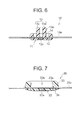
- Fig. 6 shows a modification of the tape 10 with male snap fasteners of the above-described embodiment.
- the engaging protruding portion 13 of the male fastener 11 is not simply cylindrical but divided into two parts to engaging protruding pieces 13c, 13d, which are located on opposite sides of a flat plane passing its axial line.
- the surface of the base portion 12 on an opposite side to the protrusion side of the engaging protruding portion 13 is a flat plane except the peripheral edge portion of the base portion 12 and a small concave portion 12a in the center thereof with no plural hollow portions 12b formed.
- the ring-like continuous concave groove portion 14 is formed on the surface of the base portion around a base end of the engaging protruding portion 13.
- the continuous concave groove portion 14 may be formed on the surface of the base portion 12 on the opposite side to the protrusion side of the engaging protruding portion 13.
- Fig. 7 shows a modification of the female snap fastener 21 of the above-described embodiment.
- a ring-like continuous concave groove portion 24 is formed on the surface of the base portion 22 on an opposite side to the protrusion side of the engaging protruding portion 23.
- the ring-like continuous concave groove portion 24 has its inner diameter outside the inner peripheral face of the cylindrical engaging protruding portion 23.
- the tape main body 20a is nipped at its front and rear surfaces by the molding protrusion of the cylindrical engaging protruding portion 23 and the molding protrusion of the ring-like continuous concave groove portion 24, both of which protrude in a cavity of a metal mold (not shown), such that their diameters are shifted from each other.
- the tape main body 20a is prevented effectively from being swung or deformed by resin pressure at the time of injection of molten resin, thereby providing a product having a sufficient fixing strength and stabilized configuration.
Landscapes
- Slide Fasteners, Snap Fasteners, And Hook Fasteners (AREA)
- Buckles (AREA)
Abstract
Description
Claims (6)
- A tape (10, 20) with snap fastener in which at least one male or female synthetic resin snap fastener (11, 21) is molded integrally on a tape main body (10a, 20a), said snap fastener (11, 21) comprising a base portion (12, 22) to be fixed to front and rear surfaces of the tape main body (10a, 20a) and an engaging protruding portion (13, 23) projecting vertically from the base portion (12, 22) and having a depth reaching the tape main body (10a, 20a), characterized in that
the engaging protruding portion (13, 23) is substantially cylindrical, and a ring-like continuous concave groove portion (14, 24), which has the same center as the base portion (12, 22) and an inner diameter exceeding the inner diameter of said engaging protruding portion (13, 23), is formed on any one of front and rear surfaces of the respective base portion (12, 22), and
said continuous concave groove portion (14, 24) also has a depth reaching the tape main body (10a, 20a). - A tape according to claim 1, characterized in that said continuous concave groove portion (14, 24) is circular or polygonal.
- A tape according to claim 1 or 2, characterized in that said continuous concave groove portion (14, 24) is formed around a protruding base end of said engaging protruding portion (13, 23).
- A tape according to claim 1 or 2, characterized in that said continuous concave groove portion (14, 24) is formed on a surface of the base portion on an opposite side to a protruding side of said engaging protruding portion (13, 23).
- A tape according to claim 1, characterized in that plural hollow portions (12b, 22b) having a depth reaching the tape main body (10a, 20a) and arranged intermittently in a ring form are provided on a surface at an opposite side to said base portion (12, 22) corresponding to said continuous concave groove portion (14, 24).
- A tape according to claim 1, characterized in that said tape main body (10a, 20a) consists of woven or knitted fabric and weaving patterns or stitches having gaps large enough for molten resin to pass through are formed at least at a fastener attaching portion thereof.
Applications Claiming Priority (2)
| Application Number | Priority Date | Filing Date | Title |
|---|---|---|---|
| JP2002115274A JP3971948B2 (en) | 2002-04-17 | 2002-04-17 | Tape with snap fastener |
| JP2002115274 | 2002-04-17 |
Publications (3)
| Publication Number | Publication Date |
|---|---|
| EP1354532A2 true EP1354532A2 (en) | 2003-10-22 |
| EP1354532A3 EP1354532A3 (en) | 2006-11-08 |
| EP1354532B1 EP1354532B1 (en) | 2009-06-03 |
Family
ID=28672651
Family Applications (1)
| Application Number | Title | Priority Date | Filing Date |
|---|---|---|---|
| EP03252441A Expired - Lifetime EP1354532B1 (en) | 2002-04-17 | 2003-04-16 | Tape with snap fastener |
Country Status (10)
| Country | Link |
|---|---|
| US (1) | US6757942B2 (en) |
| EP (1) | EP1354532B1 (en) |
| JP (1) | JP3971948B2 (en) |
| KR (1) | KR100479400B1 (en) |
| CN (1) | CN1224359C (en) |
| BR (1) | BR0300803A (en) |
| CA (1) | CA2421484C (en) |
| DE (1) | DE60327821D1 (en) |
| ES (1) | ES2326526T3 (en) |
| TW (1) | TWI236353B (en) |
Families Citing this family (62)
| Publication number | Priority date | Publication date | Assignee | Title |
|---|---|---|---|---|
| US20060169864A1 (en) * | 2005-02-02 | 2006-08-03 | Salerno Thomas M | Safety strap |
| US20060230583A1 (en) * | 2005-04-15 | 2006-10-19 | Button International Co., Ltd. | Snap button with pull-apart resisting structure |
| US20070258756A1 (en) * | 2006-05-05 | 2007-11-08 | Olshausen Michael C | Means for connecting plastic parts |
| US7541529B1 (en) * | 2007-08-01 | 2009-06-02 | Blair Billy W | Guitar mounting device |
| US20090205550A1 (en) * | 2008-02-20 | 2009-08-20 | George Melissa S | Temporary hemming device |
| CN102325475B (en) * | 2009-02-23 | 2014-06-11 | Ykk株式会社 | button |
| US9812684B2 (en) | 2010-11-09 | 2017-11-07 | GM Global Technology Operations LLC | Using elastic averaging for alignment of battery stack, fuel cell stack, or other vehicle assembly |
| US20120122617A1 (en) * | 2010-11-16 | 2012-05-17 | Szurley Andrew J | Multi-component lacrosse head |
| US9618026B2 (en) | 2012-08-06 | 2017-04-11 | GM Global Technology Operations LLC | Semi-circular alignment features of an elastic averaging alignment system |
| US20140041185A1 (en) * | 2012-08-13 | 2014-02-13 | GM Global Technology Operations LLC | Elastic tube alignment and attachment system and method for precisely locating and attaching components |
| US9463538B2 (en) | 2012-08-13 | 2016-10-11 | GM Global Technology Operations LLC | Alignment system and method thereof |
| JP2014147668A (en) * | 2013-01-31 | 2014-08-21 | Ykk Corp | Snap fastener |
| US9556890B2 (en) | 2013-01-31 | 2017-01-31 | GM Global Technology Operations LLC | Elastic alignment assembly for aligning mated components and method of reducing positional variation |
| US9278642B2 (en) | 2013-04-04 | 2016-03-08 | GM Global Technology Operations LLC | Elastically deformable flange locator arrangement and method of reducing positional variation |
| US9388838B2 (en) | 2013-04-04 | 2016-07-12 | GM Global Technology Operations LLC | Elastic retaining assembly for matable components and method of assembling |
| US9447840B2 (en) | 2013-06-11 | 2016-09-20 | GM Global Technology Operations LLC | Elastically deformable energy management assembly and method of managing energy absorption |
| US9488205B2 (en) | 2013-07-12 | 2016-11-08 | GM Global Technology Operations LLC | Alignment arrangement for mated components and method |
| US9303667B2 (en) | 2013-07-18 | 2016-04-05 | Gm Global Technology Operations, Llc | Lobular elastic tube alignment system for providing precise four-way alignment of components |
| US9863454B2 (en) | 2013-08-07 | 2018-01-09 | GM Global Technology Operations LLC | Alignment system for providing precise alignment and retention of components of a sealable compartment |
| US9458876B2 (en) | 2013-08-28 | 2016-10-04 | GM Global Technology Operations LLC | Elastically deformable alignment fastener and system |
| US9463831B2 (en) | 2013-09-09 | 2016-10-11 | GM Global Technology Operations LLC | Elastic tube alignment and fastening system for providing precise alignment and fastening of components |
| US9457845B2 (en) | 2013-10-02 | 2016-10-04 | GM Global Technology Operations LLC | Lobular elastic tube alignment and retention system for providing precise alignment of components |
| US9511802B2 (en) | 2013-10-03 | 2016-12-06 | GM Global Technology Operations LLC | Elastically averaged alignment systems and methods |
| US9669774B2 (en) | 2013-10-11 | 2017-06-06 | GM Global Technology Operations LLC | Reconfigurable vehicle interior assembly |
| US9481317B2 (en) | 2013-11-15 | 2016-11-01 | GM Global Technology Operations LLC | Elastically deformable clip and method |
| US9447806B2 (en) | 2013-12-12 | 2016-09-20 | GM Global Technology Operations LLC | Self-retaining alignment system for providing precise alignment and retention of components |
| US9428123B2 (en) | 2013-12-12 | 2016-08-30 | GM Global Technology Operations LLC | Alignment and retention system for a flexible assembly |
| US9599279B2 (en) | 2013-12-19 | 2017-03-21 | GM Global Technology Operations LLC | Elastically deformable module installation assembly |
| US9446722B2 (en) | 2013-12-19 | 2016-09-20 | GM Global Technology Operations LLC | Elastic averaging alignment member |
| US9541113B2 (en) | 2014-01-09 | 2017-01-10 | GM Global Technology Operations LLC | Elastically averaged alignment systems and methods |
| US9428046B2 (en) | 2014-04-02 | 2016-08-30 | GM Global Technology Operations LLC | Alignment and retention system for laterally slideably engageable mating components |
| US9657807B2 (en) | 2014-04-23 | 2017-05-23 | GM Global Technology Operations LLC | System for elastically averaging assembly of components |
| US9429176B2 (en) | 2014-06-30 | 2016-08-30 | GM Global Technology Operations LLC | Elastically averaged alignment systems and methods |
| US9758110B2 (en) | 2015-01-12 | 2017-09-12 | GM Global Technology Operations LLC | Coupling system |
| US10107319B2 (en) | 2015-03-02 | 2018-10-23 | GM Global Technology Operations LLC | Elastically averaged alignment systems and methods |
| WO2017168666A1 (en) * | 2016-03-30 | 2017-10-05 | Ykk株式会社 | Snap button and male body forming method |
| US12108853B2 (en) | 2019-01-06 | 2024-10-08 | Yeti Coolers, Llc | Luggage system |
| CN116729803B (en) | 2017-06-12 | 2026-06-09 | 野醍冷却器有限责任公司 | Container and latch assembly |
| US11685573B2 (en) | 2017-06-12 | 2023-06-27 | Yeti Coolers, Llc | Carry strap for container |
| US11976498B2 (en) | 2017-06-12 | 2024-05-07 | Yeti Coolers, Llc | Container and latching system |
| AU201717615S (en) | 2017-06-12 | 2018-01-15 | Yeti Coolers | Container |
| US11172647B2 (en) * | 2018-10-01 | 2021-11-16 | PetSmart Home Office, Inc. | System and method for coupling an exercise wheel accessory to a small animal habitat |
| USD907445S1 (en) | 2018-12-11 | 2021-01-12 | Yeti Coolers, Llc | Container accessories |
| USD904829S1 (en) | 2018-12-11 | 2020-12-15 | Yeti Coolers, Llc | Container accessories |
| US12225993B2 (en) | 2019-01-06 | 2025-02-18 | Yeti Coolers, Llc | Luggage system |
| JP7303313B2 (en) | 2019-01-06 | 2023-07-04 | イエティ クーラーズ エルエルシー | luggage system |
| WO2021102550A1 (en) * | 2019-11-29 | 2021-06-03 | Incour Innovations Ltd. | Snap fastener and snap strap fastener for clothing |
| USD963344S1 (en) | 2020-06-30 | 2022-09-13 | Yeti Coolers, Llc | Luggage |
| USD951643S1 (en) | 2020-06-30 | 2022-05-17 | Yeti Coolers, Llc | Luggage |
| USD954436S1 (en) | 2020-06-30 | 2022-06-14 | Yeti Coolers, Llc | Luggage |
| USD961926S1 (en) | 2020-06-30 | 2022-08-30 | Yeti Coolers, Llc | Luggage |
| USD994438S1 (en) | 2020-12-16 | 2023-08-08 | Yeti Coolers, Llc | Container |
| USD960648S1 (en) | 2020-12-16 | 2022-08-16 | Yeti Coolers, Llc | Container accessory |
| USD985937S1 (en) | 2020-12-16 | 2023-05-16 | Yeti Coolers, Llc | Container |
| CN114947314A (en) * | 2022-05-09 | 2022-08-30 | 孙全伟 | Novel fastener |
| KR102541754B1 (en) | 2022-11-08 | 2023-06-13 | (주) 대전통일 | Sleeve member-type fireproof filler connection device of |
| KR102541758B1 (en) | 2022-12-21 | 2023-06-13 | (주) 대전통일 | Installation of fire-resistant fillers for sleeves and drainage system to prevent falling |
| KR102541775B1 (en) | 2022-12-21 | 2023-06-13 | (주) 대전통일 | Installation of fire-resistant fillers for sleeves and piping connections to prevent falling |
| KR102571553B1 (en) | 2023-02-24 | 2023-08-29 | (주) 대전통일 | Undercut connection to prevent falling of refractory filler |
| KR102553228B1 (en) | 2023-02-24 | 2023-07-10 | (주) 대전통일 | Pipe connection to prevent falling of refractory filler for sleeve |
| KR102683762B1 (en) | 2024-03-19 | 2024-07-10 | (주) 대전통일 | Fire resistant filling installation type drain pip |
| KR102772254B1 (en) | 2024-07-16 | 2025-02-26 | (주) 대전통일 | Floor Drain Fire Filling Stand |
Family Cites Families (10)
| Publication number | Priority date | Publication date | Assignee | Title |
|---|---|---|---|---|
| US2895199A (en) * | 1955-04-12 | 1959-07-21 | United Carr Fastener Corp | All plastic separable fastener of the press button type |
| US3243858A (en) * | 1964-05-08 | 1966-04-05 | United Carr Inc | Fastener components adapted for electronic heat sealing |
| JP3678925B2 (en) * | 1998-11-26 | 2005-08-03 | Ykk株式会社 | Fasteners with tape |
| US3613181A (en) * | 1970-08-26 | 1971-10-19 | Scovill Manufacturing Co | Snap fastener socket |
| DE2163686C2 (en) * | 1971-12-22 | 1974-04-11 | Fa. A. Raymond, 7850 Loerrach | Plastic snap fastener |
| JPS62155805A (en) * | 1985-12-27 | 1987-07-10 | モリト株式会社 | Snap fastener and its production |
| JPH1033211A (en) * | 1996-07-29 | 1998-02-10 | Morito Kk | Snap with tape |
| JP3106199B2 (en) * | 1996-07-29 | 2000-11-06 | モリト株式会社 | Snap with tape |
| JP4074404B2 (en) * | 1999-02-16 | 2008-04-09 | 武田精機株式会社 | Tape-like snap fastener for clothes |
| JP2001008711A (en) * | 1999-04-28 | 2001-01-16 | Morito Co Ltd | Snap fastener with peeling direction |
-
2002
- 2002-04-17 JP JP2002115274A patent/JP3971948B2/en not_active Expired - Lifetime
-
2003
- 2003-03-11 CA CA002421484A patent/CA2421484C/en not_active Expired - Fee Related
- 2003-03-17 BR BR0300803-7A patent/BR0300803A/en not_active IP Right Cessation
- 2003-03-20 TW TW092106214A patent/TWI236353B/en not_active IP Right Cessation
- 2003-04-15 CN CNB031107524A patent/CN1224359C/en not_active Expired - Lifetime
- 2003-04-16 KR KR10-2003-0023870A patent/KR100479400B1/en not_active Expired - Fee Related
- 2003-04-16 EP EP03252441A patent/EP1354532B1/en not_active Expired - Lifetime
- 2003-04-16 ES ES03252441T patent/ES2326526T3/en not_active Expired - Lifetime
- 2003-04-16 DE DE60327821T patent/DE60327821D1/en not_active Expired - Lifetime
- 2003-04-16 US US10/414,244 patent/US6757942B2/en not_active Expired - Lifetime
Also Published As
| Publication number | Publication date |
|---|---|
| TW200305377A (en) | 2003-11-01 |
| DE60327821D1 (en) | 2009-07-16 |
| TWI236353B (en) | 2005-07-21 |
| HK1056301A1 (en) | 2004-02-13 |
| CA2421484C (en) | 2006-09-19 |
| CN1451334A (en) | 2003-10-29 |
| CA2421484A1 (en) | 2003-10-17 |
| JP2003304911A (en) | 2003-10-28 |
| KR20030082446A (en) | 2003-10-22 |
| US6757942B2 (en) | 2004-07-06 |
| BR0300803A (en) | 2004-06-08 |
| KR100479400B1 (en) | 2005-03-28 |
| EP1354532A3 (en) | 2006-11-08 |
| US20030196300A1 (en) | 2003-10-23 |
| CN1224359C (en) | 2005-10-26 |
| EP1354532B1 (en) | 2009-06-03 |
| JP3971948B2 (en) | 2007-09-05 |
| ES2326526T3 (en) | 2009-10-14 |
Similar Documents
| Publication | Publication Date | Title |
|---|---|---|
| US6757942B2 (en) | Tape with snap fastener | |
| US9420853B2 (en) | Slide fastener with flat elements | |
| FI94481B (en) | Traction part of the zipper slider | |
| EP0373624B1 (en) | Method of making ornaments | |
| EP1084642B1 (en) | A tape-mounted fastener and method of manufacture thereof | |
| EP1537801B1 (en) | Method of making a slide fastener | |
| US6976291B2 (en) | Tape-mounted fastener and methods for manufacturing and using the same | |
| EP1702529B1 (en) | Linear slide fastener | |
| EP1314367A2 (en) | A fastener for a brassier or brassier-like garment, a manufacturing method therof and a brassier or brassier-like garment using such a fastener | |
| EP1523900B1 (en) | Top end stop of linear slide fastener | |
| US20050011232A1 (en) | Knitted surface fastener | |
| EP2638818B1 (en) | Fastener stringer, slide fastener, and method for manufacturing fastener stringer | |
| JP3055106U (en) | Female snap with tape | |
| HK1056301B (en) | Tape with snap fastener | |
| EP1444913A1 (en) | Button fastener | |
| TW201815310A (en) | Zipper with continuous snapping elements capable of lowering the protruding ridge height inside the reverse slider and enhancing the completeness of protruding ridge when being cast molded | |
| CA2116153C (en) | Hanging cloth attaching device | |
| KR200179010Y1 (en) | Belt | |
| KR101448194B1 (en) | Button for the mold for fabricating the same | |
| JPH0437449Y2 (en) | ||
| TW202007300A (en) | A continued elements slide fastener | |
| JP2895379B2 (en) | Cloth suspension connector | |
| US3413986A (en) | Ornamental hair fastener | |
| JP3016616U (en) | Color closure | |
| JP2001190310A (en) | Manufacturing method of tape-shaped snap |
Legal Events
| Date | Code | Title | Description |
|---|---|---|---|
| PUAI | Public reference made under article 153(3) epc to a published international application that has entered the european phase |
Free format text: ORIGINAL CODE: 0009012 |
|
| 17P | Request for examination filed |
Effective date: 20030429 |
|
| AK | Designated contracting states |
Kind code of ref document: A2 Designated state(s): AT BE BG CH CY CZ DE DK EE ES FI FR GB GR HU IE IT LI LU MC NL PT RO SE SI SK TR |
|
| AX | Request for extension of the european patent |
Extension state: AL LT LV MK |
|
| PUAL | Search report despatched |
Free format text: ORIGINAL CODE: 0009013 |
|
| AK | Designated contracting states |
Kind code of ref document: A3 Designated state(s): AT BE BG CH CY CZ DE DK EE ES FI FR GB GR HU IE IT LI LU MC NL PT RO SE SI SK TR |
|
| AX | Request for extension of the european patent |
Extension state: AL LT LV MK |
|
| 17Q | First examination report despatched |
Effective date: 20070611 |
|
| AKX | Designation fees paid |
Designated state(s): DE ES FR GB IT TR |
|
| GRAP | Despatch of communication of intention to grant a patent |
Free format text: ORIGINAL CODE: EPIDOSNIGR1 |
|
| GRAS | Grant fee paid |
Free format text: ORIGINAL CODE: EPIDOSNIGR3 |
|
| RIN1 | Information on inventor provided before grant (corrected) |
Inventor name: MATSUSHIMA,HIDEYUKI Inventor name: MATSUI, SHOJI |
|
| GRAA | (expected) grant |
Free format text: ORIGINAL CODE: 0009210 |
|
| AK | Designated contracting states |
Kind code of ref document: B1 Designated state(s): DE ES FR GB IT TR |
|
| REG | Reference to a national code |
Ref country code: GB Ref legal event code: FG4D |
|
| REF | Corresponds to: |
Ref document number: 60327821 Country of ref document: DE Date of ref document: 20090716 Kind code of ref document: P |
|
| REG | Reference to a national code |
Ref country code: ES Ref legal event code: FG2A Ref document number: 2326526 Country of ref document: ES Kind code of ref document: T3 |
|
| PLBE | No opposition filed within time limit |
Free format text: ORIGINAL CODE: 0009261 |
|
| STAA | Information on the status of an ep patent application or granted ep patent |
Free format text: STATUS: NO OPPOSITION FILED WITHIN TIME LIMIT |
|
| 26N | No opposition filed |
Effective date: 20100304 |
|
| PGFP | Annual fee paid to national office [announced via postgrant information from national office to epo] |
Ref country code: ES Payment date: 20100505 Year of fee payment: 8 Ref country code: FR Payment date: 20100521 Year of fee payment: 8 |
|
| PGFP | Annual fee paid to national office [announced via postgrant information from national office to epo] |
Ref country code: IT Payment date: 20100423 Year of fee payment: 8 |
|
| PGFP | Annual fee paid to national office [announced via postgrant information from national office to epo] |
Ref country code: GB Payment date: 20100401 Year of fee payment: 8 |
|
| GBPC | Gb: european patent ceased through non-payment of renewal fee |
Effective date: 20110416 |
|
| REG | Reference to a national code |
Ref country code: FR Ref legal event code: ST Effective date: 20111230 |
|
| PG25 | Lapsed in a contracting state [announced via postgrant information from national office to epo] |
Ref country code: FR Free format text: LAPSE BECAUSE OF NON-PAYMENT OF DUE FEES Effective date: 20110502 |
|
| PG25 | Lapsed in a contracting state [announced via postgrant information from national office to epo] |
Ref country code: GB Free format text: LAPSE BECAUSE OF NON-PAYMENT OF DUE FEES Effective date: 20110416 Ref country code: IT Free format text: LAPSE BECAUSE OF NON-PAYMENT OF DUE FEES Effective date: 20110416 |
|
| REG | Reference to a national code |
Ref country code: ES Ref legal event code: FD2A Effective date: 20130606 |
|
| PG25 | Lapsed in a contracting state [announced via postgrant information from national office to epo] |
Ref country code: ES Free format text: LAPSE BECAUSE OF NON-PAYMENT OF DUE FEES Effective date: 20110417 |
|
| PGFP | Annual fee paid to national office [announced via postgrant information from national office to epo] |
Ref country code: DE Payment date: 20220302 Year of fee payment: 20 |
|
| PGFP | Annual fee paid to national office [announced via postgrant information from national office to epo] |
Ref country code: TR Payment date: 20220413 Year of fee payment: 20 |
|
| REG | Reference to a national code |
Ref country code: DE Ref legal event code: R071 Ref document number: 60327821 Country of ref document: DE |