EP1354184B2 - A method of wear testing a tire - Google Patents
A method of wear testing a tire Download PDFInfo
- Publication number
- EP1354184B2 EP1354184B2 EP02704165.6A EP02704165A EP1354184B2 EP 1354184 B2 EP1354184 B2 EP 1354184B2 EP 02704165 A EP02704165 A EP 02704165A EP 1354184 B2 EP1354184 B2 EP 1354184B2
- Authority
- EP
- European Patent Office
- Prior art keywords
- vehicle
- tire
- wear test
- wear
- accelerations
- Prior art date
- Legal status (The legal status is an assumption and is not a legal conclusion. Google has not performed a legal analysis and makes no representation as to the accuracy of the status listed.)
- Expired - Lifetime
Links
- 238000012360 testing method Methods 0.000 title claims description 89
- 238000000034 method Methods 0.000 title claims description 29
- 230000001133 acceleration Effects 0.000 claims description 28
- 238000012512 characterization method Methods 0.000 claims description 14
- 238000005259 measurement Methods 0.000 description 11
- 230000008901 benefit Effects 0.000 description 4
- 230000008569 process Effects 0.000 description 3
- 238000004891 communication Methods 0.000 description 2
- 230000009977 dual effect Effects 0.000 description 2
- 230000000694 effects Effects 0.000 description 2
- 230000005484 gravity Effects 0.000 description 2
- 238000003860 storage Methods 0.000 description 2
- 230000005540 biological transmission Effects 0.000 description 1
- 230000008859 change Effects 0.000 description 1
- 238000013500 data storage Methods 0.000 description 1
- 238000011161 development Methods 0.000 description 1
- 238000012432 intermediate storage Methods 0.000 description 1
- 238000010338 mechanical breakdown Methods 0.000 description 1
- 230000007246 mechanism Effects 0.000 description 1
- 238000012986 modification Methods 0.000 description 1
- 230000004048 modification Effects 0.000 description 1
- 238000010998 test method Methods 0.000 description 1
- 238000012546 transfer Methods 0.000 description 1
Images
Classifications
-
- G—PHYSICS
- G01—MEASURING; TESTING
- G01M—TESTING STATIC OR DYNAMIC BALANCE OF MACHINES OR STRUCTURES; TESTING OF STRUCTURES OR APPARATUS, NOT OTHERWISE PROVIDED FOR
- G01M17/00—Testing of vehicles
- G01M17/007—Wheeled or endless-tracked vehicles
- G01M17/02—Tyres
-
- G—PHYSICS
- G01—MEASURING; TESTING
- G01N—INVESTIGATING OR ANALYSING MATERIALS BY DETERMINING THEIR CHEMICAL OR PHYSICAL PROPERTIES
- G01N3/00—Investigating strength properties of solid materials by application of mechanical stress
- G01N3/56—Investigating resistance to wear or abrasion
-
- G—PHYSICS
- G01—MEASURING; TESTING
- G01N—INVESTIGATING OR ANALYSING MATERIALS BY DETERMINING THEIR CHEMICAL OR PHYSICAL PROPERTIES
- G01N33/00—Investigating or analysing materials by specific methods not covered by groups G01N1/00 - G01N31/00
- G01N33/0078—Testing material properties on manufactured objects
- G01N33/0083—Vehicle parts
- G01N33/0085—Wheels
Definitions
- the present invention relates to a method of wear testing a tire using an indoor tire wear test machine. Such a method is for example described in U.S. patent 3,563,088 .
- a wear test drum provides a rotating surface that engages the tire to simulate a road surface.
- the wear test drum provides mechanisms for varying the force between the tire and the rotating surface.
- the velocity of the rotating surface may also be varied.
- the user may simulate actual public road driving conditions by varying these forces and the velocity.
- the problem in the prior art is that the user cannot easily determine what forces and velocities to use to simulate public road driving conditions for a specific vehicle.
- the total length of the daily commute over a one year period may be 15,000 miles.
- the forces between the tire and the road constantly change through this commute and the person conducting the indoor wear test desires to accurately simulate these forces on the test tire with the indoor test drum.
- One method of predicting the tire forces is to instrument a test car with wheel force transducers that are mounted as part of the wheel and rotate with the wheel/tire assembly while the vehicle is driven over a controlled test track.
- the vehicle is equipped with a data acquisition system that stores signals from the transducers. For instance, front and rear radial force, lateral force, drive/brake force, and tire velocities may be recorded. The angular position of each transducer must also be recorded because the transducers rotate with the tires.
- a problem with this measurement system is that the equipment is difficult to transport from test location to test location, the setup time is long, and the vehicle cannot be driven on public roads while equipped with the transducers. The data is thus only gathered on a test track that simulates public road driving conditions.
- the process of gathering the force histories for a given car with a given tire is expensive and often consumes weeks of time. The process must be repeated for different cars and for different tires.
- the art thus desires a faster and easier method of generating tire loading histories for indoor wear tests.
- the art also desires that the method for generating the tire loading histories result in more accurate load histories for the test machine.
- the present invention provides a method of wear testing a tire using an indoor tire wear test machine as defined in claim 1.
- Sample tire forces are measured with a test system.
- the data from the test system is used to create formulas that relate the tire forces to the accelerations experienced by the vehicle.
- An instrumented vehicle driven over a wear test course records data about the vehicle while it is driven over the course. This data is used with the formulas to create the input forces for an indoor wear test machine.
- the disclosure also provides a method of translating the data gathered from the outdoor test vehicle into tire load data that may be used to operate an indoor tire wear test drum to perform an indoor tire wear test.
- the method of the present invention is generally performed by first characterizing the vehicle for which the tire is being wear tested.
- the method also requires a wear test course to be measured with a vehicle.
- the invention combines the course measurements with the vehicle characterization to create a load history that is used to drive an indoor mechanical wear test machine to wear test the tire.
- the resulting wear test accurately reflects the wear on the tire if the tire had been used on the vehicle over the test course.
- the invention allows the wear test to occur indoors without the hassle of mechanical breakdowns over a much shorter time than in the past.
- the test courses may be used with any vehicle characterizations to allow different vehicles to be tested on a single course.
- different courses may be used with a single vehicle characterization to compare how a tire will perform with a vehicle on different courses. The uncontrolled effect of weather variability is also avoided.
- the vehicle characterization step of this method measures the forces experienced by the tires of a vehicle under a variety of driving conditions.
- the vehicle characterization step is performed on the vehicle on which the tires are to be wear tested for. For instance, if the tire to be wear tested is going to be used on a specific passenger car, the specific passenger car - or a similar car - should be used during the vehicle characterization step.
- the vehicle characterization step may be repeated for each type of vehicle for which a tire is to be wear tested.
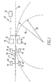
- the vehicle characterization data may be gathered using a dual force platform measurement system 10 ( Fig. 1 ).
- a dual force platform measurement system 10 ( Fig. 1 ).
- AMTI Model OR6-5-2000 One system known in the art is referred to as AMTI Model OR6-5-2000.
- This system includes in-ground force platforms 12 configured to be driven over by the vehicle 14.
- the platform spacing is adjustable to accommodate different vehicle track widths.
- three directional forces fore-aft (Fx), lateral (Fy), and vertical (Fz)
- the data may be immediately stored by computer 20 or stored in an intermediate storage device and then stored in computer 20.
- Transducers 18 may be in communication with storage device 20 by wires or wireless transmissions.
- a measurement device may be used to measure the speed of vehicle 14.
- the vehicle speed may be processed from the data gathered as tires 16 pass over platforms 12.
- transducers 22 are positioned at the vehicle center of gravity to measure accelerations (fore-aft and lateral) during passage of tires 16 across force platforms 12.
- Appropriate wheel inclination measurement devices 24 are also used to measure the wheel inclination angles while tires 16 are passing over force platforms 12.
- One type of wheel inclination angle measurement device is disclosed in United States Patent 5,561,244 . Data from the two load platforms, the in-vehicle measurement of accelerations, and from the wheel inclination device are collected simultaneously.
- the directional forces, velocity, accelerations, and wheel inclination angles are measured while vehicle 14 passes over platforms 12 at a range of speeds (for example, 2 to 20 miles per hour), turn radii 26 (for example, 30 feet to 200 feet), and straight driving acceleration/deceleration conditions 28 (for example, +0.5 g to -0.5 g).
- speeds for example, 2 to 20 miles per hour
- turn radii 26 for example, 30 feet to 200 feet
- straight driving acceleration/deceleration conditions 28 for example, +0.5 g to -0.5 g.
- a wear test course may be any test course of interest in which a tire manufacturer or automobile manufacturer is interested in gathering tire wear test information.
- the wear test course may be a typical commute for a target driver.
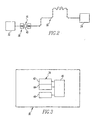
- a commuting wear course 30 includes a starting position at the driver's residence 32 and a final position at the driver's place of employment 34.
- the test course also may be a city driving course that would be typically used by a taxi cab driver.
- the type of wear test courses available to the method of the present invention are essentially limitless.
- Test course 30 is characterized by installing a measuring device 36 in a vehicle 38 that measures fore-aft and lateral acceleration of the vehicle center of gravity while it is driven over course 30.
- a measuring device 36 measures fore-aft and lateral acceleration of the vehicle center of gravity while it is driven over course 30.
- Another measurement device 40 records the velocity of the vehicle.
- Device 40 may be one that does not contact the road surface in order to determine velocity.
- device 40 measures the steering angle of vehicle 38 rather than the vehicle velocity.
- two accelerometers 42 and 44 are used to measure the fore-aft acceleration and the lateral acceleration.
- An appropriate data storage device 46 such as a personal computer may be in communication with measurement devices 40, 42, and 44 to record test data at regular intervals while vehicle 38 is driven over test course 30.
- the data is recorded every three feet of travel over the entire wear test course 30.
- One advantage of this step over prior methods is that the instrumentation required to gather this data may be placed inside the vehicle allowing the vehicle to remain "street legal" and driven over public roads. In the past, the instrumentation was on the outside of the vehicle. The present invention also prevents inclement weather from ruining the data gathering steps.
- Another advantage is that devices 40, 42, and 44 are compact and may be easily shipped. The measurements devices may also be quickly installed in the test vehicle.
- the data gathered over the wear test course 30 is stored and creates a mathematical test course that can be applied to different vehicles. Each cornering maneuver, each braking and acceleration event, every hill and town captured and reproduced, in real-time, in this mathematical test course.
- the user may drive multiple test courses in orderto create a library of test courses that may be applied to vehicles as desired.
- the user After the user has characterized a vehicle, the user develops equations that relate the fore-aft (Fx), lateral (Fy), and vertical forces (Fz) to the fore-aft acceleration (Ax), lateral acceleration (Ay), and velocity (Vx) (or steering angle), measured on the wear test course.
- the user also develops an equation that relates the inclination angle (I.A.), of the tires to the forward acceleration, lateral acceleration, and velocity (or steering angle) measured on the wear test course.
- Each of these equations includes coefficients that relate the accelerations and velocities to the forces.
- the values of the coefficients are determined by regression to give a best fit of the equation to the measured data.
- the equations and the coefficients constitute a vehicle model for predicting the forces and inclination angle when given the two accelerations and velocity.
- a separate set of equation coefficients is developed to characterize each wheel position on the vehicle.
- the following table illustrates the terms used in each equation.
- the coefficients a 0 through a 6 are computed by least squares regression with the measured forces, inclination angles and accelerations from the vehicle characterization step.
- a shaded box indicates no use of that term in the equation for that independent variable.
- Checks, ⁇ indicate that the term is included in the equation.
- F z a 0 + a 1 *A y + a 2 *A y 2 + a 3 *K + a 4 *K 2 +a 5 *Ax.
- the steering angle can be used in place of K if preferred.
- the acceleration terms are generally needed to capture load transfer due to inertial loads.
- the curvature terms are needed to account for forces produced by the geometric effects of the steering system.
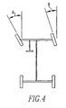
- Fig. 4 shows why a vehicle steering system and vehicle geometry alters the angles of the tires with respect to the road surface. Angle A is different from angle B and thus the front tires experience different forces based on the radius of the curve.
- one additional term is added to the Fx equation to help account for aerodynamic drag for tires on drive positions.
- the coefficient of this term is determined from the product of the aerodynamic drag coefficient and frontal area of the vehicle (determined from other sources). The contribution from this term is typically insignificant at the relatively low vehicle velocities used during the vehicle characterization process.
- the user may program an indoor mechanical wear test machine (such as the MTS Model 860 RoadWheel Tread Wear Test System) to simulate the outdoor wear test course.
- the user selects a characterized wear test course and calculates the forces as they relate to time for the vehicle. These forces are input into the indoor mechanical wear test machine and a number of miles is selected for the test.
- the indoor mechanical wear test machine rotates the tire against the drum and creates the forces input by the user.
- the wear test machine continuously repeats the wear test course as if the tire was being driven over the wear test course for the selected number of miles. For instance, the user may test the tire over a commuting course for 15,000 miles.
- the method of the present invention allows tires to be efficiently and accurately wear tested using indoor testing equipment.
- the method allows the indoor testing equipment to effectively simulate each tire position of a particular vehicle traveling on a specific outdoor road wear course.
- the method allows the characterized vehicles to be tested on any characterized wear test course and allows a single wear test course to be used with any characterized vehicle.
Landscapes
- Physics & Mathematics (AREA)
- General Physics & Mathematics (AREA)
- Health & Medical Sciences (AREA)
- Life Sciences & Earth Sciences (AREA)
- Chemical & Material Sciences (AREA)
- General Health & Medical Sciences (AREA)
- Biochemistry (AREA)
- Analytical Chemistry (AREA)
- Immunology (AREA)
- Pathology (AREA)
- Engineering & Computer Science (AREA)
- Food Science & Technology (AREA)
- Medicinal Chemistry (AREA)
- Tires In General (AREA)
- Length Measuring Devices With Unspecified Measuring Means (AREA)
Description
- The present invention relates to a method of wear testing a tire using an indoor tire wear test machine. Such a method is for example described in
U.S. patent 3,563,088 . - Automobile and tire manufacturers desire wear testing to be performed on tires. Different methods of wear testing tires are known in the art. In one known method, the test tires are placed on a vehicle that will be frequently driven. The tires are measured after the vehicle is driven a selected number of miles. Another known test procedure is performed indoor on a wear test drum. A wear test drum provides a rotating surface that engages the tire to simulate a road surface. The wear test drum provides mechanisms for varying the force between the tire and the rotating surface. The velocity of the rotating surface may also be varied. The user may simulate actual public road driving conditions by varying these forces and the velocity. The problem in the prior art is that the user cannot easily determine what forces and velocities to use to simulate public road driving conditions for a specific vehicle.
- For instance, one may wish to simulate tire wear with a specific tire on a specific vehicle over a daily commute that includes country road, highway, and city road driving conditions. The total length of the daily commute over a one year period may be 15,000 miles. The forces between the tire and the road constantly change through this commute and the person conducting the indoor wear test desires to accurately simulate these forces on the test tire with the indoor test drum.
- One method of predicting the tire forces is to instrument a test car with wheel force transducers that are mounted as part of the wheel and rotate with the wheel/tire assembly while the vehicle is driven over a controlled test track. The vehicle is equipped with a data acquisition system that stores signals from the transducers. For instance, front and rear radial force, lateral force, drive/brake force, and tire velocities may be recorded. The angular position of each transducer must also be recorded because the transducers rotate with the tires. A problem with this measurement system is that the equipment is difficult to transport from test location to test location, the setup time is long, and the vehicle cannot be driven on public roads while equipped with the transducers. The data is thus only gathered on a test track that simulates public road driving conditions. The process of gathering the force histories for a given car with a given tire is expensive and often consumes weeks of time. The process must be repeated for different cars and for different tires. The art thus desires a faster and easier method of generating tire loading histories for indoor wear tests. The art also desires that the method for generating the tire loading histories result in more accurate load histories for the test machine.
- The present invention provides a method of wear testing a tire using an indoor tire wear test machine as defined in claim 1. Sample tire forces are measured with a test system. The data from the test system is used to create formulas that relate the tire forces to the accelerations experienced by the vehicle. An instrumented vehicle driven over a wear test course records data about the vehicle while it is driven over the course. This data is used with the formulas to create the input forces for an indoor wear test machine.
- The disclosure also provides a method of translating the data gathered from the outdoor test vehicle into tire load data that may be used to operate an indoor tire wear test drum to perform an indoor tire wear test.
-
-
Fig. 1 is a schematic view of a dual force platform test facility. -
Fig. 2 is a schematic view of a wear test course being driven by a test vehicle. -
Fig. 3 is a schematic view of the instrumented vehicle depicted inFig. 2 . -
Fig. 4 is a schematic view of a vehicle showing the different steering angles of the front tires. - The method of the present invention is generally performed by first characterizing the vehicle for which the tire is being wear tested. The method also requires a wear test course to be measured with a vehicle. The invention combines the course measurements with the vehicle characterization to create a load history that is used to drive an indoor mechanical wear test machine to wear test the tire. The resulting wear test accurately reflects the wear on the tire if the tire had been used on the vehicle over the test course. The invention allows the wear test to occur indoors without the hassle of mechanical breakdowns over a much shorter time than in the past. In addition to the convenience and time advantages, the test courses may be used with any vehicle characterizations to allow different vehicles to be tested on a single course. In addition, different courses may be used with a single vehicle characterization to compare how a tire will perform with a vehicle on different courses. The uncontrolled effect of weather variability is also avoided.
- The vehicle characterization step of this method measures the forces experienced by the tires of a vehicle under a variety of driving conditions. The vehicle characterization step is performed on the vehicle on which the tires are to be wear tested for. For instance, if the tire to be wear tested is going to be used on a specific passenger car, the specific passenger car - or a similar car - should be used during the vehicle characterization step.
- The vehicle characterization step may be repeated for each type of vehicle for which a tire is to be wear tested. The vehicle characterization data may be gathered using a dual force platform measurement system 10 (
Fig. 1 ). One system known in the art is referred to as AMTI Model OR6-5-2000. This system includes in-ground force platforms 12 configured to be driven over by the vehicle 14. The platform spacing is adjustable to accommodate different vehicle track widths. When thetires 16 of the vehicle 14 engage theforce platforms 12, three directional forces (fore-aft (Fx), lateral (Fy), and vertical (Fz)) are measured bytransducers 18 and recorded by anappropriate storage device 20 such as a computer. The data may be immediately stored bycomputer 20 or stored in an intermediate storage device and then stored incomputer 20.Transducers 18 may be in communication withstorage device 20 by wires or wireless transmissions. A measurement device may be used to measure the speed of vehicle 14. In another embodiment of the invention, the vehicle speed may be processed from the data gathered astires 16 pass overplatforms 12. - In addition to the directional force measurements,
transducers 22 are positioned at the vehicle center of gravity to measure accelerations (fore-aft and lateral) during passage oftires 16 acrossforce platforms 12. Appropriate wheelinclination measurement devices 24 are also used to measure the wheel inclination angles whiletires 16 are passing overforce platforms 12. One type of wheel inclination angle measurement device is disclosed in United States Patent5,561,244 . Data from the two load platforms, the in-vehicle measurement of accelerations, and from the wheel inclination device are collected simultaneously. - The directional forces, velocity, accelerations, and wheel inclination angles are measured while vehicle 14 passes over
platforms 12 at a range of speeds (for example, 2 to 20 miles per hour), turn radii 26 (for example, 30 feet to 200 feet), and straight driving acceleration/deceleration conditions 28 (for example, +0.5 g to -0.5 g). These test conditions span typically encountered levels of steering, cornering acceleration, braking acceleration, forward acceleration, and straight uniform motion produced in most day to day driving conditions on public roads and highways. - Another step of the method of the present invention is to characterize a wear test course. A wear test course may be any test course of interest in which a tire manufacturer or automobile manufacturer is interested in gathering tire wear test information. For instance, the wear test course may be a typical commute for a target driver. In
Fig. 2 , a commutingwear course 30 includes a starting position at the driver'sresidence 32 and a final position at the driver's place ofemployment 34. The test course also may be a city driving course that would be typically used by a taxi cab driver. The type of wear test courses available to the method of the present invention are essentially limitless. -
Test course 30 is characterized by installing a measuringdevice 36 in avehicle 38 that measures fore-aft and lateral acceleration of the vehicle center of gravity while it is driven overcourse 30. An advantage is thattest vehicle 38 does not have to be identical to test vehicle 14 described above. Anothermeasurement device 40 records the velocity of the vehicle.Device 40 may be one that does not contact the road surface in order to determine velocity. Alternatively,device 40 measures the steering angle ofvehicle 38 rather than the vehicle velocity. In one embodiment of the invention, twoaccelerometers 42 and 44 are used to measure the fore-aft acceleration and the lateral acceleration. An appropriatedata storage device 46 such as a personal computer may be in communication withmeasurement devices vehicle 38 is driven overtest course 30. In one embodiment, the data is recorded every three feet of travel over the entirewear test course 30. One advantage of this step over prior methods is that the instrumentation required to gather this data may be placed inside the vehicle allowing the vehicle to remain "street legal" and driven over public roads. In the past, the instrumentation was on the outside of the vehicle. The present invention also prevents inclement weather from ruining the data gathering steps. Another advantage is thatdevices - The data gathered over the
wear test course 30 is stored and creates a mathematical test course that can be applied to different vehicles. Each cornering maneuver, each braking and acceleration event, every hill and town captured and reproduced, in real-time, in this mathematical test course. The user may drive multiple test courses in orderto create a library of test courses that may be applied to vehicles as desired. - After the user has characterized a vehicle, the user develops equations that relate the fore-aft (Fx), lateral (Fy), and vertical forces (Fz) to the fore-aft acceleration (Ax), lateral acceleration (Ay), and velocity (Vx) (or steering angle), measured on the wear test course. The user also develops an equation that relates the inclination angle (I.A.), of the tires to the forward acceleration, lateral acceleration, and velocity (or steering angle) measured on the wear test course. The equations are of the following generic functional form:



- Each of these equations includes coefficients that relate the accelerations and velocities to the forces. The values of the coefficients are determined by regression to give a best fit of the equation to the measured data. The equations and the coefficients constitute a vehicle model for predicting the forces and inclination angle when given the two accelerations and velocity. A separate set of equation coefficients is developed to characterize each wheel position on the vehicle. These equations are used to relate the wear test accelerations and velocities to the forces that are programmed into an indoor mechanical wear test machine.
- The following table illustrates the terms used in each equation. The coefficients a0 through a6 are computed by least squares regression with the measured forces, inclination angles and accelerations from the vehicle characterization step. A shaded box indicates no use of that term in the equation for that independent variable. Checks, √, indicate that the term is included in the equation.
- For example: Fz = a0 + a1*Ay + a2*Ay 2 + a3*K + a4*K2 +a5*Ax.
- The variable K estimates road path curvature and is computed by K = Ay/Vx 2. The steering angle can be used in place of K if preferred. The acceleration terms are generally needed to capture load transfer due to inertial loads. The curvature terms are needed to account for forces produced by the geometric effects of the steering system.
Fig. 4 shows why a vehicle steering system and vehicle geometry alters the angles of the tires with respect to the road surface. Angle A is different from angle B and thus the front tires experience different forces based on the radius of the curve.
- After the regressions are completed for Fx, one additional term, a7* Vx 2, is added to the Fx equation to help account for aerodynamic drag for tires on drive positions. The coefficient of this term is determined from the product of the aerodynamic drag coefficient and frontal area of the vehicle (determined from other sources). The contribution from this term is typically insignificant at the relatively low vehicle velocities used during the vehicle characterization process.
- One additional modification is required if the indoor wear test machine (discussed in the next section) requires the spindle torque (My) as an input instead of Fx. In this case, an empirical, linear relationship between My and Fx is determined from a separate force and moment test machine for the tires under consideration and this relationship is used convert from Fx to My.
- Once the equations relating the accelerations and velocities are known, the user may program an indoor mechanical wear test machine (such as the MTS Model 860 RoadWheel Tread Wear Test System) to simulate the outdoor wear test course. The user selects a characterized wear test course and calculates the forces as they relate to time for the vehicle. These forces are input into the indoor mechanical wear test machine and a number of miles is selected for the test. The indoor mechanical wear test machine rotates the tire against the drum and creates the forces input by the user. The wear test machine continuously repeats the wear test course as if the tire was being driven over the wear test course for the selected number of miles. For instance, the user may test the tire over a commuting course for 15,000 miles.
- The method of the present invention allows tires to be efficiently and accurately wear tested using indoor testing equipment. The method allows the indoor testing equipment to effectively simulate each tire position of a particular vehicle traveling on a specific outdoor road wear course. The method allows the characterized vehicles to be tested on any characterized wear test course and allows a single wear test course to be used with any characterized vehicle.
- In the foregoing description, certain terms have been used for brevity, clearness, and understanding. No unnecessary limitations are to be implied therefrom beyond the requirement of the prior art because such terms are used for descriptive purposes and are intended to be broadly construed.
- Moreover, the description and illustration of the invention is an example and the invention is not limited to the exact details shown or described.
Claims (7)
- A method of wear testing a tire using an indoor tire wear test machine, characterized by the steps of(a) characterizing a vehicle (14) by(i) measuring the three directional forces (Fx, Fy, Fz) and inclination angles (IA) experienced by each of the tires (16) during the vehicle characterization steps and(ii) measuring the accelerations and velocities of the vehicle (14) when the three directional forces and inclination angles are measured;(iii) creating formulas that relate the vehicle (14) accelerations and velocities to the three directional forces (Fx, Fy, Fz) and inclination angles (IA) experienced by each of the tires (16);(b) characterizing a wear test course (30) by(iv) measuring the fore-aft and lateral accelerations experienced by a vehicle (38) when the vehicle (38) is driven over the wear test course (30) and(v) measuring the velocities of the vehicle (38) when the vehicle (38) is driven over the wear test course (30);(c) predicting force data and inclination angle that represents the forces and inclination angles that would be experienced by the characterized vehicle (14) if the vehicle (14) were driven over the characterized wear test course (30) by(vi) substituting the wear course accelerations and velocities for the vehicle characterization step accelerations and velocities in the formulas created in step (iii), for any chosen vehicle tire (16) and;(d) using the predicted force and inclination angle data to drive an indoor tire wear test machine.
- The method of claim 1, wherein steps (iv) and (v) are performed by mounting measuring devices (36) to a vehicle and driving the vehicle (38) over the wear test course (30).
- The method of claim 2, further comprising the step of mounting the measuring devices (36) inside the vehicle (38).
- The method of claim 1, wherein step (i) is performed by moving a tire (16) mounted to a vehicle (14) over a force platform (12).
- The method of claim 1, wherein step (b) includes the step of recording accelerations and velocities with instruments mounted on the vehicle.
- The method of claim 5, further comprising the step of driving the vehicle over a wear test course that includes public roads.
- The method of claim 1, further including the step of compensating at least one of the directional forces based on the turning radius of the vehicle.
Priority Applications (1)
| Application Number | Priority Date | Filing Date | Title |
|---|---|---|---|
| EP10179826.2A EP2267426B1 (en) | 2001-01-26 | 2002-01-16 | A method of wear testing a tire |
Applications Claiming Priority (3)
| Application Number | Priority Date | Filing Date | Title |
|---|---|---|---|
| US09/770,884 US6532811B2 (en) | 2001-01-26 | 2001-01-26 | Method of wear testing a tire |
| PCT/US2002/001376 WO2002058947A2 (en) | 2001-01-26 | 2002-01-16 | A method of wear testing a tire |
| US770884 | 2010-04-30 |
Related Child Applications (3)
| Application Number | Title | Priority Date | Filing Date |
|---|---|---|---|
| EP10179826.2A Division EP2267426B1 (en) | 2001-01-26 | 2002-01-16 | A method of wear testing a tire |
| EP10179826.2A Division-Into EP2267426B1 (en) | 2001-01-26 | 2002-01-16 | A method of wear testing a tire |
| EP10179826.2 Division-Into | 2010-09-27 |
Publications (3)
| Publication Number | Publication Date |
|---|---|
| EP1354184A2 EP1354184A2 (en) | 2003-10-22 |
| EP1354184B1 EP1354184B1 (en) | 2010-12-15 |
| EP1354184B2 true EP1354184B2 (en) | 2014-06-25 |
Family
ID=25089999
Family Applications (1)
| Application Number | Title | Priority Date | Filing Date |
|---|---|---|---|
| EP02704165.6A Expired - Lifetime EP1354184B2 (en) | 2001-01-26 | 2002-01-16 | A method of wear testing a tire |
Country Status (6)
| Country | Link |
|---|---|
| US (2) | US6532811B2 (en) |
| EP (1) | EP1354184B2 (en) |
| JP (1) | JP4280069B2 (en) |
| AU (1) | AU2002237865A1 (en) |
| DE (1) | DE60238597D1 (en) |
| WO (1) | WO2002058947A2 (en) |
Families Citing this family (30)
| Publication number | Priority date | Publication date | Assignee | Title |
|---|---|---|---|---|
| GB9915052D0 (en) * | 1999-06-28 | 1999-08-25 | Lonsdale Anthony | Apparatus and method for detecting the condition of an item |
| US7228732B2 (en) * | 2001-01-26 | 2007-06-12 | Bridgestone Firestone North American Tire, Llc | Tire wear analysis method |
| US20050288835A1 (en) * | 2004-06-28 | 2005-12-29 | John Holland | Tire measurement system and method |
| JP4747798B2 (en) * | 2005-11-22 | 2011-08-17 | 東洋ゴム工業株式会社 | Tire wear test method |
| US8850083B2 (en) * | 2006-07-26 | 2014-09-30 | Bosch Automotive Service Solutions, LLC | Data management method and system |
| JP5112730B2 (en) * | 2007-04-03 | 2013-01-09 | 株式会社ブリヂストン | Tire durability performance prediction method, tire durability performance prediction device, and tire durability performance prediction program |
| IT1396289B1 (en) * | 2009-09-28 | 2012-11-16 | Bridgestone Corp | METHOD FOR THE ESTIMATE OF FORCES ACTING ON THE TIRES OF A VEHICLE |
| JP5467027B2 (en) * | 2010-11-05 | 2014-04-09 | 株式会社ブリヂストン | Tire wear test apparatus, method, and program |
| US8555698B2 (en) | 2011-01-26 | 2013-10-15 | Bridgestone Americas Tire Operations, Llc | Engineered surfaces for laboratory tread wear testing of tires |
| US8347703B2 (en) | 2011-02-11 | 2013-01-08 | Bridgestone Americas Tire Operations, Llc | Tire chip and tear test apparatus and method |
| ITTO20110255A1 (en) * | 2011-03-24 | 2012-09-25 | Bridgestone Corp | METHOD OF DETERMINING THE STRESSES THAT MUST BE APPLIED TO A TIRE DURING A TEST OF COVERED DURATION CARRIED OUT IN A TEST BENCH |
| ITTO20110262A1 (en) * | 2011-03-25 | 2012-09-26 | Bridgestone Corp | METHOD TO DETERMINE THE STRESSES THAT MUST BE APPLIED TO A TIRE DURING A HIGH EFFICIENCY COVERAGE TEST DURATION |
| US9476800B2 (en) | 2011-06-24 | 2016-10-25 | Bridgestone Americas Tire Operations, Llc | Wheel measurement apparatus |
| DE102012224260A1 (en) * | 2012-12-21 | 2014-06-26 | Robert Bosch Gmbh | Device and method for measuring the tread depth of a tire |
| US9428018B2 (en) | 2012-12-28 | 2016-08-30 | Bridgestone Americas Tire Operations, Llc | Scalable vehicle models for indoor tire testing |
| US20140188406A1 (en) * | 2012-12-28 | 2014-07-03 | Bridgestone Americas Tire Operations, Llc | Scalable vehicle models for indoor tire testing |
| WO2016069149A1 (en) * | 2014-10-31 | 2016-05-06 | Bridgestone Americas Tire Operations, Llc | Scalable vehicle models for indoor tire testing |
| EP3237527B1 (en) | 2014-12-22 | 2019-08-14 | Bridgestone Americas Tire Operations, LLC | Rubber compositions for radio devices in tires |
| EP3322965B1 (en) * | 2015-07-14 | 2021-02-24 | Bridgestone Americas Tire Operations, LLC | Method of generating tire load histories and testing tires |
| CN108699376A (en) | 2015-11-09 | 2018-10-23 | 普利司通美国轮胎运营有限责任公司 | For the rubber coating of electronic communications module, include the electronic module and associated method of the rubber coating |
| CN105701069B (en) * | 2016-02-25 | 2017-12-26 | 安徽佳通乘用子午线轮胎有限公司 | The estimated mileage evaluation method of tire based on unit wear |
| CN105701070B (en) * | 2016-02-25 | 2018-01-16 | 安徽佳通乘用子午线轮胎有限公司 | The estimated mileage evaluation method of tire based on road test data |
| CN105760679B (en) * | 2016-02-25 | 2018-01-26 | 安徽佳通乘用子午线轮胎有限公司 | Abnormal tyre degree of wear determination methods based on road test data |
| ITUA20162722A1 (en) * | 2016-04-19 | 2017-10-19 | Butler Eng And Marketing S P A | DEVICE AND METHOD FOR ANALYSIS AND DETECTION OF GEOMETRIC CHARACTERISTICS OF AN OBJECT |
| WO2019005529A1 (en) | 2017-06-30 | 2019-01-03 | Bridgestone Americas Tire Operations, Llc | Enclosure system for indoor tire testing |
| CN111862365B (en) * | 2018-05-31 | 2022-05-27 | 创新先进技术有限公司 | Electronic equipment and electronic equipment |
| FR3084744B1 (en) * | 2018-07-31 | 2020-08-28 | Michelin & Cie | METHOD OF ANIMATING A TIRE ON A WEAR WHEEL |
| JP7356958B2 (en) * | 2019-09-18 | 2023-10-05 | Toyo Tire株式会社 | Tire physical information estimation system and tire physical information estimation method |
| JP6772351B1 (en) * | 2019-09-18 | 2020-10-21 | Toyo Tire株式会社 | Tire physical information estimation system |
| CN116754416A (en) * | 2023-06-19 | 2023-09-15 | 赛轮集团股份有限公司 | Indoor tire wear performance testing methods, devices, storage media and electronic equipment |
Family Cites Families (21)
| Publication number | Priority date | Publication date | Assignee | Title |
|---|---|---|---|---|
| US3563088A (en) | 1966-09-12 | 1971-02-16 | Lawrence R Sperberg | Non-destructive method of determining tire life |
| DE2726927B2 (en) | 1977-06-15 | 1979-10-11 | Gebr. Hofmann Gmbh & Co Kg, Maschinenfabrik, 6100 Darmstadt | Tire testing device |
| US5065618A (en) | 1990-11-14 | 1991-11-19 | Hodges Transportation Inc. | Method and apparatus for determining terrain surface profiles |
| SE502855C2 (en) | 1990-12-12 | 1996-01-29 | Rst Sweden Ab | Method and apparatus for measuring ground curvature and slope |
| US5245867A (en) | 1991-12-16 | 1993-09-21 | Bridgestone Corporation | Method and apparatus for measuring tire parameters |
| JP3289375B2 (en) | 1993-03-24 | 2002-06-04 | 株式会社デンソー | VEHICLE VEHICLE VEHICLE ESTIMATION DEVICE AND TIRE CONDITION DETECTOR USING ESTIMATED VEHICLE VEHICLE VEHICLE |
| US5510889A (en) | 1993-09-30 | 1996-04-23 | Herr; William J. | Highway profile measuring system |
| IT1270194B (en) | 1994-06-09 | 1997-04-29 | Pirelli | DEVICE TO DETECT THE DISTRIBUTION OF THE SPECIFIC PRESSURE IN THE FOOTPRINT OF A TIRE FOR VEHICLES AND METHOD OF DETECTION FROM IT IMPLEMENTED |
| DE4427966A1 (en) | 1994-08-09 | 1996-02-15 | Schenck Pegasus Corp | Method and device for mass simulation on stationary test benches |
| US5561244A (en) | 1995-03-10 | 1996-10-01 | Bridgestone/Firestone, Inc. | Method and apparatus for measuring the dynamic camber of vehicle tires |
| US5880362A (en) | 1995-09-06 | 1999-03-09 | Engineering Technology Associates, Inc. | Method and system for simulating vehicle and roadway interaction |
| US5774374A (en) | 1995-10-02 | 1998-06-30 | Surface Systems, Inc. | Road surface measuring device and method |
| US5639962A (en) | 1996-03-06 | 1997-06-17 | The Goodyear Tire & Rubber Company | Enhanced tire uniformity machine data utilizing first and second derivative calculations |
| US5750890A (en) | 1996-04-15 | 1998-05-12 | Ford Global Technologies, Inc. | Method and apparatus for modelling a tire for use with a vehicle spindle-coupled simulator |
| US6155110A (en) | 1997-04-24 | 2000-12-05 | Bridgestone/Firestone, Inc. | Method for predicting tire performance on rain groove roadways |
| US5877414A (en) | 1997-07-11 | 1999-03-02 | Ford Motor Company | Vehicle road load simulation using effective road profile |
| JP3997647B2 (en) * | 1998-04-17 | 2007-10-24 | Jsr株式会社 | Abrasion test equipment |
| US6269690B1 (en) | 1998-05-08 | 2001-08-07 | Bridgestone Corporation | Method for estimating a tire wear life |
| JP3320653B2 (en) | 1998-05-08 | 2002-09-03 | 株式会社ブリヂストン | Tire wear life prediction method |
| JP4086397B2 (en) * | 1999-01-22 | 2008-05-14 | 横浜ゴム株式会社 | Wheel dynamic load characteristic measurement device |
| JP3631394B2 (en) * | 1999-06-23 | 2005-03-23 | 住友ゴム工業株式会社 | Tire wear prediction method |
-
2001
- 2001-01-26 US US09/770,884 patent/US6532811B2/en not_active Expired - Lifetime
- 2001-10-12 US US09/976,065 patent/US6804998B2/en not_active Expired - Lifetime
-
2002
- 2002-01-16 EP EP02704165.6A patent/EP1354184B2/en not_active Expired - Lifetime
- 2002-01-16 WO PCT/US2002/001376 patent/WO2002058947A2/en not_active Ceased
- 2002-01-16 JP JP2002559260A patent/JP4280069B2/en not_active Expired - Fee Related
- 2002-01-16 AU AU2002237865A patent/AU2002237865A1/en not_active Abandoned
- 2002-01-16 DE DE60238597T patent/DE60238597D1/en not_active Expired - Lifetime
Also Published As
| Publication number | Publication date |
|---|---|
| JP4280069B2 (en) | 2009-06-17 |
| US20020134148A1 (en) | 2002-09-26 |
| US20020124638A1 (en) | 2002-09-12 |
| US6532811B2 (en) | 2003-03-18 |
| EP1354184B1 (en) | 2010-12-15 |
| DE60238597D1 (en) | 2011-01-27 |
| WO2002058947A3 (en) | 2002-12-12 |
| EP1354184A2 (en) | 2003-10-22 |
| AU2002237865A1 (en) | 2002-08-06 |
| US6804998B2 (en) | 2004-10-19 |
| WO2002058947A2 (en) | 2002-08-01 |
| JP2004522953A (en) | 2004-07-29 |
Similar Documents
| Publication | Publication Date | Title |
|---|---|---|
| EP1354184B1 (en) | A method of wear testing a tire | |
| EP2270463B1 (en) | Tire wear analysis method | |
| US7819000B2 (en) | Tire wear test method | |
| CN102077070B (en) | Method for Predicting Noise/Comfort Performance of Vehicles Driving on Uneven Surfaces | |
| EP3322965B1 (en) | Method of generating tire load histories and testing tires | |
| US7469578B2 (en) | Method and apparatus for evaluating a cornering stability of a wheel | |
| JP4096091B2 (en) | Road diagnosis method | |
| JP7161389B2 (en) | Tire grounding characteristics measuring method, tire grounding characteristics measuring device, and tire grounding characteristics measuring system | |
| EP0880019B1 (en) | A method for predicting tire performance on rain groove roadways | |
| EP2267426B1 (en) | A method of wear testing a tire | |
| JPH0353142A (en) | Tire wear anticipating method | |
| CN112534235B (en) | Method for driving a tyre on a simulated road surface of a worn roller | |
| Tsanov et al. | Measurement of velocity and linear acceleration during vehicle movement | |
| Luty | The μ-PW friction Tester as a new device to assess the value of friction coefficient between vehicle wheels and the road surface at the traffic accident scene | |
| Passmore et al. | Measuring vehicle drag forces using an on-board microcomputer | |
| Hegmon | Some results from ongoing research on road roughness | |
| EP3935355B1 (en) | Calibration of and site selection for a wim sensor and wim sensor | |
| Zomotor et al. | Simulation methods for evaluating passenger car ride comfort and the fatigue strength of vehicle components | |
| Zomotor | Horizontal Motion of Automobiles, Vehicle Handling, Measurement Methods and Experimental Results | |
| KR20030044151A (en) | Method for duration test of power train on vehicle |
Legal Events
| Date | Code | Title | Description |
|---|---|---|---|
| PUAI | Public reference made under article 153(3) epc to a published international application that has entered the european phase |
Free format text: ORIGINAL CODE: 0009012 |
|
| 17P | Request for examination filed |
Effective date: 20030718 |
|
| AK | Designated contracting states |
Kind code of ref document: A2 Designated state(s): AT BE CH CY DE DK ES FI FR GB GR IE IT LI LU MC NL PT SE TR |
|
| AX | Request for extension of the european patent |
Extension state: AL LT LV MK RO SI |
|
| 17Q | First examination report despatched |
Effective date: 20080919 |
|
| GRAP | Despatch of communication of intention to grant a patent |
Free format text: ORIGINAL CODE: EPIDOSNIGR1 |
|
| GRAS | Grant fee paid |
Free format text: ORIGINAL CODE: EPIDOSNIGR3 |
|
| GRAA | (expected) grant |
Free format text: ORIGINAL CODE: 0009210 |
|
| AK | Designated contracting states |
Kind code of ref document: B1 Designated state(s): DE FR IT |
|
| GRAF | Information related to payment of grant fee modified |
Free format text: ORIGINAL CODE: EPIDOSCIGR3 |
|
| REF | Corresponds to: |
Ref document number: 60238597 Country of ref document: DE Date of ref document: 20110127 Kind code of ref document: P |
|
| RAP2 | Party data changed (patent owner data changed or rights of a patent transferred) |
Owner name: BRIDGESTONE AMERICAS TIRE OPERATIONS, LLC |
|
| REG | Reference to a national code |
Ref country code: FR Ref legal event code: CD Ref country code: FR Ref legal event code: CA |
|
| REG | Reference to a national code |
Ref country code: DE Ref legal event code: R081 Ref document number: 60238597 Country of ref document: DE Owner name: BRIDGESTONE AMERICAS TIRE OPERATIONS, LLC, NAS, US Free format text: FORMER OWNER: BRIDGESTONE/FIRESTONE NORTH AMERICAN TIRE LLC, NASHVILLE, TENN., US Effective date: 20110418 |
|
| PLBI | Opposition filed |
Free format text: ORIGINAL CODE: 0009260 |
|
| 26 | Opposition filed |
Opponent name: MICHELIN RECHERCHE ET TECHNIQUE S.A. Effective date: 20110909 |
|
| PLAX | Notice of opposition and request to file observation + time limit sent |
Free format text: ORIGINAL CODE: EPIDOSNOBS2 |
|
| REG | Reference to a national code |
Ref country code: DE Ref legal event code: R026 Ref document number: 60238597 Country of ref document: DE Effective date: 20110909 |
|
| PLBB | Reply of patent proprietor to notice(s) of opposition received |
Free format text: ORIGINAL CODE: EPIDOSNOBS3 |
|
| PUAH | Patent maintained in amended form |
Free format text: ORIGINAL CODE: 0009272 |
|
| STAA | Information on the status of an ep patent application or granted ep patent |
Free format text: STATUS: PATENT MAINTAINED AS AMENDED |
|
| 27A | Patent maintained in amended form |
Effective date: 20140625 |
|
| AK | Designated contracting states |
Kind code of ref document: B2 Designated state(s): DE FR IT |
|
| REG | Reference to a national code |
Ref country code: DE Ref legal event code: R102 Ref document number: 60238597 Country of ref document: DE |
|
| REG | Reference to a national code |
Ref country code: DE Ref legal event code: R082 Ref document number: 60238597 Country of ref document: DE Representative=s name: BARDEHLE PAGENBERG PARTNERSCHAFT MBB PATENTANW, DE |
|
| REG | Reference to a national code |
Ref country code: DE Ref legal event code: R102 Ref document number: 60238597 Country of ref document: DE Effective date: 20140625 |
|
| REG | Reference to a national code |
Ref country code: FR Ref legal event code: PLFP Year of fee payment: 15 |
|
| REG | Reference to a national code |
Ref country code: FR Ref legal event code: PLFP Year of fee payment: 16 |
|
| PGFP | Annual fee paid to national office [announced via postgrant information from national office to epo] |
Ref country code: IT Payment date: 20170118 Year of fee payment: 16 |
|
| REG | Reference to a national code |
Ref country code: FR Ref legal event code: PLFP Year of fee payment: 17 |
|
| PG25 | Lapsed in a contracting state [announced via postgrant information from national office to epo] |
Ref country code: IT Free format text: LAPSE BECAUSE OF NON-PAYMENT OF DUE FEES Effective date: 20180116 |
|
| PGFP | Annual fee paid to national office [announced via postgrant information from national office to epo] |
Ref country code: FR Payment date: 20191226 Year of fee payment: 19 |
|
| PGFP | Annual fee paid to national office [announced via postgrant information from national office to epo] |
Ref country code: DE Payment date: 20191218 Year of fee payment: 19 |
|
| REG | Reference to a national code |
Ref country code: DE Ref legal event code: R119 Ref document number: 60238597 Country of ref document: DE |
|
| PG25 | Lapsed in a contracting state [announced via postgrant information from national office to epo] |
Ref country code: FR Free format text: LAPSE BECAUSE OF NON-PAYMENT OF DUE FEES Effective date: 20210131 |
|
| PG25 | Lapsed in a contracting state [announced via postgrant information from national office to epo] |
Ref country code: DE Free format text: LAPSE BECAUSE OF NON-PAYMENT OF DUE FEES Effective date: 20210803 |