EP1353533A2 - Silicon carbide electric heating element - Google Patents
Silicon carbide electric heating element Download PDFInfo
- Publication number
- EP1353533A2 EP1353533A2 EP03003406A EP03003406A EP1353533A2 EP 1353533 A2 EP1353533 A2 EP 1353533A2 EP 03003406 A EP03003406 A EP 03003406A EP 03003406 A EP03003406 A EP 03003406A EP 1353533 A2 EP1353533 A2 EP 1353533A2
- Authority
- EP
- European Patent Office
- Prior art keywords
- terminal part
- heating element
- cooling
- electric heating
- heat
- Prior art date
- Legal status (The legal status is an assumption and is not a legal conclusion. Google has not performed a legal analysis and makes no representation as to the accuracy of the status listed.)
- Withdrawn
Links
Images


Classifications
-
- H—ELECTRICITY
- H05—ELECTRIC TECHNIQUES NOT OTHERWISE PROVIDED FOR
- H05B—ELECTRIC HEATING; ELECTRIC LIGHT SOURCES NOT OTHERWISE PROVIDED FOR; CIRCUIT ARRANGEMENTS FOR ELECTRIC LIGHT SOURCES, IN GENERAL
- H05B3/00—Ohmic-resistance heating
- H05B3/20—Heating elements having extended surface area substantially in a two-dimensional [2D] plane, e.g. plate-heater
-
- H—ELECTRICITY
- H05—ELECTRIC TECHNIQUES NOT OTHERWISE PROVIDED FOR
- H05B—ELECTRIC HEATING; ELECTRIC LIGHT SOURCES NOT OTHERWISE PROVIDED FOR; CIRCUIT ARRANGEMENTS FOR ELECTRIC LIGHT SOURCES, IN GENERAL
- H05B3/00—Ohmic-resistance heating
- H05B3/10—Heating elements characterised by the composition or nature of the materials or by the arrangement of the conductor
- H05B3/12—Heating elements characterised by the composition or nature of the materials or by the arrangement of the conductor characterised by the composition or nature of the conductive material
- H05B3/14—Heating elements characterised by the composition or nature of the materials or by the arrangement of the conductor characterised by the composition or nature of the conductive material the material being non-metallic
- H05B3/148—Silicon, e.g. silicon carbide, magnesium silicide, heating transistors or diodes
Definitions
- the present invention relates to an electric heating element and, more particularly, to a silicon carbide electric heating element that is capable of preventing overheat of a terminal part by enhancing configuration of the terminal part.
- An electric heating element is a element in which when electricity is applied to a terminal part positioned at both ends thereof, a heat generation part positioned at the middle portion of the electric heating element generates heat.
- silicon carbide electric heating element is widely used, extending from a heater for home use to an industrial electric furnace thanks to its advantage that its surface temperature (1600 ⁇ 1650°C) is higher by 5-7 times than a metal heat generator such as nicrome wire.
- Figure 1 is a perspective view of a conventional silicon carbide electric heating element
- Figure 2 is a vertical-sectional view of Figure 1.
- the conventional silicon carbide electric heating element 10 includes: a terminal part 11 positioned at both ends thereof, and a heat generation part 12 positioned between the terminal parts 11 and generating heat.
- the terminal part 11 is a part to which power is supplied, and the heat generation part 12 generates a high temperature heat according to the supplied power.
- the terminal part 11 does not generate a high temperature heat, it may be overheated due to heat transmitted from the heat generation part 12 or heat generated by itself. In such a case, a wire (W) connected to the silicon carbide electric heating element 10 can be damaged or disconnected.
- a mesh type connection member 13 is inserted to the terminal part 11 and a clamp 14 is fixed at the mesh type connection member 13.
- a wire (W) is connected to a wire engaging hole 14 formed at the end of the mesh type connection member 13.
- an object of the present invention is to provide a silicon carbide electric heating element that is capable of reducing a transmission amount of heat transmitted from a heat generation part to a terminal part and capable of quickly cooling the terminal part by increasing a discharge mount of heat of the terminal part.
- a silicon carbide electric heating element including: a terminal part to which power is supplied, a heat generation part connected to the terminal part and generating heat; and a cooling part formed at the terminal part to cool the terminal part.
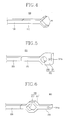
- Figure 3 is a perspective view showing a silicon carbide electric heating element in accordance with a first embodiment of the present invention
- Figure 4 is a cut perspective view showing a sectional area in longitudinal direction of a terminal part of Figure 3.
- the silicon carbide electric heating element 100 in accordance with a first embodiment of the present invention includes a terminal part 110 to which power is supplied, a heat generation part 120 connected to the terminal part 110 and generating heat, and a cooling part 130 formed at the terminal part 110 to cool the terminal part 110.
- the silicon carbide electric heating element is constructed such that heat is refrained from being transmitted to the terminal part 110 from the heat generation part 120 and transmitted heat can be quickly discharged in the air (in the atmosphere) so that the terminal part 110 may not be overheated during the operation of the electric heating element, and thus, the electric wire (W) can be directly connected to the wire engaging hole 111a of the terminal part 110.
- a cooling part 130 is provided in order to prevent overheating of the terminal part 110 of the silicon carbide electric heating element.
- a surface area enlarging protrusion 111 is formed in a pentagon shape at the end portion of the terminal part 110 to increase the surface area of the terminal part.
- formation of the surface area enlarging protrusion 111 at the terminal part 110 leads to enlargement of the overall surface area of the terminal part 110 and increase in a discharging amount of heat, so that the terminal part can be quickly cooled.
- a pentagonal cooling hole 132 is penetratingly formed at the surface area enlarging protrusion 111 to reduce the amount of transmission of heat transmitted from the terminal part 110.
- One or more pentagonal cooling hole 132 may be formed relying on the size of the surface area enlarging protrusion 131 or in consideration of cooling.
- the heat generation part 120 is heated to a high temperature.
- Heat transmission amount (Q1) coefficient of thermal conductivity (K1) * longitudinal surface area (A1) * temperature difference (T1) between heat generation part and terminal part
- the heat transmission amount (Q1) is in proportion to the longitudinal surface area (A1).
- the longitudinal surface area (A1) is reduced as much.
- the heat transmission amount (Q1) is reduced, and accordingly, the transmission amount (Q1) of heat transmitted from the heat generation part 120 to the terminal patt 110 is reduced.
- Reduction of the transmission amount (Q1) of heat transmitted from the heat generation part 120 to the terminal part 110 signifies that the high temperature heat of the heat generation part 120 is hardly transmitted to the terminal part 110, according to which the terminal part 110 is not overheated.
- Heat discharge amount (Q2) coefficient of heat convection (K2) * surface area (A2) of terminal part * temperature difference between terminal part and the atmosphere
- the heat transmission amount (Q2) is in proportion to the surface area (A2) of the terminal part.
- the electric wire (W0 can be directly connected to the terminal part 110.
- Figure 5 is a perspective view showing a silicon carbide electric heating element in accordance with a second embodiment of the present invention.
- a silicon carbide electric heating element 200 in accordance with a second embodiment of the present invention includes: a terminal part 210 to which power is supplied, a heat generation part 220 connected to the terminal part 210 and generating heat; and a cooling part 230 formed at the terminal part 210 to cool the terminal part 210.
- the silicon carbide electric heating element of the second embodiment of the present invention also includes the cooling part 230 in order to prevent overheat of the terminal part 210.
- a pentagonal surface area enlarging protrusion 231 is formed at an end portion of the terminal part 210 in order to increase the surface area of the terminal part 210.
- formation of the surface area enlarging protrusion 231 at the terminal part 210 leads to enlargement of the overall surface area of the terminal part 210 and increase in a discharging amount of heat, so that the terminal part can be quickly cooled.
- a circular cooling hole 232 is penetratingly formed at the side of the surface area enlarging protrusion 231.
- One or more circular cooling holes 232 can be formed depending on the size of the surface area enlarging protrusion 231 or in consideration of cooling.
- the silicon carbide electric heating element is constructed such that heat is refrained from being transmitted to the terminal part 210 from the heat generation part 220 and the transmitted heat, if any, can be quickly discharged in the air (in the atmosphere) so that the terminal part 210 may not be overheated during the operation of the electric heating element, and thus, the electric wire (W) can be directly connected to the wire engaging hole 211a of the terminal part 210.
- Figure 6 is a perspective view showing a silicon carbide electric heating element in accordance with a third embodiment of the present invention.
- a silicon carbide electric heating element 300 in accordance with a third embodiment of the present invention includes: a terminal part 310 to which power is supplied, a heat generation part 320 connected to the terminal part 310 and generating heat; and a cooling part 330 formed at the terminal part 310 to cool the terminal part 310.
- the silicon carbide electric heating element of the third embodiment of the present invention also includes the cooling part 330 in order to prevent overheat of the terminal part 310.
- a hexagonal surface area enlarging protrusion 311 is formed at the middle portion of the terminal part 310 in order to increase the surface area of the terminal part 310.
- formation of the surface area enlarging protrusion 311 at the terminal part 310 leads to enlargement of the overall surface area of the terminal part 310 and increase in a discharging amount of heat, so that the terminal part 310 can be quickly cooled.
- a hexagonal cooling hole 312 is penetratingly formed at the side of the surface area enlarging protrusion 311.
- One or more hexagonal cooling holes 312 can be formed depending on the size of the surface area enlarging protrusion 311 or in consideration of cooling.
- the silicon carbide electric heating element is constructed such that heat is refrained from being transmitted to the terminal part 310 from the heat generation part 320 and the transmitted heat, if any, can be quickly discharged in the air (in the atmosphere) so that the terminal part 310 may not be overheated during the operation of the electric heating element, and thus, the electric wire (W) can be directly connected to the wire engaging hole 311a of the terminal part 310.
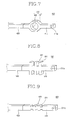
- Figure 7 is a perspective view showing a silicon carbide electric heating element in accordance with a fourth embodiment of the present invention.
- a silicon carbide electric heating element 400 in accordance with a fourth embodiment of the present invention includes: a terminal part 410 to which power is supplied, a heat generation part 420 connected to the terminal part 410 and generating heat; and a cooling part 430 formed at the terminal part 410 to cool the terminal part 410.
- the silicon carbide electric heating element of the fourth embodiment of the present invention also includes the cooling part 430 in order to prevent overheat of the terminal part 410.
- a pentagonal surface area enlarging protrusion 431 is formed at the middle portion of the terminal part 410 in order to increase the surface area of the terminal part 410.
- formation of the surface area enlarging protrusion 431 at the terminal part 410 leads to enlargement of the overall surface area of the terminal part 410 and increase in a discharging amount of heat, so that the terminal part 410 can be quickly cooled.
- a circular cooling hole 412 is penetratingly formed at the side of the surface area enlarging protrusion 431.
- One or more hexagonal cooling holes 412 can be formed depending on the size of the surface area enlarging protrusion 431 or in consideration of cooling.
- the silicon carbide electric heating element is constructed such that heat is refrained from being transmitted to the terminal part 410 from the heat generation part 420 and the transmitted heat, if any, can be quickly discharged in the air (in the atmosphere) so that the terminal part 410 may not be overheated during the operation of the electric heating element, and thus, the electric wire (W) can be directly connected to the wire engaging hole 411a of the terminal part 410.
- Figure 8 is a perspective view showing a silicon carbide electric heating element in accordance with a fifth embodiment of the present invention.
- a silicon carbide electric heating element 500 in accordance with a fifth embodiment of the present invention includes: a terminal part 510 to which power is supplied, a heat generation part 520 connected to the terminal part 510 and generating heat; and a cooling part 530 formed at the terminal part 510 to cool the terminal part 510.
- the silicon carbide electric heating element of the fifth embodiment of the present invention also includes the cooling part 530 in order to prevent overheat of the terminal part 510.
- a plurality of cooling protrusion 531 are formed at equal intervals at the middle portion of surface of the terminal part 510 in order to increase the overall surface area of the terminal part 510.
- the silicon carbide electric heating element is constructed such that heat transmitted from the heat generation part 520 to the terminal part 510 can be quickly discharged in the air (in the atmosphere) so that the terminal part 510 may not be overheated during the operation of the electric heating element, and thus, the electric wire (W) can be directly connected to the wire engaging hole 511a of the terminal part 510.
- Figure 9 is a perspective view showing a silicon carbide electric heating element in accordance with a sixth embodiment of the present invention.
- a silicon carbide electric heating element 600 in accordance with a sixth embodiment of the present invention includes: a terminal part 610 to which power is supplied, a heat generation part 620 connected to the terminal part 610 and generating heat; and a cooling part 630 formed at the terminal part 610 to cool the terminal part 610.
- the silicon carbide electric heating element of the sixth embodiment of the present invention also includes the cooling part 630 in order to prevent overheat of the terminal part 610.
- a plurality of cooling recesses 631 are formed at equal intervals at both sides of the terminal part 610 in order to reduce the transmission amount of heat transmitted from the heat generation part 620 to the terminal part 610.
- cooling recesses 631 at both sides of the terminal part 610 leads to enlargement of the surface area of the terminal part 610, so that the terminal part 610 can be quickly cooled.
- the silicon carbide electric heating element is constructed such that heat transmitted from the heat generation part 620 to the terminal part 610 can be quickly discharged in the air (in the atmosphere) so that the terminal part 610 may not be overheated during the operation of the electric heating element, and thus, the electric wire (W) can be directly connected to the wire engaging hole 611a of the terminal part 610.
- Figure 10 is a perspective view showing a silicon carbide electric heating element in accordance with a seventh embodiment of the present invention.
- a silicon carbide electric heating element 700 in accordance with a seventh embodiment of the present invention includes: a terminal part 710 to which power is supplied, a heat generation part 720 connected to the terminal part 710 and generating heat; and a cooling part 730 formed at the terminal part 710 to cool the terminal part 710.
- the silicon carbide electric heating element of the seventh embodiment of the present invention also includes the cooling part 730 in order to prevent overheat of the terminal part 710.
- the cooling part 730 consists of a cooling branch 731 and a wire engaging branch 732.
- the cooling branch and the wire engaging branch 732 are formed by cutting an end portion of the terminal part 710 in a horizontal direction.
- the cooling branch 731 includes a cooling hole 733, and the wire engaging branch 732 includes a wire engaging hole 711a.
- Dividing the end portion of the terminal part 710 into the cooling branch 731 and the wire engaging branch 732 leads to a rapid cooling of the cooling branch 731 by virtue of the cooling hole 733. Meanwhile, in case of the wire engaging branch 732, since its sectional area in the longitudinal direction is small compared to that of the cooling branch 731, heat is less transmitted thereto from the heat generation part 720. Accordingly, a damage to the electric wire can be effectively prevented.
- the silicon carbide electric heating element of the present invention has the following advantage.
- the sectional area of the terminal part is reduced to refrain heat transmission from the silicon carbide heat generation part to the terminal part or the overall surface area of the terminal part is increased to quickly cool the terminal part. Therefore, since the terminal part is not heated, the electric wire can be directly connected for use to the terminal part without an additional connection member.
Landscapes
- Resistance Heating (AREA)
- Air-Conditioning For Vehicles (AREA)
Abstract
Description
Claims (13)
- A silicon carbide electric heating element comprising:a terminal part to which power is supplied;a heat generation part connected to the terminal part and generating heat; anda cooling part formed at the terminal part to cool the terminal part.
- The heating element of claim 1, wherein the cooling part is a surface area enlarging protrusion formed at the terminal part in order to increase the surface area.
- The heating element of claim 2, wherein the surface area enlarging protrusion is formed at an end portion of the terminal part.
- The heating element of claim 2, wherein the surface area enlarging protrusion is formed at the middle portion of the terminal part.
- The heating element of claim 2, wherein the surface area enlarging protrusion is polygonal.
- The heating element of claim 2, wherein a cooling hole is penetratingly formed at the side of the surface area enlarging protrusion in order to reduce a transmission amount of heat transmitted from the heat generation part to the terminal part.
- The heating element of claim 6, wherein at least one or more cooling holes are formed.
- The heating element of claim 1, wherein the cooling part is a cooling protrusion formed at the surface of the terminal part.
- The heating element of claim 8, wherein a plurality of cooling protrusion are formed.
- The heating element of claim 9, wherein the cooling protrusions are formed at equal intervals.
- The heating element of claim 1, wherein the cooling part is a cooling recess formed at both sides of the terminal part 610 in order to reduce a transmission amount of heat transmitted from the heat generation part to the terminal part.
- The heating element of claim 11, wherein a plurality of cooling recesses are formed at equal intervals.
- The heating element of claim 1, wherein the cooling part comprises a cooling branch formed and a wire engaging branch which are dividedly formed by cutting an end portion of the terminal part.
Applications Claiming Priority (2)
| Application Number | Priority Date | Filing Date | Title |
|---|---|---|---|
| KR2002019261 | 2002-04-09 | ||
| KR10-2002-0019261A KR100474333B1 (en) | 2002-04-09 | 2002-04-09 | Structure of terminal for electric heater |
Publications (2)
| Publication Number | Publication Date |
|---|---|
| EP1353533A2 true EP1353533A2 (en) | 2003-10-15 |
| EP1353533A3 EP1353533A3 (en) | 2006-07-05 |
Family
ID=28450130
Family Applications (1)
| Application Number | Title | Priority Date | Filing Date |
|---|---|---|---|
| EP03003406A Withdrawn EP1353533A3 (en) | 2002-04-09 | 2003-02-14 | Silicon carbide electric heating element |
Country Status (5)
| Country | Link |
|---|---|
| US (1) | US20030189036A1 (en) |
| EP (1) | EP1353533A3 (en) |
| JP (1) | JP2003303665A (en) |
| KR (1) | KR100474333B1 (en) |
| CN (1) | CN1215738C (en) |
Families Citing this family (5)
| Publication number | Priority date | Publication date | Assignee | Title |
|---|---|---|---|---|
| JP2006302887A (en) * | 2005-04-20 | 2006-11-02 | Ngk Insulators Ltd | Power feeding member and heating device |
| CN101562914B (en) * | 2008-04-17 | 2011-05-18 | 泰州市环能硅碳棒制造有限公司 | Production technology for cold end part of silicon carbide rod |
| DE102010012079A1 (en) * | 2010-03-19 | 2011-09-22 | Centrotherm Thermal Solutions Gmbh + Co. Kg | Heating device for thermal treating of semiconductor substrate in quartz tube, has connection element including three portions with respective cross section areas, where area of one of portions is smaller than that of other two portions |
| CN107155227A (en) * | 2017-07-13 | 2017-09-12 | 贵州仙劲锌业有限公司 | A kind of high power high-temperature heater of suitable multiple atmosphere |
| JP2024118992A (en) * | 2023-02-21 | 2024-09-02 | 国立大学法人東海国立大学機構 | Electrode structure of three-dimensional electric heater |
Family Cites Families (19)
| Publication number | Priority date | Publication date | Assignee | Title |
|---|---|---|---|---|
| CH101501A (en) * | 1922-10-17 | 1923-09-17 | Oerlikon Maschf | Terminal for electrical heating conductors laid in protective covers. |
| US2745928A (en) * | 1952-10-06 | 1956-05-15 | American Electro Metal Corp | Heater bodies and their production |
| US3252827A (en) * | 1958-11-05 | 1966-05-24 | Carborundum Co | Refractory carbide bodies and method of making them |
| US3969696A (en) * | 1973-09-19 | 1976-07-13 | Wolfe Denis G | Refractory resistor with supporting terminal |
| US3875477A (en) * | 1974-04-23 | 1975-04-01 | Norton Co | Silicon carbide resistance igniter |
| US4058789A (en) * | 1976-04-05 | 1977-11-15 | The Carborundum Company | Electrical connector |
| US4449039A (en) * | 1981-09-14 | 1984-05-15 | Nippondenso Co., Ltd. | Ceramic heater |
| US4486651A (en) * | 1982-01-27 | 1984-12-04 | Nippon Soken, Inc. | Ceramic heater |
| US5045237A (en) * | 1984-11-08 | 1991-09-03 | Norton Company | Refractory electrical device |
| JPH0713907B2 (en) * | 1985-09-26 | 1995-02-15 | 日本電装株式会社 | Ceramic Heater |
| US4804823A (en) * | 1986-07-31 | 1989-02-14 | Kyocera Corporation | Ceramic heater |
| DE68906042T2 (en) * | 1988-02-06 | 1993-07-29 | Shinagawa Refractories Co | ZIRCONIUM OXIDE HEATING ELEMENT. |
| US5449886A (en) * | 1993-03-09 | 1995-09-12 | University Of Cincinnati | Electric heating element assembly |
| US5804092A (en) * | 1995-05-31 | 1998-09-08 | Saint-Gobain/Norton Industrial Ceramics Corporation | Modular ceramic igniter with metallized coatings on the end portions thereof and associated terminal socket |
| JPH10213324A (en) * | 1997-01-30 | 1998-08-11 | Jidosha Kiki Co Ltd | Metallic wire jointing method, ceramic heater and manufacturing method thereof |
| FR2780845B1 (en) * | 1998-07-06 | 2000-08-11 | Electricite De France | HEATING ELECTRIC RESISTOR FOR ELECTRIC OVEN AND METHOD FOR MANUFACTURING SUCH A RESISTOR |
| US6078028A (en) * | 1999-02-19 | 2000-06-20 | Saint-Gobain Industrial Ceramics, Inc. | Solderless ceramic igniter having a leadframe attachment |
| JP2000286038A (en) * | 1999-03-31 | 2000-10-13 | Ngk Insulators Ltd | Bonding structure between ceramic heater and electrode terminal and bonding method |
| US6396028B1 (en) * | 2001-03-08 | 2002-05-28 | Stephen J. Radmacher | Multi-layer ceramic heater |
-
2002
- 2002-04-09 KR KR10-2002-0019261A patent/KR100474333B1/en not_active Expired - Fee Related
-
2003
- 2003-02-14 EP EP03003406A patent/EP1353533A3/en not_active Withdrawn
- 2003-02-24 JP JP2003045867A patent/JP2003303665A/en active Pending
- 2003-02-26 US US10/372,784 patent/US20030189036A1/en not_active Abandoned
- 2003-04-08 CN CNB031095046A patent/CN1215738C/en not_active Expired - Fee Related
Also Published As
| Publication number | Publication date |
|---|---|
| EP1353533A3 (en) | 2006-07-05 |
| JP2003303665A (en) | 2003-10-24 |
| US20030189036A1 (en) | 2003-10-09 |
| CN1450834A (en) | 2003-10-22 |
| CN1215738C (en) | 2005-08-17 |
| KR20030080567A (en) | 2003-10-17 |
| KR100474333B1 (en) | 2005-03-08 |
Similar Documents
| Publication | Publication Date | Title |
|---|---|---|
| CN201655931U (en) | Heating structure and device applied to battery and auxiliary module | |
| JP5365413B2 (en) | Circuit breaker | |
| JP2018147607A (en) | Heat transfer device for battery pack | |
| WO2022089007A1 (en) | Cooking device | |
| EP1353533A2 (en) | Silicon carbide electric heating element | |
| WO2000041261A3 (en) | Liquid-cooled fuel cell battery comprising an integrated heat exchanger | |
| CN204968132U (en) | Ceramic heater with increased wind area | |
| JP2018503217A (en) | Thermal management in the field of e-mobility | |
| US10182470B2 (en) | Ceramic heater having enlarged windward area | |
| JP2005012991A (en) | Ac adapter | |
| US20030184429A1 (en) | Resistor for driving motor for air conditioner blower | |
| KR102333290B1 (en) | Battery module with direct cooling of tap | |
| JP2018195844A (en) | heatsink | |
| KR100665048B1 (en) | Rapid cooling structure of motor using heat pipe | |
| JP4081764B2 (en) | Optimal temperature controlled fuel cell | |
| EP2494649B1 (en) | Thermally efficient dielectric resonator support | |
| TWM511174U (en) | Ceramic heater with increased receiving wind area | |
| CN217134879U (en) | Temperature-monitored volume Bragg grating device and semiconductor laser | |
| JPH0734392B2 (en) | PTC thermistor heating device | |
| CN220067717U (en) | PTC heater structure | |
| KR101373122B1 (en) | A Heat Exchanger using Thermoelectric Modules | |
| JP2009218137A (en) | Heat exchanger | |
| CN218069632U (en) | Fuse with additional heat radiating device | |
| JP3200249U (en) | Ceramic heater with increased wind receiving area | |
| JP2016184639A (en) | Heat dissipation device |
Legal Events
| Date | Code | Title | Description |
|---|---|---|---|
| PUAI | Public reference made under article 153(3) epc to a published international application that has entered the european phase |
Free format text: ORIGINAL CODE: 0009012 |
|
| AK | Designated contracting states |
Kind code of ref document: A2 Designated state(s): AT BE BG CH CY CZ DE DK EE ES FI FR GB GR HU IE IT LI LU MC NL PT SE SI SK TR |
|
| AX | Request for extension of the european patent |
Extension state: AL LT LV MK RO |
|
| PUAL | Search report despatched |
Free format text: ORIGINAL CODE: 0009013 |
|
| AK | Designated contracting states |
Kind code of ref document: A3 Designated state(s): AT BE BG CH CY CZ DE DK EE ES FI FR GB GR HU IE IT LI LU MC NL PT SE SI SK TR |
|
| AX | Request for extension of the european patent |
Extension state: AL LT LV MK RO |
|
| 17P | Request for examination filed |
Effective date: 20060914 |
|
| 17Q | First examination report despatched |
Effective date: 20070207 |
|
| AKX | Designation fees paid |
Designated state(s): DE FR GB IT |
|
| STAA | Information on the status of an ep patent application or granted ep patent |
Free format text: STATUS: THE APPLICATION IS DEEMED TO BE WITHDRAWN |
|
| 18D | Application deemed to be withdrawn |
Effective date: 20080618 |