EP1353518A1 - Process and system for generating stereoscopic images from monocular images - Google Patents
Process and system for generating stereoscopic images from monocular images Download PDFInfo
- Publication number
- EP1353518A1 EP1353518A1 EP02425218A EP02425218A EP1353518A1 EP 1353518 A1 EP1353518 A1 EP 1353518A1 EP 02425218 A EP02425218 A EP 02425218A EP 02425218 A EP02425218 A EP 02425218A EP 1353518 A1 EP1353518 A1 EP 1353518A1
- Authority
- EP
- European Patent Office
- Prior art keywords
- image
- pixels
- stereoscopic effect
- monocular image
- movement
- Prior art date
- Legal status (The legal status is an assumption and is not a legal conclusion. Google has not performed a legal analysis and makes no representation as to the accuracy of the status listed.)
- Withdrawn
Links
Images


Classifications
-
- H—ELECTRICITY
- H04—ELECTRIC COMMUNICATION TECHNIQUE
- H04N—PICTORIAL COMMUNICATION, e.g. TELEVISION
- H04N13/00—Stereoscopic video systems; Multi-view video systems; Details thereof
- H04N13/20—Image signal generators
- H04N13/261—Image signal generators with monoscopic-to-stereoscopic image conversion
-
- H—ELECTRICITY
- H04—ELECTRIC COMMUNICATION TECHNIQUE
- H04N—PICTORIAL COMMUNICATION, e.g. TELEVISION
- H04N13/00—Stereoscopic video systems; Multi-view video systems; Details thereof
- H04N13/10—Processing, recording or transmission of stereoscopic or multi-view image signals
- H04N13/106—Processing image signals
- H04N13/122—Improving the 3D impression of stereoscopic images by modifying image signal contents, e.g. by filtering or adding monoscopic depth cues
-
- H—ELECTRICITY
- H04—ELECTRIC COMMUNICATION TECHNIQUE
- H04N—PICTORIAL COMMUNICATION, e.g. TELEVISION
- H04N13/00—Stereoscopic video systems; Multi-view video systems; Details thereof
- H04N13/10—Processing, recording or transmission of stereoscopic or multi-view image signals
- H04N13/106—Processing image signals
- H04N13/128—Adjusting depth or disparity
-
- H—ELECTRICITY
- H04—ELECTRIC COMMUNICATION TECHNIQUE
- H04N—PICTORIAL COMMUNICATION, e.g. TELEVISION
- H04N13/00—Stereoscopic video systems; Multi-view video systems; Details thereof
- H04N13/20—Image signal generators
- H04N13/204—Image signal generators using stereoscopic image cameras
- H04N13/239—Image signal generators using stereoscopic image cameras using two 2D image sensors having a relative position equal to or related to the interocular distance
-
- H—ELECTRICITY
- H04—ELECTRIC COMMUNICATION TECHNIQUE
- H04N—PICTORIAL COMMUNICATION, e.g. TELEVISION
- H04N13/00—Stereoscopic video systems; Multi-view video systems; Details thereof
- H04N13/20—Image signal generators
- H04N13/286—Image signal generators having separate monoscopic and stereoscopic modes
-
- H—ELECTRICITY
- H04—ELECTRIC COMMUNICATION TECHNIQUE
- H04N—PICTORIAL COMMUNICATION, e.g. TELEVISION
- H04N13/00—Stereoscopic video systems; Multi-view video systems; Details thereof
- H04N2013/0074—Stereoscopic image analysis
- H04N2013/0081—Depth or disparity estimation from stereoscopic image signals
Definitions
- the present invention relates to the art of stereoscopic vision, and in particular tackles the problem of reconstructing the stereoscopic vision of objects from the availability of monocular vision of these objects and the relative depth map.
- the photo When a photograph is acquired, for example using a camera, the photo provides a two-dimensional image of the scene in which the depth information and distance between objects (or the different regions of the scene) are not present. By looking at these two-dimensional images, an observer may virtually reconstruct the depth information through previously acquired knowledge of the world represented in this photo.
- retinal disparity can be easily understood with reference to a simple experiment: hold the thumb of one hand in front of your face and observe it.
- Disparity is the distance, in a horizontal direction, between the corresponding right and left points of the superimposed retinic images.
- the corresponding points of the retinal images of an object on which the eyes are converged have zero disparity.
- Retinal disparity is caused by the fact that each eye sees the world from a different view point. Eyes are, on average in adults, spaced apart by about 64 mm (this distance between the right and left eyes is called base line or interocular distance).
- Disparity is processed by the eye-brain system into a single image of the visual world.
- the capacity of the mind to unite two different images, even if similar, into one single image is called fusion, and the resulting sense of depth is called stereopsis.
- parallax and disparity are similar entities, with the difference given by the fact that the parallax is measured on the screen and the disparity is measured on the retina. It is the parallax that produces retinal disparity and the disparity in turn which produces stereopsis. Parallax may also be given in terms of angular measurements, which connects it to the disparity considering the distance of the observer from the viewing screen. Parallax is an important entity, as it produces the stereoscopic sense of depth.
- Projection for the left eye LE is to the left and projection for the right eye RE is to the right.
- the distance between the right and left projections of the eye is called horizontal parallax PO.
- the maximum positive parallax PO is obtained when the object is infinite. At this point, the horizontal parallax PO is equal to the base line or interocular distance.
- the distance between the objectives used to take a stereoscopic photograph is called interaxial distance, as regards the axes of the lenses.
- the axis of the objective is the line that can be drawn through the optic centre of the objective and is perpendicular to the plane of the surface on which the image is formed.
- the interaxial distance may be considered as coinciding with the interocular distance when the eye is considered as an image acquiring system.
- WO-A-01/39512 describes a device destined to convert a two-dimensional video image into a three-dimensional video image.
- the device comprises means to correct the parallax of each area calculated by means to calculate the parallax on the basis of the magnitude of a moving vector.
- This solution is used to avoid the disadvantage caused by the fact that the stereoscopic sense of the video signal obtained by conversion is strongly influenced, with the same input video signal, as a function of the criteria employed to convert the video signal.
- the document in question refers to prior art procedures such as MTD (Modified Time Difference) and CID (Computed Image Depth).
- a depth estimate When a depth estimate is converted into a parallax, the estimate in question is subjected to a conversion of the distances scale so as to suppress the distortion of the image resulting from conversion and to determine, at least at tentative level, a target phase for each calculation area of the parallax.
- a dynamic field is identified in which the differences in phase between the parallax calculation areas are within an admissible change of distortion, producing a conversion of the distances scale, also determining, again at tentative level, a target phase and repeating this processing sequence.
- the object of the invention is thus to provide a solution for the generation of stereoscopic images from monocular images capable of giving rise to extremely satisfactory results from the viewpoint of quality. All this giving rise to a processing system architecture that allows easy implementation at a physical level, in particular at the level of hardware devices.
- the invention also relates to the relative system.
- the solution according to the invention allows the generation of the stereoscopic pair from a single source image of the monocular type and from the relative depth information.
- This image or depth map is an image with levels of grey (for example with values from 0 to 255 - therefore on eight bits), which represents the depth of each object within the source image.
- the conjunction of the source image and the depth map allow reconstruction of the binocular view, thus producing a three-dimensional effect.
- a final filtering treatment makes it possible to solve the "occlusions", generated by introducing the parallax effect, without however introducing visible and/or bothersome artefacts.
- This process is preferably performed on the basis of all the three-dimensional coordinates of the objects inside the image.
- Each object, each dot, each figure is then identified, divided, separated, calculated and so on, also knowing the parameters of the acquisition system (for example the parameters of the camera or television camera).
- the parameters of the acquisition system for example the parameters of the camera or television camera.
- the solution according to the invention envisages the performance of three classes of operations: acquisition, reconstruction (or processing) and viewing.
- the solution according to the invention is susceptible to prescind from the input information referring to the concept of the depth map, which is susceptible to provide at least the form, the position of the objects and the relative depth in the scene.
- this selection may include the choice of anaglyphs.
- the first step is to define the source view point: in other words, to decide if the two final images (right and left) must be recreated from nothing having that source of reference, or if the source image is to be exactly one of the final images while only the other is to be reconstructed from it.
- the first action is the one most suited for the final phase of reconstruction by means of applying the parallax.
- this does not imply a restriction or differentiation of the conversion problem.
- the present invention hereunder proposes a solution to limit visibility of the artefacts, not by using special functions to mask these but by variable modification of a reduction/enlargement factor of the depth perception inside the viewing device.
- the first two elements are useful in order to generate images with dimensions congruous with the device utilized for viewing.
- the third element can be easily calculated having the first two elements and using the viewing specifications of the human eye.
- the fourth (namely the depth of the objects) is instead an essential element on which reconstruction of the three-dimensional environment from the two-dimensional projection is based.
- the present invention utilizes the concept of depth map for this purpose.
- the depth map in practice the link existing between two-dimensional and three-dimensional worlds (or what is sometimes defined two-and-a-half dimensions or 2D 1 ⁇ 2), is a mapping of the objects present in an image in relation to their spatial position.
- This mapping may alternatively have two meanings.
- the first identifies the exact correspondence of the space of each dot of the image, and in this case may be defined as depth map.
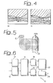
- this is an image with different levels of grey in which each area reproduced with a specific level of grey (shown in figure 4 with different sectioning) identifies the positioning, within the extent of the image, of objects or of a group of objects t found in a certain distance range in relation to the observation point.
- both images of figure 4 reproduce different depth maps of an image of a mountain panorama (essentially the view of a valley).
- the overall effect that can be deduced by observing the depth map is almost similar to the effect perceivable by observing a group of stage settings or by observing a mountain landscape at daybreak or dusk in conditions in which the reduced level of luminosity makes chromatic information difficult to perceive and, at the same time, the grazing illumination of the sun low on the horizon highlights the staggering, on various subsequent perspective planes, of the raised areas included in the landscape.
- the phenomenon is linked to so-called depth perception and is inversely proportional to distance from the object in question. Therefore the problem is posed of how to correctly define a depth map that complies with this rule.
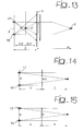
- Figure 5 illustrates a typical effect of perception of three-dimensional or 3D space, identifying, on the one hand, equidistant levels of depth EL and the relative perception PER.
- Figure 5 defines several levels of depth equidistant from one another, so that the initial rule is not violated. This also means that a real depth map can be emulated with an appropriate disparity map. In other words, even if we do not know the real three-dimensional position of the objects, but by judiciously distributing each object on different levels equidistant from one another, it is possible to generate -- a -- depth effect very similar to the real one: in this respect, it must again be mentioned that the object set by the solution according to the invention is to reconstruct three-dimensionality of the scene and not exactly the real one.
- This task may be facilitated by analysis of the initial image in the temporal domain.
- this analysis might never reveal the original information that we are attempting to reconstruct. This is due, for example, to the fact that a certain object (or usually a certain portion of this) might never be visible during the entire sequence, irrespective of the number of images considered.
- a technique that may be suggested to decrease the presence and/or visibility of these artefacts is one that, by limiting as much as possible a magnitude of the holes on the final images and maintaining the visual three-dimensional effect, fills or fills in these holes or gaps with the original information in the homologous positions.
- Figure 6 illustrates in the form of a block diagram the architecture of a system for the reconstruction of a three-dimensional scene according to the criteria set forth above.
- the aforesaid system indicated as a whole with 10, comprises corresponding modules that perform the following functions:
- Module 12 is composed mainly of data memorizing structures (of the known kind) in which the two-dimensional images destined to be placed at the disposal of the other processing blocks present in the system are loaded. No general limits are set on the quantity of the images that can be loaded.
- a typical example of these processing methods is given by the techniques for processing images based on the use of neural networks which, for their matrix structure, are suitable to be coupled directly to image sensors which also have a matrix structure.
- Module 14 implements acquisition of the depth map connected to the image or images input into the system through module 12. As already mentioned, the present invention does not specifically relate to the generation of the aforesaid depth map, which may be made available to the system described herein employing any prior art solution for this purpose. Clearly, the quantity of depth data loaded in module 14 must correspond to the quantity of source data loaded in module 12.
- One of the parameters to be considered in three-dimensional reconstruction is correlation between the quantity of parallax to obtain the three-dimensional effect and the quantity of pixels corresponding to it.
- the parallax value as a function of the interocular distance must be converted into a specific quantity of pixels to move data horizontally to the right and left. It is therefore necessary to determine the correct conversion function that considers the two systems different to value the pixel/distance ratio (usually expressed in millimetres).
- the images will be viewed on the dedicated screen, with a fixed dimension and fixed resolution. It may thus be assumed that, by observing the three-dimensional image with the full screen, the image must also have the same dimension and resolution as the video. If this is not the case, the final image must be processed (according to prior art which does not require to be described herein) so that it is then aligned with these values.
- Pixel/mm (X px .Y px ) / (W mm .H mm ) where the input image has [X:Y] pixels and where the final screen has the dimensions [W:H].
- the original pixel and its replica must be moved (horizontally) by a quantity defined by the parallax value to be applied.
- the diagram in figure 7 illustrates, in the form of a functional block diagram, the criteria used to calculate the final parallax.
- references 26 and 28 illustrate the data (which can be seen as data files) containing the information relative to the interocular distance and the decrease in depth (file 26) and the image length, the image width and the diagonal dimension of the video (file 28).
- the block 30 represents the functional module which determines the distance and resolution, in particular generating the information relative to the minimum user-screen distance (intended as the minimum distance at which the image is viewed on the screen comfortably for the human vision system, distances greater than this minimum value increase the comfort of viewing but give increasingly less depth perception) and the pixels/millimetres ratio seen previously.
- a module indicated with 32 calculates, on the basis of the data contained in file 26, the parallax, intended as maximum parallax.
- the block 34 indicates the module destined to act as parallax motor destined to feed towards a module acting as movement motor, indicated with 36, the movement information (right left) relative to the parallax.
- the module 36 generates the left image LI and the right image RI destined to be sent to modules 18 and 20 of figure 6.
- the block or module 30 assesses two important parameters: the minimum distance recommended to the user to view the screen in comfort and the resolution of the image as pixel/millimetre ratio.
- Block or module 32 assesses the maximum parallax value M that can be obtained in relation to the interocular distance, indicated with B, and to the depth effect desired (F(D)).
- Block 36 is instead the true movement motor, which must take account of the distribution of the total parallax value.
- the parallax value must also be divided into two parts.
- Each of these parts generally corresponds to a fraction of the overall movement and can therefore be either extremely different from or equal to each other (for example, by being equal to half of the overall movement).
- a black edge is also present due to the lack of information to enter in the corresponding lateral bands.
- the dimension of this edge depends principally on the parallax. In particular, it depends on the maximum parallax value of those pixels that do not fall inside the image.
- the dimension of the edges that remain blacked does not depend on the value of the maximum parallax applied to the image, but on the maximum parallax that the pixels may have.
- the maximum parallax defines the extent of the maximum depth effect of the screen.
- this value will never be reached. Therefore, there is a direct and proportional dependence with the content of the depth map.
- Figure 11 illustrates an example in which, after a left movement, it is no longer possible to establish and state with certainty which values the pixels to the right of D and to the left of E must have.
- the depth map associated to the source. As has already been seen, the depth map forms the connection between the two-dimensional source at the three-dimensional output.
- the object sought here is not to reconstruct the natural three-dimensional effect, but to manage a three-dimensional effect, capable of managing all types of map, thus capable of manipulating the three-dimensional effect as required: this feature is of particular importance, for example, in entertainment applications or medical and scientific applications.
- the value of the parallax can be seen as a function of the interocular distance B. This is mainly true when it is asserted that the parallax cannot be greater than B in the cases in which:
- variable distance can be defined, with a minimum value equal to D, at which the observer must be positioned from the screen S, while it is possible to define the depth inside the screen as variable.
- the next step is to define the best scale function to associate to each value of the depth map the corresponding parallax value M to be associated to each pixel.
- the maximum parallax is associated to the objects furthest away, while the minimum parallax is associated to those nearest.
- the minimum value for N is 2 as a higher parallax value is not possible. Therefore the maximum parallax and the depth of the screen are made to depend on the reduction value N.
- a reference value of N to obtain comfortable three-dimensional vision can be obtained through experimental tests.
- the variability of the depth effect is connected to the programmable reduction factor N of the three-dimensional effect desired.
- the value N has a fundamental role in creating the occlusions in the construction process of the two right and left images so that as N decreases there is an increase in the magnitude of the holes between originally adjacent objects and an increase in the dimension of the lateral edge of the image that is blacked.
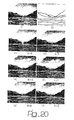
- Figure 20 indicates various possible results of three-dimensional reconstruction of an original image a) from a depth map indicated with b).
- N the greater the maximum parallax is, causing less comfortable three-dimensional vision of the anaglyph. It is obvious that, as a function of the application, it is possible to choose a correct compromise between the value of N and a comfortable three-dimensional vision, in particular as regards the non-perception of holes and gaps.
Abstract
To generate, from at least on monocular image
(12), at least one image with stereoscopic effect (18,
20), a depth map is provided (14) of said monocular
image (a). The depth map in question defines a mapping
of the objects present in the monocular image in
relation to their spatial position in the direction of
depth. For the pixels included in the monocular image
and as a function of the depth map, respective parallax
values are determined (16) indicative of a respective
quantity of movement by which each pixel must be moved
in the image with stereoscopic effect (18, 20) in
relation to the monocular image (12). A movement
corresponding to the respective quantity thus defined
is then applied to the pixels of the monocular image
(12), if necessary dividing it between two images of a
stereoscopic pair (18, 20). Post-processing (22) of the
image generated is also envisaged, to eliminate
artifacts such as superimposed areas between moved
pixels, a lateral edge of the image or gaps between
objects included in said image generated as a result of
the aforesaid movement of pixels.
Description
The present invention relates to the art of
stereoscopic vision, and in particular tackles the
problem of reconstructing the stereoscopic vision of
objects from the availability of monocular vision of
these objects and the relative depth map.
When a photograph is acquired, for example using a
camera, the photo provides a two-dimensional image of
the scene in which the depth information and distance
between objects (or the different regions of the scene)
are not present. By looking at these two-dimensional
images, an observer may virtually reconstruct the depth
information through previously acquired knowledge of
the world represented in this photo.
Various factors come into play in this
reconstruction mechanism, such as retinal disparity,
parallax and interaxial distance.
The concept of retinal disparity can be easily
understood with reference to a simple experiment: hold
the thumb of one hand in front of your face and observe
it.
When observation is concentrated on the thumb, the
eyes of the observer converge on this thumb, so that
the optical axes of both eyes go through the thumb.
Various muscles of the head move the eyes to obtain
this result, arranging the images of the thumb on each
fovea or central part of each retina. If, continuing to
make the eyes converge on the thumb, the background is
observed, it is seen that the background seems to
double.
However, if the eyes are concentrated on the
background, the eyes converge on the background and it
is now the thumb that is seen with a double image.
If the images that form on the retina of the right
eye and on the retina of the left eye could be taken
and superimposed, approximately the same scene would be
obtained almost superimposed (right and left
perspective view points), and the difference between
these images is called "disparity". Disparity is the
distance, in a horizontal direction, between the
corresponding right and left points of the superimposed
retinic images. The corresponding points of the retinal
images of an object on which the eyes are converged
have zero disparity.
For further information on the principles and
criteria at the basis of stereoscopic vision it is
useful to refer to the website
http://iglasses.weirdoz.org/docs/handbook.pdf
corresponding to the Stereographic Developers'
Handbook.
Retinal disparity is caused by the fact that each
eye sees the world from a different view point. Eyes
are, on average in adults, spaced apart by about 64 mm
(this distance between the right and left eyes is
called base line or interocular distance).
Disparity is processed by the eye-brain system
into a single image of the visual world. The capacity
of the mind to unite two different images, even if
similar, into one single image is called fusion, and
the resulting sense of depth is called stereopsis.
Other important concepts in order to understand
the mechanism of stereoscopic vision are parallax and
disparity. These are similar entities, with the
difference given by the fact that the parallax is
measured on the screen and the disparity is measured on
the retina. It is the parallax that produces retinal
disparity and the disparity in turn which produces
stereopsis. Parallax may also be given in terms of
angular measurements, which connects it to the
disparity considering the distance of the observer from
the viewing screen. Parallax is an important entity, as
it produces the stereoscopic sense of depth.
The different types of parallax that can be
encountered when observing a viewing screen are
classified hereunder.
In the case in which the object is behind the
projection plane the conditions represented in figure 1
are found.
In this figure, the point to project, indicated
with P, if found "behind" the projection plane S, or on
the opposite side in relation to the left and right
eyes, indicated with LE and RE respectively.
Projection for the left eye LE is to the left and
projection for the right eye RE is to the right. The
distance between the right and left projections of the
eye is called horizontal parallax PO. As the
projections are found on the same side as the eyes, it
is called positive parallax. The maximum positive
parallax PO is obtained when the object is infinite. At
this point, the horizontal parallax PO is equal to the
base line or interocular distance.
If the object or point to project P is positioned
further forward in relation to the projection plane S
the conditions represented in figure 2 are produced.
Projection for the left eye LE is to the right and
projection for the RE eye is to the left. In this case
conditions of negative horizontal parallax OP are
found. A negative horizontal parallax OP equal to the
base line or interocular distance is obtained when the
object is at a distance equal to half the distance
between the projection plane S and the centre of the
axis of the eyes. When the object moves towards the
observer the negative horizontal parallax OP increases
infinitely.
If an object is on the projection plane S (figure
3), relative projection on the focal plane coincides
for both the left LE and right RE eyes. The homologous
points of the two images correspond exactly or are one
on top of the other. When the eyes of the observer are
looking at the viewing screen S (or the eyes converge
on the plane of the screen) images are being observed
with zero parallax.
In this case too, for more detailed information
reference can be made to the website
http://astronomy.swind.edu.au/pbourke/stereographics/st
ereorender and in particular to the Calculating Stereo
Pairs section.
The distance between the objectives used to take a
stereoscopic photograph is called interaxial distance,
as regards the axes of the lenses. The axis of the
objective is the line that can be drawn through the
optic centre of the objective and is perpendicular to
the plane of the surface on which the image is formed.
Whether this is a real objective or the
construction of an objective is being used to generate
an image generated by the computer, the concept is the
same. If the objectives are near, the stereoscopic
effect of depth is reduced. In the extreme case in
which the two objectives (and axes) coincide, the final
result is a planar image. By increasing the distance
between the objectives, both the parallax and the
stereoscopic effect increase. In this regard reference
may again be made to the Stereographic Developers'
Handbook website, mentioned above.
In general the interaxial distance may be
considered as coinciding with the interocular distance
when the eye is considered as an image acquiring
system.
In numerous applicative contexts (for example in
medicinal and scientific, physical and constructional
applications, and in the entertainment, information and
education sectors) there is an interest to produce, as
a characterizing element for viewing, a three-dimensional
effect, in particular obtaining this effect
on a viewing device, such as a screen of various types,
which itself has two-dimensional or, at least,
substantially two-dimensional properties.
For example, WO-A-01/39512 describes a device
destined to convert a two-dimensional video image into
a three-dimensional video image. The device comprises
means to correct the parallax of each area calculated
by means to calculate the parallax on the basis of the
magnitude of a moving vector. This solution is used to
avoid the disadvantage caused by the fact that the
stereoscopic sense of the video signal obtained by
conversion is strongly influenced, with the same input
video signal, as a function of the criteria employed to
convert the video signal. In particular, the document
in question refers to prior art procedures such as MTD
(Modified Time Difference) and CID (Computed Image
Depth). When a depth estimate is converted into a
parallax, the estimate in question is subjected to a
conversion of the distances scale so as to suppress the
distortion of the image resulting from conversion and
to determine, at least at tentative level, a target
phase for each calculation area of the parallax. A
dynamic field is identified in which the differences in
phase between the parallax calculation areas are within
an admissible change of distortion, producing a
conversion of the distances scale, also determining,
again at tentative level, a target phase and repeating
this processing sequence.
In more generic terms, the general problem linked
to these conversion or construction techniques is given
by the need to reconstruct the correct retinal
disparity of the objects present in the scene, on the
basis of the interaxial distance of the observer and
the desired parallax effect.
The object of the invention is thus to provide a
solution for the generation of stereoscopic images from
monocular images capable of giving rise to extremely
satisfactory results from the viewpoint of quality. All
this giving rise to a processing system architecture
that allows easy implementation at a physical level, in
particular at the level of hardware devices.
According to the present invention, this object is
attained thanks to a process with the characteristics
indicated specifically in the claims hereunder.
The invention also relates to the relative system.
In brief, in the currently preferred embodiment,
the solution according to the invention allows the
generation of the stereoscopic pair from a single
source image of the monocular type and from the
relative depth information.
This image or depth map is an image with levels of
grey (for example with values from 0 to 255 - therefore
on eight bits), which represents the depth of each
object within the source image. The conjunction of the
source image and the depth map allow reconstruction of
the binocular view, thus producing a three-dimensional
effect.
A final filtering treatment makes it possible to
solve the "occlusions", generated by introducing the
parallax effect, without however introducing visible
and/or bothersome artefacts.
This process is preferably performed on the basis
of all the three-dimensional coordinates of the objects
inside the image.
Each object, each dot, each figure is then
identified, divided, separated, calculated and so on,
also knowing the parameters of the acquisition system
(for example the parameters of the camera or television
camera).
These data can be used to reconstruct the world in
three dimensions with the real distance between
objects, their occlusions and reproduction of the
distortions of these objects.
The lack of the specific information described
above is solved by the availability of the aforesaid
depth map.
In the currently preferred embodiment, the
solution according to the invention envisages the
performance of three classes of operations:
acquisition, reconstruction (or processing) and
viewing.
With regard to the acquisition phase, the solution
according to the invention is susceptible to prescind
from the input information referring to the concept of
the depth map, which is susceptible to provide at least
the form, the position of the objects and the relative
depth in the scene.
In the reconstruction phase all the information
input into the system is processed, the right and left
views are generated, the problems of occlusion and
superimposition between different objects caused by the
introduction of the parallax are solved, the best
conditions of distance from the screen for the user to
obtain ideal vision of the three-dimensional effect are
suggested.
All this taking account of two important elements,
namely independence from the different quality and
content of the depth map input into the system, and
lastly the effect of depth perception selected by the
user.
In the viewing phase it is possible to select the
type of three-dimensional format to be produced.
By way of an example, this selection may include
the choice of anaglyphs.
This derives mainly from the fact that three-dimensional
vision depends heavily on the viewing
technology used: holographic, stereoscopic, volumetric
and so on.
Use of an anaglyph has the advantage of allowing
an easy and low cost solution to the problem, even in
the case in which reproduction is performed on a paper
medium.
The invention shall now be described, purely as a
non-limiting example, with reference to the
accompanying drawings, in which:
- Figures 1 to 3, relative to definition of the concept of parallax, have already been described,
- Figure 4, divided into two portions indicated with a and b respectively, represents two possible examples of depth maps,
- Figure 5 is a diagram illustrating the perception of the sense of depth,
- Figure 6 illustrates, in the form of a block diagram, the possible architecture of a system according to the invention,
- Figure 7 illustrates, again in the form of a block diagram, a possible architecture of a system for calculating the parallax,
- Figures 8 and 9 illustrate in greater detail the relative calculation geometry; in particular figure 9 illustrates the geometry in the case in which the images of the stereoscopic pair are constructed taking account of the original view point, or the view point at the time of acquisition of the monocular image, exactly in the centre in relation to the new view points, thus requiring the parallax to be distributed in equal parts between the two final images of the stereoscopic pair.
- Figure 10 illustrates the mechanism for moving data to the left and right as a function of the parallax values allocated to the pixels treated and the consequent presence of black lateral bars (due to the lack of real data) in the positions opposite to the movement implying reduction in the dimension of the image.
- Figures 11 and 12 illustrate the aforesaid movement mechanism in the regions inside the final image, in particular where there is the need to manage problems relative to reconstruction and superimposition, while solving the occlusions,
- Figure 13 illustrates the upper and lower limits of the parallax quantity admissible by the human vision system,
- Figures 14 and 15 illustrate further geometries relative to calculation of the parallax,
- Figure 16 illustrates the area of application of the monotone function in defining the depth as a function of the parallax,
- Figures 17 and 18 illustrate different monotone orientations in the choice of possible functions in the area described by figure 16 above,
- Figure 19 illustrates, relative to a possible orientation, the ratio with the scale of possible values (from 0 to 255) of permitted depth levels, and
- Figure 20 illustrates, for comparison, an original two-dimensional image (a), the relative depth map (b) and corresponding anaglyphs (c to h) generated according to the invention.
To reconstruct the binocular or stereoscopic view
of a single image, the first step is to define the
source view point: in other words, to decide if the two
final images (right and left) must be recreated from
nothing having that source of reference, or if the
source image is to be exactly one of the final images
while only the other is to be reconstructed from it.
This decision may greatly influence the artefacts
susceptible to be produced during application of the
parallax value. In fact, during this phase the objects
are reconstructed in a different position from the
original one and this simultaneously causes three
situations:
- two objects originally near each other move away from each other,
- two objects originally near each other remain in their original positions,
- two objects originally near each other are superimposed.
This movement is the direct function of the
parallax value associated to the objects. Therefore the
greater the parallax value, the greater possible
artefacts introduced to the final image will be
(greater distance or greater superimposition).
From this assumption, it is evident that the final
choice is between dividing the problem of the artefacts
between both final images or allowing the problem to be
established on only one of the two images. In general,
it may be thought that by dividing the problem into
equal parts between the two images, it will be half
visible on both images. It is also true that it is
present constantly for the entire time. On the
contrary, by leaving the problem on only one image, it
is only present on the reconstructed image, but visible
only for half of the time. Clearly between these two
extremes, cases are also contemplated in which by
distributing the parallax into different parts for each
of the two final images, but so that the total quantity
of parallax remains the same, the artefacts will be
visible at different times with different persistence.
Normally, one may think that, as the initial two-dimensional
image is a convergent projection of the
three-dimensional environment, the first action is the
one most suited for the final phase of reconstruction
by means of applying the parallax. However this does
not imply a restriction or differentiation of the
conversion problem.
The present invention hereunder proposes a
solution to limit visibility of the artefacts, not by
using special functions to mask these but by variable
modification of a reduction/enlargement factor of the
depth perception inside the viewing device.
By way of an example, it is possible to establish
that the most simple example of artefact susceptible to
be generated in an image is a so-called "hole" or
"gap", or a part of surface in which image information
is not available. Although in its original form it is
represented by a single dot or pixel, due to
introduction of the parallax along the horizontal axis
this form may be transformed into a segment and, as a
result of processing along the vertical direction, this
form may also be extended to an area. This area will
have different dimensions and forms for each object and
for each parallax value associated to it.
Whatever the choice adopted to generate
stereoscopic images from monocular images it is
necessary to calculate a parallax value to be applied.
To do so some initial elements must be available,
such as:
- the dimension of the screen,
- the dimension of the image to be projected,
- the minimum distance of the user from the reproduction screen, and
- the depth of the objects.
The first two elements are useful in order to
generate images with dimensions congruous with the
device utilized for viewing.
The third element can be easily calculated having
the first two elements and using the viewing
specifications of the human eye.
For applications in which these values are not
modified, it can be assumed that they will be fixed in
the system simplifying the I/O and speeding up use
during computation.
The fourth (namely the depth of the objects) is
instead an essential element on which reconstruction of
the three-dimensional environment from the two-dimensional
projection is based. The present invention
utilizes the concept of depth map for this purpose.
The depth map, in practice the link existing
between two-dimensional and three-dimensional worlds
(or what is sometimes defined two-and-a-half dimensions
or 2D ½), is a mapping of the objects present in an
image in relation to their spatial position.
This mapping may alternatively have two meanings.
The first identifies the exact correspondence of
the space of each dot of the image, and in this case
may be defined as depth map.
In the second case it is possible to define the
distinction between objects present in the scene,
without any correspondence with the direction of real
depth. In this case, although in this regard the
concept of depth map will be used hereunder without any
distinction, it is more accurate to talk of disparity
map.
The more the difference between the two maps tends
to decrease, the more their meaning tends to overlap;
for this reason figure 4 presents two possible examples
of maps of this type.
This therefore requires the definition of a system
in which, to reconstruct a three-dimensional
environment, the processing system does not depend on
the type of map, but only on the data contained in
this.
Also taken into consideration within the system
developed was the possibility of being able to vary the
depth effect, according to the requests of a possible
external user, so that viewing is comfortable with any
depth map input.
In both cases, to provide an immediately
understandable example, this is an image with different
levels of grey in which each area reproduced with a
specific level of grey (shown in figure 4 with
different sectioning) identifies the positioning,
within the extent of the image, of objects or of a
group of objects t found in a certain distance range in
relation to the observation point.
In the specific case, both images of figure 4
reproduce different depth maps of an image of a
mountain panorama (essentially the view of a valley).
The overall effect that can be deduced by observing the
depth map is almost similar to the effect perceivable
by observing a group of stage settings or by observing
a mountain landscape at daybreak or dusk in conditions
in which the reduced level of luminosity makes
chromatic information difficult to perceive and, at the
same time, the grazing illumination of the sun low on
the horizon highlights the staggering, on various
subsequent perspective planes, of the raised areas
included in the landscape.
For clarity it is stressed that the present
invention does not deal with the problem of generating
the depth map of the image reproduced. It will thus be
presumed that this map is in any case available
hereunder in the present description.
When we observe the environment around us, it is
evident that the geometrical forms of nearby objects
and their relative distances are clearly visible, while
this tends not to be the case for distant objects.
The phenomenon is linked to so-called depth
perception and is inversely proportional to distance
from the object in question. Therefore the problem is
posed of how to correctly define a depth map that
complies with this rule.
Figure 5 illustrates a typical effect of
perception of three-dimensional or 3D space,
identifying, on the one hand, equidistant levels of
depth EL and the relative perception PER.
Figure 5 defines several levels of depth
equidistant from one another, so that the initial rule
is not violated. This also means that a real depth map
can be emulated with an appropriate disparity map. In
other words, even if we do not know the real three-dimensional
position of the objects, but by judiciously
distributing each object on different levels
equidistant from one another, it is possible to
generate -- a -- depth effect very similar to the real
one: in this respect, it must again be mentioned that
the object set by the solution according to the
invention is to reconstruct three-dimensionality of the
scene and not exactly the real one.
As already mentioned, a inherent phenomenon in
generating a stereoscopic image from a monocular image
is given by the formation of "holes" or "gaps", or
groups of missing data of the reconstructed images
caused by horizontal movement of the objects inside the
image.
These holes relate to the unknown data that belong
to the objects included in the observed scene, but of
which nothing is known: colour, luminosity and so on.
These holes must therefore be filled in some manner,
also taking account of the fact that this filling
process inevitably causes the introduction of some
artefacts.
Therefore it is necessary to operate in an manner
that makes these artefacts invisible.
As the problem is linked to the fact that areas
for which there are no known data are discovered, these
holes are not easy to fill and, when performing this
task, care must be taken not to generate visible
problems.
This task may be facilitated by analysis of the
initial image in the temporal domain. As well as
creating difficulties linked to the fact that temporal
analysis of a sequence of images requires the
memorization of a large number of images, this analysis
might never reveal the original information that we are
attempting to reconstruct. This is due, for example, to
the fact that a certain object (or usually a certain
portion of this) might never be visible during the
entire sequence, irrespective of the number of images
considered.
Moreover, it must be borne in mind that, at least
in some applications, there is only one image available
as the initial image.
These artefacts or holes are therefore a problem
that require an adequate solution.
A technique that may be suggested to decrease the
presence and/or visibility of these artefacts is one
that, by limiting as much as possible a magnitude of
the holes on the final images and maintaining the
visual three-dimensional effect, fills or fills in
these holes or gaps with the original information in
the homologous positions.
There are also solutions in principle more
effective than this. In general, however, these
alternative techniques depend greatly on the final
viewing technology.
Figure 6 illustrates in the form of a block
diagram the architecture of a system for the
reconstruction of a three-dimensional scene according
to the criteria set forth above.
The aforesaid system, indicated as a whole with
10, comprises corresponding modules that perform the
following functions:
- reading of the two-dimensional image (input module 12),
- reading of the depth map, generally provided from the outside (input module 14),
- pre-processing for calculation of the parallax
from the image read in
module 12 and from the depth map read in module 14 (the module for calculation of the parallax is indicated with 16), - generation of the left view (module 18),
- generation of the right view (module 20),
- processing of the view generated in
modules 18 and 20 by truncating the edges and solving the occlusions (module 22), and - generation of the three-dimensional output image (module 24).
Hereunder in the present description reference
will also be made, at least implicitly, to images that
are acquired and processed in digital form. Those
skilled in the art will in any case appreciate that the
scope of the invention is in no way limited to this
solution of acquisition and processing. The solution
according to the invention in fact is suitable to be
implemented, at least in principle, making use of
techniques to acquire and process signals in which
these signals maintain, at least in part, the features
of an analogue signal, even if sampled.
A typical example of these processing methods is
given by the techniques for processing images based on
the use of neural networks which, for their matrix
structure, are suitable to be coupled directly to image
sensors which also have a matrix structure.
One of the parameters to be considered in three-dimensional
reconstruction is correlation between the
quantity of parallax to obtain the three-dimensional
effect and the quantity of pixels corresponding to it.
As we saw in the introductory part of the present
description, the parallax value as a function of the
interocular distance must be converted into a specific
quantity of pixels to move data horizontally to the
right and left. It is therefore necessary to determine
the correct conversion function that considers the two
systems different to value the pixel/distance ratio
(usually expressed in millimetres).
At the end of the processing chain, the images
will be viewed on the dedicated screen, with a fixed
dimension and fixed resolution. It may thus be assumed
that, by observing the three-dimensional image with the
full screen, the image must also have the same
dimension and resolution as the video. If this is not
the case, the final image must be processed (according
to prior art which does not require to be described
herein) so that it is then aligned with these values.
Nonetheless, by assuming full screen viewing, it
is possible to easily assess the pixels/millimetres
ratio with the following ratio:
Pixel/mm = (Xpx .Ypx ) / (Wmm .Hmm )
where the input image has [X:Y] pixels and where
the final screen has the dimensions [W:H].
The correct value for identification of the
pixels/millimetres ratio is expressed extremely well in
the function viewed above.
In view of the fact that the parallax is only
effective in the horizontal dimension (we are obviously
talking of an image observed horizontally, considering
in fact the eyes of the observer aligned on a
horizontal axis), it is possible to simplify the
aforesaid function as follows:
pixel/mm = Xpx /Wmm
To obtain the three-dimensional effect, the
original pixel and its replica must be moved
(horizontally) by a quantity defined by the parallax
value to be applied.
In particular, to obtain uniform distribution of
the depth effect (see the considerations above in
relation to the depth perception), it is necessary to
determine the range of values that can be taken by the
parallax by calculating its minimum and maximum value.
These values are expressed unequivocally and
irrespective of the viewing technology: therefore, for
example, in millimetres. As these movements must be
viewed, they can be transformed into units of
measurement relative to the image, that is the number
of pixels.
To do so the pixel to millimetre ratio previously
calculated must be known.
The diagram in figure 7 illustrates, in the form
of a functional block diagram, the criteria used to
calculate the final parallax.
In particular, in the diagram of figure 7
references 26 and 28 illustrate the data (which can be
seen as data files) containing the information relative
to the interocular distance and the decrease in depth
(file 26) and the image length, the image width and the
diagonal dimension of the video (file 28).
The block 30 represents the functional module
which determines the distance and resolution, in
particular generating the information relative to the
minimum user-screen distance (intended as the minimum
distance at which the image is viewed on the screen
comfortably for the human vision system, distances
greater than this minimum value increase the comfort of
viewing but give increasingly less depth perception)
and the pixels/millimetres ratio seen previously.
From the information on the minimum user-screen
distance, a module indicated with 32 calculates, on the
basis of the data contained in file 26, the parallax,
intended as maximum parallax.
The block 34 indicates the module destined to act
as parallax motor destined to feed towards a module
acting as movement motor, indicated with 36, the
movement information (right left) relative to the
parallax. On the basis of this information, the module
36 generates the left image LI and the right image RI
destined to be sent to modules 18 and 20 of figure 6.
The block or module 30 assesses two important
parameters: the minimum distance recommended to the
user to view the screen in comfort and the resolution
of the image as pixel/millimetre ratio.
The distance D of the user from the screen S is a
function of the maximum aperture of the eye of the
diagonal dimension of the video. Its value indicates
the threshold below which the observer cannot view the
images comfortably. Clearly, by increasing the diagonal
dimension of the video the value of D increases
consequently. Block or module 32 assesses the maximum
parallax value M that can be obtained in relation to
the interocular distance, indicated with B, and to the
depth effect desired (F(D)).
This occurs on the basis of the geometry
represented in figure 8, where once again the
references LE and RE indicate the left eye and the
right eye, respectively.
Consequent to the considerations above, or by
dividing the creation of the right and left image in
two, the parallax value must also be divided into two
parts. Each of these parts generally corresponds to a
fraction of the overall movement and can therefore be
either extremely different from or equal to each other
(for example, by being equal to half of the overall
movement).
This takes place according to criteria
schematically represented in figure 9, corresponding in
practice to the definition of a sort of virtual eye VE
in the intermediate position between the left eye LE
and the right eye RE.
In particular, it is possible to recreate the two
images even in a manner that is not equidistant for
right and left.
The following solutions are therefore possible,
for example:
In general
In such a way that (L/A + R/B) = 1 with A and B
both equal to and different from each other.
As soon as the parallax value of all the pixels of
the image has been assessed, all the elements to
generate binocular vision are available.
As long as the final destination of the pixel
falls within the space identified by the image there
are no particular problems. However, as soon as this
goes beyond the dimensions pre-established by the
screen controls, this causes ambiguity that must be
solved.
In particular, by assuming that we have an
identical parallax value for all the pixels belonging
to the same line, in the final image some of these no
longer exist and some positions are not covered by any
original pixel.
This situation can be observed directly in figure
10, where, in relation to a source line LS, it is
possible to observe the effect of a movement to the
left LM and a movement to the right RM, respectively.
In practice, it can be observed that in both cases
a pixel in the end position of the line is taken out of
the screen, while a hole is created corresponding to
the internal end.
In the final image, in addition to holes or gaps
inside the image, a black edge is also present due to
the lack of information to enter in the corresponding
lateral bands. The dimension of this edge depends
principally on the parallax. In particular, it depends
on the maximum parallax value of those pixels that do
not fall inside the image.
Nonetheless, the dimension of the edges that
remain blacked does not depend on the value of the
maximum parallax applied to the image, but on the
maximum parallax that the pixels may have. In other
words, the maximum parallax defines the extent of the
maximum depth effect of the screen. However, if no
pixel has a value corresponding to the depth map, this
value will never be reached. Therefore, there is a
direct and proportional dependence with the content of
the depth map.
Returning to the phase to apply the parallax value
of the pixels and extending the possibility of having
different parallax values for adjacent pixels belonging
to the same line or row of the video, or in the
boundary regions between two portions of image with
different depth and therefore parallax values, there
may be cases in which different parallax values cause
the lack of data with which to fill this distance.
Figure 11 illustrates an example in which, after a
left movement, it is no longer possible to establish
and state with certainty which values the pixels to the
right of D and to the left of E must have.
There are different ways of reducing these
problems: for example, as already mentioned, it is
possible to use the original information in the
homologous positions of the original image. However,
the larger the space defined by the hole or gap, the
more difficult it is to reconstruct it correctly with
no more information than that already considered. On
the contrary, the smaller the empty space, the less the
three-dimensional effect introduced will be.
An opposite situation is found when the parallax
values cause superimposition between original pixels,
requiring the introduction of a function to control the
forward-backward relation on the basis of the parallax
value in question. This situation is represented, again
with reference to left movement, in figure 12.
The aforesaid function can be described and
implemented simply with reference to perspective
geometry, thanks to which it is known that the greater
the parallax, the greater the distance the relative
point is from the observer and therefore as these
points cannot be visible they must be darkened by those
with least parallax in homologous positions.
Consequently, for this assumption to remain valid it is
necessary to ensure that it is complied with in these
cases in which superimposition is found.
Hereunder a solution is illustrated to calculate
the parallax to apply for each original pixel of the
image.
The relative assumptions must be based on the
following elements: image resolution, distance of the
observer from the screen, screen dimension and
interocular distance of the observer.
Added to these elements is the depth map
associated to the source. As has already been seen, the
depth map forms the connection between the two-dimensional
source at the three-dimensional output.
Moreover, given an initial image a single depth
map does not exist, meaning that, given a certain
initial image, it is possible to reconstruct different,
virtually infinite, three-dimensional effects.
Clearly, the greater the number of levels, the
greater the effect that can be reconstructed will be.
However, it is also true that, having a high number of
levels available, but requiring a limited three-dimensional
effect, these effects tend to collapse into
themselves, so to speak, returning the solution to the
initial point.
Moreover, the fact that the distinction between
depth and disparity map has been defined is important
in order to reconstruct a three-dimensional effect
irrespective of this fact.
In relation to the number of depth levels
available, it can be noted that, by assuming we have a
map drawn at grey level on, for example, 8 bits, up to
256 levels are available. This number may be excessive
to describe, for example, an indoor scene, while on the
other hand it may not be sufficient for a panoramic
scene.
However, in this regard it must again be mentioned
that the object sought here is not to reconstruct the
natural three-dimensional effect, but to manage a
three-dimensional effect, capable of managing all types
of map, thus capable of manipulating the three-dimensional
effect as required: this feature is of
particular importance, for example, in entertainment
applications or medical and scientific applications.
In this respect, with reference to figure 13 in
which, once again, the references LE and RE indicate
the left eye and right eye, respectively, separated by
the interocular distance B.
The value of the parallax can be seen as a
function of the interocular distance B. This is mainly
true when it is asserted that the parallax cannot be
greater than B in the cases in which:
- a point A' is found in the space between the projection plane S and infinity, and
- a point A" is found between the projection plane and half the distance between this plane and the observer, the two cases represented in figure 13 representing limit positions of these conditions.
More generally, whatever the position of the point
inside the space defined above, as the human viewing
system is originally convergent, this maximum parallax
equal to B should never be reached.
By now dividing the system between observer-screen
distance and screen-background of the screen distance,
it can be stated that by fixing these two values, it is
possible to obtain the maximum quantity of parallax
applied.
Assuming we define these quantities as identical,
it can be obtained that the maximum parallax is equal
to half of the interocular distance, thus defining a
convergent vision more comfortable for the human eye in
the conditions represented in figure 14.
Generalizing, a variable distance can be defined,
with a minimum value equal to D, at which the observer
must be positioned from the screen S, while it is
possible to define the depth inside the screen as
variable.
Considering a system in which this depth,
indicated with P, is equal to the value of the depth
effect according to the diagram in figure 15 and
exploiting the relation between similar triangles it
follows that:
B: (D+P) = M:P
where:
- M is the maximum parallax
- B is the interocular distance
- P is the depth inside the screen, and
- D is the minimum distance of the observer from the screen.
From the relation (5), the depth of the screen can
be calculated as follows:
M = (B.P) / (D+P)
The next step is to define the best scale function
to associate to each value of the depth map the
corresponding parallax value M to be associated to each
pixel.
The area in which this function must be applied is
limited to the relation definable as "minimum parallax
to the nearest objects and maximum parallax to those
farthest away".
The function that seems most reasonable
considering the concept of depth perception, is the
increasing monotone linear function which connects the
two ends of the area of application according to the
criteria represented in figure 16 in which the axis of
the abscissas represents a parallax value between a
minimum value Min and a maximum value Max and the scale
of the ordinates corresponds to an ideal depth
measurement between a minimum value, corresponding to 0
of the relative scale of the ordinates, and a "far"
value corresponding to the top end of the area of
application of the aforesaid function.
As is shown in figure 16, the maximum parallax is
associated to the objects furthest away, while the
minimum parallax is associated to those nearest.
It therefore becomes necessary to associate the
value inside a depth map with the relative parallax, or
better to define which of the two situations
represented in figures 17 and 18 correspond to the case
in question.
In actual fact, the problem is easy to solve, as
irrespective of how the depth map associates the values
of grey to the three-dimensional distance, it must be
possible not to make the error, which in these cases
means reconstructing each three-dimensionality
backwards. From the figures of the map and the concept
that this map has been defined with levels of grey (for
example from 0 to 255, or on 8 bits), it follows that
the function to be implemented is the one represented
in figure 19, where the scale of the ordinates
represents the levels of grey.
It must still be defined where to make the maximum
and minimum parallaxes correspond in relation to the
viewing system. For simplicity and without detriment to
all generalization, it is possible to establish that
the zero parallax corresponds to the viewing screen,
while the maximum parallax coincides with the
background of the system.
In general, the experiences conducted by the
Applicant show that it is not advantageous to introduce
negative parallaxes as if a negative parallax were to
be associated to objects which, being positioned partly
outside the viewing screen (for example, new objects
entering the main scene) are not completely visible,
these would jump out of the screen, and thus be
incomplete and not comfortably observable.
It is thus possible to easily define the effect of
distance between the screen and the background on the
basis of simple relations.
For example, considering figure 19, it is possible
to write the linear function that defines the parallax
as a function of the maximum parallax M and the depth
value as follows:
parallax = M.(1-depth value/255)
and using the relation (6) set forth above the
following is obtained:
parallax = B.P/ (D+P) . (1-depth value/255)
Therefore by defining a function for which the
maximum parallax is equal to:
M = B/N with N equal to 2, 3, ...
where N is the reduction factor, we can obtain:
P = D/ (N-1) with N equal to 2, 3, ...
or a direct relation between the distance of the
user from the screen and the depth effect inside the
screen.
The minimum value for N is 2 as a higher parallax
value is not possible. Therefore the maximum parallax
and the depth of the screen are made to depend on the
reduction value N. A reference value of N to obtain
comfortable three-dimensional vision can be obtained
through experimental tests.
Bearing in mind the relation (7) already seen
above and using the relation (9) set forth above we can
finally obtain:
parallax = (B/N).(1-depth value/255)
In this way the variability of the depth effect is
connected to the programmable reduction factor N of the
three-dimensional effect desired. The value N has a
fundamental role in creating the occlusions in the
construction process of the two right and left images
so that as N decreases there is an increase in the
magnitude of the holes between originally adjacent
objects and an increase in the dimension of the lateral
edge of the image that is blacked.
Figure 20 indicates various possible results of
three-dimensional reconstruction of an original image
a) from a depth map indicated with b).
In particular, the images indicated with c) to h)
correspond to respective anaglyphs for N=4, N=5, N=6,
N=7, N=8, N=9.
Obviously, the lower the value of N, the greater
the maximum parallax is, causing less comfortable
three-dimensional vision of the anaglyph. It is obvious
that, as a function of the application, it is possible
to choose a correct compromise between the value of N
and a comfortable three-dimensional vision, in
particular as regards the non-perception of holes and
gaps.
Naturally, without detriment to the principle of
the invention, the details of embodiment and the forms
of implementation may be widely varied in relation to
the description and illustration provided herein,
without however departing from the scope of the
invention as defined in the appended claims.
Claims (40)
- A process for generating, from at least one monocular image (a), at least one image with stereoscopic effect (c to h), characterized in that it comprises the operations of:providing a depth map (b) of said monocular image (a), which defines a mapping of the objects present in the monocular image (a) relative to their spatial position in the direction of depth in relation to the monocular image,determining, for the pixels included in said monocular image (a) and as a function of said depth map (b), the respective parallax values indicative of a quantity of movement for each pixel to obtain at least a stereoscopic effect (c to h) in relation to said monocular image (A),applying to the pixels of said monocular image (a) a movement corresponding to said quantity of movement so as to generate, through the effect of said movement, at least one image with stereoscopic effect.
- Process according to claim 1, characterized in that, as a result of said movement of pixels, said image with stereoscopic effect (c to h) is susceptible to contain superimposed areas between moved pixels and in that the procedure comprises the operation of eliminating (22) from said image with stereoscopic effect (c to h) the superimposed areas maintaining, between superimposed pixels, the pixels with least parallax.
- Process according to claim 1 or claim 2, characterized in that, as the result of said movement of pixels, said image with stereoscopic effect (c to h) is susceptible to present gaps corresponding to a lateral edge of the image and in that the procedure comprises the operation to mask (22) said lateral edge.
- Process according to any of the claims from 1 to 3, characterized in that, as the result of said movement of pixels, said image with stereoscopic effect (c to h) is susceptible to present gaps between objects included in said image and in that the procedure comprises the operation to fill in said gaps with information obtained from pixels located in the homologous and/or nearby positions in said monocular image (a).
- Process according to any of the claims from 1 to 3, characterized in that, as the result of said movement of pixels, said image with stereoscopic effect (c to h) is susceptible to present gaps between objects included in said image and in that the procedure comprises the operation to maintain, at least in part, in said image with stereoscopic effect said gaps between objects included in said image with stereoscopic effect.
- Process according to any of the preceding claims, characterized in that it includes the operation to allocate to said pixels of said monocular image (a) respective parallax values obtained from a maximum parallax value (M) as a function of a weighting rule.
- Process according to claim 6, characterized in that said weighting function is a scalar function.
- Process according to claim 6, characterized in that said weighting function follows a linear weighting rule.
- Process according to any of the preceding claims, characterized in that it comprises the operation of allocated to said pixels of said monocular image (a) parallax values linked to a maximum parallax value (M) determined as a function of the interocular distance (B).
- Process according to any one of the preceding claims, characterized in that it comprises the operation to allocate to said pixels of said monocular image (a) parallax values linked to a maximum parallax value (M) determined as a function of the positioning (P) of the respective object in the sense of depth within the extent of said monocular image as a function of said depth map.
- Process according to any of the preceding claims, characterized in that it comprises the operation to allocate to said pixels of said monocular image (a) parallax values linked to a maximum parallax value (M) determined as a function of a parameter of minimum observation distance (D) of said monocular image with stereoscopic effect.
- Process according to claims 9, 10 and 11, characterized in that said maximum parallax value (M) is determined on the basis of the relation:M is said maximum parallax value,B is the interocular distance,P is said positioning of the respective object in the direction of depth, andD is said parameter of minimum observation distance.
- Process according to any one of the preceding claims, characterized in that it comprises the operation to allocate to said pixels of said monocular image (a) parallax values linked to a maximum parallax value (M) determined on the basis of a relation of the type:B is the interocular distance, andN is a reduction factor.
- Process according to claim 5 and claim 13, characterized in that it comprises the operation to selectively determine said reduction factor (N) so as to minimize the incidence of said gaps in information between adjacent objects present in said image with stereoscopic effect.
- Process according to claim 1 or claim 14, characterized in that it comprises the operation to generate said at least one image with stereoscopic effect in the form of anaglyph (c to h).
- Process according to any one of the preceding claims, characterized in that it comprises the operation to generate a pair of said images with stereoscopic effect, applying said respective quantity of movement of the pixels of said monocular image (a) when generating only one of said images with stereoscopic effect.
- Process according to any of the claims from 1 to 15, characterized in that it comprises the operation to generate a pair of said images with stereoscopic effect, applying to said pixels of said monocular image (a) respective movements correlated to said quantity of movement when generating both of said images with stereoscopic effect.
- Process according to claim 17, characterized in that it comprises the operation to apply to said pixels of said monocular image, when generating said two images with stereoscopic effect, respective movements equal to fractions (A, B) of said quantity of movement.
- Process according to any one of the preceding claims, characterized in that it comprises the operation to determine said parallax values in terms of absolute distance and then convert said absolute distance into a value of number of pixels as a function of the resolution desired in said image with stereoscopic effect.
- Process according to any one of the preceding claims, characterized in that said monocular image and said image with stereoscopic effect have a common horizontal direction and in that said respective quantity of movement is applied to the pixels exclusively in said common horizontal direction.
- A system for generating, from at least one monocular image (a), at least one image with stereoscopic effect (c to h), characterized in that it comprises:at least one input module (12, 14)) configured to read said monocular image (a) and a depth map (b) of said monocular image (a), said depth map (b) defining a mapping of the objects present in said monocular image (a) relative to their spatial position in the direction of depth in relation to said monocular image,a processing module (16) to determine, for the pixels included in said monocular image (a), and as a function of said depth map (b), respective parallax values indicative of a respective quantity of movement by which each pixel must be moved in said image with stereoscopic effect (c to h) in relation to said monocular image (a), said processing module (16) applying to the pixels of said monocular image (a) a movement corresponding to said respective quantity so as to generate, through the effect of said movement, said image (18, 20, 24) with stereoscopic effect.
- System according to claim 21, characterized in that, as the result of said movement of pixels, said image with stereoscopic effect (c to h) is susceptible to contain superimposed areas between moved pixels and in that the system comprises a further processing module (22) configured to eliminate from said image with stereoscopic effect (c to h) said superimposed areas maintaining, between the superimposed pixels, the pixels with least parallax.
- System according to claim 21 or claim 22, characterized in that, as a result of said movement of pixels, said image with stereoscopic effect (c to h) is susceptible to present gaps corresponding to a lateral edge of the image and in that the system comprises a further processing module (22) configured to mask (22) said lateral edge.
- System according to any one of the claims from 21 to 23, characterized in that, as a result of said movement of pixels, said image with stereoscopic effect (c to h) is susceptible to present gaps between objects included in said image and in that the system comprises another processing module (22) configured to fill in said gaps with information obtained from the pixels situated in the homologous positions in said monocular image (a).
- System according to any of the claims from 21 to 23, characterized in that, as a result of said movement of pixels, said image with stereoscopic effect (c to h) is susceptible to present gaps between objects included in said image and in that the system comprises another processing module (22) configured to maintain, at least in part, in said image with stereoscopic effect said gaps with information obtained from the pixels situated in the homologous positions in said monocular image (a).
- System according to any of the preceding claims 21 to 25, characterized in that said processing module (16) is configured to allocate to said pixels of said monocular image (a) respective parallax values obtained from a maximum parallax value (M) as a function of a weighting rule.
- System according to claim 26, characterized in that said processing module (16) is configured to apply, as said weighting function, a scalar function.
- System according to claim 26, characterized in that said processing module (16) is configured to apply said weighting function following a linear weighting rule.
- System according to any one of the preceding claims 21 to 28, characterized in that said processing module (16) is configured to allocate to said pixels of said monocular image (a) parallax values linked to a maximum parallax value (M) determined as a function of the interocular distance (B).
- System according to any one of the preceding claims 21 to 29, characterized in that said processing module (16) is configured to allocate to said pixels of said monocular image (a) parallax values linked to a maximum parallax value (M) determined as a function of the positioning (P) of the respective object in the direction of depth of the extent of said monocular image as a function of said depth map.
- System according to any one of the preceding claims 21 to 30, characterized in that said processing module (16) is configured to allocate to said pixels of said monocular image (a) parallax values linked to a maximum parallax value (M) determined as a function of a parameter of minimum observation distance (D) of said image with stereoscopic effect.
- System according to claims 29, 30 and 31, characterized in that said processing module (16) is configured to determine said maximum parallax value (M) on the basis of the relation:M is said maximum parallax value,B is the interocular distance,P is said positioning of the respective object in the direction of depth, andD is said parameter of minimum observation distance.
- System according to any one of the preceding claims from 21 to 32, characterized in that said processing module (16) is configured to allocate to said pixels of said monocular image (a) parallax values linked to a maximum parallax value (M) determined on the basis of a relation of the type:B is the interocular distance, andN is a reduction factor.
- System according to claim 25 and to claim 33, characterized in that said processing module (16) is configured to selectively determine said reduction factor (N) so as to minimize the incidence of said gaps in information between adjacent objects present at least in said image with stereoscopic effect.
- System according to claim 21 or claim 34, characterized in that said processing module (16) is configured to generate said at least one image with stereoscopic effect in the form of anaglyph (c to h).
- System according to any one of the preceding claims from 21 to 35, characterized in that said processing module (16) is configured to generate a pair (18, 20) of said images with stereoscopic effect, applying said respective quantity of movement of the pixels of said monocular image (a) when generating only one of said images with stereoscopic effect.
- System according to any one of the preceding claims from 21 to 35, characterized in that said processing module (16) is configured to generate a pair of said images with stereoscopic effect (18, 20), applying to said pixels of said at least one monocular image (a) respective movements correlated to said quantity of movement when generating both of said images with stereoscopic effect.
- System according to claim 37, characterized in that said processing module (16) is configured apply to the pixels of said at least one monocular image (a), when generating said two images with stereoscopic effect (18, 20), respective movements equal to fractions (A, B) of said quantity of movement.
- System according to any one of the preceding claims from 21 to 38, characterized in that said processing module (16) is configured to determine said parallax values in terms of absolute distance and to then convert said absolute distance into a value of number of pixels as a function of the resolution desired in said image with stereoscopic effect.
- System according to any one of the preceding claims from 21 to 39, characterized in that said monocular image and said image with stereoscopic effect have a common horizontal direction and in that said processing module (16) is configured to apply to the pixels of said monocular image (a) said respective quantity of movement exclusively in said common horizontal direction.
Priority Applications (1)
| Application Number | Priority Date | Filing Date | Title |
|---|---|---|---|
| EP02425218A EP1353518A1 (en) | 2002-04-09 | 2002-04-09 | Process and system for generating stereoscopic images from monocular images |
Applications Claiming Priority (1)
| Application Number | Priority Date | Filing Date | Title |
|---|---|---|---|
| EP02425218A EP1353518A1 (en) | 2002-04-09 | 2002-04-09 | Process and system for generating stereoscopic images from monocular images |
Publications (1)
| Publication Number | Publication Date |
|---|---|
| EP1353518A1 true EP1353518A1 (en) | 2003-10-15 |
Family
ID=28051898
Family Applications (1)
| Application Number | Title | Priority Date | Filing Date |
|---|---|---|---|
| EP02425218A Withdrawn EP1353518A1 (en) | 2002-04-09 | 2002-04-09 | Process and system for generating stereoscopic images from monocular images |
Country Status (1)
| Country | Link |
|---|---|
| EP (1) | EP1353518A1 (en) |
Cited By (11)
| Publication number | Priority date | Publication date | Assignee | Title |
|---|---|---|---|---|
| US7822265B2 (en) * | 2004-04-14 | 2010-10-26 | Koninklijke Philips Electronics N.V. | Ghost artifact reduction for rendering 2.5D graphics |
| WO2011097050A2 (en) | 2010-02-02 | 2011-08-11 | Microsoft Corporation | Depth camera compatibility |
| US20110304618A1 (en) * | 2010-06-14 | 2011-12-15 | Qualcomm Incorporated | Calculating disparity for three-dimensional images |
| US8508550B1 (en) * | 2008-06-10 | 2013-08-13 | Pixar | Selective rendering of objects |
| WO2011028837A3 (en) * | 2009-09-01 | 2014-03-27 | Prime Focus Vfx Services Ii Inc. | System and process for transforming two-dimensional images into three-dimensional images |
| CN105608666A (en) * | 2015-12-25 | 2016-05-25 | 普瑞福克斯(北京)数字媒体科技有限公司 | Method and system for generating three-dimensional image by two-dimensional graph |
| US9378575B1 (en) | 2013-11-05 | 2016-06-28 | Pixar | Chained kinematic logic |
| CN111383257A (en) * | 2018-12-29 | 2020-07-07 | 顺丰科技有限公司 | Method and device for determining loading and unloading rate of carriage |
| CN112380963A (en) * | 2020-11-11 | 2021-02-19 | 东软睿驰汽车技术(沈阳)有限公司 | Depth information determination method and device based on panoramic all-round looking system |
| CN113538546A (en) * | 2021-09-17 | 2021-10-22 | 智道网联科技(北京)有限公司 | Target detection method, device and equipment for automatic driving |
| CN117061720A (en) * | 2023-10-11 | 2023-11-14 | 广州市大湾区虚拟现实研究院 | Stereo image pair generation method based on monocular image and depth image rendering |
Citations (2)
| Publication number | Priority date | Publication date | Assignee | Title |
|---|---|---|---|---|
| US5929859A (en) * | 1995-12-19 | 1999-07-27 | U.S. Philips Corporation | Parallactic depth-dependent pixel shifts |
| US6031538A (en) * | 1994-08-30 | 2000-02-29 | Thomson Broadband Systems | Method for the generation of synthetic images |
-
2002
- 2002-04-09 EP EP02425218A patent/EP1353518A1/en not_active Withdrawn
Patent Citations (2)
| Publication number | Priority date | Publication date | Assignee | Title |
|---|---|---|---|---|
| US6031538A (en) * | 1994-08-30 | 2000-02-29 | Thomson Broadband Systems | Method for the generation of synthetic images |
| US5929859A (en) * | 1995-12-19 | 1999-07-27 | U.S. Philips Corporation | Parallactic depth-dependent pixel shifts |
Cited By (19)
| Publication number | Priority date | Publication date | Assignee | Title |
|---|---|---|---|---|
| US7822265B2 (en) * | 2004-04-14 | 2010-10-26 | Koninklijke Philips Electronics N.V. | Ghost artifact reduction for rendering 2.5D graphics |
| US8508550B1 (en) * | 2008-06-10 | 2013-08-13 | Pixar | Selective rendering of objects |
| US8922628B2 (en) | 2009-09-01 | 2014-12-30 | Prime Focus Vfx Services Ii Inc. | System and process for transforming two-dimensional images into three-dimensional images |
| WO2011028837A3 (en) * | 2009-09-01 | 2014-03-27 | Prime Focus Vfx Services Ii Inc. | System and process for transforming two-dimensional images into three-dimensional images |
| EP2531980A2 (en) * | 2010-02-02 | 2012-12-12 | Microsoft Corporation | Depth camera compatibility |
| CN102741887A (en) * | 2010-02-02 | 2012-10-17 | 微软公司 | Depth camera compatibility |
| US8619122B2 (en) | 2010-02-02 | 2013-12-31 | Microsoft Corporation | Depth camera compatibility |
| WO2011097050A2 (en) | 2010-02-02 | 2011-08-11 | Microsoft Corporation | Depth camera compatibility |
| CN102741887B (en) * | 2010-02-02 | 2016-05-18 | 微软技术许可有限责任公司 | depth camera compatibility |
| EP2531980A4 (en) * | 2010-02-02 | 2013-06-05 | Microsoft Corp | Depth camera compatibility |
| US20110304618A1 (en) * | 2010-06-14 | 2011-12-15 | Qualcomm Incorporated | Calculating disparity for three-dimensional images |
| US9378575B1 (en) | 2013-11-05 | 2016-06-28 | Pixar | Chained kinematic logic |
| CN105608666A (en) * | 2015-12-25 | 2016-05-25 | 普瑞福克斯(北京)数字媒体科技有限公司 | Method and system for generating three-dimensional image by two-dimensional graph |
| CN111383257A (en) * | 2018-12-29 | 2020-07-07 | 顺丰科技有限公司 | Method and device for determining loading and unloading rate of carriage |
| CN112380963A (en) * | 2020-11-11 | 2021-02-19 | 东软睿驰汽车技术(沈阳)有限公司 | Depth information determination method and device based on panoramic all-round looking system |
| CN113538546A (en) * | 2021-09-17 | 2021-10-22 | 智道网联科技(北京)有限公司 | Target detection method, device and equipment for automatic driving |
| CN113538546B (en) * | 2021-09-17 | 2022-01-25 | 智道网联科技(北京)有限公司 | Target detection method, device and equipment for automatic driving |
| CN117061720A (en) * | 2023-10-11 | 2023-11-14 | 广州市大湾区虚拟现实研究院 | Stereo image pair generation method based on monocular image and depth image rendering |
| CN117061720B (en) * | 2023-10-11 | 2024-03-01 | 广州市大湾区虚拟现实研究院 | Stereo image pair generation method based on monocular image and depth image rendering |
Similar Documents
| Publication | Publication Date | Title |
|---|---|---|
| US7557824B2 (en) | Method and apparatus for generating a stereoscopic image | |
| KR101629479B1 (en) | High density multi-view display system and method based on the active sub-pixel rendering | |
| EP2357841B1 (en) | Method and apparatus for processing three-dimensional images | |
| US8369607B2 (en) | Method and apparatus for processing three-dimensional images | |
| CN108141578B (en) | Presentation camera | |
| US8749660B2 (en) | Image recording apparatus and image processing method | |
| US7321374B2 (en) | Method and device for the generation of 3-D images | |
| US8798160B2 (en) | Method and apparatus for adjusting parallax in three-dimensional video | |
| KR101602904B1 (en) | A method of processing parallax information comprised in a signal | |
| JP4995092B2 (en) | Stereo camera image distortion correction apparatus and method | |
| EP1771014A1 (en) | Stereoscopic image generating method and apparatus | |
| US20090066786A1 (en) | Depth Illusion Digital Imaging | |
| JP6585938B2 (en) | Stereoscopic image depth conversion apparatus and program thereof | |
| JP6128442B2 (en) | Method and apparatus for stereo-based expansion of stereoscopic images and image sequences {METHOD AND DEVICE FOR STREEO BASE EXTENSION OF STREOSSCOPIC IMAGES AND IMAGE SEQUENCES} | |
| JP6300346B2 (en) | IP stereoscopic image estimation apparatus and program thereof | |
| EP1353518A1 (en) | Process and system for generating stereoscopic images from monocular images | |
| JP2016225811A (en) | Image processing apparatus, image processing method, and program | |
| JP6113411B2 (en) | Image processing device | |
| KR20050102156A (en) | Method for generating mutiview image using adaptive disparity estimation scheme | |
| KR100433276B1 (en) | Three-dimensional display | |
| KR20020037097A (en) | The apparatus and Method for Vergence Control of a Parallel-Axis Camera using Signal Processing | |
| JPWO2012176526A1 (en) | Stereoscopic image processing apparatus, stereoscopic image processing method, and program | |
| JP4270695B2 (en) | 2D-3D image conversion method and apparatus for stereoscopic image display device | |
| KR101192121B1 (en) | Method and apparatus for generating anaglyph image using binocular disparity and depth information | |
| BR112021007522A2 (en) | image generator apparatus, image generation method and computer program product |
Legal Events
| Date | Code | Title | Description |
|---|---|---|---|
| PUAI | Public reference made under article 153(3) epc to a published international application that has entered the european phase |
Free format text: ORIGINAL CODE: 0009012 |
|
| AK | Designated contracting states |
Kind code of ref document: A1 Designated state(s): AT BE CH CY DE DK ES FI FR GB GR IE IT LI LU MC NL PT SE TR |
|
| AX | Request for extension of the european patent |
Extension state: AL LT LV MK RO SI |
|
| AKX | Designation fees paid | ||
| REG | Reference to a national code |
Ref country code: DE Ref legal event code: 8566 |
|
| STAA | Information on the status of an ep patent application or granted ep patent |
Free format text: STATUS: THE APPLICATION IS DEEMED TO BE WITHDRAWN |
|
| 18D | Application deemed to be withdrawn |
Effective date: 20040416 |