EP1353359A2 - Lamp bulb and electrodeless lamp therewith - Google Patents
Lamp bulb and electrodeless lamp therewith Download PDFInfo
- Publication number
- EP1353359A2 EP1353359A2 EP02016900A EP02016900A EP1353359A2 EP 1353359 A2 EP1353359 A2 EP 1353359A2 EP 02016900 A EP02016900 A EP 02016900A EP 02016900 A EP02016900 A EP 02016900A EP 1353359 A2 EP1353359 A2 EP 1353359A2
- Authority
- EP
- European Patent Office
- Prior art keywords
- buffer gas
- bulb
- light
- partial pressure
- envelope
- Prior art date
- Legal status (The legal status is an assumption and is not a legal conclusion. Google has not performed a legal analysis and makes no representation as to the accuracy of the status listed.)
- Withdrawn
Links
Images
Classifications
-
- H—ELECTRICITY
- H01—ELECTRIC ELEMENTS
- H01J—ELECTRIC DISCHARGE TUBES OR DISCHARGE LAMPS
- H01J65/00—Lamps without any electrode inside the vessel; Lamps with at least one main electrode outside the vessel
- H01J65/04—Lamps in which a gas filling is excited to luminesce by an external electromagnetic field or by external corpuscular radiation, e.g. for indicating plasma display panels
-
- H—ELECTRICITY
- H01—ELECTRIC ELEMENTS
- H01J—ELECTRIC DISCHARGE TUBES OR DISCHARGE LAMPS
- H01J65/00—Lamps without any electrode inside the vessel; Lamps with at least one main electrode outside the vessel
- H01J65/04—Lamps in which a gas filling is excited to luminesce by an external electromagnetic field or by external corpuscular radiation, e.g. for indicating plasma display panels
- H01J65/042—Lamps in which a gas filling is excited to luminesce by an external electromagnetic field or by external corpuscular radiation, e.g. for indicating plasma display panels by an external electromagnetic field
- H01J65/044—Lamps in which a gas filling is excited to luminesce by an external electromagnetic field or by external corpuscular radiation, e.g. for indicating plasma display panels by an external electromagnetic field the field being produced by a separate microwave unit
-
- H—ELECTRICITY
- H01—ELECTRIC ELEMENTS
- H01J—ELECTRIC DISCHARGE TUBES OR DISCHARGE LAMPS
- H01J61/00—Gas-discharge or vapour-discharge lamps
- H01J61/02—Details
- H01J61/12—Selection of substances for gas fillings; Specified operating pressure or temperature
Definitions
- the present invention relates to an electrodeless lamp, and particularly, to a lamp bulb for an electrodeless lamp in which a discharge material for forming plasma therein is filled.
- an electrodeless lamp is an apparatus for emitting light by exciting discharge material filled in an electrodeless bulb to form plasma.
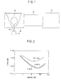
- Figure 1 is a block diagram showing a general electrodeless lamp.
- a general electrodeless lamp comprises: a microwave generator 10 for generating microwave or radio frequency energy by being applied an outer electric power (not shown); a waveguide 20 connected to the microwave generator 10 for transmitting the microwave generated in the microwave generator 10; a resonating device 30 having an inner space for resonating the microwave transmitted through the waveguide 20 by making an outer wall thereof as a mesh structure; and a bulb 40 installed in the inner space of the resonating device 30 for emitting light as being excited by the microwave.
- the bulb 40 comprises an envelope which is able to permeate the light, and filled material for forming plasma by the microwave to emit the light filled in the envelope with buffer gas comprising argon (Ar), etc..
- the bulb 40 is coupled to a rotational shaft 52 extended from a rotating motor 51 which is positioned on an outer side of the resonating device 30 so as to be rotated for cooling.
- the microwave generator 10 When the electric source is applied, the microwave generator 10 generates microwave, and the microwave transmitted to the resonating device 30 through the waveguide 20 excites the filled material filled in the bulb 40 to form the plasma, and thereby the light is emitted.
- the bulb 40 At that time, the bulb 40 generates a lot of heat as forming the plasma therein, and the bulb 40 is cooled down by being rotated according to the operation of the rotating motor 51.
- the electrodeless lamp comes to have different characteristics according to the filled material and the buffer gas which are filled in the bulb 40. Especially, a light emitting efficiency, an energy efficiency, initial lighting, re-lighting time, and stability are differentiated according to the buffer gas filled inside the bulb 40.
- the general electrodeless lamp can be re-lighted only after a predetermined time (tens of seconds ⁇ few minutes) has passed when the light is put out. It is caused by that a pressure of neutral gas in the bulb is too high, and therefore sufficient mean free path of electron having the energy needed to discharge the plasma can not be ensured.
- a first component which is a participle component emitting the light when the high frequency energy is excited, a second component selected from a group of Xe and Kr and assigned to have a predetermined partial pressure, and a third component selected from a group of Ar, Ne, and He, and assigned to have a predetermined partial pressure are included in the bulb of the electrodeless lamp, and the partial pressure of the second component is larger than that of the third component.
- the pressure of second component is in a range of 50 ⁇ 200 torr
- the pressure of third component is in a range of 5 ⁇ 20 torr.
- the Xe that is, the second component has relatively higher light emitting efficiency in the most preferred embodiment.
- the initial lighting or the re-lighting is difficult, and therefore, a large electric field, that is, high frequency energy is needed in initial lighting, and the re-lighting time may be increased or the re-lighting may not be made.
- an object of the present invention is to provide a bulb for an electrodeless lamp by which re-lighting after putting out light can be made easily, and re-lighting time can be reduced.
- a bulb for an electrodeless lamp comprising:
- a bulb for an electrodeless lamp comprising: an envelope through which the light can be permeated; a filled material filled in the envelope for emitting the light as being excited by high frequency energy; and buffer gas, wherein the buffer gas comprises first buffer gas selected from a group including Ne and Xe, and second buffer gas including Ar having a partial pressure less than 1% of the partial pressure of the first buffer gas in order to reduce a discharging voltage and lighting time.
- the buffer gas comprises first buffer gas selected from a group including Ne and Xe, and second buffer gas including Ar having a partial pressure less than 1% of the partial pressure of the first buffer gas in order to reduce a discharging voltage and lighting time.
- an electrodeless lamp comprising: a microwave generation unit for generating microwave; a waveguide unit coupled to the microwave generation unit for transmitting the microwave generated from the microwave generation unit; a resonance unit connected to the waveguide unit for resonating the microwave which is transmitted through the waveguide; and a bulb unit disposed in the resonance unit for emitting light as being excited by the microwave, wherein the bulb unit comprises: an envelope through which the light can be permeated; a filled material filled in the envelope for emitting the light as being excited by high frequency energy; and buffer gas, comprising first buffer gas, and second buffer gas having a partial pressure less than 1% of the partial pressure of the first buffer gas in order to reduce a discharging voltage and lighting time.
- the envelope is formed to be a spherical shape or to be a cylindrical shape, and is made of a material having high light transmittance and low dielectric loss such as quartz generally.
- the filled material is a material which is able to emit the light required by the electrodeless lamp, and metal halide and the like can be used as the filled material.
- the filled material is existed as solid status in a room temperature, and existed as gas state having high vapor pressure at a predetermined temperature.
- Ne is used as the first buffer gas
- Kr and Xe also can be used as the first buffer gas.
- a partial pressure of the first buffer gas is maintained to be 200 torr or less at the room temperature (about 25°C).
- the second buffer gas is a different gas from the first buffer gas.
- Ar can be used as the second buffer gas, and He, Ne, Kr, or Xe also can be used as the second buffer gas.
- the partial pressure of the second buffer gas is maintained to be lower than 1% of the partial pressure of the first buffer gas, and it is desirable that the partial pressure of the second buffer gas is maintained around 1 % of the partial pressure of the first buffer gas.
- Another gas besides the first and second buffer gases may be additionally mixed in the buffer gas.
- the microwave is generated by the operation of the microwave generator 10 of the electrodeless lamp shown in Figure 1, and the generated microwave is transmitted to the resonating device 30 through the waveguide 20. And the transmitted microwave excites the filled material and the buffer gas filled in the bulb 40 of the electrodeless lamp, and the plasma is formed to emit the light.
- the voltage higher than a breakdown voltage should be applied. Therefore, when considering the energy efficiency, and the re-lighting time of the electrodeless lamp, the breakdown voltage for the initial starting should be lowered, and therefore, the buffer gas is filled in the bulb 40.
- the electrodeless lamp according to the present invention and buffer gas in which the first buffer gas and the second buffer gas are mixed is filled in the bulb 40, and therefore, the re-lighting of the electrodeless lamp after putting out the lamp can be made easy and the re-lighting time is also reduced by the first and second buffer gases.
- Table 1 is showing excitation voltages and ionization voltages of inert gases to be metastable states.
- He Ne Ar Kr Xe Ionization 24.5 21.5 15.7 14.0 12.1 voltage (V)
- Excitation 19.8 16.6 9.9 6.8 8.3 voltage (V) 20.5 16.7 10.5 1.5 9.4
- Ne is the first buffer gas having the partial pressure lower than 200 torr at the room temperature (about 25°C) and the Ar is the second buffer gas having 1% partial pressure of the first buffer gas
- the starting voltage is greatly lower than that of the buffer gas including Ne only, and the re-lighting can be made stably in a short time.
- the starting for forming the plasma can be made easy by the buffer gas in which Ne gas, that is, the first buffer gas is mixed with a very small amount of the second buffer gas.
- the buffer gas is easily ionized by a small starting voltage, that is, a small electric field, then the gas excites the filled material which emits the light to form the plasma, and therefore, the re-lighting time can be reduced.
- the bulb of the electrodeless lamp is easily started in case that the buffer gas in which Ne and Kr are mixed is filled in the bulb, and the bulb can be started more easily in case that the buffer gas in which Ne and Ar are mixed is filled in the bulb, and therefore, the re-lighting time can be reduced more.
- the buffer gas including the Ne, Ar, Kr, and Xe is optimized to make the re-lighting easy and to reduce the re-lighting time. Therefore, an additional device is not needed, the structure of the lamp is simple and generation of additional cost is prevented.
- the re-lighting after putting out the light can be performed easily and the re-lighting time is reduced, and therefore, the convenience of the user is improved and the reliability of electrodeless lamp is also improved.
Landscapes
- Physics & Mathematics (AREA)
- Engineering & Computer Science (AREA)
- Plasma & Fusion (AREA)
- Electromagnetism (AREA)
- Non-Portable Lighting Devices Or Systems Thereof (AREA)
- Circuit Arrangements For Discharge Lamps (AREA)
- Discharge Lamps And Accessories Thereof (AREA)
Abstract
Description
| He | Ne | Ar | Kr | Xe | |
| Ionization | 24.5 | 21.5 | 15.7 | 14.0 | 12.1 |
| voltage (V) | |||||
| Excitation | 19.8 | 16.6 | 9.9 | 6.8 | 8.3 |
| voltage (V) | 20.5 | 16.7 | 10.5 | 1.5 | 9.4 |
Claims (8)
- A bulb for an electrodeless lamp comprising:an envelope through which the light can be permeated;a filled material filled in the envelope for emitting the light as being excited by high frequency energy; andbuffer gas, wherein the buffer gas comprises first buffer gas, and second buffer gas having a partial pressure less than 1% of the partial pressure of the first buffer gas in order to reduce a discharging voltage and lighting time.
- The bulb of claim 1, wherein the first buffer gas and the second buffer gas are selected respectively from a group including Ne, Ar, Kr, and Xe.
- The bulb of claim 1, wherein a partial pressure of the first buffer gas is 200 torr or less.
- A bulb for an electrodeless lamp comprising:an envelope through which the light can be permeated;a filled material filled in the envelope for emitting the light as being excited by high frequency energy; andbuffer gas, wherein the buffer gas comprises first buffer gas selected from a group including Ne and Xe, and second buffer gas including Ar having a partial pressure less than 1% of the partial pressure of the first buffer gas in order to reduce a discharging voltage and lighting time.
- The bulb of claim 4, wherein a partial pressure of the first buffer gas is 200 torr or less.
- An electrodeless lamp comprising:wherein the bulb unit comprises: an envelope through which the light can be permeated; a filled material filled in the envelope for emitting the light as being excited by high frequency energy; and buffer gas, comprising first buffer gas, and second buffer gas having a partial pressure less than 1% of the partial pressure of the first buffer gas in order to reduce a discharging voltage and lighting time.a microwave generation unit for generating microwave;a waveguide unit coupled to the microwave generation unit for transmitting the microwave generated from the microwave generation unit;a resonance unit connected to the waveguide unit for resonating the microwave which is transmitted through the waveguide; anda bulb unit disposed in the resonance unit for emitting light as being excited by the microwave,
- The lamp of claim 6, wherein the first buffer gas and second buffer gas are selected respectively from a group including Ne, Ar, Kr, and Xe.
- The lamp of claim 6, wherein a partial pressure of the first buffer gas is 200 torr or less.
Applications Claiming Priority (2)
| Application Number | Priority Date | Filing Date | Title |
|---|---|---|---|
| KR2002019534 | 2002-04-10 | ||
| KR10-2002-0019534A KR100459448B1 (en) | 2002-04-10 | 2002-04-10 | Electrodeless lamp for plasma lighting system |
Publications (2)
| Publication Number | Publication Date |
|---|---|
| EP1353359A2 true EP1353359A2 (en) | 2003-10-15 |
| EP1353359A3 EP1353359A3 (en) | 2004-10-13 |
Family
ID=28450134
Family Applications (1)
| Application Number | Title | Priority Date | Filing Date |
|---|---|---|---|
| EP02016900A Withdrawn EP1353359A3 (en) | 2002-04-10 | 2002-07-31 | Lamp bulb and electrodeless lamp therewith |
Country Status (5)
| Country | Link |
|---|---|
| US (1) | US6803724B2 (en) |
| EP (1) | EP1353359A3 (en) |
| JP (1) | JP2003308808A (en) |
| KR (1) | KR100459448B1 (en) |
| CN (1) | CN1450590A (en) |
Families Citing this family (6)
| Publication number | Priority date | Publication date | Assignee | Title |
|---|---|---|---|---|
| KR100724456B1 (en) * | 2005-06-10 | 2007-06-04 | 엘지전자 주식회사 | Electrodeless bulb and electrodeless lighting device using the same |
| DE102005035191A1 (en) * | 2005-07-27 | 2007-02-01 | Patent-Treuhand-Gesellschaft für elektrische Glühlampen mbH | Low-pressure gas discharge lamp with new gas filling |
| US20100156295A1 (en) * | 2006-10-31 | 2010-06-24 | Kyung-Hoon Park | Electrodeless bulb, and electrodeless lighting system having the same |
| KR101039570B1 (en) | 2009-03-04 | 2011-06-09 | (주)이텍 | Electric lamp assembly |
| CN101859681B (en) * | 2009-04-10 | 2012-07-04 | 许树良 | Inflation formula of high-frequency electrodeless lamp |
| CN106683974A (en) * | 2015-11-11 | 2017-05-17 | 迅驰车业江苏有限公司 | Automobile xenon headlamp |
Family Cites Families (12)
| Publication number | Priority date | Publication date | Assignee | Title |
|---|---|---|---|---|
| US3814971A (en) * | 1973-03-01 | 1974-06-04 | Gen Electric | Fill gas mixture for glow lamps |
| JPS5719952A (en) * | 1980-07-09 | 1982-02-02 | Mitsubishi Electric Corp | Low pressure gas discharge lamp for generating near infrared radiation |
| JPS5825071A (en) * | 1981-08-05 | 1983-02-15 | Mitsubishi Electric Corp | Electrodeless discharge lamp for microwave discharge |
| US4972120A (en) * | 1989-05-08 | 1990-11-20 | General Electric Company | High efficacy electrodeless high intensity discharge lamp |
| EP0457242B1 (en) * | 1990-05-15 | 1995-08-30 | Osram Sylvania Inc. | Electrodeless HID lamp with microwave power coupler |
| US5834895A (en) * | 1990-10-25 | 1998-11-10 | Fusion Lighting, Inc. | Visible lamp including selenium |
| EP0521553B1 (en) * | 1991-07-01 | 1996-04-24 | Koninklijke Philips Electronics N.V. | High-pressure glow discharge lamp |
| CA2111426A1 (en) * | 1992-12-18 | 1994-06-19 | Alfred E. Feuersanger | Electrodeless lamp bulb |
| JPH07134948A (en) * | 1993-11-10 | 1995-05-23 | Oki Electric Ind Co Ltd | Gas discharge light emitting device |
| EP1003636A1 (en) | 1997-08-13 | 2000-05-31 | Fusion Lighting, Inc. | Direct rotary screen printing on cylindrical articles |
| US6522084B1 (en) * | 1999-10-18 | 2003-02-18 | Matsushita Electric Industrial Co., Ltd. | Electrodeless discharge lamp operating apparatus |
| KR100348610B1 (en) * | 2000-01-19 | 2002-08-13 | 엘지전자주식회사 | Metal halogen electrodeless illumination lamps |
-
2002
- 2002-04-10 KR KR10-2002-0019534A patent/KR100459448B1/en not_active Expired - Fee Related
- 2002-07-31 EP EP02016900A patent/EP1353359A3/en not_active Withdrawn
- 2002-08-07 US US10/213,079 patent/US6803724B2/en not_active Expired - Lifetime
- 2002-08-22 JP JP2002242080A patent/JP2003308808A/en active Pending
- 2002-08-23 CN CN02130164A patent/CN1450590A/en active Pending
Also Published As
| Publication number | Publication date |
|---|---|
| US20030193290A1 (en) | 2003-10-16 |
| CN1450590A (en) | 2003-10-22 |
| KR20030080747A (en) | 2003-10-17 |
| EP1353359A3 (en) | 2004-10-13 |
| KR100459448B1 (en) | 2004-12-03 |
| US6803724B2 (en) | 2004-10-12 |
| JP2003308808A (en) | 2003-10-31 |
Similar Documents
| Publication | Publication Date | Title |
|---|---|---|
| US6522084B1 (en) | Electrodeless discharge lamp operating apparatus | |
| US4672267A (en) | High intensity discharge device containing oxytrihalides | |
| Uhrlandt et al. | Low-pressure mercury-free plasma light sources: experimental and theoretical perspectives | |
| CN101217098B (en) | A light source of UHF electrodeless discharge lamp | |
| US6803724B2 (en) | Electrodeless lamp and lamp bulb therefor | |
| US4427924A (en) | Enhanced electrodeless light source | |
| US6084348A (en) | Lamp having specific fill providing reduced restrike time | |
| US7253555B2 (en) | Electrodeless lamp system and bulb thereof | |
| US20120187871A1 (en) | Low-pressure discharge lamp | |
| US5331254A (en) | Starting circuit for an electrodeless high intensity discharge lamp employing a visible light radiator | |
| EP2104131A1 (en) | Electrodeless discharge lamp and illumination device equipped with same | |
| CN100405528C (en) | Discharge light source excited by electron beam | |
| US6121730A (en) | Metal hydrides lamp and fill for the same | |
| US6670759B1 (en) | Electrodeless discharge lamp | |
| Golovitskiı̆ | Low-pressure inductive rf discharge in a rare gas-halogen mixture for economical mercury-free luminescence light sources. | |
| US5760547A (en) | Multiple-discharge electrodeless fluorescent lamp | |
| WO2003061353A1 (en) | Microwave-powered ultraviolet rotating lamp, and process of use thereof | |
| JP3167217B2 (en) | Electrodeless discharge lamp lighting device | |
| US20130147349A1 (en) | Integral starter for electrodeless lamp | |
| JP3178259B2 (en) | Electrodeless discharge lamp | |
| EP1414058A2 (en) | Electrodeless lamp system and bulb thereof | |
| KR100898525B1 (en) | Electrodeless discharge lamp module | |
| Uhrlandt et al. | Low-pressure mercury-free plasma light sources: theoretical and experimental perspectives | |
| JP2000348889A (en) | High frequency energy supply device and high frequency electrodeless discharge device | |
| Lapatovich et al. | High intensity discharge device containing oxytrihalides |
Legal Events
| Date | Code | Title | Description |
|---|---|---|---|
| PUAI | Public reference made under article 153(3) epc to a published international application that has entered the european phase |
Free format text: ORIGINAL CODE: 0009012 |
|
| AK | Designated contracting states |
Kind code of ref document: A2 Designated state(s): AT BE BG CH CY CZ DE DK EE ES FI FR GB GR IE IT LI LU MC NL PT SE SK TR |
|
| AX | Request for extension of the european patent |
Extension state: AL LT LV MK RO SI |
|
| PUAL | Search report despatched |
Free format text: ORIGINAL CODE: 0009013 |
|
| AK | Designated contracting states |
Kind code of ref document: A3 Designated state(s): AT BE BG CH CY CZ DE DK EE ES FI FR GB GR IE IT LI LU MC NL PT SE SK TR |
|
| AX | Request for extension of the european patent |
Extension state: AL LT LV MK RO SI |
|
| 17P | Request for examination filed |
Effective date: 20050204 |
|
| 17Q | First examination report despatched |
Effective date: 20050301 |
|
| AKX | Designation fees paid |
Designated state(s): DE FR GB IT SE |
|
| GRAP | Despatch of communication of intention to grant a patent |
Free format text: ORIGINAL CODE: EPIDOSNIGR1 |
|
| RIC1 | Information provided on ipc code assigned before grant |
Ipc: H01J 61/16 20060101ALI20111121BHEP Ipc: H01J 65/04 20060101ALI20111121BHEP Ipc: H01J 61/12 20060101AFI20111121BHEP |
|
| STAA | Information on the status of an ep patent application or granted ep patent |
Free format text: STATUS: THE APPLICATION IS DEEMED TO BE WITHDRAWN |
|
| 18D | Application deemed to be withdrawn |
Effective date: 20120201 |