EP1353354A1 - Plasma display device - Google Patents
Plasma display device Download PDFInfo
- Publication number
- EP1353354A1 EP1353354A1 EP02770248A EP02770248A EP1353354A1 EP 1353354 A1 EP1353354 A1 EP 1353354A1 EP 02770248 A EP02770248 A EP 02770248A EP 02770248 A EP02770248 A EP 02770248A EP 1353354 A1 EP1353354 A1 EP 1353354A1
- Authority
- EP
- European Patent Office
- Prior art keywords
- phosphor
- hydrate
- blue
- luminance
- hydrothermal synthesis
- Prior art date
- Legal status (The legal status is an assumption and is not a legal conclusion. Google has not performed a legal analysis and makes no representation as to the accuracy of the status listed.)
- Withdrawn
Links
Images



Classifications
-
- H—ELECTRICITY
- H01—ELECTRIC ELEMENTS
- H01J—ELECTRIC DISCHARGE TUBES OR DISCHARGE LAMPS
- H01J9/00—Apparatus or processes specially adapted for the manufacture, installation, removal, maintenance of electric discharge tubes, discharge lamps, or parts thereof; Recovery of material from discharge tubes or lamps
- H01J9/20—Manufacture of screens on or from which an image or pattern is formed, picked up, converted or stored; Applying coatings to the vessel
- H01J9/22—Applying luminescent coatings
- H01J9/221—Applying luminescent coatings in continuous layers
- H01J9/223—Applying luminescent coatings in continuous layers by uniformly dispersing of liquid
-
- C—CHEMISTRY; METALLURGY
- C09—DYES; PAINTS; POLISHES; NATURAL RESINS; ADHESIVES; COMPOSITIONS NOT OTHERWISE PROVIDED FOR; APPLICATIONS OF MATERIALS NOT OTHERWISE PROVIDED FOR
- C09K—MATERIALS FOR MISCELLANEOUS APPLICATIONS, NOT PROVIDED FOR ELSEWHERE
- C09K11/00—Luminescent materials, e.g. electroluminescent or chemiluminescent
- C09K11/08—Luminescent materials, e.g. electroluminescent or chemiluminescent containing inorganic luminescent materials
-
- C—CHEMISTRY; METALLURGY
- C09—DYES; PAINTS; POLISHES; NATURAL RESINS; ADHESIVES; COMPOSITIONS NOT OTHERWISE PROVIDED FOR; APPLICATIONS OF MATERIALS NOT OTHERWISE PROVIDED FOR
- C09K—MATERIALS FOR MISCELLANEOUS APPLICATIONS, NOT PROVIDED FOR ELSEWHERE
- C09K11/00—Luminescent materials, e.g. electroluminescent or chemiluminescent
- C09K11/08—Luminescent materials, e.g. electroluminescent or chemiluminescent containing inorganic luminescent materials
- C09K11/59—Luminescent materials, e.g. electroluminescent or chemiluminescent containing inorganic luminescent materials containing silicon
-
- C—CHEMISTRY; METALLURGY
- C09—DYES; PAINTS; POLISHES; NATURAL RESINS; ADHESIVES; COMPOSITIONS NOT OTHERWISE PROVIDED FOR; APPLICATIONS OF MATERIALS NOT OTHERWISE PROVIDED FOR
- C09K—MATERIALS FOR MISCELLANEOUS APPLICATIONS, NOT PROVIDED FOR ELSEWHERE
- C09K11/00—Luminescent materials, e.g. electroluminescent or chemiluminescent
- C09K11/08—Luminescent materials, e.g. electroluminescent or chemiluminescent containing inorganic luminescent materials
- C09K11/77—Luminescent materials, e.g. electroluminescent or chemiluminescent containing inorganic luminescent materials containing rare earth metals
- C09K11/7728—Luminescent materials, e.g. electroluminescent or chemiluminescent containing inorganic luminescent materials containing rare earth metals containing europium
- C09K11/77342—Silicates
-
- H—ELECTRICITY
- H01—ELECTRIC ELEMENTS
- H01J—ELECTRIC DISCHARGE TUBES OR DISCHARGE LAMPS
- H01J11/00—Gas-filled discharge tubes with alternating current induction of the discharge, e.g. alternating current plasma display panels [AC-PDP]; Gas-filled discharge tubes without any main electrode inside the vessel; Gas-filled discharge tubes with at least one main electrode outside the vessel
- H01J11/20—Constructional details
- H01J11/34—Vessels, containers or parts thereof, e.g. substrates
- H01J11/42—Fluorescent layers
-
- H—ELECTRICITY
- H01—ELECTRIC ELEMENTS
- H01J—ELECTRIC DISCHARGE TUBES OR DISCHARGE LAMPS
- H01J2211/00—Plasma display panels with alternate current induction of the discharge, e.g. AC-PDPs
- H01J2211/20—Constructional details
- H01J2211/34—Vessels, containers or parts thereof, e.g. substrates
- H01J2211/42—Fluorescent layers
Definitions
- the present invention relates to a plasma display device for displaying image on a television or other equipment.
- a plasma display device having a plasma display panel (hereinafter referred to as a PDP) has recently received considerable attention as a color display device with large sized screen but lightweight body due to its low-profile structure.
- a PDP displays image in full color by performing an additive color process on red, green, and blue - known as the three primary colors.
- the PDP has phosphor layers that are respectively prepared for emitting red (R), green (G), and blue (B) of the three fundamental colors.
- a phosphor layer is formed of phosphor particles. The phosphor particles are excited by ultraviolet rays generated in a discharge cell in the PDP, so that visible lights of red, green, and blue are produced.
- each phosphor is manufactured through solid phase reaction; after mixed predetermined material, it is baked at high temperature beyond 1000 °C (for example, see Phosphor Handbook, pp 219 and 225, Ohmsha). Because the baking process sinters the phosphor particles, they should be crushed to a proper size before using: an average particle diameter of 2-5 ⁇ m for the red, and the green phosphors, 3-10 ⁇ m for the blue phosphor.
- the prior-art phosphors above have a problem - particularly in the blue phosphor formed of BaMgAl 10 O 17 :Eu, phosphor luminance decreases in the heating step of the phosphor layer-forming process or under panel operation.
- Employing the crystal structure of CaMgSi 2 O 6 :Eu system as the blue phosphor can slightly improve in the phosphor luminance in the heating step of the phosphor layer-forming process or in panel operation; however, the manufacturing method and the crystal structure by the conventional solid phase reaction has been facing the problem of low luminance - especially under panel operation, serious degradation in luminance occurs.
- the inconvenience comes from the fact that the blue emitting phosphor with the crystal structure of CaMgSi 2 O 6 :Eu is easy to undergo sintering, due to its low melting point, in the solid phase reaction. Therefore, there is no way, without crushing, to obtain a blue phosphor particle having the diameter less than 8 ⁇ m.
- the crystal of CaMgSi 2 O 6 :Eu as the phosphor should preferably be sintered at temperatures around 1400 °C; however, such a high temperature accelerates particle growth, allowing each particle to have a particle diameter of several ten ⁇ m.
- the present invention addresses the inconvenience above. It is therefore the object to obtain the blue emitting phosphor with high luminance. Also, it is another object to provide a panel that can minimize degradation in luminance.
- the plasma display device of the present invention has a structural improved blue-emitting phosphor having the average particle diameter ranging from 0.1 to 3.0 ⁇ m.
- the phosphor for blue emission has a structure of MeMgSi 2 O 6 :Eu or Me 3 MgSi 2 O 8 :Eu (where, Me is a mixture of at least one of Ca, Sr, and Ba) produced with a precursor that is obtained by any one of methods: an aqueous solution reaction synthesis method, a spray synthesis method, a hydrothermal synthesis method, and a hydrolysis method.
- Fig. 1 is a schematic plan view of a plasma display panel (PDP), with a front glass substrate removed, in accordance with an embodiment of the present invention.
- Fig. 2 is a perspective view of the PDP, showing a part of an image display area in section.
- the number of display electrodes, display scan electrodes, and address electrodes is reduced for sake of clarity..
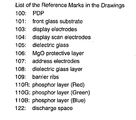
- PDP 100 contains front glass substrate 101 (not shown), rear glass substrate 102, N display electrodes 103, N display scan electrodes 104 (where a parenthesized N indicates the Nth electrode), M address electrode 107 (where a parenthesized M indicates the Mth electrode), and hermetic seal layer 121.
- the PDP has an electrode matrix having a three-electrode structure made of respective electrodes 103, 104, and 107. Cells are formed at the respective intersections of display scan electrodes 104 and address electrodes 107.
- Reference numeral 123 indicates an image display area.
- PDP 100 has, as shown in Fig. 2, front glass substrate 101, and rear glass substrate 102 facing to substrate 101.
- the two substrates form discharge space 122 therebetween, which is filled with a discharge gas.
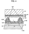
- disposed on a principle surface of rear glass substrate 102 are address electrodes 107, dielectric glass layer 108, barrier ribs 109, and phosphor layers 110(R, G, B).
- Such structured PDP is connected to a driver circuit to form a plasma display device.
- driver circuit 150 When an image is displayed on the plasma display device, first, display driver circuit 153, display scan driver circuit 154, and address driver circuit 155 ⁇ the three circuits form driver circuit 150 - are connected to PDP 100, as shown in Fig. 3. Next, according to the control of controller 152, a voltage is applied across display scan electrode 104 and address electrode 107 of a cell to be lit for address discharge therebetween. Then, a pulse voltage is applied across display electrode 103 and display scan electrode 104 for sustain discharge. The sustain discharge generates ultraviolet light in the cell. The phosphor layers excited by the ultraviolet light emit light, thereby lighting the cell. In this way, combination of lit and unlit cells of the respective colors produces image on the display.
- N display electrodes 103 and N display scan electrodes 104 are arranged on front glass substrate 101 alternately, parallel to each other, like stripes. (In Fig. 2, only two of respective electrodes are shown for simplicity.) Thereafter, the electrodes are covered with dielectric glass layer 105, and further over which, MgO protective layer 106 is formed.
- Display electrodes 103 and display scan electrodes 104 are made of silver. These electrodes are formed by applying a silver paste for electrodes by screen printing and then baking the paste.
- Dielectric glass layer 105 is formed by applying a paste containing lead glass material by screen printing, and baking the paste at a predetermined temperature for a predetermined period of time (e.g. at 560 °C for 20 min.) to obtain a desired thickness (approx. 20 ⁇ m).
- a paste containing lead glass material a mixture of PbO (70 wt%), B 2 O 3 (15 wt%), SiO 2 (10 wt%), Al 2 O 3 (5 wt%) and an organic binder ( ⁇ -terpineol containing 10% of ethyl cellulose dissolved therein) is often used.
- the aforementioned organic binder contains a resin dissolved in an organic solvent.
- Acrylic resin can be used as a resin other than the ethyl cellulose, and n-butylcarbitol as an organic solvent. Further, a dispersant - for, example, glyceryl trileate - can be mixed into such an organic binder.
- MgO protective layer 106 is made of magnesium oxide (MgO).
- the layer is formed into a predetermined thickness (approx. 0.5 ⁇ m) by sputtering or chemical vapor deposition (CVD) method.
- M address electrodes 107 are formed in lines on rear glass substrate 102 by screen printing a silver paste and then baking the paste.
- dielectric glass layer 108 is formed by applying a paste containing lead glass material to the address electrodes by a screen printing.
- barrier ribs 109 are formed by repeatedly applying the same paste containing lead glass material to the dielectric glass layer at a predetermined pitch by screen printing and thereafter baking the paste. These barrier ribs 109 divide, in the direction of the lines, discharge space 122 into respective cells (i.e., unit emission area).
- Fig. 4 is a partially sectional view of PDP 100. As shown in Fig. 4, interval dimension W between barrier ribs 109 is determined to a value ranging from approx. 130 to 240 ⁇ m, according to a high definition television (HD-TV) screen having a diagonal size ranging from 32 to 50 in.
- HDMI high definition television
- Red (R) and green (G) phosphor particles are prepared by a hydrothermal synthesis method, and blue (B) phosphor particles are prepared by a hydrothermal synthesis method, atomization synthesis method, or hydrolysis method.
- Paste-like phosphor ink made of red (R), green (G), or blue (B) phosphor particles and an organic binder is applied to grooves between barrier ribs 109, and baked at temperatures ranging from 400 to 590 °C to burn out the organic binder.
- phosphor layers 110 - in which phosphor particles of corresponding colors are bound with each other - are formed.
- thickness L in the direction of lamination of phosphor layers 110 on address electrode 107 is approx. 8 to 25 times the average diameter of phosphor particles of each color. That is, in order to constantly achieve a certain luminance (emission efficiency) when a phosphor layer is irradiated with an amount of ultraviolet light, the phosphor layer needs to absorb ultraviolet light generated in the discharged space, not allowing to pass therethrough. For this purpose, it is desirable that the phosphor layer has a thickness formed of at least eight layered-, preferable, approx. 20 layered-phosphor particles. Having a thickness beyond 20-layered lamination almost "saturates" emission efficiency - this is because sufficiently large discharge space 122 cannot be ensured due to the thickened layer.
- Phosphor particles having preferably small diameters and spherical shapes like those obtained by hydrothermal synthesis, atomization synthesis, hydrolysis methods, have a packing factor of the phosphor layer and a total surface area of the phosphor particles larger than those of phosphor particles having non-spherical shapes, even when the number of laminated layers are the same.
- phosphor particles having spherical shapes increase the surface area contributing to actual light emission of the phosphor layer, thereby enhancing the emission efficiency.
- the synthesis method of phosphor layers 110 and the phosphor particles employed for the phosphor layers will be described later.
- discharge space 122 is once evacuated to a high vacuum (e.g. 1.1 ⁇ 10 -4 Pa) and filled with a discharge gas, namely, He-Xe or Ne-Xe inert gas, at a predetermined pressure, to complete PDP 100.
- a high vacuum e.g. 1.1 ⁇ 10 -4 Pa
- a discharge gas namely, He-Xe or Ne-Xe inert gas
- Fig. 5 is a schematic diagram showing the structure of an ink dispenser used in forming phosphor layers 110.
- ink dispenser 200 includes server 210, pressure pump 220, and header 230.
- Phosphor ink is pressurized by pressure pump 220 and supplied from server 210, which stores the phosphor ink, to header 230.
- Header 230 contains ink chamber 230a and nozzle 240.
- the phosphor ink, which was fed to ink chamber 230a with application of pressure, is continuously ejected from nozzle 240. It is desirable that bore diameter D of nozzle 240 is sized at least 30 ⁇ m to prevent clogging of the nozzle.
- bore diameter D is equal to or smaller than interval W between barrier ribs 109 (approx. 130 to 200 ⁇ m) to properly apply the ink to the groove between the barrier ribs.
- bore diameter D is usually determined to 30 to 130 ⁇ m.
- Header 230 is structured to be driven lineally by a header scanning mechanism (not shown). Continuously ejecting phosphor ink 250 from nozzle 240 while scanning header 230 allows phosphor ink to be uniformly applied to the grooves between barrier ribs 109 on rear glass substrate 102. Viscosity of the phosphor ink is kept within the range of 1500 to 30000 centipoises (CP) at a temperature of 25 °C.
- CP centipoises
- This server 210 also has a mixer (not shown). Mixing prevents precipitation of particles in phosphor ink.
- Header 230 is integrally formed with ink chamber 230a and nozzle 240 by performing machining and electric discharge machining on a metallic material.
- Forming phosphor layers is not limited to the aforementioned method; other various kinds of methods, such as photolithography, screen printing, and a method of disposing a film including phosphor particles mixed therein, can be employed.
- the phosphor ink is prepared by mixing phosphor particles of each color, a binder, and a solvent so that the mixture has a viscosity ranging 1,500 to 30,000 centipoises (CP).
- CP centipoises
- a surface active agent, silica, a dispersant in amount of 0.1 to 5 wt% can also be added, as required.
- red phosphor included in this phosphor ink a compound represented by (Y, Gd) 1-x BO 3 :Eu x or Y 2-x O 3 :Eu x is used.
- the element Eu substitutes for a part of the element Y constituting the matrix of the compounds.
- the substitution value X of the element Eu with respect to the element Y is 0.05 ⁇ X ⁇ 0.20. Having X larger than 0.20 invites serious degradation in luminance in spite of achieving a high luminance. For the reason, such a red phosphor is unlikely to be practical.
- having X smaller than 0.05 lowers the composition ratio of Eu mainly emitting light, accordingly decreasing the luminance. The phosphor with decreased luminance can no longer serve as a phosphor.
- a compound represented by Ba 1-x Al 12 O 19 :Mn x or Zn 2 . x SiO 4 :Mn x is used.
- Ba 1-x Al 12 O 19 :Mn x is a compound in which the element Mn substitutes for a part of the element Ba constituting the matrix of the compound.
- Zn 2-x SiO 4 :Mn x is a compound in which the element Mn substitutes for a part of the element Zn constituting the matrix of the compound.
- the substitution value X of the element Mn with respect to the element Ba or Zn is 0.01 ⁇ X ⁇ 0.10.
- Me 1-x MgSi 2 O 6 :Eu x or Me 3(1-x) MgSi 2 O 8 :Eu x - where, Me is a mixture of at least one of Ca, Sr, and Ba - is used.
- Me 1-x MgSi 2 O 6 :Eu x and Me 3(1-x) MgSi 2 O 8 :Eu x are compounds in which the element Eu substitutes for a part of the element Me(Ca, Sr, Ba) constituting the matrix of the compounds.
- the substitution value X of the element Eu with respect to the element Me should preferably be 0.03 ⁇ X ⁇ 0.2.
- the each phosphor described above is a phosphor (with no grinding process), which is manufactured with a precursor obtained through an aqueous solution reaction method, hydrothermal synthesis method, atomization baking method, or hydrolysis method. These methods of manufacturing phosphors will be explained later.
- Ethyl cellulose or acrylic resin can be used as a binder included in phosphor ink (in an amount of 0.1 to 10 wt% of the ink).
- ⁇ -terpineol or n-butylcarbitol can be used as a solvent.
- Polymers, such as PMA and PVA, can also be used as a binder.
- organic solvent such as diethyleneglycol and methyl ether, can also be used.
- a precursor for a phosphor is prepared in an aqueous solution.
- the embodiment employs a hydrothermal synthesis method, atomization synthesis method, hydrolysis method to manufacture a phosphor particle.
- a hydrothermal synthesis method atomization synthesis method
- hydrolysis method to manufacture a phosphor particle.
- the aforementioned method is a synthesis and crystal growth method, which provides spherical phosphor particles.
- Ca 1-x MgSi 2 O 6 :Eu x which is known as a blue phosphor.
- This mixture is dissolved in an aqueous medium to prepare a mixed solution.
- Ionexchange water or pure water is preferably used for the aqueous medium by virtue of its containing no impurities; however, an aqueous medium containing non-aqueous solvent (e.g. methanol and ethanol) can also be used.
- an alkaline (basic) solution such as potassium hydrate
- a hydrate i.e., a precursor
- the hydrate is hydro-thermally synthesized in a high pressure vessel, using equipment capable of heating and pressurizing at the same time, such as an autoclave, at specified temperatures (100 to 300 °C) under specified pressures (0.2 to 10 MPa).
- an aluminum powder or a graphite powder is used as a reducer for the blue phosphor.
- the hydrothermal synthesis is thus carried out for 12 to 20 hours to obtain a spherical precursor.
- a spray synthesis method can be used.
- the hydrate mixed solution is directly fed from the pressure nozzle; the solution is ultrasonically sprayed into a furnace heated at temperatures ranging from 1000 to 1500 °C to obtain the spherical precursor.
- the obtained precursor powder is baked in a reducing atmosphere containing 5% of hydrogen and 95% of nitrogen, for example, at a specified temperature for a specified period of time (e.g. at 800 to 1400 °C for two hours). Thereafter, the baked powders are classified to provide a desired blue phosphor, Ca 1-x MgSi 2 O 6 :Eu x .
- the phosphor particles obtained by the hydrothermal synthesis or the atomization synthesis have a spherical shape and an average particle diameter ranging from 0.05 to 3.0 ⁇ m, which is smaller than that of particles fabricated by the conventional solid phase reaction method.
- the wording "spherical shape" used here is defined so that the aspect ratios (minor axis diameter/major axis diameter) of most of the phosphor particles range, for example, from 0.9 to 1.0; however, not all the phosphor particles need to be within the range.
- the phosphor differs from aforementioned Ca 1-x MgSi 2 O 6 :Eu x in only that the element Sr substitutes for a part of the element Ca of Ca 1-x MgSi 2 O 6 :Eu x (where, the ratio of Sr to Ca is 0.1-1 to 0-1).
- the materials used are described hereinafter.
- the hydrate After baked in the air at temperatures 800 to 1,450 °C, the hydrate is further baked at 1000 to 1400 °C in a reducing atmosphere, and then the particles are classified.
- the aqueous solution reaction method can provide a desired blue phosphor.
- the materials i.e., calcium alkoxide [Ca(O•R) 2 ], barium alkoxide [Ba(O•R) 2 ], where, the ratio of Ca to Ba is 0-1 to 1-1, silicon alkoxide [Si(O•R) 4 ], europium alkoxide [Eu(O•R) 3 ] - where, R belongs to an alkyl group, are mixed so as to have the molar ratio of 1-X:1:2:X (0.03 ⁇ X ⁇ 0.2).
- the mixture is hydrolyzed by the addition of water or alcohol to obtain a spherical precursor.
- the precursor is baked at temperatures ranging from 1000 to 1400 °C.
- the obtained particles are baked in a reducing atmosphere, for example, containing 5% of hydrogen and 95% of nitrogen, at a specified temperature for a specified period of time (e.g. at 1000 to 1400 °C for two hours). Thereafter, using an air classifier, the particles are classified to obtain a blue phosphor. In this way, the hydrolysis method can also provide a blue phosphor.
- a reducing atmosphere for example, containing 5% of hydrogen and 95% of nitrogen
- This mixture is dissolved in an aqueous medium to prepare a mixed solution.
- aqueous medium ion-exchange water or pure water is preferably used by virtue of its containing no impurities; however, an aqueous medium containing non-aqueous solvent (e.g. methanol and ethanol) can also be used.
- non-aqueous solvent e.g. methanol and ethanol
- an alkaline (basic) solution such as potassium hydrate
- a corrosion- and heat-resistant material such as gold and platinum
- the hydrate is hydro-thermally synthesized in a high pressure vessel, using equipment capable of heating and pressurizing at the same time, such as an autoclave, at specified temperatures (100 to 300 °C) under specified pressures (0.2 to 10 MPa).
- an aluminum powder or a graphite powder is used as a reducer for the blue phosphor.
- the hydrothermal synthesis is thus carried out for 12 to 20 hours to obtain a spherical precursor.
- a spray synthesis method can be used.
- the hydrate mixed solution is directly fed from the pressure nozzle; the solution is ultrasonically sprayed into a furnace heated at temperatures ranging from 1000 to 1500 °C to obtain the spherical precursor.
- the obtained precursor powder is baked in a reducing atmosphere containing 5% of hydrogen and 95% of nitrogen, for example, at a specified temperature for a specified period of time (e.g. at 800 to 1400 °C for two hours). Thereafter, the baked powders are classified to provide a desired blue phosphor, Ba 3(1-x )MgSi 2 O 3 :Eu.
- the phosphor particles obtained by the hydrothermal synthesis or the atomization synthesis have a spherical shape and an average particle diameter ranging from 0.05 to 3.0 ⁇ m, which is smaller than that of particles fabricated by the conventional solid phase reaction method.
- the wording "spherical shape" used here is defined so that the aspect ratios (minor axis diameter/major axis diameter) of most of the phosphor particles range, for example, from 0.9 to 1.0; however, not all the phosphor particles need to have the range.
- the phosphor differs from aforementioned Ba 3(1-x) MgSi 2 O 8 :Eu x in only that the element Sr substitutes for a part of the element Ba of Ba 3(1-x) MgSi 2 O 8 :Eu x (where, the ratio of Ba to Sr is 0.1-1 to 0-1).
- the materials used are described hereinafter.
- the aqueous solution reaction method can provide a desired blue phosphor.
- the materials i.e., calcium alkoxide [Ca(O•R) 2 ], barium alkoxide [Ba(O•R) 2 ], where, the ratio of Ca to Ba is 0-1 to 1-1, silicon alkoxide [Si(O•R) 4 ], europium alkoxide [Eu(O•R) 3 ] - where, R belongs to an alkyl group, are mixed so as to have the molar ratio of 3(1-X):1:2:X (0.003 ⁇ X ⁇ 0.2).
- the mixture is hydrolyzed by the addition of water or alcohol to obtain a spherical precursor.
- the precursor is baked at temperatures ranging from 1000 to 1400 °C.
- the obtained particles are further baked in a reducing atmosphere containing, for example, 5% of hydrogen and 95% of nitrogen, at a specified temperature for a specified period of time (e.g. at 1000 to 1400 °C for two hours). Thereafter, using an air classifier, the particles are classified to obtain a blue phosphor. In this way, the hydrolysis method can also provide a blue phosphor.
- a phosphor of Zn 2(1-x) SiO 4 :Mn x is described.
- This mixture is dissolved in ion-exchange water to prepare a mixed solution.
- alkaline solution e.g. ammonia aqueous solution
- a hydrothermal synthesis process put the hydrate and the ion-exchange water into a capsule made of a corrosion- and heat-resistant material, such as gold and platinum. Then, the capsule containing the mixed solution is put into a high-pressure vessel to undergo hydrothermal synthesis.
- the hydrothermal synthesis process goes on for 2 to 10 hours at specified temperatures (100 to 300 °C) under specified pressures (0.2 to 10 MPa), for example, with autoclave pressure being applied.
- the hydro-thermally synthesized particles are dried to obtain a desired phosphor of Zn 2(1-x) SiO 4 :Mn x .
- the phosphor particle obtained by hydrothermal synthesis has a spherical shape and an average particle diameter ranging from approx. 0.1 to 2.0 ⁇ m.
- the phosphor particles are annealed in the air at temperatures ranging from 800 to 1100 °C and then classified. The green phosphor powder is thus obtained.
- a phosphor of Ba 1-x Al 12 O 19 :Mn x a phosphor of Ba 1-x Al 12 O 19 :Mn x .
- This mixture is dissolved in ion-exchange water to prepare a mixed solution.
- a hydrate producing process drop alkaline solution (e.g. ammonia aqueous solution) into the mixed solution to prepare a hydrate.
- drop alkaline solution e.g. ammonia aqueous solution
- a hydrothermal synthesis process put the hydrate and the ion-exchange water into a capsule made of a corrosion- and heat-resistant material, such as gold and platinum.
- the capsule containing the mixed solution is put into a high-pressure vessel to undergo hydrothermal synthesis.
- the hydrothermal synthesis process goes on for 2 to 20 hours at specified temperatures (100 to 300 °C) under specified pressures (0.2 to 10 MPa), for example, with autoclave pressure being applied
- the hydro-thermally synthesized particles are dried to obtain a desired phosphor of Ba 1-x Al 12 O 19 :M nx .
- the phosphor particle obtained by hydrothermal synthesis has a spherical shape and an average particle diameter ranging from approx. 0.1 to 2.0 ⁇ m.
- the phosphor particles are annealed in the air at temperatures ranging from 800 to 1100 °C and then classified. The green phosphor powder is thus obtained.
- a hydrothermal synthesis process put the hydrate and the ion-exchange water into a container made of a corrosion- and heat-resistant material, such as gold and platinum. Then, the container having the mixed solution is put into a high-pressure vessel to undergo hydrothermal synthesis.
- the hydrothermal synthesis takes place for 3 to 12 hours at specified temperatures (100 to 300 °C) under specified pressures (0.2 to 10 MPa), for example, with autoclave pressure being applied.
- the phosphor particle obtained by hydrothermal synthesis has a spherical shape and an average particle diameter ranging from approx. 0.1 to 2.0 ⁇ m. The phosphor is heated for two hours in the air at temperatures ranging from 800 to 1200 °C and then classified. A red phosphor is thus obtained.
- Y 2-x O 3 :Eu x a description of Y 2-x O 3 :Eu x is provided.
- the mixture is dissolved in ion-exchange water to prepare a mixed solution.
- an aqueous base such as ammonia aqueous solution, to the mixed solution to provide a hydrate.
- hydrothermal synthesis process put the hydrate and the ion-exchange water into a container made of a corrosion- and heat-resistant material, such as gold and platinum. Then, the container having the mixed solution is put into a high-pressure vessel to undergo hydrothermal synthesis.
- the hydrothermal synthesis takes place for 3 to 12 hours at specified temperatures (100 to 300 °C) under specified pressures (0.2 to 10 MPa), for example, with the application of autoclave pressure.
- the compound obtained by hydrothermal synthesis is dried to obtain a desired phosphor of Y 2-x O 3 :Eu x .
- the phosphor particles are annealed in the air at temperatures ranging from 800 to 1200 °C and then classified.
- the red phosphor powder is thus obtained.
- the phosphor obtained by the hydrothermal synthesis process has a spherical shape and particle diameters ranging from approx. 0.1 to 2.0 ⁇ m. Such a shape and a size are suitable for forming a phosphor layer that exhibits excellent light emission characteristics.
- the phosphor particles described in (1) through (3) are produced by a hydrothermal synthesis method, atomization synthesis method, or hydrolysis method, using a spherical precursor prepared in an aqueous solution. This is why a particle has a spherical shape and a small average particle diameter (of approx. 0.1 to 2.0 ⁇ m).
- the phosphor obtained through the synthesis method above has no oxygen vacancy on its surface of the particle, whereby not only luminance of the phosphor but also luminance degradation is significantly improved.
- ultraviolet light penetrates not so far from the surface of the phosphor particle: approx. several hundreds nm. That is, emission occurs almost at the surface. Considering the fact, 2.0 ⁇ m or smaller particle diameter increases the surface area of a particle contributing to emission. This allows the phosphor layers to maintain high luminance.
- the phosphor particle produced through the synthesis methods above sustains crystal growth with the spherical shape kept, so that the particle has fewer structural defects including the oxygen vacancy. Accordingly, ultraviolet light absorbed in the oxygen vacancy decreases, on the other hand, excitation at a mainly emitting element easily occurs.
- the spherical shape of the particle contributes to avoid each particle from sticking together in the baking process at high temperatures, whereby the particle can be easily crushed.
- the particle with fewer oxygen vacancy can not only provide high luminance, but also minimize luminance degradation caused by the oxygen vacancy.
- the phosphor of the present invention can have a particle diameter on the order of sub-microns, thereby minimizing inconsistencies in coating when the phosphor is applied.
- a packing factor of the phosphor forming a phosphor layer increases; accordingly, the PDP of the present invention has a higher luminance than that of a conventional one.
- hydro-thermally synthesized phosphor particles are employed for all the phosphor layers, which are responsible for red and green emission.
- An aqueous solution reaction method or atomization synthesis method can provide red-, and green-phosphor layers almost the same as those obtained by the hydrothermal synthesis method.
- the conventional blue phosphor of CaMgSi 2 O 6 :Eu has a lower luminance and noticeable luminance degradation in the discharge.
- the inconvenience has contributed to decrease in the color temperature of white when the cells of three colors emit light at the same time.
- the color temperature of white display has been improved, using circuits, by inefficiently decreasing the luminance of other phosphor cells (responsible for red and green emission) in line with the luminance of the blue emitting cells.
- the blue phosphor produced by the methods of the present invention namely, the blue phosphor having the crystal structure of MeMgSi 2 O 6 :Eu or Me 3 Si 2 O 8 :Eu (where, Me is formed of at least one of Ca, Sr, and Ba) can increase the luminance of the blue emitting cells. This eliminates the need of intentionally decreasing the luminance of the cells of other colors.
- the cells of all the colors no longer have an inefficient decrease in luminance. That is, making full use of the luminance of each cell can improve luminance as a whole of a PDP, with the color temperature of white display highly maintained.
- the blue phosphor of the present invention can be applied to fluorescent lighting that is excited by ultraviolet light to emit light in a similar manner.
- the blue phosphor obtained by the methods of the invention an aqueous solution reaction method; a hydrothermal synthesis method; and a spray synthesis method, can be employed for the tube. This replacement can provide fluorescent lighting with improvement in luminance and luminance degradation.
- Each of the plasma display devices produced has a diagonal size of 42 in. - for a high definition (HD) TV screen having a rib-pitch of 150 ⁇ m.
- Each of the PDP was produced so that the dielectric glass layer was 20 ⁇ m thick; the MgO protective layer was 0.5 ⁇ m thick; and the distance between the display electrode and the display scan electrode was 0.08 mm.
- the discharge space was filled with a discharge gas in which 5% of xenon gas was mixed with neon as the major component.
- the discharge gas was sealed in the discharge space with the application of specified discharging gas pressure of, for example, 73 kPa.
- Amount of Eu X Manufacturing method Material for Me Ca/Sr/ Ba ratio Amount of Eu X Manufacturing method Amount of Eu X Manufacturing method 1 0.03 Hydrothermal synthesis method Ca 1.0 0.1 Hydrothermal synthesis method 0.01 Hydrothermal synthesis method 2 0.05 Hydrolysis method Ca/Sr 1/0.1 0.2 Hydrothermal synthesis method 0.02 Hydrothermal synthesis method 3 0.1 Spray method Ca/Ba 1/0.1 0.3 Hydrothermal synthesis method 0.05 Hydrothermal synthesis method 4 0.2 Aqueous solution reaction method Ca/Ba 1/0.5 0.15 Hydrothermal synthesis method 0.1 Hydrothermal synthesis method Blue Phosphor [Me 1-x MgSi 2 O 6 :Eu x ] Red Phosphor [(Y 1-x BO 3 :Eu x ] Green Phosphor [Ba 1-x Al 12 O 19 :Mn x ] 5 0.03 Aqueous solution reaction method Ca/Ba 1/0.5 0.01 Hydrothermal synthesis method 0.01 Hydrothermal synthesis method 6 0.1 Hydrothermal
- Samples 1 through 4 are similarly structured so as to have a combination of red phosphor of (Y, Gd) 1-x BO 3 :Eu x , the green phosphor of Zn 2-x SiO 4 :Mn x , and the blue phosphor of Me 1-x MgSi 2 O 6 :Eu x (where, Me is a combination of Ca, Sr, and Ba).
- red phosphor of (Y, Gd) 1-x BO 3 :Eu x the green phosphor of Zn 2-x SiO 4 :Mn x
- the blue phosphor of Me 1-x MgSi 2 O 6 :Eu x where, Me is a combination of Ca, Sr, and Ba.
- Table 1 these samples differ from each other in: manufacturing methods of the phosphor, the substitution ratios of Eu and Mn that serve as a main emitter, i.e., the substitution ratios of Eu to the elements Y and Me, the substitution ratios of Mn to the element Zn, and
- Samples 5 through 9 are similarly structured so as to have a combination of red phosphor of Y 2-x O 3 :EU x , the green phosphor of Ba 1-x Al 12 O 19 :Mn x , and the blue phosphor of Me 1-x MgSi 2 O 6 :Eu x (where, Me is a combination of Ca, Sr, and Ba).
- the phosphors of these samples are manufactured by different way: a hydrothermal synthesis method, a spray synthesis method, and a hydrolysis method.
- the substitution ratios of the mainly emitting element, and the structural combination of Me are changed as shown in Table 1.
- phosphor ink used for forming phosphor layers is prepared by using each kind of phosphor particles shown in Table 1, and mixing the phosphor, resin, solvent and dispersant, with the mixing ratio shown in the aforementioned description.
- Samples 10 and 11 are comparative examples. In the two examples, the red phosphor of (Y, Gd) 1-x BO 3 :Eu 2 , and the green phosphor of Zn 2 SiO 4 :Mn x are commonly manufactured by the hydrothermal synthesis method. Samples 10 and 11 have differently structured blue phosphor; sample 10 employs the blue phosphor of CaMgSi 2 O 6 :Eu obtained by the solid-phase reaction method, while sample 11 employs the blue phosphor of BaMgAl 10 O 17 :Eu, which is also produced by the solid-phase reaction method. With such structured samples 10 and 11, each phosphor layer is formed under the conditions similar to samples 1 through 9.
- viscosity of each kind of the phosphor ink (at 25 °C) is kept within the range of 1500 to 30000 CP. Observations on each phosphor layer found that the phosphor ink is uniformly applied to the side faces of the barrier ribs.
- the phosphor particles used for phosphor layers of each color the structures and the manufacturing methods shown in Table 1 are used in each sample.
- the red phosphor for samples 10 and 11 has the structure and the manufacturing method the same as those of sample 9: hydro-thermally synthesized Y 2 O 3 :Eu (see Table 3).
- the particle has a spherical shape and 2.0- ⁇ m particle diameter. Using the particles, a red phosphor layer formed has a film thickness of 20 ⁇ m.
- the green phosphor for samples 10, 11 also has the structure and the manufacturing method the same as those of sample 9: hydro-thermally synthesized Ba 1-x Al 12 O 19 :Mn x .
- the particles obtained have 2.2- ⁇ m particle diameter, but are differently sized.
- a green phosphor layer formed has a film thickness of 20 ⁇ m.
- conventionally sintered CaMgSi 2 O 6 :Eu is baked at 1400 °C in a H 2 -N 2 gas. After 5-hour baking, the particles are crushed then classified so as to obtain a particle diameter of 4.0 ⁇ m.
- Phosphor ink used for forming phosphor layers was prepared by using each king of phosphor particles shown in Table 1, and mixing the phosphor, resin, solvent and dispersant.
- Measurements in some stages in manufacturing PDP were performed on samples 1 through 9 and comparative samples 10, 11. These are: the luminance degradation factor of each phosphor when the phosphor is baked (at 520 °C in the air) in the rear panel manufacturing process; the luminance degradation factor of each phosphor in the panel sealing process with the application of heat at 450 °C; the luminance degradation factor in a lifetime-accelerated test; the presence or absence of addressing failure at address discharge; and the luminance when all the blue emitting cells turns ON.
- discharge sustain pulses at a voltage of 150V and at a frequency of 30 kHz were applied to the panel.
- the evaluation on the luminance degradation factor was carried out as follows. Discharge sustain pulses at a voltage of 200V and at a frequency of 100 kHz were applied to each sample PDP continuously for 100 hours, and luminance of each PDP was measured before and after the application of the pulses. Based on the measurements, the luminance degradation factor was derived from the expression of ((luminance after pulse-application - luminance before pulse-application)/luminance before pulse-application) * 100.
- Table 2 Listed in Table 2 are the results on luminance and the luminance degradation factors of each color.
- the discharge was uniformly applied to each phosphor layer.
- the luminance suppressing of red and green cells to control the color temperature of white display was not carried out.
- Sample No. Luminance degradation factor (%) of phosphor baked (520 °C) in rear panel manufacturing process
- Luminance degradation factor (%) of phosphor when panels are sealed 450 °C) in panel sealing process
- the PDP device of the present invention is superior to comparative samples 10 and 11 in the luminance of a panel, the luminance degradation factors in the manufacturing processes, and addressing failure of the discharge.
- the blue phosphor particle of the present invention has a crystal structure of Me 1-x MgSi 2 O 6 :Eu x (where, Me is formed of at least one of Ca, Sr, and Ba) processed by an aqueous solution reaction synthesis method, a hydrothermal synthesis method, a spray synthesis method, or a hydrolysis method.
- a phosphor particle with a relatively small (ranging from 0.1 to 3.0 ⁇ m) size and a generally spherical shape is obtained.
- Such a small, spherical particle has no need to be crushed, and can suppress undesired oxygen vacancy.
- a panel having a blue phosphor in which the amount of Ca is partly or completely replaced with a mixture of Ca and Ba can provide a noticeable improvement in luminance and characteristics rather than a panel having a blue phosphor that consists of Ca.
- the occurrence of the oxygen vacancy is suppressed in the blue phosphor particles, which prevents the phosphor particle from low crystal growth that develops from where the oxygen vacancy occurs.
- the low occurrence of the oxygen vacancy noticeably contributes to suppressing degradation in the color temperature of blue and the luminance.
- the lower the occurrence of the oxygen vacancy is, the fewer the amount of ultraviolet light is absorbed into the oxygen vacancy. The fact encourages excitation of an element that mainly emits light, providing improved luminance higher than the conventional blue phosphor.
- the phosphors of the present invention were used for PDPs.
- Samples of fluorescent lighting using the phosphor of the present invention were prepared for fluorescent lighting that is excited by ultraviolet light to emit light in a similar manner.
- fluorescent lighting sample 12 phosphors of each color produced under the condition of sample 4 in Table 1 were mixed and the mixture was applied to the inner wall of a glass tube, as a phosphor layer of known fluorescent lighting.
- phosphors of each color produced by a conventional solid phase reaction method under the condition of sample 11 (in Table 1) were also mixed and the mixture was applied to form a phosphor layer. Fluorescent lighting comparative sample 13 was thus prepared.
- fluorescent lighting sample 12 - which employs the blue phosphor particle with a Me 1-x MgSiO 2 :Eu x -structure produced by, for example, a spray synthesis method, a hydrothermal synthesis method, or a hydrolysis method, using a spherical precursor obtained in an aqueous solution - not only has approx. 4% of improvement in luminance, but also can desirably attenuate luminance degradation.
- Samples 1 through 4 are similarly structured so as to have a combination of red phosphor of (Y, Gd) 1-x BO 3 :Eu x , the green phosphor of Zn 2-x SiO 4 :Mn x , and the blue phosphor of Me 3(1-x) MgSi 2 O 8 :Eu x (where, Me is a combination of Ca, Sr, and Ba).
- these samples differ from each other in: manufacturing methods of the phosphor, the substitution ratios of Eu and Mn that serve as a main emitter, i.e., the substitution ratios of Eu to the elements Y and Me, the substitution ratios of Mn to the element Zn, and a structural combination of Me.
- Samples 5 through 9 are similarly structured so as to have a combination of red phosphor of Y 2-x O 3 :Eu x , the green phosphor of Ba 1-x Al 12 O 19 :Mn x , and the blue phosphor of Me 3(1-x) MgSi 2 O 8 :Eu x (where, Me is a combination of Ca, Sr, and Ba).
- the phosphors of these samples are manufactured by different way: a hydrothermal synthesis method, a spray synthesis method, and a hydrolysis method.
- the substitution ratios of the mainly emitting element, and the structural combination of Me are changed as shown in Table 4.
- phosphor ink used for forming phosphor layers was prepared by using each kind of phosphor particles shown in Table 4, and mixing the phosphor, resin, solvent and dispersant, with the mixing ratio shown in the table.
- Samples 10, 11 and 12 are comparative examples. In the three examples, the red phosphor of (Y 1-x ) 2 O 3 :Eu 2 , and the green phosphor of Ba 1-x Al 12 O 19 :Mn x are manufactured by the hydrothermal synthesis method. Samples 10, 11 and 12 have differently structured blue phosphor; sample 10 employs a blue phosphor of Ba 3 MgSi 2 O 8 :Eu, sample 11 employs a blue phosphor of BaMgAl 10 O 17 :Eu, and sample 12 employs a blue phosphor of CaMgSi 2 O 6 :Eu. All of which are produced by the solid phase reaction method. With such structured samples 10, 11 and 12, each phosphor layer is formed under the conditions similar to samples 1 through 9.
- viscosity of each kind of the phosphor ink (at 25 °C) is kept within the range of 1500 to 30000 CP. Observations on each phosphor layer told that the phosphor ink was uniformly applied to the side faces of the barrier ribs.
- the phosphor particles used for phosphor layers of each color the structures and the manufacturing methods shown in Table 4 are used in each sample.
- the phosphor particles undergo the solid phase reaction through the conventional sintering process. With a ball grinder, the sintered phosphor particles are crushed then classified to obtain the blue phosphor particles.
- the red phosphor for samples 10, 11 and 12 has the structure and the manufacturing method the same as those of sample 9: hydro-thermally synthesized Y 2 O 3 :Eu.
- the particle has a spherical shape and 2.0- ⁇ m particle diameter. Using the particles, a red phosphor layer formed has a film thickness of 20 ⁇ m.
- the green phosphor for samples 10, 11, and 12 also has the structure and the manufacturing method the same as those of sample 9: hydro-thermally synthesized Ba 1-x Al 12 O 19 :Mn x .
- the particles obtained have 2.2- ⁇ m particle diameter, but are differently sized.
- a green phosphor layer formed has a film thickness of 20 ⁇ m.
- conventionally sintered CaMgSi 2 O 6 :Eu (for sample 10); BaMgAl 10 O 17 :Eu (for sample 11); and CaMgSi 2 O 6 :Eu (for sample 12) are baked at 1400 °C in a H 2 -N 2 gas. After 5-hour baking, the particles are crushed then classified so as to obtain a particle diameter of 4.0 ⁇ m.
- Phosphor ink used for forming phosphor layers was prepared by using each kind of phosphor particles shown in Table 4, and mixing the phosphor, resin, solvent and dispersant.
- Measurements in some stages in manufacturing PDP were performed on samples 1 through 9 and comparative samples 10, 11, 12. These are: the luminance degradation factor of each phosphor when the phosphor is baked (at 520 °C in the air) in the rear panel manufacturing process; the luminance degradation factor of each phosphor in the panel sealing process with the application of heat at 450 °C; the luminance degradation factor, in the lifetime-accelerated test; the presence or absence of addressing failure at address discharge; and the luminance when all the blue emitting cells turns ON.
- Table 5 Listed in Table 5 are the results on luminance and the luminance degradation factors of each color.
- the discharge was uniformly applied to each phosphor layer.
- the luminance suppressing of red and green cells to control the color temperature of white display was not carried out.
- Sample No. Luminance degradation factor (%) of phosphor baked (520 °C) in rear panel manufacturing process
- Luminance degradation factor (%) of phosphor when panels are sealed 450 °C
- the luminance degradation factors of the conventional blue phosphor baked at 520 °C are -3.6% (sample 10), -5.6% (sample 11), and -4.6% (sample 12); the luminance degradation factors in the panel sealing process (at 450 °C) are -12.5% (sample 10), -21.8% (sample 11), and -14.5% (sample 12); and the luminance changes after application of the discharge sustain pulse for 100 hours are -10.5% (sample 10), -34.6% (sample 11), and -11.0% (sample 12). Addressing failure was observed in all the samples. As for luminance of the blue color of the PDP, samples 10, 11 and 12 had data resulted in 665 cd/cm 2 , 46 cd/cm 2 , and 61 cd/cm 2 , respectively.
- the PDP device of the present invention is superior to comparative samples 10, 11 and 12 in the luminance of a panel, the luminance degradation factors in the manufacturing processes, and addressing failure of the discharge.
- the blue phosphor particle of the present invention has a crystal structure of Me 3(1-x) MgSi 2 O 8 :Eu x (where, Me is formed of at least one of Ca, Sr, and Ba) processed by an aqueous solution reaction synthesis method, a hydrothermal synthesis method, a spray synthesis method, or a hydrolysis method.
- Me is formed of at least one of Ca, Sr, and Ba
- a phosphor particle with a relatively small (ranging from 0.1 to 3.0 ⁇ m) size and a generally spherical shape is obtained.
- Such a small, spherical particle has no need to be crushed, and can suppress undesired oxygen vacancy.
- a panel having a blue phosphor in which the amount of Ba is partly or completely replaced with a mixture of Ca and Sr can provide a noticeable improvement in luminance and characteristics rather than a panel having a blue phosphor that consists of Ba.
- the occurrence of the oxygen vacancy is suppressed in the blue phosphor particles, which prevents the phosphor particle from low crystal growth that develops from where the oxygen vacancy occurs.
- the low occurrence of the oxygen vacancy noticeably contributes to suppressing degradation in the color temperature of blue and the luminance.
- the lower the occurrence of the oxygen vacancy the fewer the amount of ultraviolet light absorbed into the oxygen vacancy. The fact encourages excitation of a mainly emitting element, providing improved luminance higher than the conventional blue phosphor.
- fluorescent lighting sample 12 - which employs the blue phosphor particle with a Me 3(1-x) MgSi 2 O 8 :Eu x -structure produced by a spray synthesis method, a hydrothermal synthesis method, or a hydrolysis method, using a spherical precursor obtained in an aqueous solution - not only has approx. 4% of improvement in luminance, but also can desirably attenuate luminance degradation.
- the blue phosphor particles has a structure formed of Me 1-x MgSi 2 O 6 :Eu x , or Me 3(1-x) MgSi 2 O 8 :Eu x (where, Me contains at least one of Ca, Sr, and Ba), which is produced by an aqueous solution reaction method, a hydrothermal synthesis method, or a spray synthesis method.
- Employing the blue phosphor for a phosphor layer can enhance the absorption of ultraviolet light in the phosphor layer, thereby increasing luminance, the lifetime, and reliability of a plasma display device and a lighting device including a lamp.
Landscapes
- Chemical & Material Sciences (AREA)
- Engineering & Computer Science (AREA)
- Inorganic Chemistry (AREA)
- Materials Engineering (AREA)
- Organic Chemistry (AREA)
- Manufacturing & Machinery (AREA)
- Physics & Mathematics (AREA)
- Plasma & Fusion (AREA)
- Luminescent Compositions (AREA)
Abstract
Disclosed is a plasma display device that provides high luminance and minimal degradation in luminance under panel operations. A blue phosphor in a phosphor layer has a crystal structure of MeMgSi2O6:Eu or Me3MgSi2O8:Eu (where, Me contains at least one of Ca, Sr, and Ba) produced with a precursor that is obtained by any one of methods: an aqueous solution synthesis method, a spray synthesis method, a hydrothermal synthesis method, and a hydrolysis method. The phosphor has an average particle diameter ranging from 0.1 to 3.0 mu m. <IMAGE>
Description
The present invention relates to a plasma display device for displaying
image on a television or other equipment.
In color display devices employed for image display on computers or TVs,
a plasma display device having a plasma display panel (hereinafter referred to
as a PDP) has recently received considerable attention as a color display device
with large sized screen but lightweight body due to its low-profile structure.
A PDP displays image in full color by performing an additive color process
on red, green, and blue - known as the three primary colors. To realize the full
color display, the PDP has phosphor layers that are respectively prepared for
emitting red (R), green (G), and blue (B) of the three fundamental colors. A
phosphor layer is formed of phosphor particles. The phosphor particles are
excited by ultraviolet rays generated in a discharge cell in the PDP, so that
visible lights of red, green, and blue are produced.
As the well-known chemical compounds for the phosphors above are:
(Y,Gd) BO3:Eu3+, Y2O3:Eu3+ for emitting red; Zn2SiO4:Mn2+ for emitting green;
and BaMgAl10O17:Eu2+, CaMgSi2O6:Eu for emitting blue. Each phosphor is
manufactured through solid phase reaction; after mixed predetermined material,
it is baked at high temperature beyond 1000 °C (for example, see Phosphor
Handbook, pp 219 and 225, Ohmsha). Because the baking process sinters the
phosphor particles, they should be crushed to a proper size before using: an
average particle diameter of 2-5 µm for the red, and the green phosphors, 3-10
µm for the blue phosphor.
The prior-art phosphors above, however, have a problem - particularly in
the blue phosphor formed of BaMgAl10O17:Eu, phosphor luminance decreases in
the heating step of the phosphor layer-forming process or under panel operation.
Employing the crystal structure of CaMgSi2O6:Eu system as the blue phosphor
can slightly improve in the phosphor luminance in the heating step of the
phosphor layer-forming process or in panel operation; however, the
manufacturing method and the crystal structure by the conventional solid phase
reaction has been facing the problem of low luminance - especially under panel
operation, serious degradation in luminance occurs. The inconvenience comes
from the fact that the blue emitting phosphor with the crystal structure of
CaMgSi2O6:Eu is easy to undergo sintering, due to its low melting point, in the
solid phase reaction. Therefore, there is no way, without crushing, to obtain a
blue phosphor particle having the diameter less than 8 µm. In the solid phase
reaction, the crystal of CaMgSi2O6:Eu as the phosphor should preferably be
sintered at temperatures around 1400 °C; however, such a high temperature
accelerates particle growth, allowing each particle to have a particle diameter of
several ten µm. When the structure with a large particle diameter due to the
sintering is crushed to obtain a particle diameter less than 3 µm, a structural
defect developed in the crystal seriously impairs the luminance. The problem
above has been an obstacle to realizing an improved panel having high
luminance and minimizing luminance degradation under panel operation. The
problem above also shortens the lifetime of the panel.
The present invention addresses the inconvenience above. It is therefore
the object to obtain the blue emitting phosphor with high luminance. Also, it is
another object to provide a panel that can minimize degradation in luminance.
To achieve the aforementioned object, the plasma display device of the
present invention has a structural improved blue-emitting phosphor having the
average particle diameter ranging from 0.1 to 3.0 µm. And more specifically,
the phosphor for blue emission has a structure of MeMgSi2O6:Eu or
Me3MgSi2O8:Eu (where, Me is a mixture of at least one of Ca, Sr, and Ba)
produced with a precursor that is obtained by any one of methods: an aqueous
solution reaction synthesis method, a spray synthesis method, a hydrothermal
synthesis method, and a hydrolysis method.
An exemplary embodiment of the plasma display device according to the
present invention is described hereinafter with reference to the accompanying
drawings.
Fig. 1 is a schematic plan view of a plasma display panel (PDP), with a
front glass substrate removed, in accordance with an embodiment of the present
invention. Fig. 2 is a perspective view of the PDP, showing a part of an image
display area in section. In Fig. 1, the number of display electrodes, display
scan electrodes, and address electrodes is reduced for sake of clarity..
In Fig. 1, PDP 100 contains front glass substrate 101 (not shown), rear
glass substrate 102, N display electrodes 103, N display scan electrodes 104
(where a parenthesized N indicates the Nth electrode), M address electrode 107
(where a parenthesized M indicates the Mth electrode), and hermetic seal layer
121. The PDP has an electrode matrix having a three-electrode structure made
of respective electrodes 103, 104, and 107. Cells are formed at the respective
intersections of display scan electrodes 104 and address electrodes 107.
Reference numeral 123 indicates an image display area.
When an image is displayed on the plasma display device, first, display
driver circuit 153, display scan driver circuit 154, and address driver circuit 155
― the three circuits form driver circuit 150 - are connected to PDP 100, as shown
in Fig. 3. Next, according to the control of controller 152, a voltage is applied
across display scan electrode 104 and address electrode 107 of a cell to be lit for
address discharge therebetween. Then, a pulse voltage is applied across
display electrode 103 and display scan electrode 104 for sustain discharge. The
sustain discharge generates ultraviolet light in the cell. The phosphor layers
excited by the ultraviolet light emit light, thereby lighting the cell. In this way,
combination of lit and unlit cells of the respective colors produces image on the
display.
Now will be described a method of manufacturing the aforementioned
PDP with reference to Figs. 1 and 2.
First, N display electrodes 103 and N display scan electrodes 104 are
arranged on front glass substrate 101 alternately, parallel to each other, like
stripes. (In Fig. 2, only two of respective electrodes are shown for simplicity.)
Thereafter, the electrodes are covered with dielectric glass layer 105, and
further over which, MgO protective layer 106 is formed.
MgO protective layer 106 is made of magnesium oxide (MgO). The layer
is formed into a predetermined thickness (approx. 0.5 µm) by sputtering or
chemical vapor deposition (CVD) method.
Now, the explanation turns to the rear panel. First, M address
electrodes 107 are formed in lines on rear glass substrate 102 by screen printing
a silver paste and then baking the paste. Next, dielectric glass layer 108 is
formed by applying a paste containing lead glass material to the address
electrodes by a screen printing. Further, barrier ribs 109 are formed by
repeatedly applying the same paste containing lead glass material to the
dielectric glass layer at a predetermined pitch by screen printing and thereafter
baking the paste. These barrier ribs 109 divide, in the direction of the lines,
discharge space 122 into respective cells (i.e., unit emission area).
Fig. 4 is a partially sectional view of PDP 100. As shown in Fig. 4,
interval dimension W between barrier ribs 109 is determined to a value ranging
from approx. 130 to 240 µm, according to a high definition television (HD-TV)
screen having a diagonal size ranging from 32 to 50 in.
Red (R) and green (G) phosphor particles are prepared by a hydrothermal
synthesis method, and blue (B) phosphor particles are prepared by a
hydrothermal synthesis method, atomization synthesis method, or hydrolysis
method. Paste-like phosphor ink made of red (R), green (G), or blue (B)
phosphor particles and an organic binder is applied to grooves between barrier
ribs 109, and baked at temperatures ranging from 400 to 590 °C to burn out the
organic binder. As a result, phosphor layers 110 - in which phosphor particles
of corresponding colors are bound with each other - are formed.
It is preferable that thickness L in the direction of lamination of phosphor
layers 110 on address electrode 107 is approx. 8 to 25 times the average
diameter of phosphor particles of each color. That is, in order to constantly
achieve a certain luminance (emission efficiency) when a phosphor layer is
irradiated with an amount of ultraviolet light, the phosphor layer needs to
absorb ultraviolet light generated in the discharged space, not allowing to pass
therethrough. For this purpose, it is desirable that the phosphor layer has a
thickness formed of at least eight layered-, preferable, approx. 20 layered-phosphor
particles. Having a thickness beyond 20-layered lamination almost
"saturates" emission efficiency - this is because sufficiently large discharge
space 122 cannot be ensured due to the thickened layer. Phosphor particles
having preferably small diameters and spherical shapes, like those obtained by
hydrothermal synthesis, atomization synthesis, hydrolysis methods, have a
packing factor of the phosphor layer and a total surface area of the phosphor
particles larger than those of phosphor particles having non-spherical shapes,
even when the number of laminated layers are the same. As a result, phosphor
particles having spherical shapes increase the surface area contributing to
actual light emission of the phosphor layer, thereby enhancing the emission
efficiency. The synthesis method of phosphor layers 110 and the phosphor
particles employed for the phosphor layers will be described later.
The front panel and the rear panel produced in this manner are placed
one on the other so that the respective electrodes on the front panel are
orthogonal to the address electrodes on the rear panel. Sealing glass is
inserted between the panels along the periphery thereof and baked, for example,
at temperatures of approx. 450 °C for 10 to 20 min. to form hermetical seal layer
121 for sealing. Next, discharge space 122 is once evacuated to a high vacuum
(e.g. 1.1 × 10⁻⁴ Pa) and filled with a discharge gas, namely, He-Xe or Ne-Xe inert
gas, at a predetermined pressure, to complete PDP 100.
Fig. 5 is a schematic diagram showing the structure of an ink dispenser
used in forming phosphor layers 110. As shown in Fig. 5, ink dispenser 200
includes server 210, pressure pump 220, and header 230. Phosphor ink is
pressurized by pressure pump 220 and supplied from server 210, which stores
the phosphor ink, to header 230. Header 230 contains ink chamber 230a and
nozzle 240. The phosphor ink, which was fed to ink chamber 230a with
application of pressure, is continuously ejected from nozzle 240. It is desirable
that bore diameter D of nozzle 240 is sized at least 30 µm to prevent clogging of
the nozzle. It is also desirable that bore diameter D is equal to or smaller than
interval W between barrier ribs 109 (approx. 130 to 200 µm) to properly apply
the ink to the groove between the barrier ribs. Hence, bore diameter D is
usually determined to 30 to 130 µm.
This server 210 also has a mixer (not shown). Mixing prevents
precipitation of particles in phosphor ink. Header 230 is integrally formed with
ink chamber 230a and nozzle 240 by performing machining and electric
discharge machining on a metallic material.
Forming phosphor layers is not limited to the aforementioned method;
other various kinds of methods, such as photolithography, screen printing, and a
method of disposing a film including phosphor particles mixed therein, can be
employed.
The phosphor ink is prepared by mixing phosphor particles of each color, a
binder, and a solvent so that the mixture has a viscosity ranging 1,500 to 30,000
centipoises (CP). A surface active agent, silica, a dispersant in amount of 0.1 to
5 wt% can also be added, as required.
As a red phosphor included in this phosphor ink, a compound represented
by (Y, Gd)1-xBO3:Eux or Y2-xO3:Eux is used. In these compounds, the element Eu
substitutes for a part of the element Y constituting the matrix of the compounds.
It is preferable that the substitution value X of the element Eu with respect to
the element Y is 0.05 ≤ X ≤ 0.20. Having X larger than 0.20 invites serious
degradation in luminance in spite of achieving a high luminance. For the
reason, such a red phosphor is unlikely to be practical. On the other hand,
having X smaller than 0.05 lowers the composition ratio of Eu mainly emitting
light, accordingly decreasing the luminance. The phosphor with decreased
luminance can no longer serve as a phosphor.
As a green phosphor, a compound represented by Ba1-xAl12O19:Mnx or Zn2.
xSiO4:Mnx is used. Ba1-xAl12O19:Mnx is a compound in which the element Mn
substitutes for a part of the element Ba constituting the matrix of the compound.
Zn2-xSiO4:Mnx is a compound in which the element Mn substitutes for a part of
the element Zn constituting the matrix of the compound. For the same reason
as described in the case of the red phosphor, it is preferable that the substitution
value X of the element Mn with respect to the element Ba or Zn is 0.01 ≤ X ≤
0.10.
As a blue phosphor, a compound represented by Me1-xMgSi2O6:Eux or
Me3(1-x)MgSi2O8:Eux - where, Me is a mixture of at least one of Ca, Sr, and Ba - is
used. Me1-xMgSi2O6:Eux and Me3(1-x)MgSi2O8:Eux are compounds in which the
element Eu substitutes for a part of the element Me(Ca, Sr, Ba) constituting the
matrix of the compounds. Again for the same reason described in the red, and
the green phosphors, the substitution value X of the element Eu with respect to
the element Me should preferably be 0.03 ≤ X ≤ 0.2.
The each phosphor described above is a phosphor (with no grinding
process), which is manufactured with a precursor obtained through an aqueous
solution reaction method, hydrothermal synthesis method, atomization baking
method, or hydrolysis method. These methods of manufacturing phosphors
will be explained later.
Ethyl cellulose or acrylic resin can be used as a binder included in
phosphor ink (in an amount of 0.1 to 10 wt% of the ink). α-terpineol or n-butylcarbitol
can be used as a solvent. Polymers, such as PMA and PVA, can
also be used as a binder. As for solvent, organic solvent, such as
diethyleneglycol and methyl ether, can also be used.
According to the embodiment, first, a precursor for a phosphor is prepared
in an aqueous solution. With the precursor, the embodiment employs a
hydrothermal synthesis method, atomization synthesis method, hydrolysis
method to manufacture a phosphor particle. Hereinafter will be described an
example of the manufacturing methods. The aforementioned method is a
synthesis and crystal growth method, which provides spherical phosphor
particles.
Here will be described Ca1-xMgSi2O6:Eux, which is known as a blue
phosphor. In a mixed solution fabrication process, materials of the phosphor,
i.e., barium nitrate [Ca(NO3)2], magnesium nitrate [Mg(NO3)3], silicon oxide
[SiO2] - colloidal silica, and europium nitrate [Eu(NO3)2] are mixed in a molar
ratio of Ba(NO3)2:Mg(NO3)3:SiO2:Eu(NO3)2 = 1-X:1:2:X (0.03 ≤ X ≤ 0.20). This
mixture is dissolved in an aqueous medium to prepare a mixed solution. Ionexchange
water or pure water is preferably used for the aqueous medium by
virtue of its containing no impurities; however, an aqueous medium containing
non-aqueous solvent (e.g. methanol and ethanol) can also be used.
Next, add an alkaline (basic) solution, such as potassium hydrate, to the
hydrate mixed solution prepared above to produce a hydrate (i.e., a precursor)
having spherical particles. Put the hydrate into a container made of a
corrosion- and heat-resistant material, such as gold and platinum. Then, the
hydrate is hydro-thermally synthesized in a high pressure vessel, using
equipment capable of heating and pressurizing at the same time, such as an
autoclave, at specified temperatures (100 to 300 °C) under specified pressures
(0.2 to 10 MPa). In this case, an aluminum powder or a graphite powder is
used as a reducer for the blue phosphor. The hydrothermal synthesis is thus
carried out for 12 to 20 hours to obtain a spherical precursor.
Other than the aforementioned method with the use of autoclave
pressure, a spray synthesis method can be used. In this case, the hydrate
mixed solution is directly fed from the pressure nozzle; the solution is
ultrasonically sprayed into a furnace heated at temperatures ranging from 1000
to 1500 °C to obtain the spherical precursor.
Next, the obtained precursor powder is baked in a reducing atmosphere
containing 5% of hydrogen and 95% of nitrogen, for example, at a specified
temperature for a specified period of time (e.g. at 800 to 1400 °C for two hours).
Thereafter, the baked powders are classified to provide a desired blue phosphor,
Ca1-xMgSi2O6:Eux.
The phosphor particles obtained by the hydrothermal synthesis or the
atomization synthesis have a spherical shape and an average particle diameter
ranging from 0.05 to 3.0 µm, which is smaller than that of particles fabricated by
the conventional solid phase reaction method. The wording "spherical shape"
used here is defined so that the aspect ratios (minor axis diameter/major axis
diameter) of most of the phosphor particles range, for example, from 0.9 to 1.0;
however, not all the phosphor particles need to be within the range.
Now will be described the phosphor of (Sr, Ca)1-xMgSi2O6:Eux. The
phosphor differs from aforementioned Ca1-xMgSi2O6:Eux in only that the element
Sr substitutes for a part of the element Ca of Ca1-xMgSi2O6:Eux (where, the ratio
of Sr to Ca is 0.1-1 to 0-1). The materials used are described hereinafter.
First, mix the materials, i.e., strontium nitrate [Sr(NO3)2], magnesium
nitrate [Mg(NO3)3], silicon oxide [SiO2] - colloidal silica, europium nitrate
[(NO3)2] with water so as to have the molar ratio of 1-X:1:2:X (0.03 ≤ X ≤ 0.20).
Next, put the mixture, together with an alkaline (basic) solution, into a
container with the application of ultrasonic waves or O2- (or O3-)bubbling to
make a spherical hydrate(precursor hydrate). After baked in the air at
temperatures 800 to 1,450 °C, the hydrate is further baked at 1000 to 1400 °C in
a reducing atmosphere, and then the particles are classified. Through the
processes above, the aqueous solution reaction method can provide a desired
blue phosphor.
Next will be described another method of producing (Ca, Ba)1.
xMgSi2O6:Eux.
First, the materials, i.e., calcium alkoxide [Ca(O•R)2], barium alkoxide
[Ba(O•R)2], where, the ratio of Ca to Ba is 0-1 to 1-1, silicon alkoxide [Si(O•R)4],
europium alkoxide [Eu(O•R)3] - where, R belongs to an alkyl group, are mixed
so as to have the molar ratio of 1-X:1:2:X (0.03 ≤ X ≤ 0.2). Next, the mixture is
hydrolyzed by the addition of water or alcohol to obtain a spherical precursor.
The precursor is baked at temperatures ranging from 1000 to 1400 °C. Next,
the obtained particles are baked in a reducing atmosphere, for example,
containing 5% of hydrogen and 95% of nitrogen, at a specified temperature for a
specified period of time (e.g. at 1000 to 1400 °C for two hours). Thereafter,
using an air classifier, the particles are classified to obtain a blue phosphor. In
this way, the hydrolysis method can also provide a blue phosphor.
Next will be described a phosphor of Ba3(1-x)MgSi2O8:Eux.
In a mixed solution fabrication process, materials, i.e., barium nitrate
[Ba(NO3)2], magnesium nitrate [Mg(NO3)3], silicon oxide [SiO2] - colloidal silica,
and europium nitrate [Eu(NO3)2] are mixed in a molar ratio of
Ba(NO3)2:Mg(NO3)3:SiO2:Eu(NO3)2 = 3(1-X):1:2:X (0.003 ≤ X ≤ 0.20). This
mixture is dissolved in an aqueous medium to prepare a mixed solution. As for
the aqueous medium, ion-exchange water or pure water is preferably used by
virtue of its containing no impurities; however, an aqueous medium containing
non-aqueous solvent (e.g. methanol and ethanol) can also be used.
Next, add an alkaline (basic) solution, such as potassium hydrate, to the
hydrate mixed solution prepared above to produce a hydrate(precursor) having
spherical particles. After that, put the hydrate into a container made of a
corrosion- and heat-resistant material, such as gold and platinum. Then, the
hydrate is hydro-thermally synthesized in a high pressure vessel, using
equipment capable of heating and pressurizing at the same time, such as an
autoclave, at specified temperatures (100 to 300 °C) under specified pressures
(0.2 to 10 MPa). In this case, an aluminum powder or a graphite powder is
used as a reducer for the blue phosphor. The hydrothermal synthesis is thus
carried out for 12 to 20 hours to obtain a spherical precursor.
Other than the aforementioned method with the use of autoclave
pressure, a spray synthesis method can be used. In this case, the hydrate
mixed solution is directly fed from the pressure nozzle; the solution is
ultrasonically sprayed into a furnace heated at temperatures ranging from 1000
to 1500 °C to obtain the spherical precursor.
Next, the obtained precursor powder is baked in a reducing atmosphere
containing 5% of hydrogen and 95% of nitrogen, for example, at a specified
temperature for a specified period of time (e.g. at 800 to 1400 °C for two hours).
Thereafter, the baked powders are classified to provide a desired blue phosphor,
Ba3(1-x)MgSi2O3:Eu.
The phosphor particles obtained by the hydrothermal synthesis or the
atomization synthesis have a spherical shape and an average particle diameter
ranging from 0.05 to 3.0 µm, which is smaller than that of particles fabricated by
the conventional solid phase reaction method. The wording "spherical shape"
used here is defined so that the aspect ratios (minor axis diameter/major axis
diameter) of most of the phosphor particles range, for example, from 0.9 to 1.0;
however, not all the phosphor particles need to have the range.
Now will be described a phosphor of (Ba, Sr)3(1-x)MgSi2O8:Eux. The
phosphor differs from aforementioned Ba3(1-x)MgSi2O8:Eux in only that the
element Sr substitutes for a part of the element Ba of Ba3(1-x)MgSi2O8:Eux (where,
the ratio of Ba to Sr is 0.1-1 to 0-1). The materials used are described
hereinafter.
First, mix the materials, i.e., strontium nitrate [Sr(NO3)2], barium nitrate
[Ba(NO3)2], magnesium nitrate [Mg(NO3)3], silicon oxide [SiO2] - colloidal silica,
europium nitrate [(NO3)2] with water so as to have the molar ratio of 3(1-X):1:2:X
(0.003 ≤ X ≤ 0.20). Next, put the mixture, together with an alkaline (basic)
solution, into a container with the application of ultrasonic waves or O2- (or
O3-)bubbling to make a spherical hydrate(precursor hydrate). After baked in
the air at temperatures 800 to 1450 °C, the hydrate is further baked at 1000 to
1400 °C in a reducing atmosphere, and then the particles are classified.
Through the processes above, the aqueous solution reaction method can provide
a desired blue phosphor.
Next will be described another method of producing (Ca, Ba)1.
xMgSi2O6:Eux.
First, the materials, i.e., calcium alkoxide [Ca(O•R)2], barium alkoxide
[Ba(O•R)2], where, the ratio of Ca to Ba is 0-1 to 1-1, silicon alkoxide [Si(O•R)4],
europium alkoxide [Eu(O•R)3] - where, R belongs to an alkyl group, are mixed
so as to have the molar ratio of 3(1-X):1:2:X (0.003 ≤ X ≤ 0.2). Next, the mixture
is hydrolyzed by the addition of water or alcohol to obtain a spherical precursor.
The precursor is baked at temperatures ranging from 1000 to 1400 °C. Next,
the obtained particles are further baked in a reducing atmosphere containing,
for example, 5% of hydrogen and 95% of nitrogen, at a specified temperature for
a specified period of time (e.g. at 1000 to 1400 °C for two hours). Thereafter,
using an air classifier, the particles are classified to obtain a blue phosphor. In
this way, the hydrolysis method can also provide a blue phosphor.
First, a phosphor of Zn2(1-x)SiO4:Mnx is described. In a mixed solution
fabrication process, materials, i.e., zinc nitrate [Zn(NO3)], colloidal silica [SiO2],
and manganese nitrate [Mn(NO3)2] are mixed in a molar ratio of Zn(NO3): SiO2:
Mn(NO3)2 = 2-X:1:X (0.01 ≤ X ≤ 0.10). This mixture is dissolved in ion-exchange
water to prepare a mixed solution. Next, in a hydrate producing process, add
alkaline solution (e.g. ammonia aqueous solution) to the mixed solution to
prepare a hydrate.
Thereafter, in a hydrothermal synthesis process, put the hydrate and the
ion-exchange water into a capsule made of a corrosion- and heat-resistant
material, such as gold and platinum. Then, the capsule containing the mixed
solution is put into a high-pressure vessel to undergo hydrothermal synthesis.
The hydrothermal synthesis process goes on for 2 to 10 hours at specified
temperatures (100 to 300 °C) under specified pressures (0.2 to 10 MPa), for
example, with autoclave pressure being applied. The hydro-thermally
synthesized particles are dried to obtain a desired phosphor of Zn2(1-x)SiO4:Mnx.
The phosphor particle obtained by hydrothermal synthesis has a spherical
shape and an average particle diameter ranging from approx. 0.1 to 2.0 µm.
The phosphor particles are annealed in the air at temperatures ranging from
800 to 1100 °C and then classified. The green phosphor powder is thus
obtained.
Next will be described a phosphor of Ba1-xAl12O19:Mnx. In a mixed
solution fabrication process, materials, i.e., barium nitrate [Ba(NO3)2],
aluminum nitrate [Al(NO3)2], and manganese nitrate [Mn(NO3)2] are mixed in a
molar ratio of Ba(No3): Al(NO3)2: Mn(NO3)2 = 1-X:12:X (0.01 ≤ X ≤ 0.10). This
mixture is dissolved in ion-exchange water to prepare a mixed solution.
Next, in a hydrate producing process, drop alkaline solution (e.g.
ammonia aqueous solution) into the mixed solution to prepare a hydrate.
Thereafter, in a hydrothermal synthesis process, put the hydrate and the ion-exchange
water into a capsule made of a corrosion- and heat-resistant material,
such as gold and platinum. Then, the capsule containing the mixed solution is
put into a high-pressure vessel to undergo hydrothermal synthesis. The
hydrothermal synthesis process goes on for 2 to 20 hours at specified
temperatures (100 to 300 °C) under specified pressures (0.2 to 10 MPa), for
example, with autoclave pressure being applied
The hydro-thermally synthesized particles are dried to obtain a desired
phosphor of Ba1-xAl12O19:Mnx. The phosphor particle obtained by hydrothermal
synthesis has a spherical shape and an average particle diameter ranging from
approx. 0.1 to 2.0 µm. The phosphor particles are annealed in the air at
temperatures ranging from 800 to 1100 °C and then classified. The green
phosphor powder is thus obtained.
First, a phosphor of (Y, Gd)1-xBO3:Eux is described.
In a mixed solution fabrication process, materials, i.e., yttrium hydroxide
[Y2(OH)3], gadolinium hydroxide [Gd2(OH)3], boric acid [H3BO3], and europium
hydroxide [Eu2(OH)3] are mixed in a molar ratio of [Y2(OH)3, Gd2(OH)3]: H3BO3:
Eu2(OH)3 = 1-X:2:X (0.05 ≤ X ≤ 0.20), having a 65 to 35 Y to Gd ratio. The
mixture is dissolved in ion-exchange water to prepare a mixed solution. Next,
in a hydration process, add an aqueous base, such as ammonia aqueous solution,
to the mixed solution to provide a hydrate.
After that, in a hydrothermal synthesis process, put the hydrate and the
ion-exchange water into a container made of a corrosion- and heat-resistant
material, such as gold and platinum. Then, the container having the mixed
solution is put into a high-pressure vessel to undergo hydrothermal synthesis.
The hydrothermal synthesis takes place for 3 to 12 hours at specified
temperatures (100 to 300 °C) under specified pressures (0.2 to 10 MPa), for
example, with autoclave pressure being applied. The phosphor particle
obtained by hydrothermal synthesis has a spherical shape and an average
particle diameter ranging from approx. 0.1 to 2.0 µm. The phosphor is heated
for two hours in the air at temperatures ranging from 800 to 1200 °C and then
classified. A red phosphor is thus obtained.
Next, a description of Y2-xO3:Eux is provided. In a mixed solution
fabrication process, materials, i.e., yttrium nitrate [Y2(NO3)2] and europium
nitrate [Eu(NO3)2] are mixed in a molar ratio of Y2(NO3)2:Eu(NO3)2 = 2-X:X (0.05
≤ X ≤ 0.30). The mixture is dissolved in ion-exchange water to prepare a mixed
solution. Next, in a hydration process, add an aqueous base, such as ammonia
aqueous solution, to the mixed solution to provide a hydrate.
After that, in a hydrothermal synthesis process, put the hydrate and the
ion-exchange water into a container made of a corrosion- and heat-resistant
material, such as gold and platinum. Then, the container having the mixed
solution is put into a high-pressure vessel to undergo hydrothermal synthesis.
The hydrothermal synthesis takes place for 3 to 12 hours at specified
temperatures (100 to 300 °C) under specified pressures (0.2 to 10 MPa), for
example, with the application of autoclave pressure. The compound obtained
by hydrothermal synthesis is dried to obtain a desired phosphor of Y2-xO3:Eux.
Next, the phosphor particles are annealed in the air at temperatures
ranging from 800 to 1200 °C and then classified. The red phosphor powder is
thus obtained. The phosphor obtained by the hydrothermal synthesis process
has a spherical shape and particle diameters ranging from approx. 0.1 to 2.0 µm.
Such a shape and a size are suitable for forming a phosphor layer that exhibits
excellent light emission characteristics.
The phosphor particles described in (1) through (3) are produced by a
hydrothermal synthesis method, atomization synthesis method, or hydrolysis
method, using a spherical precursor prepared in an aqueous solution. This is
why a particle has a spherical shape and a small average particle diameter (of
approx. 0.1 to 2.0 µm). The phosphor obtained through the synthesis method
above has no oxygen vacancy on its surface of the particle, whereby not only
luminance of the phosphor but also luminance degradation is significantly
improved. Besides, ultraviolet light penetrates not so far from the surface of
the phosphor particle: approx. several hundreds nm. That is, emission occurs
almost at the surface. Considering the fact, 2.0 µm or smaller particle
diameter increases the surface area of a particle contributing to emission. This
allows the phosphor layers to maintain high luminance.
As another advantage, the phosphor particle produced through the
synthesis methods above sustains crystal growth with the spherical shape kept,
so that the particle has fewer structural defects including the oxygen vacancy.
Accordingly, ultraviolet light absorbed in the oxygen vacancy decreases, on the
other hand, excitation at a mainly emitting element easily occurs. In addition,
the spherical shape of the particle contributes to avoid each particle from
sticking together in the baking process at high temperatures, whereby the
particle can be easily crushed. The particle with fewer oxygen vacancy can not
only provide high luminance, but also minimize luminance degradation caused
by the oxygen vacancy. The phosphor of the present invention can have a
particle diameter on the order of sub-microns, thereby minimizing
inconsistencies in coating when the phosphor is applied. In addition, a packing
factor of the phosphor forming a phosphor layer increases; accordingly, the PDP
of the present invention has a higher luminance than that of a conventional one.
In the description above, hydro-thermally synthesized phosphor particles
are employed for all the phosphor layers, which are responsible for red and
green emission. An aqueous solution reaction method or atomization synthesis
method can provide red-, and green-phosphor layers almost the same as those
obtained by the hydrothermal synthesis method.
Among the three colors of R, G, and B, especially the conventional blue
phosphor of CaMgSi2O6:Eu has a lower luminance and noticeable luminance
degradation in the discharge. The inconvenience has contributed to decrease in
the color temperature of white when the cells of three colors emit light at the
same time. For this reason, in a PDP, the color temperature of white display
has been improved, using circuits, by inefficiently decreasing the luminance of
other phosphor cells (responsible for red and green emission) in line with the
luminance of the blue emitting cells. However, using the blue phosphor
produced by the methods of the present invention, namely, the blue phosphor
having the crystal structure of MeMgSi2O6:Eu or Me3Si2O8:Eu (where, Me is
formed of at least one of Ca, Sr, and Ba) can increase the luminance of the blue
emitting cells. This eliminates the need of intentionally decreasing the
luminance of the cells of other colors.
Thus, the cells of all the colors no longer have an inefficient decrease in
luminance. That is, making full use of the luminance of each cell can improve
luminance as a whole of a PDP, with the color temperature of white display
highly maintained. Furthermore, the blue phosphor of the present invention
can be applied to fluorescent lighting that is excited by ultraviolet light to emit
light in a similar manner. Instead of the conventional blue phosphor applied to
the inner wall of a fluorescent tube, the blue phosphor obtained by the methods
of the invention: an aqueous solution reaction method; a hydrothermal synthesis
method; and a spray synthesis method, can be employed for the tube. This
replacement can provide fluorescent lighting with improvement in luminance
and luminance degradation.
In order to evaluate the performance of a plasma display device of the
present invention, samples based on the aforementioned embodiment were
produced to carry out performance evaluation tests. The experimental results
are described below.
Each of the plasma display devices produced has a diagonal size of 42 in.
- for a high definition (HD) TV screen having a rib-pitch of 150 µm. Each of the
PDP was produced so that the dielectric glass layer was 20 µm thick; the MgO
protective layer was 0.5 µm thick; and the distance between the display
electrode and the display scan electrode was 0.08 mm. The discharge space
was filled with a discharge gas in which 5% of xenon gas was mixed with neon as
the major component. The discharge gas was sealed in the discharge space
with the application of specified discharging gas pressure of, for example, 73
kPa.
For all the phosphor particles used for PDPs of samples 1 through 9, a
spherical-shaped precursor, which was prepared in an aqueous solution, was
employed. Each phosphor was produced with the spherical precursor that was
obtained through an aqueous solution reaction method, a hydrothermal
synthesis method, a spray synthesis method, or hydrolysis method. Table 1
shows each data for synthesis of the samples.
| Blue Phosphor [Me1-xMgSi2O6:Eux] | Red Phosphor [(Y,Gd)1-xBO3:Eux] | Green Phosphor [(Zn1-xMnx)2SiO4] | ||||||
| Sample No. | Amount of Eu X | Manufacturing method | Material for Me | Ca/Sr/ Ba ratio | Amount of Eu X | Manufacturing method | Amount of Eu X | Manufacturing method |
| 1 | 0.03 | Hydrothermal synthesis method | Ca | 1.0 | 0.1 | Hydrothermal synthesis method | 0.01 | Hydrothermal synthesis method |
| 2 | 0.05 | Hydrolysis method | Ca/Sr | 1/0.1 | 0.2 | Hydrothermal synthesis method | 0.02 | Hydrothermal synthesis method |
| 3 | 0.1 | Spray method | Ca/Ba | 1/0.1 | 0.3 | Hydrothermal synthesis method | 0.05 | Hydrothermal synthesis method |
| 4 | 0.2 | Aqueous solution reaction method | Ca/Ba | 1/0.5 | 0.15 | Hydrothermal synthesis method | 0.1 | Hydrothermal synthesis method |
| Blue Phosphor [Me1-xMgSi2O6:Eux] | Red Phosphor [(Y1-xBO3:Eux] | Green Phosphor [Ba1-xAl12O19:Mnx] | ||||||
| 5 | 0.03 | Aqueous solution reaction method | Ca/Ba | 1/0.5 | 0.01 | Hydrothermal synthesis method | 0.01 | Hydrothermal synthesis method |
| 6 | 0.1 | Hydrothermal synthesis method | Ca/Sr/Ba | 1/1/1 | 0.1 | Hydrothermal synthesis method | 0.02 | Hydrothermal synthesis method |
| 7 | 0.1 | Spray method | Sr | 1.0 | 0.15 | Hydrothermal synthesis method | 0.05 | Hydrothermal synthesis method |
| 8 | 0.2 | Hydrolysis method | Ba | 1.0 | 0.2 | Hydrothermal synthesis method | 0.1 | Hydrothermal synthesis method |
| 9 | 0.2 | Hydrolysis method | Sr/Ca | 1/0.5 | 0.2 | Hydrothermal synthesis method | 0.1 | Hydrothermal synthesis method |
| 10 | 0.1 | Solid-phase reaction method | Ca | 1.0 | 0.15 | Hydrothermal synthesis method | 0.01 | Hydrothermal synthesis method |
| 11 | BaMgAl10 O17:Eu | Solid-phase reaction method Eu0.1 | - | - | 0.15 | Hydrothermal synthesis method | 0.01 | Hydrothermal synthesis method |
Samples 5 through 9 are similarly structured so as to have a combination
of red phosphor of Y2-xO3:EUx, the green phosphor of Ba1-xAl12O19:Mnx, and the
blue phosphor of Me1-xMgSi2O6:Eux (where, Me is a combination of Ca, Sr, and
Ba). As is the case of samples 1 through 4, the phosphors of these samples are
manufactured by different way: a hydrothermal synthesis method, a spray
synthesis method, and a hydrolysis method. The substitution ratios of the
mainly emitting element, and the structural combination of Me are changed as
shown in Table 1. In addition, phosphor ink used for forming phosphor layers
is prepared by using each kind of phosphor particles shown in Table 1, and
mixing the phosphor, resin, solvent and dispersant, with the mixing ratio shown
in the aforementioned description.
Samples 10 and 11 are comparative examples. In the two examples, the
red phosphor of (Y, Gd)1-xBO3:Eu2, and the green phosphor of Zn2SiO4:Mnx are
commonly manufactured by the hydrothermal synthesis method. Samples 10
and 11 have differently structured blue phosphor; sample 10 employs the blue
phosphor of CaMgSi2O6:Eu obtained by the solid-phase reaction method, while
sample 11 employs the blue phosphor of BaMgAl10O17:Eu, which is also produced
by the solid-phase reaction method. With such structured samples 10 and 11,
each phosphor layer is formed under the conditions similar to samples 1 through
9.
According to the measurement results, viscosity of each kind of the
phosphor ink (at 25 °C) is kept within the range of 1500 to 30000 CP.
Observations on each phosphor layer found that the phosphor ink is uniformly
applied to the side faces of the barrier ribs. As for the phosphor particles used
for phosphor layers of each color, the structures and the manufacturing methods
shown in Table 1 are used in each sample.
As for the blue phosphor particles for samples 10 and 11, phosphor
particles undergo the solid phase reaction through the conventional sintering
process. With a ball grinder, the sintered phosphor particles are crushed then
classified to obtain the blue phosphor particles. The red phosphor for samples
10 and 11 has the structure and the manufacturing method the same as those of
sample 9: hydro-thermally synthesized Y2O3:Eu (see Table 3). The particle has
a spherical shape and 2.0-µm particle diameter. Using the particles, a red
phosphor layer formed has a film thickness of 20 µm. The green phosphor for
samples 10, 11 also has the structure and the manufacturing method the same
as those of sample 9: hydro-thermally synthesized Ba1-xAl12O19:Mnx. The
particles obtained have 2.2-µm particle diameter, but are differently sized.
Using the particles, a green phosphor layer formed has a film thickness of 20 µm.
As for the blue phosphor, conventionally sintered CaMgSi2O6:Eu is baked at
1400 °C in a H2-N2 gas. After 5-hour baking, the particles are crushed then
classified so as to obtain a particle diameter of 4.0 µm.
Phosphor ink used for forming phosphor layers was prepared by using
each king of phosphor particles shown in Table 1, and mixing the phosphor,
resin, solvent and dispersant.
Measurements in some stages in manufacturing PDP were performed on
samples 1 through 9 and comparative samples 10, 11. These are: the
luminance degradation factor of each phosphor when the phosphor is baked (at
520 °C in the air) in the rear panel manufacturing process; the luminance
degradation factor of each phosphor in the panel sealing process with the
application of heat at 450 °C; the luminance degradation factor in a lifetime-accelerated
test; the presence or absence of addressing failure at address
discharge; and the luminance when all the blue emitting cells turns ON.
To measure the luminance of the PDP, discharge sustain pulses at a
voltage of 150V and at a frequency of 30 kHz were applied to the panel.
The evaluation on the luminance degradation factor was carried out as
follows. Discharge sustain pulses at a voltage of 200V and at a frequency of
100 kHz were applied to each sample PDP continuously for 100 hours, and
luminance of each PDP was measured before and after the application of the
pulses. Based on the measurements, the luminance degradation factor was
derived from the expression of ((luminance after pulse-application - luminance
before pulse-application)/luminance before pulse-application) * 100.
Addressing failure at address discharge was determined by existence of
flickers in an image. If a sample PDP has flickers in any one position, the PDP
was judged as having flickers. As for the luminance distribution of each PDP,
luminance at white display was measured with a luminance meter, the
distribution on the entire surface was shown.
Listed in Table 2 are the results on luminance and the luminance
degradation factors of each color. In the experiment, the discharge was
uniformly applied to each phosphor layer. The luminance suppressing of red
and green cells to control the color temperature of white display was not carried
out.
| Sample No. | Luminance degradation factor (%) of phosphor baked (520 °C) in rear panel manufacturing process | Luminance degradation factor (%) of phosphor when panels are sealed (450 °C) in panel sealing process | Luminance degradation factor (%) of phosphor after the application of discharge sustain pulses (200V, 100kHz) for 100 hrs. | Addressing failure at address discharge | Luminance at blue display on the entire surface (cd/cm2) | ||||||
| Blue | Red | Green | Blue | Red | Green | Blue | Red | Green | |||
| 1 | -2.8 | -1.6 | -4.5 | -5.0 | -2.4 | -12.8 | -0.9 | -5.0 | -14.0 | None | 81 |
| 2 | -1.2 | -1.4 | -4.2 | -1.3 | -2.1 | -13.1 | -0.6 | -4.4 | -14.8 | None | 84.6 |
| 3 | -1.2 | -1.8 | -4.5 | -1.4 | -2.2 | -13.0 | -0.7 | -4.3 | -14.2 | None | 87 |
| 4 | -0.5 | -1.3 | -4.6 | -1.3 | -2.4 | -12.8 | -0.5 | -4.2 | -14.3 | None | 88.1 |
| 5 | -0.4 | -1.5 | -4.9 | -0.4 | -2.1 | -13.1 | -0.3 | -4.3 | -14.8 | None | 88.8 |
| 6 | -0.2 | -1.2 | -4.4 | -0.3 | -2.3 | -12.8 | -0.2 | -4.1 | -14.9 | None | 91.5 |
| 7 | -1.4 | -1.4 | -4.8 | -1.1 | -2.4 | -12.6 | -0.5 | -4.3 | -14.6 | None | 91 |
| 8 | -1.3 | -1.3 | -4.4 | -1.5 | -2.6 | -12.9 | -0.5 | -4.8 | -15.1 | None | 88.7 |
| 9 | -0.4 | -1.5 | -4.1 | -1.2 | -2.4 | -12.9 | -0.7 | -4.4 | -15.6 | None | 92.6 |
| 10 | -4.6 | -1.3 | -4.2 | -14.5 | -2.3 | -13.0 | -11.0 | -4.2 | -14.4 | Exist | 61 |
| 11 | -5.6 | -1.5 | -4.1 | -21.8 | -2.4 | -13.2 | -34.6 | -4.1 | -15.6 | Exist | 46 |
As shown in Table 2, in comparative samples 10 and 11, the luminance
degradation factors of the conventional blue phosphor baked at 520 °C are -4.6%
(sample 10) and -5.6% (sample 11); the luminance degradation factors in the
panel sealing process (at 450 °C) are -14.5% (sample 10) and -21.8% (sample
11); and the luminance changes after application of the discharge sustain pulse
for 100 hours are -11.0% (sample 10) and -34.6% (sample 11). Addressing
failure was observed in both samples. As for luminance of the blue color of the
PDP, samples 10 and 11 had data resulted in 61 cd/cm2, 46 cd/cm2, respectively.
On the other hand, in samples 1 through 9, which employ the blue
phosphor formed of Me1-xMgSi2O6:Eux, the luminance with all the blue emitting
cells turned ON exceeded 80 cd/cm2 for all the samples. Furthermore, the
luminance degradation factors in the phosphor-baking process (at 520 °C )
ranged from -0.2% to -2.8%; the luminance degradation factors in the panel
sealing process (at 450 °C) ranged from -0.3% to -0.5%; and the luminance
changes after application of the discharge sustain pulse for 100 hours achieved
-0.2 to -0.9 % range. No addressing failure was observed.
It is apparent from the results that the PDP device of the present
invention is superior to comparative samples 10 and 11 in the luminance of a
panel, the luminance degradation factors in the manufacturing processes, and
addressing failure of the discharge.
This is because the blue phosphor particle of the present invention has a
crystal structure of Me1-xMgSi2O6:Eux (where, Me is formed of at least one of Ca,
Sr, and Ba) processed by an aqueous solution reaction synthesis method, a
hydrothermal synthesis method, a spray synthesis method, or a hydrolysis
method. With the crystal structure and the synthesis methods above, a
phosphor particle with a relatively small (ranging from 0.1 to 3.0 µm) size and a
generally spherical shape is obtained. Such a small, spherical particle has no
need to be crushed, and can suppress undesired oxygen vacancy. At the same
time, the packing factor of the phosphor particles in a phosphor layer increases,
accordingly, the surface area of the phosphor particles that contribute to
emission increases. A panel having a blue phosphor in which the amount of Ca
is partly or completely replaced with a mixture of Ca and Ba can provide a
noticeable improvement in luminance and characteristics rather than a panel
having a blue phosphor that consists of Ca.
As described above, the occurrence of the oxygen vacancy is suppressed in
the blue phosphor particles, which prevents the phosphor particle from low
crystal growth that develops from where the oxygen vacancy occurs. The low
occurrence of the oxygen vacancy noticeably contributes to suppressing
degradation in the color temperature of blue and the luminance. At the same
time, the lower the occurrence of the oxygen vacancy is, the fewer the amount of
ultraviolet light is absorbed into the oxygen vacancy. The fact encourages
excitation of an element that mainly emits light, providing improved luminance
higher than the conventional blue phosphor.
In experiment 1, the phosphors of the present invention were used for
PDPs. Samples of fluorescent lighting using the phosphor of the present
invention were prepared for fluorescent lighting that is excited by ultraviolet
light to emit light in a similar manner.
To provide fluorescent lighting sample 12, phosphors of each color
produced under the condition of sample 4 in Table 1 were mixed and the mixture
was applied to the inner wall of a glass tube, as a phosphor layer of known
fluorescent lighting. As a comparative example thereof, phosphors of each color
produced by a conventional solid phase reaction method under the condition of
sample 11 (in Table 1) were also mixed and the mixture was applied to form a
phosphor layer. Fluorescent lighting comparative sample 13 was thus
prepared.
An evaluation performed on the aforementioned samples 12 and 13 was
carried out as follows. Pulse voltage of 100V-60 Hz was applied to each sample
for 5000 hours, and luminance of each sample was measured before and after
the application of the pulse voltage. Based on the measurements, the
luminance degradation factor was derived from the expression of ((luminance
after pulse-application - luminance before pulse-application)/luminance before
pulse-application) * 100. Table 3 shows the results.
| Sample No. | Phosphor | Luminance (cd/m2) | Luminance degradation after 5000 hours (100V, 60Hz) |
| 12 | Phosphor of Sample No. 7 | 6880 | -0.30% |
| 13 | Phosphor of Sample No. 11 | 6600 | -14.6% |
Compared to fluorescent lighting sample 13, as shown in Table 3,
fluorescent lighting sample 12 - which employs the blue phosphor particle with
a Me1-xMgSiO2:Eux-structure produced by, for example, a spray synthesis
method, a hydrothermal synthesis method, or a hydrolysis method, using a
spherical precursor obtained in an aqueous solution - not only has approx. 4% of
improvement in luminance, but also can desirably attenuate luminance
degradation.
Next, another evaluation experiment was carried out on a plasma display
device employing the phosphor having Me3(1-x)MgSi2O8:Eux-structure. Like
aforementioned experiment 1, the evaluation was performed on samples. Table
4 shows the experiment results.
| Blue Phosphor [Me3(1-x)MgSi2O6:Eux] | Red Phosphor [(Y,Gd)1-xBO3:Eux] | Green Phosphor [(Zn1-xMnx)2SiO4] | ||||||
| Sample Sample No. | Amount of Eu X | Precursormanufacturing method | Material for Me | Ca/Sr/ Ba ratio | Amount of Eu X | Manufacturing method | Amount of Eu X | Manufacturing method |
| 1 | 0.03 | Hydrothermal synthesis method | Ba | 1.0 | 0.1 | Hydrothermal synthesis method | 0.01 | Hydrothermal synthesis method |
| 2 | 0.05 | Hydrolysis method | Ba/Sr | 1/0.1 | 0.2 | Hydrothermal synthesis method | 0.02 | Hydrothermal synthesis method |
| 3 | 0.1 | Spray method | Ba/Sr | 0.1/1.0 | 0.3 | Hydrothermal synthesis method | 0.05 | Hydrothermal synthesis method |
| 4 | 0.2 | Aqueous solution reaction method | Ba/Ca | 1/0.5 | 0.15 | Hydrothermal synthesis method | 0.1 | Hydrothermal synthesis method |
| Blue Phosphor [Me3(1-x)MgSi2O8:Eux] | Red Phosphor [(Y2-x)2O3:Eux] | Green Phosphor [Ba1-xAl12O19:Mnx] | ||||||
| 5 | 0.003 | Aqueous solution reaction method | Ca/Ba | 1/0.5 | 0.01 | Hydrothermal synthesis method | 0.01 | Hydrothermal synthesis method |
| 6 | 0.1 | Hydrothermal synthesis method | Ca/Sr/Ba | 1/1/1 | 0.1 | Hydrothermal synthesis method | 0.02 | Hydrothermal synthesis method |
| 7 | 0.1 | Spray method | Sr | 1.0 | 0.15 | Hydrothermal synthesis method | 0.05 | Hydrothermal synthesis method |
| 8 | 0.2 | Hydrolysis method | Ca | 1.0 | 0.2 | Hydrothermal synthesis method | 0.1 | Hydrothermal synthesis method |
| 9 | 0.2 | Hydrolysis method | Sr/Ca | 1/0.5 | 0.2 | Hydrothermal synthesis method | 0.1 | Hydrothermal synthesis method |
| 10 | 0.1 | Solid-phase reaction method | Ba | 1.0 | 0.15 | Hydrothermal synthesis method | 0.01 | Hydrothermal synthesis method |
| 11 | 0.1 | Solid-phase reaction method | BaMgAl10 O17:Eu | - | 0.15 | Hydrothermal synthesis method | 0.01 | Hydrothermal synthesis method |
| 12* | 0.1 | Solid-phase reaction method | CaMgSi2 O6:Eu | - | 0.15 | Hydrothermal synthesis method | 0.01 | Hydrothermal synthesis method |
Samples 5 through 9 are similarly structured so as to have a combination
of red phosphor of Y2-xO3:Eux, the green phosphor of Ba1-xAl12O19:Mnx, and the
blue phosphor of Me3(1-x)MgSi2O8:Eux (where, Me is a combination of Ca, Sr, and
Ba). As is the case of samples 1 through 4, the phosphors of these samples are
manufactured by different way: a hydrothermal synthesis method, a spray
synthesis method, and a hydrolysis method. The substitution ratios of the
mainly emitting element, and the structural combination of Me are changed as
shown in Table 4. In addition, phosphor ink used for forming phosphor layers
was prepared by using each kind of phosphor particles shown in Table 4, and
mixing the phosphor, resin, solvent and dispersant, with the mixing ratio shown
in the table.
Samples 10, 11 and 12 are comparative examples. In the three examples,
the red phosphor of (Y1-x)2O3:Eu2, and the green phosphor of Ba1-xAl12O19:Mnx are
manufactured by the hydrothermal synthesis method. Samples 10, 11 and 12
have differently structured blue phosphor; sample 10 employs a blue phosphor
of Ba3MgSi2O8:Eu, sample 11 employs a blue phosphor of BaMgAl10O17:Eu, and
sample 12 employs a blue phosphor of CaMgSi2O6:Eu. All of which are
produced by the solid phase reaction method. With such structured samples 10,
11 and 12, each phosphor layer is formed under the conditions similar to
samples 1 through 9.
According to the measurement results, viscosity of each kind of the
phosphor ink (at 25 °C) is kept within the range of 1500 to 30000 CP.
Observations on each phosphor layer told that the phosphor ink was uniformly
applied to the side faces of the barrier ribs. As for the phosphor particles used
for phosphor layers of each color, the structures and the manufacturing methods
shown in Table 4 are used in each sample.
As for the blue phosphor particles for samples 10, 11 and 12, the phosphor
particles undergo the solid phase reaction through the conventional sintering
process. With a ball grinder, the sintered phosphor particles are crushed then
classified to obtain the blue phosphor particles. The red phosphor for samples
10, 11 and 12 has the structure and the manufacturing method the same as
those of sample 9: hydro-thermally synthesized Y2O3:Eu. The particle has a
spherical shape and 2.0-µm particle diameter. Using the particles, a red
phosphor layer formed has a film thickness of 20 µm. The green phosphor for
samples 10, 11, and 12 also has the structure and the manufacturing method the
same as those of sample 9: hydro-thermally synthesized Ba1-xAl12O19:Mnx. The
particles obtained have 2.2-µm particle diameter, but are differently sized.
Using the particles, a green phosphor layer formed has a film thickness of 20 µm.
As for the blue phosphor, conventionally sintered CaMgSi2O6:Eu (for sample 10);
BaMgAl10O17:Eu (for sample 11); and CaMgSi2O6:Eu (for sample 12) are baked
at 1400 °C in a H2-N2 gas. After 5-hour baking, the particles are crushed then
classified so as to obtain a particle diameter of 4.0 µm.
Phosphor ink used for forming phosphor layers was prepared by using
each kind of phosphor particles shown in Table 4, and mixing the phosphor,
resin, solvent and dispersant.
Measurements in some stages in manufacturing PDP were performed on
samples 1 through 9 and comparative samples 10, 11, 12. These are: the
luminance degradation factor of each phosphor when the phosphor is baked (at
520 °C in the air) in the rear panel manufacturing process; the luminance
degradation factor of each phosphor in the panel sealing process with the
application of heat at 450 °C; the luminance degradation factor, in the lifetime-accelerated
test; the presence or absence of addressing failure at address
discharge; and the luminance when all the blue emitting cells turns ON.
Listed in Table 5 are the results on luminance and the luminance
degradation factors of each color. In the experiment, the discharge was
uniformly applied to each phosphor layer. The luminance suppressing of red
and green cells to control the color temperature of white display was not carried
out.
| Sample No. | Luminance degradation factor (%) of phosphor baked (520 °C) in rear panel manufacturing process | Luminance degradation factor (%) of phosphor when panels are sealed (450 °C) in panel sealing process | Luminance degradation factor (%) of phosphor after the application of discharge sustain pulses (200V, 100kHz) for 100 hrs. | Addressing failure at address discharge | Luminance at blue display on the entire surface (cd/cm2) | ||||||
| Blue | Red | Green | Blue | Red | Green | Blue | Red | Green | |||
| 1 | -1.8 | -1.6 | -4.5 | -3.0 | -2.4 | -12.8 | -0.5 | -5.0 | -14.0 | None | 83 |
| 2 | -1.0 | -1.4 | -4.2 | -1.0 | -2.1 | -13.1 | -0.4 | -4.4 | -14.8 | None | 85.7 |
| 3 | -1.1 | -1.8 | -4.5 | -1.1 | -2.2 | -13.0 | -0.5 | -4.3 | -14.2 | None | 88.2 |
| 4 | -0.4 | -1.3 | -4.6 | -0.9 | -2.4 | -12.8 | -0.4 | -4.2 | -14.3 | None | 88.4 |
| 5 | -0.3 | -1.5 | -4.9 | -0.3 | -2.1 | -13.1 | -0.2 | -4.3 | -14.8 | None | 89 |
| 6 | -0.2 | -1.2 | -4.4 | -0.2 | -2.3 | -12.8 | -0.2 | -4.1 | -14.9 | None | 91.7 |
| 7 | -1.1 | -1.4 | -4.8 | -1.0 | -2.4 | -12.6 | -0.3 | -4.3 | -14.6 | None | 91.2 |
| 8 | -1.3 | -1.3 | -4.4 | -1.5 | -2.6 | -12.9 | -0.5 | -4.8 | -15.1 | None | 88.8 |
| 9 | -0.4 | -1.5 | -4.1 | -1.2 | -2.4 | -12.9 | -0.5 | -4.4 | -15.6 | None | 92.7 |
| 10 | -3.6 | -1.3 | -4.2 | -12.5 | -2.3 | -13.0 | -10.5 | -4.2 | -14.4 | Exist | 65 |
| 11 | -5.6 | -1.5 | -4.1 | -21.8 | -2.4 | -13.2 | -34.6 | -4.1 | -15.6 | Exist | 46 |
| 12 | -4.6 | -1.5 | -4.1 | -14.5 | -2.4 | -13.1 | -11 | -4.1 | -15.5 | Exist | 61 |
As shown in Table 5, in comparative samples 10, 11 and 12, the luminance
degradation factors of the conventional blue phosphor baked at 520 °C are -3.6%
(sample 10), -5.6% (sample 11), and -4.6% (sample 12); the luminance
degradation factors in the panel sealing process (at 450 °C) are -12.5% (sample
10), -21.8% (sample 11), and -14.5% (sample 12); and the luminance changes
after application of the discharge sustain pulse for 100 hours are -10.5%
(sample 10), -34.6% (sample 11), and -11.0% (sample 12). Addressing failure
was observed in all the samples. As for luminance of the blue color of the PDP,
samples 10, 11 and 12 had data resulted in 665 cd/cm2, 46 cd/cm2, and 61 cd/cm2,
respectively.
On the other hand, in samples 1 through 9, which employ the blue
phosphor formed of Me3(1-x)MgSi2O8:Eux, the luminance with all the blue emitting
cells turned ON exceeded 83 cd/cm2 in all the samples. Furthermore, the
luminance degradation factors in the phosphor-baking process (at 520 °C)
ranged from -0.2% to -1.8%; the luminance degradation factors in the panel
sealing process (at 450 °C) ranged from ―0.2% to -3.0%; and the luminance
changes after application of the discharge sustain pulse for 100 hours achieved
-0.1 to -0.5 % range. No addressing failure was observed.
It is apparent from the results that the PDP device of the present
invention is superior to comparative samples 10, 11 and 12 in the luminance of a
panel, the luminance degradation factors in the manufacturing processes, and
addressing failure of the discharge.
This is because the blue phosphor particle of the present invention has a
crystal structure of Me3(1-x)MgSi2O8:Eux (where, Me is formed of at least one of Ca,
Sr, and Ba) processed by an aqueous solution reaction synthesis method, a
hydrothermal synthesis method, a spray synthesis method, or a hydrolysis
method. With the crystal structure and the synthesis methods above, a
phosphor particle with a relatively small (ranging from 0.1 to 3.0 µm) size and a
generally spherical shape is obtained. Such a small, spherical particle has no
need to be crushed, and can suppress undesired oxygen vacancy. At the same
time, the packing factor of the phosphor particles in a phosphor layer increases,
accordingly, the surface area of the phosphor particles that contribute to
emission increases. A panel having a blue phosphor in which the amount of Ba
is partly or completely replaced with a mixture of Ca and Sr can provide a
noticeable improvement in luminance and characteristics rather than a panel
having a blue phosphor that consists of Ba.
As described above, the occurrence of the oxygen vacancy is suppressed in
the blue phosphor particles, which prevents the phosphor particle from low
crystal growth that develops from where the oxygen vacancy occurs. The low
occurrence of the oxygen vacancy noticeably contributes to suppressing
degradation in the color temperature of blue and the luminance. At the same
time, the lower the occurrence of the oxygen vacancy, the fewer the amount of
ultraviolet light absorbed into the oxygen vacancy. The fact encourages
excitation of a mainly emitting element, providing improved luminance higher
than the conventional blue phosphor.
Using the phosphor evaluated in experiment 3, samples of fluorescent
lighting were prepared for fluorescent lighting, which is excited by ultraviolet
light to emit light in a similar manner. As is the case with experiment 2, to
provide fluorescent lighting sample 12, phosphors of each color produced under
the condition of sample 4 in Table 4 were mixed and the mixture was applied to
the inner wall of a glass tube, as a phosphor layer of known fluorescent lighting.
As a comparative example thereof, phosphors of each color produced by a
conventional solid phase reaction method under the condition of sample 11 (in
Table 4) were also mixed and the mixture was applied to form a phosphor layer.
Fluorescent lighting comparative sample 13 was thus prepared.
An evaluation performed on the aforementioned samples 12 and 13 was
carried out as follows. Pulse voltage of 100V-60 Hz were applied to each
sample for 5000 hours, and luminance of each sample was measured before and
after the application of the pulse voltage. Based on the measurements, the
luminance degradation factor was derived from the expression of ((luminance
after pulse-application - luminance before pulse-application)/luminance before
pulse-application) * 100. Table 6 shows the results.
| Sample No. | Phosphor | Luminance (cd/m2) | Luminance degradation after 5000 hours (100V, 60Hz) |
| 12 | Phosphor of Sample No. 7 | 6885 | -0.30% |
| 13 | Phosphor of Sample No. 11 | 6600 | -14.6% |
Compared to fluorescent lighting sample 13, as shown in Table 6,
fluorescent lighting sample 12 - which employs the blue phosphor particle with
a Me3(1-x)MgSi2O8:Eux-structure produced by a spray synthesis method, a
hydrothermal synthesis method, or a hydrolysis method, using a spherical
precursor obtained in an aqueous solution - not only has approx. 4% of
improvement in luminance, but also can desirably attenuate luminance
degradation.
According to the present invention, as described above, the blue phosphor
particles has a structure formed of Me1-xMgSi2O6:Eux, or Me3(1-x)MgSi2O8:Eux
(where, Me contains at least one of Ca, Sr, and Ba), which is produced by an
aqueous solution reaction method, a hydrothermal synthesis method, or a spray
synthesis method. Employing the blue phosphor for a phosphor layer can
enhance the absorption of ultraviolet light in the phosphor layer, thereby
increasing luminance, the lifetime, and reliability of a plasma display device and
a lighting device including a lamp.
Claims (9)
- A plasma display device having a plasma display panel in which a plurality of discharge cells having any one of one and a plurality of colors are disposed, phosphor layers having a color corresponding to the respective discharge cells are disposed, and the phosphor layers are excited by ultraviolet light to emit light, wherein the phosphor layers have a compound blue phosphor with a crystal structure of any one of MeMgSi2O6:Eu and Me3MgSi2O8:Eu (where, Me is a combination of at least one of Ca, Sr, and Ba) that are manufactured using a precursor prepared through an aqueous solution synthesis method, a phosphor particle obtained has an average particle diameter ranging from 0.1 to 3.0 µm, and has a particle diameter of at most 8 µm.
- A plasma display device having a plasma display panel in which a plurality of discharge cells having any one of one and a plurality of colors are disposed, phosphor layers having a color corresponding to the respective discharge cells are disposed, and the phosphor layers are excited by ultraviolet light to emit light, wherein the phosphor layers have a compound blue phosphor with a crystal structure of any one of MeMgSi2O6:Eu and Me3MgSi2O8:Eu (where, Me is a combination of at least one of Ca, Sr, and Ba) that are manufactured using a precursor prepared through a spray synthesis method, a phosphor particle obtained has an average particle diameter ranging from 0.1 to 3.0 µm, and the phosphor layer formed of the phosphor particles has a film thickness ranging from 3 to 20 µm.
- A plasma display device having a plasma display panel in which a plurality of discharge cells having any one of one and a plurality of colors are disposed, phosphor layers having a color corresponding to the respective discharge cells are disposed, and the phosphor layers are excited by ultraviolet light to emit light, wherein the phosphor layers have a compound blue phosphor with a crystal structure of any one of MeMgSi2O6:Eu and Me3MgSi2O8:Eu (where, Me is a combination of at least one of Ca, Sr, and Ba) that are manufactured using a precursor prepared through a hydrothermal synthesis method, a phosphor particle obtained has an average particle diameter ranging from 0.1 to 3.0 µm, and the phosphor layer formed of the phosphor particles has a film thickness ranging from 3 to 20 µm.
- A plasma display device having a plasma display panel in which a plurality of discharge cells having any one of one and a plurality of colors are disposed, phosphor layers having a color corresponding to the respective discharge cells are disposed, and the phosphor layers are excited by ultraviolet light to emit light, wherein the phosphor layers have a compound blue phosphor with a crystal structure of any one of MeMgSi2O6:Eu and Me3MgSi2O8:Eu (where, Me is a combination of at least one of Ca, Sr, and Ba) that are manufactured using a precursor prepared through a hydrolysis method, a phosphor particle obtained has an average particle diameter ranging from 0.1 to 3.0 µm, and the phosphor layer formed of the phosphor particles has a film thickness ranging from 3 to 20 µm.
- A blue phosphor excited by ultraviolet light to emit visible light, and have a crystal structure of MeMgSi2O6:Eu (where, Me is a combination of at least one of Ca, Sr, and Ba).
- The blue phosphor as defined in Claim 5, wherein a particle of the phosphor has an average particle diameter ranging from 0.1 to 3.0 µm, and has a particle diameter of at most 8 µm.
- A method of manufacturing the blue phosphor as defined in Claim 5, the method comprising:a mixed solution fabricating step of preparing a mixed solution by mixing a material and an aqueous medium;a hydrate fabricating step of preparing a hydrate by mixing the mixed solution and an aqueous base; anda hydrothermal synthesis step of performing a hydrothermal synthesis reaction on a solution containing the hydrate and water therein at temperatures ranging from 100 to 300 °C under pressures ranging from 0.2 to 10 MPa.
- A method of manufacturing the blue phosphor as defined in Claim 5, the method comprising:a mixed solution fabricating step of preparing a mixed solution by mixing a material and an aqueous medium;a precursor forming step of preparing a hydrate by mixing the mixed solution and an aqueous base in a vibrating container with an application of ultrasonic wave and O2-(O3-)bubbling;a baking step of drying the hydrate and then baking the hydrate in an air at temperatures ranging from 800 to 1250 °C;a baking step of baking the hydrate in a reducing atmosphere at temperatures ranging from 1000 to 1400 °C.
- A method of manufacturing the blue phosphor as defined in Claim 5, the method comprising:a mixed solution fabricating step of mixing organic metal that contains Ca, Ba, Sr, Mg, and Eu, with an aqueous medium;a hydrate forming step of preparing a precursor hydrate for a blue phosphor by mixing the mixed solution with an application of ultrasonic wave and O2-(O3-)bubbling;a baking step of drying the hydrate and then baking the hydrate in an air at temperatures ranging from 800 to 1350 °C;a baking step of baking the hydrate in a reducing atmosphere at temperatures ranging from 1000 to 1400 °C.
Applications Claiming Priority (5)
| Application Number | Priority Date | Filing Date | Title |
|---|---|---|---|
| JP2001324745 | 2001-10-23 | ||
| JP2001324746 | 2001-10-23 | ||
| JP2001324746 | 2001-10-23 | ||
| JP2001324745 | 2001-10-23 | ||
| PCT/JP2002/010990 WO2003036675A1 (en) | 2001-10-23 | 2002-10-23 | Plasma display device |
Publications (2)
| Publication Number | Publication Date |
|---|---|
| EP1353354A1 true EP1353354A1 (en) | 2003-10-15 |
| EP1353354A4 EP1353354A4 (en) | 2007-12-12 |
Family
ID=26624043
Family Applications (1)
| Application Number | Title | Priority Date | Filing Date |
|---|---|---|---|
| EP02770248A Withdrawn EP1353354A4 (en) | 2001-10-23 | 2002-10-23 | PLASMA SCREEN DEVICE |
Country Status (5)
| Country | Link |
|---|---|
| US (1) | US6939480B2 (en) |
| EP (1) | EP1353354A4 (en) |
| KR (4) | KR20050118240A (en) |
| CN (1) | CN1266726C (en) |
| WO (1) | WO2003036675A1 (en) |
Cited By (6)
| Publication number | Priority date | Publication date | Assignee | Title |
|---|---|---|---|---|
| EP1589557A4 (en) * | 2003-12-16 | 2007-11-21 | Matsushita Electric Industrial Co Ltd | PLASMA SCREEN AND METHOD FOR MANUFACTURING THE SAME |
| EP1892279A4 (en) * | 2005-04-07 | 2009-09-02 | Sumitomo Chemical Co | PHOSPHORUS, PHOSPHORUS PASTE AND EMITTING DEVICE OF LIGHT |
| US7597822B2 (en) | 2006-05-19 | 2009-10-06 | Canon Kabushiki Kaisha | Blue phosphor and display panel using the same |
| EP2075313A4 (en) * | 2006-06-29 | 2011-05-04 | Sumitomo Chemical Co | PHOSPHORUS |
| EP1832641A4 (en) * | 2004-11-30 | 2012-01-04 | Sumitomo Chemical Co | PHOSPHORUS AND LUMINESCENT ELEMENT EXCITED BY ULTRAVIOLETPHOSPHORUS RADIATION |
| WO2016001219A1 (en) * | 2014-06-30 | 2016-01-07 | Rhodia Operations | Suspension of a magnesium silicate, method for making same and use thereof as a phosphor |
Families Citing this family (16)
| Publication number | Priority date | Publication date | Assignee | Title |
|---|---|---|---|---|
| US6899825B2 (en) * | 2002-03-22 | 2005-05-31 | Kasei Optonix, Ltd. | Bivalent metal silicate phosphor and process for its production, and a phosphor paste composition and a vacuum ultraviolet ray excitation type light-emitting device employing such a phosphor |
| DE60305958T2 (en) * | 2002-10-14 | 2007-01-25 | Philips Intellectual Property & Standards Gmbh | LIGHT-EMITTING COMPONENT USING A EU (II) ACTIVATED FLUORATE |
| JP4222099B2 (en) * | 2003-05-16 | 2009-02-12 | 住友化学株式会社 | Phosphor for vacuum ultraviolet light-emitting device |
| KR20060018245A (en) * | 2003-06-11 | 2006-02-28 | 스미또모 가가꾸 가부시끼가이샤 | UV excitation light emitting element |
| JP2005068169A (en) * | 2003-08-21 | 2005-03-17 | Sumitomo Chemical Co Ltd | Eu-activated phosphor |
| US7326366B2 (en) * | 2003-10-22 | 2008-02-05 | Fujifilm Corporation | Method of producing inorganic semiconductor-or phosphor-primary particle and inorganic semiconductor-or phosphor-primary particle |
| JP2006012770A (en) | 2004-05-27 | 2006-01-12 | Hitachi Ltd | Light-emitting device and image display device using this light-emitting device |
| CN100397544C (en) * | 2004-05-27 | 2008-06-25 | 株式会社日立制作所 | Light emitting device and image display device using the same |
| US20060273285A1 (en) * | 2005-06-03 | 2006-12-07 | Changzai Chi | Method for controlling the size of fluoride nanoparticles |
| US20100012898A1 (en) * | 2006-06-02 | 2010-01-21 | E. I. Du Pont De Nemours And Company | Method for controlling the size of rare-earth-doped fluoride nanoparticles |
| US20100019200A1 (en) * | 2006-06-02 | 2010-01-28 | E. I. Du Pont De Nemours And Company | Method for preparing rare-earth-doped fluoride nanoparticles of controlled size |
| KR101014076B1 (en) | 2007-06-20 | 2011-02-10 | 한국화학연구원 | Phosphor, Light Emitting Device and Phosphor Manufacturing Method |
| KR20090046018A (en) * | 2007-11-05 | 2009-05-11 | 엘지전자 주식회사 | Plasma display panel |
| US20110024683A1 (en) * | 2009-08-03 | 2011-02-03 | E. I. Du Pont De Nemours And Company | Method for controlling the size of rare-earth-doped fluoride nanoparticles - ii |
| CN104321407B (en) * | 2013-04-09 | 2016-07-06 | 松下知识产权经营株式会社 | Phosphors and light emitting devices |
| CN107611239A (en) * | 2017-08-16 | 2018-01-19 | 芜湖晶鑫光电照明有限公司 | A kind of coating processes of automobile lamp fluorescent material |
Family Cites Families (12)
| Publication number | Priority date | Publication date | Assignee | Title |
|---|---|---|---|---|
| JPS58168683A (en) | 1982-03-30 | 1983-10-05 | Mitsubishi Electric Corp | Magnesium calcium silicate fluorescent material activated with bivalent europiun |
| JPS61174291A (en) * | 1985-01-29 | 1986-08-05 | Sony Corp | Phosphor emitting blue light |
| JPS646087A (en) | 1987-06-30 | 1989-01-10 | Hitachi Ltd | Synthesis of fluophor |
| JPH0826307B2 (en) | 1988-04-26 | 1996-03-13 | 宇部興産株式会社 | Manufacturing method of zinc silicate fluorescent powder |
| JPH09291279A (en) | 1996-04-25 | 1997-11-11 | Noritake Co Ltd | Powdery fluorescent substance and its production |
| EP1229568B1 (en) * | 1996-09-18 | 2003-12-10 | Matsushita Electric Industrial Co., Ltd | Production method of plasma display panel suitable for minute cell structure, the plasma display panel, and for displaying the plasma display panel |
| US6100633A (en) * | 1996-09-30 | 2000-08-08 | Kabushiki Kaisha Toshiba | Plasma display panel with phosphor microspheres |
| JPH11293239A (en) * | 1998-04-13 | 1999-10-26 | Kansai Shingijutsu Kenkyusho:Kk | Image display device and method of manufacturing the same |
| JP2000129255A (en) | 1998-10-21 | 2000-05-09 | Mitsubishi Chemicals Corp | Phosphor manufacturing method |
| WO2001029147A1 (en) | 1999-10-19 | 2001-04-26 | Matsushita Electric Industrial Co., Ltd. | Manufacturing method of fluorescent material, plasma display panel display device and fluorescent lamp |
| TWI228535B (en) * | 2000-09-29 | 2005-03-01 | Sumitomo Chemical Co | Fluorescent substances for vacuum ultraviolet radiation excited light-emitting devices |
| TWI285672B (en) * | 2001-12-19 | 2007-08-21 | Sumitomo Chemical Co | Method for producing silicate phosphor |
-
2002
- 2002-10-23 CN CNB028056582A patent/CN1266726C/en not_active Expired - Fee Related
- 2002-10-23 KR KR1020057022116A patent/KR20050118240A/en not_active Ceased
- 2002-10-23 EP EP02770248A patent/EP1353354A4/en not_active Withdrawn
- 2002-10-23 KR KR1020057022117A patent/KR20050118241A/en not_active Ceased
- 2002-10-23 KR KR1020037010523A patent/KR100547313B1/en not_active Expired - Fee Related
- 2002-10-23 US US10/468,727 patent/US6939480B2/en not_active Expired - Fee Related
- 2002-10-23 WO PCT/JP2002/010990 patent/WO2003036675A1/en not_active Ceased
- 2002-10-23 KR KR1020057022115A patent/KR20050118239A/en not_active Ceased
Cited By (8)
| Publication number | Priority date | Publication date | Assignee | Title |
|---|---|---|---|---|
| EP1589557A4 (en) * | 2003-12-16 | 2007-11-21 | Matsushita Electric Industrial Co Ltd | PLASMA SCREEN AND METHOD FOR MANUFACTURING THE SAME |
| US7396489B2 (en) | 2003-12-16 | 2008-07-08 | Matsushita Electric Industrial Co., Ltd. | Plasma display device and method of manufacturing same |
| EP1832641A4 (en) * | 2004-11-30 | 2012-01-04 | Sumitomo Chemical Co | PHOSPHORUS AND LUMINESCENT ELEMENT EXCITED BY ULTRAVIOLETPHOSPHORUS RADIATION |
| EP1892279A4 (en) * | 2005-04-07 | 2009-09-02 | Sumitomo Chemical Co | PHOSPHORUS, PHOSPHORUS PASTE AND EMITTING DEVICE OF LIGHT |
| US7597822B2 (en) | 2006-05-19 | 2009-10-06 | Canon Kabushiki Kaisha | Blue phosphor and display panel using the same |
| EP2075313A4 (en) * | 2006-06-29 | 2011-05-04 | Sumitomo Chemical Co | PHOSPHORUS |
| WO2016001219A1 (en) * | 2014-06-30 | 2016-01-07 | Rhodia Operations | Suspension of a magnesium silicate, method for making same and use thereof as a phosphor |
| US11286422B2 (en) | 2014-06-30 | 2022-03-29 | Rhodia Operations | Suspension of a magnesium silicate, method for making same and use thereof as a phosphor |
Also Published As
| Publication number | Publication date |
|---|---|
| WO2003036675A1 (en) | 2003-05-01 |
| KR20050118239A (en) | 2005-12-15 |
| KR100547313B1 (en) | 2006-01-26 |
| US20040080271A1 (en) | 2004-04-29 |
| KR20050118240A (en) | 2005-12-15 |
| KR20030070620A (en) | 2003-08-30 |
| CN1266726C (en) | 2006-07-26 |
| CN1494729A (en) | 2004-05-05 |
| EP1353354A4 (en) | 2007-12-12 |
| US6939480B2 (en) | 2005-09-06 |
| KR20050118241A (en) | 2005-12-15 |
Similar Documents
| Publication | Publication Date | Title |
|---|---|---|
| US6939480B2 (en) | Plasma display device | |
| US7147802B2 (en) | Phosphor and method for production thereof and plasma display device | |
| EP1350829B1 (en) | Fluorescent material, manufacturing method thereof, and plasma display apparatus | |
| EP1426430B1 (en) | Plasma display apparatus, fluorescent material, and fluorescent material manufacturing method | |
| EP1512734A1 (en) | Plasma display unit, phosphor and process for producing phosphor | |
| JP2003183650A (en) | Manufacturing method of plasma display device | |
| EP1426431B1 (en) | Plasma display apparatus, fluorescent material and fluorescent material manufacturing method | |
| US7268492B2 (en) | Plasma display device with green emitting phosphor that becomes positively charged | |
| US7423376B2 (en) | Plasma display device | |
| JP3988615B2 (en) | Plasma display device | |
| US7576487B2 (en) | Plasma display device | |
| JP2001187884A (en) | Method for manufacturing phosphor, plasma display panel display device, and fluorescent lamp | |
| EP1480247B1 (en) | Plasma display | |
| KR100712060B1 (en) | Plasma display and method for manufacturing same | |
| JP2003082342A (en) | Plasma display device | |
| JP4415844B2 (en) | Plasma display device and manufacturing method thereof | |
| JP2004091623A (en) | Plasma display panel | |
| JP2004067874A (en) | Plasma display panel |
Legal Events
| Date | Code | Title | Description |
|---|---|---|---|
| PUAI | Public reference made under article 153(3) epc to a published international application that has entered the european phase |
Free format text: ORIGINAL CODE: 0009012 |
|
| 17P | Request for examination filed |
Effective date: 20030731 |
|
| AK | Designated contracting states |
Kind code of ref document: A1 Designated state(s): AT BE BG CH CY CZ DE DK EE ES FI FR GB GR IE IT LI LU MC NL PT SE SK TR |
|
| A4 | Supplementary search report drawn up and despatched |
Effective date: 20071112 |
|
| RAP1 | Party data changed (applicant data changed or rights of an application transferred) |
Owner name: PANASONIC CORPORATION |
|
| 17Q | First examination report despatched |
Effective date: 20100414 |
|
| STAA | Information on the status of an ep patent application or granted ep patent |
Free format text: STATUS: THE APPLICATION IS DEEMED TO BE WITHDRAWN |
|
| 18D | Application deemed to be withdrawn |
Effective date: 20120503 |