EP1353304A2 - Rotation device with an integral bearing - Google Patents
Rotation device with an integral bearing Download PDFInfo
- Publication number
- EP1353304A2 EP1353304A2 EP03008201A EP03008201A EP1353304A2 EP 1353304 A2 EP1353304 A2 EP 1353304A2 EP 03008201 A EP03008201 A EP 03008201A EP 03008201 A EP03008201 A EP 03008201A EP 1353304 A2 EP1353304 A2 EP 1353304A2
- Authority
- EP
- European Patent Office
- Prior art keywords
- rotating body
- bearing
- rotation device
- rotation
- integrally formed
- Prior art date
- Legal status (The legal status is an assumption and is not a legal conclusion. Google has not performed a legal analysis and makes no representation as to the accuracy of the status listed.)
- Withdrawn
Links
Images


Classifications
-
- G—PHYSICS
- G08—SIGNALLING
- G08B—SIGNALLING SYSTEMS, e.g. PERSONAL CALLING SYSTEMS; ORDER TELEGRAPHS; ALARM SYSTEMS
- G08B13/00—Burglar, theft or intruder alarms
- G08B13/18—Actuation by interference with heat, light, or radiation of shorter wavelength; Actuation by intruding sources of heat, light, or radiation of shorter wavelength
- G08B13/189—Actuation by interference with heat, light, or radiation of shorter wavelength; Actuation by intruding sources of heat, light, or radiation of shorter wavelength using passive radiation detection systems
- G08B13/194—Actuation by interference with heat, light, or radiation of shorter wavelength; Actuation by intruding sources of heat, light, or radiation of shorter wavelength using passive radiation detection systems using image scanning and comparing systems
- G08B13/196—Actuation by interference with heat, light, or radiation of shorter wavelength; Actuation by intruding sources of heat, light, or radiation of shorter wavelength using passive radiation detection systems using image scanning and comparing systems using television cameras
- G08B13/19617—Surveillance camera constructional details
- G08B13/1963—Arrangements allowing camera rotation to change view, e.g. pivoting camera, pan-tilt and zoom [PTZ]
-
- G—PHYSICS
- G08—SIGNALLING
- G08B—SIGNALLING SYSTEMS, e.g. PERSONAL CALLING SYSTEMS; ORDER TELEGRAPHS; ALARM SYSTEMS
- G08B17/00—Fire alarms; Alarms responsive to explosion
Definitions
- the present invention relates to a rotation device with an integral bearing that is for use in various machinery and electronic equipments including surveillance cameras.
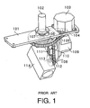
- FIG.1 is a perspective view showing an example of a conventional surveillance camera equipped with a rotation device.
- Pan motor base 101 is secured to, for instance, a housing that is positioned on the back of the ceiling.
- Slip ring 102 is positioned between the housing and pan motor base 101 to provide electrical connections between an electronic circuit board and a tilt mechanism and a camera.
- Pan motor 103 is mounted on pan motor base 101, and to the output shaft thereof pulley 104 is secured.
- Horizontal rotation transmitting timing belt 105 bridges between pulley 104 and pulley 106 secured to the horizontal rotation shaft of slip ring 102. When rotating, the horizontal rotation shaft of pulley produces force in the direction of rotation or of the rotating shaft; bearing 107 receives this force so as to permit smooth rotation of pulley 106.
- Tilt motor base 108 has the configuration of a reverse L shape with horizontal and vertical parts, and a horizontal part of these is secured to pulley 106.
- Tilt motor 109 is fixed to a vertical part of tilt motor holder 108, and to the output shaft thereof pulley 110 is fixed.
- Vertical rotation transmitting timing belt 111 bridges between pulley 110 and another pulley 112 that is fixed to tilt motor holder 108.
- the vertical rotation shaft of pulley 112 produces force in the direction of rotation or of the rotating shaft; bearing 113 receives this force so as to permit smooth rotation of pulley 112 and camera 114 that is fixed to the vertical rotation shaft thereof .
- This pan/tilt mechanism (rotation device) is covered with a transparent or semi-transparent dome.
- the pan/tilt mechanism that enables camera 114 to rotate horizontally and vertically is configured in an L or a reverse L shape.
- this pan/tilt mechanism is equipped with many installation parts including motors 103 and 109 and other parts (such as motor bases 101 and 108, slip ring 102, pulleys 104, 106, 110, and 112, timing belts 105 and 111, etc.), thereby complicating the configuration.
- the horizontal rotation shaft of the pan mechanism and the vertical rotation shaft of the tilt mechanism are provided with bearings 107 and 113, respectively. Installing these bearings 107 and 113 makes the configuration of the parts where these bearings 107 and 113 are installed complex, requires parts to fix bearings 107 and 113, and requires work such as gluing to fix bearings 107 and 113. That is, a conventional rotation device (pan/tilt mechanism) for surveillance cameras has many parts, which results in a complex configuration, and the assembility, parts-compatibility, and the cost down thereof have a certain limit.
- a rotation device with an integral bearing comprising: a non rotating body, integrally formed with an inner ring or an outer ring of the bearing; and, a rotating body, rotatably mounted to the non rotating body and integrally formed with the inner ring or the outer ring of the bearing, wherein a portion of at least one of the non-rotating body and the rotating body integrally incorporates a mechanism.
- a surveillance camera device comprising: a non horizontal rotating body, integrally formed with an inner ring or an outer ring of a first bearing; a horizontal rotating body, rotatably mounted to the non horizontal rotating body and integrally formed with the inner ring or the outer ring of the first bearing; a non vertical rotating body, swingably mounted to the horizontal rotating body and integrally formed with an inner ring or an outer ring of a second bearing; a vertical rotating body, rotatably mounted to the non vertical rotating body and integrally formed with the inner ring and outer ring of the second bearing; and a camera, secured to the vertical rotating body.
- FIG.2 is a configuration diagram showing an example of a surveillance camera comprising a rotation device with an integral bearing according to an embodiment of the invention.
- This surveillance camera 1 comprises camera 3 that performs the recording, and rotation device 2 that enables the camera to rotate so as to change the camera's recording direction.
- rotation device 2 consists chiefly of horizontal rotation mechanism 4 and vertical rotation mechanism 5.
- power source 6 is of a plastic cylinder and secured to ceiling C.
- Fixer 7 that supports rotation device 2 is of a plastic cylinder and detachably mounted to power source 6.
- Dome cover 8 is of transparent plastic and secured to fixer 7. These constitute the outer ward of surveillance camera 1.
- Power circuit board 9 positioned inside power source 6, has a power circuit that is connected to a power source, both not illustrated, and a coaxial cable, not illustrated, for outputting image signals and inputting control signals from the monitors.
- Fixer 7 and base plate 10 of rotation device 2 are connected, and base plate 10 supports horizontal rotation mechanism 4.
- Vertical rotation mechanism 5 is rotatably connected to horizontal rotation mechanism 4 via bearing 11, and camera 3 is mounted to vertical rotation mechanism 5.
- Rotator holder 12 is secured to base plate 10.
- Slip ring 13 is provided inside rotator holder 12, and cylinder 12a of rotator holder 12 that encircles slip ring 13 serves as a bearing inner ring.
- Pan chassis 15 integrated into bearing outer ring 15a is circumscribed to cylinder 12a via rolling ball 14, and comprises horizontal rotation pan motor 16 and gear train 17.
- Gear train 17 comprises: gear 17a, fixed to the motor shaft of horizontal rotation pan motor 16; intermediate gear 17b, fixed to an intermediate shaft that is at right angles with the motor shaft, and output gear 17c that is at right angles to the motor shaft and integrated with pan chassis 15.
- servo circuit board 18 is secured to rotator holder 12.
- Tilt chassis 20 that is integrated with bearing inner ring 20a is secured to pan chassis 15 by means of detachable screw 19.
- Tilt chassis 20 comprises vertical rotation tilt motor 21 and gear train 24.
- Gear train 24 consists chiefly of gear 24a secured to a motor shaft of vertical rotation tilt motor 21, and intermediate gear 24b secured to an intermediate shaft that is at right angles with the motor shaft.
- Bearing outer ring 20b integrated with tilt chassis 20 is attached to tilt shaft 22 that serves as a bearing inner ring via rolling ball 23.
- Tilt shaft 22 is integrated with output gear 24c that configures gear train 24.
- Lens drive circuit board 25 supports recorder 26 that has CCD (Charge Coupled Diode) and lens section 27 consisting of a plurality of lenses, and has digital circuit board 28 and CCD drive circuit board 29 secured thereto.
- CCD Charge Coupled Diode
- inner dome 30 fixed to support member 15b at an end of pan chassis 15 is inner dome 30 that is smaller than dome cover 8 and is made of semi-transparent or non-transparent plastic.
- Inner dome 30 has elongated opening 30a for the movement of lens section 27.
- Power source circuit board 9 and servo circuit board 18 are electrically connected via slip ring 13, while servo circuit 18, CCD drive circuit board 29, digital circuit board 28, and lens drive circuit board 25 are connected by a flex cable.
- This surveillance camera 1 operates following the programs set in advance by a memory or CPU provided on digital circuit board 28.
- horizontal rotation pan motor 16 rotates, pan chassis 15, over gear train 17, rotates around cylinder 12a, and camera 3, over vertical rotation mechanism 5 that is secured to pan chassis 15, rotates horizontally by 360 degrees.
- vertical rotation tilt motor 21 rotates, and, via gear train 24, tilt shaft 22 rotates, and camera 3 rotates by approximately 90 degrees in the vertical plane from the full horizontal position to the full downward position.
- a driving scheme may be employed whereby camera 3 rotates vertically by 180 degrees from the full horizontal position to the full downward position, and thereafter rotates horizontally by 180 degrees and once gain rotates vertically from the full downward position to the full horizontal position.
- Another driving method may be employed whereby, as vertical rotation tilt motor 21 rotates, camera 3 rotates in the vertical plane by 180 degrees continuously, from a full horizontal position to the counter horizontal position past the full downward position.
- lens drive circuit board 25 Upon every horizontal and vertical rotation, the auto focus function and zoom function that lens drive circuit board 25 is equipped with enables focusing and zooming.
- An image taken by lens section 27 is converted into an electrical signal in imaging part 26 that is controlled by CCD drive circuit board 29.
- the electrical signal is converted to a digital signal through digital circuit board 28.
- the digital signal is sent from servo circuit board 18 to power source circuit board 9 through slip ring 13.
- the image's digital and control signals are then multiplexed, and sent to an outside monitor through an unillustrated coaxial cable.
- a person conducts observation by viewing a monitor, and the person is able to perform operation for setting the horizontal and vertical angles of interest and, furthermore able to select the zoom settings of lens section 27.
- FIG. 3A and FIG. 3B are feature diagrams that describe the movement of pan chassis 15 and tilt chassis 20, which are the main chassis used in surveillance camera 1.
- FIG. 3A shows a case where screw 19 that secures pan chassis 15 and tilt chassis 20 at right angles is removed
- FIG. 3B is a diagram wherein pan chassis 15 and tilt chassis 20 are kept horizontally.
- both pan chassis 15 and tilt chassis 20 are configured such that they can be integrated with bearing 11.
- bearing outer ring 15c that is integrated with pan chassis 15 and bearing inner ring 20a that is integrated with tilt chassis 20 are connected by rolling ball 31.
- tilt chassis 20 is secured to pan chassis 15 at right angles by screw 19.
- pan chassis 15 parts including horizontal rotation pan motor 16 are installed to pan chassis 15, and parts including vertical rotation tilt motor 21 are installed to tilt chassis 20.
- screw 19 can be removed, and with bearing 11 being a supporting point, tilt chassis 20 can be rotated to an angle of interest in relation to pan chassis 15.
- pan chassis 15 and tilt chassis 20 are kept in a horizontal state, so that the parts are installed from the same direction.
- the installation of the parts can be executed from both directions at ease.
- inner and outer rings of a bearing are integrated with parts installation platform such as chassis, so that the parts installation platform acquires the functions of a bearing, thereby reducing the number of parts, simplifying the configuration, improving the assembility and parts-compatibility, and reducing the cost.
- the chassis that serves as the installation platforms for parts for horizontal rotation and vertical rotation may be configured such that each chassis is capable of swinging in relation to the other, so as to improve assembility upon installation of parts and parts compatibility.
- the above embodiment is a rotation device with an integral bearing for use in surveillance cameras
- the use of the present invention is not limited to the above usage and suit for use in various machinery and electronic equipments.
- the present invention realizes reduced number of parts, simplified configuration, improved assembility and parts-compatibility, and reduced cost.
Landscapes
- Physics & Mathematics (AREA)
- General Physics & Mathematics (AREA)
- Business, Economics & Management (AREA)
- Emergency Management (AREA)
- Studio Devices (AREA)
- Accessories Of Cameras (AREA)
- Rolling Contact Bearings (AREA)
- Connection Of Motors, Electrical Generators, Mechanical Devices, And The Like (AREA)
Abstract
Description
Claims (8)
- A rotation device with an integral bearing, comprising:a non-rotating body (12, 20), integrally formed with an inner ring(12a) or an outer ring(20b) of the bearing; anda rotating body(15, 22), rotatably mounted to the non-rotating body (15, 22) and integrally formed with the outer ring(15a) or the inner ring(22) of the bearing, andwherein a portion of at least one of the non-rotating body(12, 20) and the rotating body(15, 22) integrally incorporates a mechanism.
- The rotation device with an integral bearing according to claim 1, wherein the mechanism is a driving part that enables rotational movement of the rotating body(15, 22).
- The rotation device with an integral bearing according to claim 2, wherein the driving part comprises :wherein at least one of the force generating part (16, 21) and the force transmitting part(17, 24) is mounted to the rotating body(15, 22).a force generating part(16, 21) that generates rotational force;a force transmitting part(17, 24) that transmits the generated rotational force to the rotating body(15, 22),
- A rotation device with an integral bearing, comprising two rotation devices(4, 5) with an integral bearing as claimed in claim 1 as components, wherein the mechanism is a connecting part(11) that connects the two component rotation devices(4, 5).
- The rotation device with an integral bearing according to claim 4, wherein the connecting part(11) connects the two component rotation devices(4, 5) in an L or a reverse L shape.
- The rotation device with an integral bearing according to claim 4, wherein the connecting part(11) rotatably connects the two component rotation devices(4, 5).
- The rotation device with an integral bearing according to claim 6, wherein the rotating body(15) of one component rotation device(4) rotates horizontally and the rotating body(22) of the other component rotation device(5) rotates vertically.
- A surveillance camera device comprising:a non-horizontal rotating body(12), integrally formed with an inner ring(12a) or an outer ring of a first bearing;a horizontal rotating body(15), rotatably mounted to the non-horizontal rotating body(12) and integrally formed with the outer ring(15a) or the inner ring of the first bearing;a non-vertical rotating body (20), swingably mounted to the horizontal rotating body (15) and integrally formed with an inner ring or an outer ring(20b) of a second bearing;a vertical rotating body(22), rotatably mounted to the non-vertical rotating body(20) and integrally formed with the outer ring and the inner ring(22) of the second bearing; anda camera(3), secured to the vertical rotating body.
Applications Claiming Priority (2)
| Application Number | Priority Date | Filing Date | Title |
|---|---|---|---|
| JP2002107912 | 2002-04-10 | ||
| JP2002107912A JP2003301994A (en) | 2002-04-10 | 2002-04-10 | Bearing integrated rotation device |
Publications (3)
| Publication Number | Publication Date |
|---|---|
| EP1353304A2 true EP1353304A2 (en) | 2003-10-15 |
| EP1353304A3 EP1353304A3 (en) | 2004-03-24 |
| EP1353304A9 EP1353304A9 (en) | 2004-06-09 |
Family
ID=28449948
Family Applications (1)
| Application Number | Title | Priority Date | Filing Date |
|---|---|---|---|
| EP03008201A Withdrawn EP1353304A3 (en) | 2002-04-10 | 2003-04-08 | rotation device with an integral bearing |
Country Status (4)
| Country | Link |
|---|---|
| US (1) | US20030194230A1 (en) |
| EP (1) | EP1353304A3 (en) |
| JP (1) | JP2003301994A (en) |
| CN (1) | CN1450296A (en) |
Cited By (1)
| Publication number | Priority date | Publication date | Assignee | Title |
|---|---|---|---|---|
| US9346075B2 (en) | 2011-08-26 | 2016-05-24 | Nordson Corporation | Modular jetting devices |
Families Citing this family (22)
| Publication number | Priority date | Publication date | Assignee | Title |
|---|---|---|---|---|
| JP3906844B2 (en) * | 2004-01-13 | 2007-04-18 | ソニー株式会社 | Imaging device |
| JP4514525B2 (en) * | 2004-06-11 | 2010-07-28 | パナソニック株式会社 | Camera device |
| JP4594663B2 (en) * | 2004-06-30 | 2010-12-08 | 本田技研工業株式会社 | Security robot |
| JP2006015436A (en) * | 2004-06-30 | 2006-01-19 | Honda Motor Co Ltd | Surveillance robot |
| KR100718087B1 (en) * | 2005-08-19 | 2007-05-16 | 삼성전자주식회사 | Surveillance camera |
| US7841783B2 (en) * | 2006-02-16 | 2010-11-30 | Brandebury Tool Company, Inc. | Miniaturized turret-mounted camera assembly |
| CN100474103C (en) * | 2006-11-10 | 2009-04-01 | 深圳市傲视群雄科技有限公司 | Intelligent-controlled camera head of cloud platform |
| CN101191982B (en) * | 2006-11-22 | 2011-03-30 | 乐金电子(昆山)电脑有限公司 | Photographic camera electric rocking-pickup device |
| US8137007B1 (en) * | 2008-01-11 | 2012-03-20 | Brandebury Tool Company, Inc. | Miniaturized turret-mounted camera assembly |
| US8325229B2 (en) * | 2008-11-26 | 2012-12-04 | Robert Bosch Gmbh | Camera having a slip ring and pan-tilt mechanism |
| EP2400343B1 (en) * | 2009-02-19 | 2018-05-30 | Panasonic Corporation | Camera device and method for assembling camera device |
| WO2013035637A1 (en) * | 2011-09-06 | 2013-03-14 | 富士フイルム株式会社 | Television lens device |
| US9264595B2 (en) | 2011-10-27 | 2016-02-16 | Robert Bosch Gmbh | Arrangement for adjustably mounting a camera |
| US9106814B2 (en) * | 2012-11-14 | 2015-08-11 | The United States of America as represented by the Federal Bureau of Investigation, Dept. of Justice | Apparatuses for rotating a sensing device |
| KR101883474B1 (en) * | 2013-01-29 | 2018-07-30 | 한화에어로스페이스 주식회사 | A rotating support assembly and a photographing apparatus comprising the same |
| JP6283909B2 (en) * | 2013-03-01 | 2018-02-28 | パナソニックIpマネジメント株式会社 | Camera device and method of controlling camera device |
| JP2016005252A (en) * | 2014-06-19 | 2016-01-12 | パナソニックIpマネジメント株式会社 | Imaging apparatus |
| CN107864330B (en) * | 2016-09-22 | 2020-06-16 | 光宝电子(广州)有限公司 | Camera and setting method and adjusting method thereof |
| KR102489238B1 (en) * | 2016-09-26 | 2023-01-16 | 한화테크윈 주식회사 | Camera assembly for indoor and outdoor use |
| US11268651B2 (en) * | 2019-09-19 | 2022-03-08 | Anduril Industries, Inc. | Pan tilt unit |
| JP2022108866A (en) * | 2021-01-14 | 2022-07-27 | キヤノン株式会社 | Imaging device |
| CN113775886A (en) * | 2021-09-22 | 2021-12-10 | 哈尔滨学院 | Device for recognizing facial expressions and intelligently allocating music to adjust |
Family Cites Families (9)
| Publication number | Priority date | Publication date | Assignee | Title |
|---|---|---|---|---|
| US3869295A (en) * | 1970-03-30 | 1975-03-04 | Andrew D Bowles | Uniform lightweight concrete and plaster |
| US4031285A (en) * | 1971-10-21 | 1977-06-21 | Miller Charles H | Lightweight, reinforced foamed organic polymer and cementitious material structure |
| US5028997A (en) * | 1989-07-20 | 1991-07-02 | Elbex Video Kabushiki Kaisha | Television camera apparatus |
| US5463432A (en) * | 1993-05-24 | 1995-10-31 | Kahn; Philip | Miniature pan/tilt tracking mount |
| US5598207A (en) * | 1994-04-12 | 1997-01-28 | Hughes Electronics | Camera pointing mechanism using proximate magnetic sensing |
| US5627616A (en) * | 1994-06-22 | 1997-05-06 | Philips Electronics North America Corporation | Surveillance camera system |
| US5622556A (en) * | 1994-12-19 | 1997-04-22 | Shulman; David M. | Lightweight, low water content cementitious compositions and methods of their production and use |
| JPH11215405A (en) * | 1998-01-26 | 1999-08-06 | Matsushita Electric Ind Co Ltd | Component mounting member and component mounting method |
| US6793415B2 (en) * | 2001-11-30 | 2004-09-21 | Pelco | Slip ring assembly and method |
-
2002
- 2002-04-10 JP JP2002107912A patent/JP2003301994A/en active Pending
-
2003
- 2003-03-28 US US10/400,800 patent/US20030194230A1/en not_active Abandoned
- 2003-04-08 CN CN03109512.7A patent/CN1450296A/en active Pending
- 2003-04-08 EP EP03008201A patent/EP1353304A3/en not_active Withdrawn
Cited By (4)
| Publication number | Priority date | Publication date | Assignee | Title |
|---|---|---|---|---|
| US9346075B2 (en) | 2011-08-26 | 2016-05-24 | Nordson Corporation | Modular jetting devices |
| US9808825B2 (en) | 2011-08-26 | 2017-11-07 | Nordson Corporation | Modular jetting devices |
| US9808826B2 (en) | 2011-08-26 | 2017-11-07 | Nordson Corporation | Modular jetting devices |
| US10300505B2 (en) | 2011-08-26 | 2019-05-28 | Nordson Corporation | Modular jetting devices |
Also Published As
| Publication number | Publication date |
|---|---|
| EP1353304A9 (en) | 2004-06-09 |
| EP1353304A3 (en) | 2004-03-24 |
| CN1450296A (en) | 2003-10-22 |
| JP2003301994A (en) | 2003-10-24 |
| US20030194230A1 (en) | 2003-10-16 |
Similar Documents
| Publication | Publication Date | Title |
|---|---|---|
| EP1353304A2 (en) | Rotation device with an integral bearing | |
| CN107528999B (en) | surveillance camera system | |
| KR100770866B1 (en) | Camera lens module with auto focus | |
| US8203597B2 (en) | Panoramic camera | |
| CN109428508B (en) | Image pickup apparatus | |
| US6200042B1 (en) | Parts-mounted member and method of mounting parts | |
| US7197240B2 (en) | Camera module and portable terminal equipped with the camera module | |
| JP2007108373A (en) | Electric zoom device | |
| KR20050089510A (en) | Pan-tilt dome type camera | |
| US7116901B2 (en) | Zoom finder drive mechanisms | |
| US7321726B2 (en) | Camera module and portable terminal equipped with the camera module | |
| JP4131945B2 (en) | Imaging apparatus and manufacturing method thereof | |
| JP2006030256A (en) | Focus adjustment method and focus adjustment apparatus for imaging apparatus | |
| US6266090B1 (en) | Device for controlling a rotation of a lens in a digital camera | |
| JP2006325070A (en) | Surveillance camera device and tilt operation end setting method thereof | |
| JP2002344774A (en) | Imaging unit | |
| JP2010276636A (en) | Imaging device | |
| JP7150492B2 (en) | Imaging device | |
| KR200352613Y1 (en) | Pan-tilt dome type camera | |
| JP2009049854A (en) | Compound eye photography device | |
| CN223038283U (en) | Adapter ring capable of realizing automatic and manual focusing of manual lens | |
| JPH10319298A (en) | Lens barrel with built-in motor | |
| KR960032069A (en) | How to adjust the camera and its focus | |
| JPH0628407B2 (en) | Imaging device | |
| JP2002040553A (en) | Camera device with head |
Legal Events
| Date | Code | Title | Description |
|---|---|---|---|
| PUAI | Public reference made under article 153(3) epc to a published international application that has entered the european phase |
Free format text: ORIGINAL CODE: 0009012 |
|
| AK | Designated contracting states |
Kind code of ref document: A2 Designated state(s): AT BE BG CH CY CZ DE DK EE ES FI FR GB GR HU IE IT LI LU MC NL PT SE SI SK TR |
|
| AX | Request for extension of the european patent |
Extension state: AL LT LV MK RO |
|
| PUAL | Search report despatched |
Free format text: ORIGINAL CODE: 0009013 |
|
| AK | Designated contracting states |
Kind code of ref document: A3 Designated state(s): AT BE BG CH CY CZ DE DK EE ES FI FR GB GR HU IE IT LI LU MC NL PT SE SI SK TR |
|
| AX | Request for extension of the european patent |
Extension state: AL LT LV MK RO |
|
| RAP1 | Party data changed (applicant data changed or rights of an application transferred) |
Owner name: MATSUSHITA ELECTRIC INDUSTRIAL CO., LTD. |
|
| RTI1 | Title (correction) |
Free format text: ROTATION DEVICE WITH AN INTEGRAL BEARING |
|
| STAA | Information on the status of an ep patent application or granted ep patent |
Free format text: STATUS: THE APPLICATION HAS BEEN WITHDRAWN |
|
| 18W | Application withdrawn |
Effective date: 20040909 |