EP1353243A2 - Xerographic fusing apparatus - Google Patents
Xerographic fusing apparatus Download PDFInfo
- Publication number
- EP1353243A2 EP1353243A2 EP03251913A EP03251913A EP1353243A2 EP 1353243 A2 EP1353243 A2 EP 1353243A2 EP 03251913 A EP03251913 A EP 03251913A EP 03251913 A EP03251913 A EP 03251913A EP 1353243 A2 EP1353243 A2 EP 1353243A2
- Authority
- EP
- European Patent Office
- Prior art keywords
- sheet
- nip
- roll
- marking station
- guide member
- Prior art date
- Legal status (The legal status is an assumption and is not a legal conclusion. Google has not performed a legal analysis and makes no representation as to the accuracy of the status listed.)
- Withdrawn
Links
- 239000000758 substrate Substances 0.000 description 6
- 238000010438 heat treatment Methods 0.000 description 4
- 239000000463 material Substances 0.000 description 4
- 238000000034 method Methods 0.000 description 4
- 230000001052 transient effect Effects 0.000 description 4
- 230000007547 defect Effects 0.000 description 3
- 238000002955 isolation Methods 0.000 description 2
- 230000002708 enhancing effect Effects 0.000 description 1
- 238000003384 imaging method Methods 0.000 description 1
- 230000007246 mechanism Effects 0.000 description 1
- 238000011144 upstream manufacturing Methods 0.000 description 1
Images


Classifications
-
- G—PHYSICS
- G03—PHOTOGRAPHY; CINEMATOGRAPHY; ANALOGOUS TECHNIQUES USING WAVES OTHER THAN OPTICAL WAVES; ELECTROGRAPHY; HOLOGRAPHY
- G03G—ELECTROGRAPHY; ELECTROPHOTOGRAPHY; MAGNETOGRAPHY
- G03G15/00—Apparatus for electrographic processes using a charge pattern
- G03G15/20—Apparatus for electrographic processes using a charge pattern for fixing, e.g. by using heat
- G03G15/2003—Apparatus for electrographic processes using a charge pattern for fixing, e.g. by using heat using heat
- G03G15/2014—Apparatus for electrographic processes using a charge pattern for fixing, e.g. by using heat using heat using contact heat
- G03G15/2017—Structural details of the fixing unit in general, e.g. cooling means, heat shielding means
- G03G15/2028—Structural details of the fixing unit in general, e.g. cooling means, heat shielding means with means for handling the copy material in the fixing nip, e.g. introduction guides, stripping means
Definitions
- fusing In electrostatographic printing, commonly known as xerographic or printing or copying, an important process step is known as "fusing.”
- dry marking material such as toner
- an imaging substrate such as a sheet of paper
- heat and/or pressure in order to melt or otherwise fuse the toner permanently on the substrate.
- durable, non-smudging images are rendered on the substrates.
- the most common design of a fusing apparatus as used in commercial printers includes two rolls, typically called a fuser roll and a pressure roll, forming a nip therebetween for the passage of the substrate therethrough.
- the fuser roll further includes, disposed on the interior thereof, one or more heating elements, which radiate heat in response to a current being passed therethrough.
- the heat from the heating elements passes through the surface of the fuser roll, which in turn contacts the side of the substrate having the image to be fused, so that a combination of heat and pressure successfully fuses the image.
- US Patent 5,822,668 describes a general configuration of a fuser module as used in a xerographic printer.
- One practical problem with certain compact designs of xerographic or other printers relates to the unintended transfer of mechanical energy, such as vibration or a torque transient, originating at the fusing apparatus and travelling through a print sheet while another portion of the print sheet is still receiving marking material (e.g., toner or ink) at the marking station.
- This vibration or other mechanical energy can cause a print defect such as smearing at the marking station.
- a printing apparatus comprising a marking station; a nip, formed by a first roll and a second roll; means for directing a lead edge of the sheet toward the nip at an angle which causes the sheet to form an arc between the marking station and the nip as the lead edge of the sheet enters the nip; and means for straightening the sheet between the marking station and the nip as a trail edge of the sheet substantially exits the marking station.
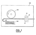
- FIG. 1 is a simplified elevational view showing the essential portions of an electrostatographic printer, such as a xerographic printer or copier, relevant to the present invention.
- a printing apparatus 100 which can be in the form of a digital or analog copier, "laser printer,” ionographic printer, or other device, includes mechanisms which draw substrates, such as sheets of paper, from a stack 102 and cause each sheet to obtain a toner image from the surface of a charge receptor 104.
- the toner image is transferred from the charge receptor 104 to the sheet by a transfer corotron 106, and the sheet is detached from the surface of the charge receptor 104 by a detack corotron Once a particular sheet obtains marking material from charge receptor 104, the sheet is caused to pass through a fusing apparatus such as generally indicated as 10.
- a typical design of a fusing apparatus 10 includes a fuser roll 12 and a pressure roll 14.
- Fuser roll 12 and pressure roll 14 cooperate to exert pressure against each other across a nip formed therebetween. When a sheet passes through the nip, the pressure of the fuser roll against the pressure roll contributes to the fusing of the image on a sheet.
- Fuser roll 12 further includes means for heating the surface of the roll, so that heat can be supplied to the sheet in addition to the pressure, further enhancing the fusing process.
- the fuser roll 12, having the heating means associated therewith is the roll which contacts the side of the sheet having the image desired to be fused.
- a practical problem with certain compact designs of xerographic or other printers relates to the unintended transfer of mechanical energy, such as vibration, originating at the fusing apparatus 10 and travelling through a print sheet while another portion of the print sheet is still receiving marking material (e.g., toner or ink) at the marking station such as charge receptor 104.
- marking material e.g., toner or ink
- Figures 2 and 3 are elevational views of a print sheet S passing from a charge receptor 104 to a fusing apparatus 10 showing a method and apparatus which addresses the problem of transfer of mechanical energy through a print sheet.
- a movable guide member, or plate which extends substantially the length of the rolls 12, 14.
- guide plate 20 is operatively associated with a bell crank 24, which in turn is associated with a solenoid 26 and a tension spring 28.
- the solenoid 28, through the bell crank 24, operates to selectably position guide plate 20 relative to the nip.
- Solenoid 28 is controlled via a control system (not shown) which is coordinated with the overall operation of the printing apparatus.
- solenoid 26 is operated to position guide plate 20 so that a lead edge of the sheet S emerging from the charge receptor 104 (and still having a portion in contact with charge receptor 104) is directed toward the nip at an angle which causes the sheet to form an arc between the charge receptor 104 and the nip as the lead edge of the sheet enters the nip.
- Figure 3 shows the elements of Figure 2, after the sheet S has begun to travel through the nip and the trail edge of the sheet has cleared the charge receptor 104.
- solenoid 26 is operated to position to guide plate 20 so that the arc shown in Figure 2 is straightened and the balance of sheet S is moved straight through the nip.
- the control of the solenoid 26 or other device can be modified for optimal performance.
- the guide plate 20 can be withdrawn (toward the position in Figure 3) to straighten the sheet at any time during the passage of a sheet S through the system, e.g., at some predetermined time before the trail edge of the sheet is expected to exit the marking station; in response to the trail edge being detected as passing a certain point in the sheet path; or in response to some detected physical condition such as a lack of vibration in the apparatus.
- the motion of the guide plate 20 between the Figure 2 and Figure 3 positions can be, in various parts of a sheet-feeding cycle, relatively gradual or relatively abrupt.
- the illustrated embodiment shows guide plate 20 being positionable via a solenoid
- other electromechanical devices for effecting the positioning are readily contemplated, such as a cam mounted on a rotating axle.
- the fusing apparatus is in the form of a module (such as 10 in Figure 1) which is readily removable and installable in a larger apparatus, the electromechanical device can be provided as part of the module, or the device can be part of the larger apparatus.
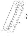
- Figure 4 is a perspective view showing, in isolation, the rollers 12, 14 and a mounted guide plate 20.
- the guide plate 20 is pivotably mounted coaxially with roll 14.
- the guide plate 20 can be pivotably mounted relative to some other axis, or can be slidably mounted. If the fusing apparatus is in the form of a module (such as 10 in Figure 1) which is readily removable and installable in a larger apparatus, the guide plate 20 can be provided as part of the module, or the guide plate can be part of the larger apparatus.
Landscapes
- Physics & Mathematics (AREA)
- General Physics & Mathematics (AREA)
- Fixing For Electrophotography (AREA)
- Paper Feeding For Electrophotography (AREA)
- Feeding Of Articles By Means Other Than Belts Or Rollers (AREA)
Abstract
Description
- In electrostatographic printing, commonly known as xerographic or printing or copying, an important process step is known as "fusing." In the fusing step of the xerographic process, dry marking material, such as toner, which has been placed in imagewise fashion on an imaging substrate, such as a sheet of paper, is subjected to heat and/or pressure in order to melt or otherwise fuse the toner permanently on the substrate. In this way, durable, non-smudging images are rendered on the substrates.
Currently, the most common design of a fusing apparatus as used in commercial printers includes two rolls, typically called a fuser roll and a pressure roll, forming a nip therebetween for the passage of the substrate therethrough. Typically, the fuser roll further includes, disposed on the interior thereof, one or more heating elements, which radiate heat in response to a current being passed therethrough. The heat from the heating elements passes through the surface of the fuser roll, which in turn contacts the side of the substrate having the image to be fused, so that a combination of heat and pressure successfully fuses the image. US Patent 5,822,668 describes a general configuration of a fuser module as used in a xerographic printer. - One practical problem with certain compact designs of xerographic or other printers relates to the unintended transfer of mechanical energy, such as vibration or a torque transient, originating at the fusing apparatus and travelling through a print sheet while another portion of the print sheet is still receiving marking material (e.g., toner or ink) at the marking station. This vibration or other mechanical energy can cause a print defect such as smearing at the marking station.
- According to an aspect of the present invention, there is provided a printing apparatus, comprising a marking station; a nip, formed by a first roll and a second roll; means for directing a lead edge of the sheet toward the nip at an angle which causes the sheet to form an arc between the marking station and the nip as the lead edge of the sheet enters the nip; and means for straightening the sheet between the marking station and the nip as a trail edge of the sheet substantially exits the marking station.
- A particular embodiment in accordance with this invention will now be described with reference to the accompanying drawings; in which:-
- Figure 1 is a simplified elevational view showing the essential portions of an electrostatographic printer, such as a xerographic printer or copier;
- Figures 2 and 3 are elevational views of a print sheet passing from a charge receptor to a fusing apparatus; and,
- Figure 4 is a perspective view showing, in isolation, fuser rolls and a pivotably mounted guide member.
-
- Figure 1 is a simplified elevational view showing the essential portions of an electrostatographic printer, such as a xerographic printer or copier, relevant to the present invention. A
printing apparatus 100, which can be in the form of a digital or analog copier, "laser printer," ionographic printer, or other device, includes mechanisms which draw substrates, such as sheets of paper, from astack 102 and cause each sheet to obtain a toner image from the surface of acharge receptor 104. The toner image is transferred from thecharge receptor 104 to the sheet by atransfer corotron 106, and the sheet is detached from the surface of thecharge receptor 104 by a detack corotron Once a particular sheet obtains marking material fromcharge receptor 104, the sheet is caused to pass through a fusing apparatus such as generally indicated as 10. - A typical design of a
fusing apparatus 10 includes afuser roll 12 and apressure roll 14.Fuser roll 12 andpressure roll 14 cooperate to exert pressure against each other across a nip formed therebetween. When a sheet passes through the nip, the pressure of the fuser roll against the pressure roll contributes to the fusing of the image on a sheet.Fuser roll 12 further includes means for heating the surface of the roll, so that heat can be supplied to the sheet in addition to the pressure, further enhancing the fusing process. Typically, thefuser roll 12, having the heating means associated therewith, is the roll which contacts the side of the sheet having the image desired to be fused. - As mentioned above, a practical problem with certain compact designs of xerographic or other printers relates to the unintended transfer of mechanical energy, such as vibration, originating at the
fusing apparatus 10 and travelling through a print sheet while another portion of the print sheet is still receiving marking material (e.g., toner or ink) at the marking station such ascharge receptor 104. This vibration or other mechanical energy can cause a print defect. - Figures 2 and 3 are elevational views of a print sheet S passing from a
charge receptor 104 to afusing apparatus 10 showing a method and apparatus which addresses the problem of transfer of mechanical energy through a print sheet. In addition to the elements described above, there is provided, just upstream of the nip formed byrolls rolls upper input guide 22. In this embodiment,guide plate 20 is operatively associated with abell crank 24, which in turn is associated with asolenoid 26 and atension spring 28. Thesolenoid 28, through thebell crank 24, operates to selectablyposition guide plate 20 relative to the nip. Solenoid 28 is controlled via a control system (not shown) which is coordinated with the overall operation of the printing apparatus. - With reference to Figure 2,
solenoid 26 is operated to positionguide plate 20 so that a lead edge of the sheet S emerging from the charge receptor 104 (and still having a portion in contact with charge receptor 104) is directed toward the nip at an angle which causes the sheet to form an arc between thecharge receptor 104 and the nip as the lead edge of the sheet enters the nip. - While a sheet is passing through a printing machine with a portion thereof near or in the nip and another portion thereof still in contact with
charge receptor 104, it is possible that vibration or other mechanical energy from the fusing apparatus can travel through the sheet and cause a print defect for the portion of the sheet still in contact with the marking station. More specifically, when the sheet enters the fuser nip a large torque transient is imparted to the fuser nip and subsequent drive system. As a result of this sudden transient the whole system slows down momentarily, and the sheet decelerates as well. If the sheet is straight from the fuser nip back to the transfer zone, this deceleration will be directly seen at transfer, causing a smear as the sheet momentarily is moving backwards. If, as in Figure 2, the sheet is formed into an arc between the fuser nip and the transfer zone, then this deceleration simply pushes back on the arc, which momentarily makes it higher, but does not affect the image in the transfer zone. This buckle or arc thus serves to dampen the energy due to the torque transient. - Figure 3 shows the elements of Figure 2, after the sheet S has begun to travel through the nip and the trail edge of the sheet has cleared the
charge receptor 104. Here,solenoid 26 is operated to position to guideplate 20 so that the arc shown in Figure 2 is straightened and the balance of sheet S is moved straight through the nip. - As part of a larger control system governing the entire printing apparatus, the control of the
solenoid 26 or other device can be modified for optimal performance. For instance, once theguide plate 20 is positioned to create an arc in the sheet (as in Figure 2), the guide plate can be withdrawn (toward the position in Figure 3) to straighten the sheet at any time during the passage of a sheet S through the system, e.g., at some predetermined time before the trail edge of the sheet is expected to exit the marking station; in response to the trail edge being detected as passing a certain point in the sheet path; or in response to some detected physical condition such as a lack of vibration in the apparatus. Also, depending on a specific design, the motion of theguide plate 20 between the Figure 2 and Figure 3 positions can be, in various parts of a sheet-feeding cycle, relatively gradual or relatively abrupt. - Although the illustrated embodiment shows
guide plate 20 being positionable via a solenoid, other electromechanical devices for effecting the positioning are readily contemplated, such as a cam mounted on a rotating axle. If the fusing apparatus is in the form of a module (such as 10 in Figure 1) which is readily removable and installable in a larger apparatus, the electromechanical device can be provided as part of the module, or the device can be part of the larger apparatus. - Figure 4 is a perspective view showing, in isolation, the
rollers guide plate 20. In this embodiment, theguide plate 20 is pivotably mounted coaxially withroll 14. In alternate embodiments, theguide plate 20 can be pivotably mounted relative to some other axis, or can be slidably mounted. If the fusing apparatus is in the form of a module (such as 10 in Figure 1) which is readily removable and installable in a larger apparatus, theguide plate 20 can be provided as part of the module, or the guide plate can be part of the larger apparatus.
Claims (7)
- A printing apparatus, comprising:a marking station (104,106,108);a nip, formed by a first roll (12) and a second roll (14);means (20) for directing a lead edge of a sheet (5) toward the nip at an angle which causes the sheet to form an arc between the marking station (104,106,108) and the nip as the lead edge of the sheet (S) enters the nip; and,means (24,26) for straightening the sheet (S) between the marking station (104,106,108) and the nip as a trail edge of the sheet (S) substantially exits the marking station (104,106,108).
- An apparatus according to claim 1, further comprising;
a guide member (20); and,
the directing means including means (24,26,28) for positioning the guide member (20) near the nip. - An apparatus according to claim 2, wherein the straightening means including means (26) for withdrawing the guide member (20).
- An apparatus according to claim 2 or 3, wherein the guide member (20) is pivotably mounted.
- An apparatus according to claim 4, wherein the guide member (20) is pivotably mounted about an axis coaxial with the first roll (12).
- An apparatus according to any one of the preceding claims, wherein the first roll and the second roll form a fusing apparatus.
- An apparatus according to any one of the preceding claims, wherein the marking station includes an image-bearing charge receptor (104).
Applications Claiming Priority (2)
| Application Number | Priority Date | Filing Date | Title |
|---|---|---|---|
| US119430 | 2002-04-09 | ||
| US10/119,430 US6661989B2 (en) | 2002-04-09 | 2002-04-09 | Xerographic fusing apparatus with input sheet guide |
Publications (2)
| Publication Number | Publication Date |
|---|---|
| EP1353243A2 true EP1353243A2 (en) | 2003-10-15 |
| EP1353243A3 EP1353243A3 (en) | 2004-07-28 |
Family
ID=28453987
Family Applications (1)
| Application Number | Title | Priority Date | Filing Date |
|---|---|---|---|
| EP03251913A Withdrawn EP1353243A3 (en) | 2002-04-09 | 2003-03-27 | Xerographic fusing apparatus |
Country Status (5)
| Country | Link |
|---|---|
| US (1) | US6661989B2 (en) |
| EP (1) | EP1353243A3 (en) |
| JP (1) | JP2003307960A (en) |
| BR (1) | BR0300979A (en) |
| MX (1) | MXPA03003028A (en) |
Cited By (2)
| Publication number | Priority date | Publication date | Assignee | Title |
|---|---|---|---|---|
| EP1731969A3 (en) * | 2005-03-29 | 2006-12-27 | Canon Kabushiki Kaisha | Image forming apparatus for varying a loop in the copy medium in the transport path between transfer and fixing portions |
| EP3101480A1 (en) * | 2015-06-05 | 2016-12-07 | Samsung Electronics Co., Ltd | Image forming apparatus and control method for the same |
Families Citing this family (14)
| Publication number | Priority date | Publication date | Assignee | Title |
|---|---|---|---|---|
| US6892047B1 (en) * | 2002-09-25 | 2005-05-10 | Eastman Kodak Company | Air baffle for paper travel path within an electrophotographic machine |
| KR100461594B1 (en) * | 2003-03-04 | 2004-12-18 | 삼성전자주식회사 | Paper guide for an electric photographic image formming machine |
| JP2005018029A (en) * | 2003-05-30 | 2005-01-20 | Ricoh Printing Systems Ltd | Image forming apparatus |
| US7054571B2 (en) * | 2004-01-14 | 2006-05-30 | Lexmark International, Inc. | Method of driving a fuser roll in an electrophotographic printer |
| JP4112518B2 (en) * | 2004-03-22 | 2008-07-02 | シャープ株式会社 | Image forming apparatus |
| US7432818B2 (en) * | 2006-04-26 | 2008-10-07 | Xerox Corporation | Printing apparatus including components equipped with RFID wear monitoring devices |
| US7432812B2 (en) * | 2006-04-26 | 2008-10-07 | Xerox Corporation | Passive radio frequency device for monitoring wear in components |
| JP5445917B2 (en) * | 2008-09-08 | 2014-03-19 | 株式会社リコー | Image forming apparatus |
| JP5326958B2 (en) * | 2009-09-15 | 2013-10-30 | 株式会社リコー | Fixing apparatus and image forming apparatus |
| JP4995247B2 (en) * | 2009-10-07 | 2012-08-08 | 株式会社沖データ | Image forming apparatus |
| JP5835646B2 (en) * | 2011-06-30 | 2015-12-24 | 株式会社リコー | Guide device, fixing device, and image forming apparatus |
| US8548346B2 (en) | 2011-10-14 | 2013-10-01 | Xerox Corporation | Label press fuser algorithm for feeding a continuous roll of label material through a sheet fed printing device |
| US20160370738A1 (en) * | 2015-06-16 | 2016-12-22 | Ricoh Company, Ltd. | Recording medium conveyance guide device, transfer device, and image forming apparatus |
| KR20180044571A (en) * | 2016-10-24 | 2018-05-03 | 에스프린팅솔루션 주식회사 | Fusing device and image forming apparatus having the same |
Citations (3)
| Publication number | Priority date | Publication date | Assignee | Title |
|---|---|---|---|---|
| JPH07234604A (en) * | 1994-02-23 | 1995-09-05 | Canon Inc | Image forming device |
| US5771434A (en) * | 1996-05-08 | 1998-06-23 | Fuji Xerox Co., Ltd. | Image forming apparatus |
| EP0881547A2 (en) * | 1997-05-26 | 1998-12-02 | Konica Corporation | Electrophotographic type image forming apparatus |
Family Cites Families (7)
| Publication number | Priority date | Publication date | Assignee | Title |
|---|---|---|---|---|
| JPS565566A (en) * | 1979-06-28 | 1981-01-21 | Konishiroku Photo Ind Co Ltd | Transfer paper conveying device |
| US4876576A (en) * | 1987-04-25 | 1989-10-24 | Kabushiki Kaisha Toshiba | Device for changing sheet shape before entry into fuser nip |
| JPS63285572A (en) * | 1987-05-18 | 1988-11-22 | Ricoh Co Ltd | Electrophotographic device |
| DE3808477A1 (en) * | 1988-03-14 | 1989-09-28 | Siemens Ag | DEVICE FOR SMOOTHING SINGLE SHEETS IN NON-MECHANICAL PRINTING AND COPYING DEVICES |
| JPH0463465U (en) * | 1990-10-15 | 1992-05-29 | ||
| JPH07146625A (en) * | 1993-11-13 | 1995-06-06 | Asahi Optical Co Ltd | Printer that uses continuous paper |
| US5822668A (en) | 1997-04-11 | 1998-10-13 | Xerox Coporation | Fuser subsystem module for an electrophotographic printer which pivots open for jam clearance |
-
2002
- 2002-04-09 US US10/119,430 patent/US6661989B2/en not_active Expired - Fee Related
-
2003
- 2003-03-27 EP EP03251913A patent/EP1353243A3/en not_active Withdrawn
- 2003-03-31 BR BR0300979-3A patent/BR0300979A/en not_active Application Discontinuation
- 2003-04-02 JP JP2003098878A patent/JP2003307960A/en active Pending
- 2003-04-07 MX MXPA03003028A patent/MXPA03003028A/en active IP Right Grant
Patent Citations (3)
| Publication number | Priority date | Publication date | Assignee | Title |
|---|---|---|---|---|
| JPH07234604A (en) * | 1994-02-23 | 1995-09-05 | Canon Inc | Image forming device |
| US5771434A (en) * | 1996-05-08 | 1998-06-23 | Fuji Xerox Co., Ltd. | Image forming apparatus |
| EP0881547A2 (en) * | 1997-05-26 | 1998-12-02 | Konica Corporation | Electrophotographic type image forming apparatus |
Cited By (4)
| Publication number | Priority date | Publication date | Assignee | Title |
|---|---|---|---|---|
| EP1731969A3 (en) * | 2005-03-29 | 2006-12-27 | Canon Kabushiki Kaisha | Image forming apparatus for varying a loop in the copy medium in the transport path between transfer and fixing portions |
| US7409172B2 (en) | 2005-03-29 | 2008-08-05 | Canon Kabushiki Kaisha | Image forming apparatus |
| EP3101480A1 (en) * | 2015-06-05 | 2016-12-07 | Samsung Electronics Co., Ltd | Image forming apparatus and control method for the same |
| US9897951B2 (en) | 2015-06-05 | 2018-02-20 | S-Printing Solution Co., Ltd. | Image forming apparatus and control method for the same |
Also Published As
| Publication number | Publication date |
|---|---|
| US6661989B2 (en) | 2003-12-09 |
| BR0300979A (en) | 2004-09-08 |
| EP1353243A3 (en) | 2004-07-28 |
| US20030190175A1 (en) | 2003-10-09 |
| JP2003307960A (en) | 2003-10-31 |
| MXPA03003028A (en) | 2005-08-16 |
Similar Documents
| Publication | Publication Date | Title |
|---|---|---|
| US6661989B2 (en) | Xerographic fusing apparatus with input sheet guide | |
| US5956554A (en) | Sheet drying prevention device | |
| US20170205751A1 (en) | Post-Processing Device Which Can Fold a Sheet | |
| US6980762B2 (en) | Modular multi-stage fusing system | |
| EP1225147B1 (en) | Sheet folding apparatus and image forming apparatus having the same | |
| JP2001092332A (en) | Image banding reduction method for photosensitive medium of indirect transfer type image forming apparatus | |
| JPH0211361A (en) | Device capable of conducting printing near boundary | |
| JP4143333B2 (en) | Image forming apparatus | |
| JPS6327372A (en) | image forming device | |
| US5678122A (en) | Method and apparatus for reducing transfer deletions | |
| US5113228A (en) | Sheet separating mechanism | |
| JP3782493B2 (en) | Sheet conveying apparatus and sheet processing apparatus | |
| US7155153B2 (en) | Image transfer mechanism and image forming device using the mechanism | |
| US6778806B2 (en) | Image-forming apparatus with reduced deviation of continuous recording paper | |
| JPH07248698A (en) | Fixing device | |
| US6418286B1 (en) | Electrostatographic reproduction machine having a belt conicity reducing assembly | |
| JP3591976B2 (en) | Image forming device | |
| JPH04159584A (en) | Image forming device | |
| EP1640817A1 (en) | Transfer belt device for an image forming apparatus | |
| JPH08211770A (en) | Paper guiding device for image forming device | |
| JP2019144410A (en) | Fixing device and image forming apparatus | |
| JP2002006646A (en) | Image forming device | |
| JPH04193498A (en) | Drilling device for image forming device | |
| JPH04166853A (en) | electronic photo printer | |
| JP2024108436A (en) | SHEET FOLDING DEVICE AND IMAGE FORMING SYSTEM |
Legal Events
| Date | Code | Title | Description |
|---|---|---|---|
| PUAI | Public reference made under article 153(3) epc to a published international application that has entered the european phase |
Free format text: ORIGINAL CODE: 0009012 |
|
| AK | Designated contracting states |
Kind code of ref document: A2 Designated state(s): AT BE BG CH CY CZ DE DK EE ES FI FR GB GR HU IE IT LI LU MC NL PT RO SE SI SK TR |
|
| AX | Request for extension of the european patent |
Extension state: AL LT LV MK |
|
| PUAL | Search report despatched |
Free format text: ORIGINAL CODE: 0009013 |
|
| AK | Designated contracting states |
Kind code of ref document: A3 Designated state(s): AT BE BG CH CY CZ DE DK EE ES FI FR GB GR HU IE IT LI LU MC NL PT RO SE SI SK TR |
|
| AX | Request for extension of the european patent |
Extension state: AL LT LV MK |
|
| RIC1 | Information provided on ipc code assigned before grant |
Ipc: 7G 03B 27/58 B Ipc: 7G 03G 15/20 A |
|
| 17P | Request for examination filed |
Effective date: 20050128 |
|
| AKX | Designation fees paid |
Designated state(s): DE FR GB |
|
| 17Q | First examination report despatched |
Effective date: 20101215 |
|
| STAA | Information on the status of an ep patent application or granted ep patent |
Free format text: STATUS: THE APPLICATION IS DEEMED TO BE WITHDRAWN |
|
| 18D | Application deemed to be withdrawn |
Effective date: 20151001 |