EP1353160A1 - Drucksensor - Google Patents
Drucksensor Download PDFInfo
- Publication number
- EP1353160A1 EP1353160A1 EP02008386A EP02008386A EP1353160A1 EP 1353160 A1 EP1353160 A1 EP 1353160A1 EP 02008386 A EP02008386 A EP 02008386A EP 02008386 A EP02008386 A EP 02008386A EP 1353160 A1 EP1353160 A1 EP 1353160A1
- Authority
- EP
- European Patent Office
- Prior art keywords
- membrane
- pressure sensor
- hole
- sensor according
- housing
- Prior art date
- Legal status (The legal status is an assumption and is not a legal conclusion. Google has not performed a legal analysis and makes no representation as to the accuracy of the status listed.)
- Granted
Links
Images



Classifications
-
- G—PHYSICS
- G01—MEASURING; TESTING
- G01L—MEASURING FORCE, STRESS, TORQUE, WORK, MECHANICAL POWER, MECHANICAL EFFICIENCY, OR FLUID PRESSURE
- G01L9/00—Measuring steady of quasi-steady pressure of fluid or fluent solid material by electric or magnetic pressure-sensitive elements; Transmitting or indicating the displacement of mechanical pressure-sensitive elements, used to measure the steady or quasi-steady pressure of a fluid or fluent solid material, by electric or magnetic means
- G01L9/0041—Transmitting or indicating the displacement of flexible diaphragms
- G01L9/0051—Transmitting or indicating the displacement of flexible diaphragms using variations in ohmic resistance
-
- G—PHYSICS
- G01—MEASURING; TESTING
- G01L—MEASURING FORCE, STRESS, TORQUE, WORK, MECHANICAL POWER, MECHANICAL EFFICIENCY, OR FLUID PRESSURE
- G01L9/00—Measuring steady of quasi-steady pressure of fluid or fluent solid material by electric or magnetic pressure-sensitive elements; Transmitting or indicating the displacement of mechanical pressure-sensitive elements, used to measure the steady or quasi-steady pressure of a fluid or fluent solid material, by electric or magnetic means
- G01L9/0041—Transmitting or indicating the displacement of flexible diaphragms
- G01L9/0042—Constructional details associated with semiconductive diaphragm sensors, e.g. etching, or constructional details of non-semiconductive diaphragms
- G01L9/0048—Details about the mounting of the diaphragm to its support or about the diaphragm edges, e.g. notches, round shapes for stress relief
Definitions
- the invention relates to a pressure sensor.
- the pressure sensor according to the invention has a membrane and at least a measuring element arranged on the membrane for detecting a diaphragm deflection. In this way, if the membrane firmly clamped and pressurized, due the membrane deflection of the acting pressure can be detected.
- a sealing element is at least one on a surface provided the membrane arranged holding element.
- the holding element has a through hole facing the membrane surface on, which has a cross-section corresponding to the outer contour of a Having male sealing element. This way you can the sealing element is positioned and fixed by the retaining element become.
- a sealing element fixed to the membrane in this way allows the membrane together with the retaining element in a direction parallel to the membrane surface in a recess in to insert a housing.
- the membrane can thus with the holding element simply in a corresponding recess in the housing be plugged in.
- the housing can be formed in one piece be, as it is not required during assembly, individual Sealing elements between the housing and membrane or their holder appeal. The sealing elements are already before insertion into the housing through the retaining element on the membrane in the desired position.
- the diaphragm each arranged a holding element, each with a membrane surface facing through hole, the a cross section corresponding to the outer contour of a male Has sealing element.
- the sealing elements serve to the membrane opposite a housing into which the membrane with the holding elements is used to seal. Also with this arrangement it is possible to use the membrane with the retaining elements in one direction parallel to the membrane surface in a recess in the housing insert. It is not necessary, the housing divided into two provide, as no sealing elements during assembly between Insert membrane or its holder and housing. The sealing elements are already in the appropriate before assembly Through holes arranged the holding elements, so that to lie at a predetermined position between the membrane and the housing come.
- the holding elements have expediently in the region of the through hole a thickness which is less than the thickness of a to be used Seal element is.
- the sealing element can thus both sides of the holding element over the surfaces survive. In this way it can be ensured that the sealing element with one side on the membrane surface and with the other Side with a housing wall of a housing, in which the Membrane is used, can come to rest. It will be between the membrane surface and the housing elastically compressed, so that it is on both the membrane surface and the housing flat and completely sealing comes to the plant.
- the sealing element is a sealing ring and in particular an O-ring.
- the through hole has a in this case Diameter, which corresponds to the outer diameter of the O-ring, so that the O-ring is positively fixed in the through hole can be.
- the thickness of the O-ring is preferably greater than that Length of the through hole, leaving the O-ring on both sides or surfaces of the holding element can survive, in order to Membrane surface and a housing wall sealingly abut to be able to.
- the sealing element is fixed with connected to the holding element and in particular integrally with this educated.
- the sealing element of an elastomeric material be formed, which the holding element in the area the through hole surrounds positively.
- the holding element can be overmoulded with the elastomer material in the area of the through hole be.
- the sealing element is preferably made of a different material formed as the holding element. To have sufficient sealing properties to ensure is an elastomeric material for the sealing element preferred, while for the holding element a stiffer and more dimensionally stable material is preferred.
- the two holding elements via at least one locking connection connected with each other.
- Such latching connections can in particular in made of plastic retaining elements very easily as locking lugs or latching hooks are formed, which at the other one Retaining element engage in a corresponding opening.
- the two holding elements are integrally formed and connected by a hinge.
- a hinge is in particular a film hinge, d. H. a defined vulnerability in the Material around which the two holding elements hinged against each other can be moved. So the holding elements together produced as a flat strip, for example by injection molding of plastic become. This is in one piece with the two holding elements a this cast joined film hinge. During assembly, the two retaining elements then folded around each other to the film hinge become. In this case, the two holding elements are preferred Lock each other with corresponding locking elements. The membrane is then securely arranged between the two holding elements.
- At least one holding element on a surface a shoulder surrounding the through hole for receiving the Membrane formed.
- the membrane lies completely in this paragraph. This allows the surrounding areas of the two holding elements can come to rest with each other since the membrane located in the depression formed by the shoulder is.
- At least one Holding element formed by a circuit board.
- this board can more electronic components, for example, for transmission, evaluation and / or processing of a generated by the measuring element Be arranged measuring signals.
- the board has a double function, On the one hand it carries the electronic components and on the other serves at the same time as a holding element for a sealing element. On In this way, the number of required components is reduced.
- the membrane is preferably formed with conductor tracks formed on the board arranged in the peripheral region of the through hole Contact points electrically connected.
- the Membrane with corresponding contact points mounted directly on the board be so that no wires for electrical connection the membrane on the board are required.
- contact points on the membrane directly over contact points to lie on the board are required.
- the connection of the contact points with each other takes place in a known manner, for example by bonding or Soldering.
- the membrane also be glued on the board. This is preferably a Adhesive used which shrinks during curing.
- Adhesive is used in the area of contact points, causes the Shrinkage of the adhesive that when curing the adhesive Contact points on the membrane and on the circuit board approximated each other so that they get in touch with each other.
- a protective layer which protects the formed Contact protects against environmental influences.
- the membrane and the entire board with the arranged on it electrical or electronic components with a surface seal be provided.
- the contact points between membrane and board preferably extending parallel to the membrane surface Column formed, which from the through hole for Extend the outer circumference of the membrane.
- This column connect between the individual contact points the inside of the through hole with the atmosphere on the outer periphery of the membrane.
- This column can be generated by the fact that the contact points a certain Have height so that the membrane is spaced from the surface of the holding element or the circuit board is arranged. So arise between the individual contact points open spaces, which the continuous Forming a column.
- the gaps are used to vent the space between Sealing element and through hole. This has the advantage that, if the sealing element should not be completely diffusion-tight and Fluid, in particular moisture, to the back of the sealing element These pass through the column to the atmosphere out can. It is thus prevented that moisture inside the Pressure sensor on the rear side facing away from the fluid passage can collect the sealing elements.
- the sealing element is ventilated over the column, so that possibly through the sealing element passing moisture can escape to the outside.
- a sensor housing in which the Membrane with the holding element in a direction parallel to the membrane surface is inserted such that a in the through hole of the Holding element inserted sealing element between a membrane surface and comes into contact with the sensor housing.
- a sensor With such a sensor housing is very inexpensive to manufacture and easy to assemble. In the sensor housing has only one Recess or a hole may be provided, in which the holding element is inserted with the membrane.
- Such a sensor housing may be integrally formed, since it is not necessary housing parts normal to the membrane surface to put it in between To fix sealing elements. Because of the sealing elements previously arranged and fixed in the holding elements can be, the unit consisting of holding elements, Membrane and sealing elements simply into the sensor housing in be inserted in a direction parallel to the membrane surface.
- connection holes are preferably arranged, which in each case opposite to one of the through holes open in the holding elements, wherein inserted into the through holes Sealing elements on the circumference of the mouth of the connection holes come to rest on the sensor housing.
- the connection holes in the sensor housing serve to the membrane with a to be measured Apply fluid flow or a fluid pressure.
- the pressure sensor it is possible to design the pressure sensor as a differential pressure sensor, wherein from the diaphragm a pressure difference between the two Connection holes is detected.
- a connection hole to apply a fluid whose pressure determines should be, and the second, opposite to the membrane Connecting the connection hole with the atmosphere. This way you can a fluid pressure relative to the atmospheric pressure can be determined.
- such a sensor housing with the two outward opening connecting holes are inserted into a flow, to detect pressure differences there.
- the fluid-contacting part of the sensor housing is, d. H. the part into which the connection holes for pressurizing the membrane are formed. It is advantageous, especially this part, through which a fluid is supplied to the membrane, form integrally, as so more seals for sealing a multi-part sensor housing become redundant. Further preferred the entire sensor housing formed integrally, which is a cost-effective Manufacture of the sensor housing allows.
- Fig. 1 shows a sectional view of a part of the invention Pressure sensor.
- the pressure sensor has a membrane 2 on which at least one measuring element is designed to detect a pressure.
- the membrane 2 is formed as in the European Patent application with the file reference 97 105 396.2 described is.
- the pressure detection takes place via the deflection of the membrane 2, which detected via the arranged on the membrane 2 measuring elements becomes.
- the membrane 2 is between two holding elements 4 and 6 arranged. In the two holding elements 4 and 6 are two together aligned through holes 8 and 10 are formed.
- the through holes 8 and 10 serve to fix two sealing rings in Shape of O-rings 12 and 14.
- the holding element 4 is designed as a circuit board, on which other electronic or electrical components or connections are arranged to those of the on the membrane.
- measuring elements transmit signals generated and / or process.
- the membrane 2 With corresponding contact points on the holding element 4, as will be described later.
- Starting from the holding element 4 and the board 4 extend connecting lines 16, which forward the measuring signals to the outside.
- the through hole 10th surrounding a shoulder or recess 18 is formed, in which the Membrane 2 is included.
- the depression points in one direction normal to the surface of the holding element 6 has a depth, which essentially corresponds at least to the thickness of the membrane 2. This allows the holding elements 4 and 6 flat and flush with each other to arrange, with the membrane 2 completely in the recess 18 is recorded.
- the holding elements 4 and 6 are over a Locking connection 20 firmly connected.
- the holding elements 4 and 6 with the through holes 10 and 12 are used in particular for guiding or positioning the sealing elements 12 and 14.
- the sealing elements 12 and 14 are so in the Through holes 8 and 10 are arranged so that they are opposite Surface of the membrane 2 come into contact.
- the sealing members 12 and 14 each have a thickness which is larger than the thickness of the associated holding element 4, 6, so that the sealing elements 12, 14 over the outer surfaces of the holding elements 4 and 6 protrude. This allows the sealing elements 12 and 14 directly to walls of a housing, in which the in Fig.1 shown assembly can come into contact. Consequently a direct sealing of the membrane can take place on the housing, without additional sealing elements between the retaining elements 4 and 6 and adjacent housing parts are inserted have to.
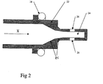
- Fig. 2 shows the sectional view of a sensor housing 22, in which the Assembly according to FIG. 1 is used.
- the sensor housing 22 has an opening 24, in which the assembly of FIG. 1, consisting from the holding elements 4 and 6 of the intermediate membrane 2, and the sealing members 12, 14, in a direction parallel to the surface the membrane 2 is inserted. Laterally are in the opening 24 Terminal holes 26 are formed, which are substantially normal to the longitudinal axis of the opening 24 and to the insertion direction X of the module extend according to FIG. 1.
- Terminal holes 26 are formed, which are substantially normal to the longitudinal axis of the opening 24 and to the insertion direction X of the module extend according to FIG. 1.
- connection holes 26 are with appropriate connection cables or with the Environment connected to the membrane 2 with desired pressures to impose which are to be recorded.
- a further sealing ring 28 is arranged to the housing 22nd when it is in a plant or device in which a Pressure is to be determined, is used.
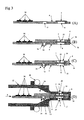
- Fig. 3 shows stepwise the assembly of the invention Pressure sensor.
- a circuit board 4 is shown, which simultaneously acts as the first holding element.
- electronic Components 30 for forwarding and / or further processing of a Measuring signal arranged in a known manner.
- a through hole 8 is formed. Over the through hole 8 is the membrane 2 is placed on the board. The through hole 8 serves later to pressurize the membrane 2.
- the at the Membrane 2 arranged measuring elements (not shown here) be electrically with formed on the board 4 conductor tracks connected. This is done by that arranged on the membrane 2 Tracks or contacts with corresponding contact points the surface of the board 4 come into contact.
- another through hole 32 is provided to a locking element for Record connection of the board 4 with a second holding element 6 to be able to.
- the illustration (B) shows the second step of assembling the inventive sensor.
- the holding element 6 On the board 4 with arranged on this Membrane 2, the holding element 6 is placed. there the retaining element 6 comes flat on the board 4 and the first holding element 4 to lie.
- the membrane 2 is in a recess 18 received on the holding element 6, so that the holding elements. 4 and 6 can lie flush with each other with their surfaces.
- the formed in the second holding member 6 through hole 10th comes substantially in alignment over the through hole 8 in the Board 4 to lie. So later, the membrane 2 on the two Through holes 8 and 10 are pressurized from both sides be used to determine a differential pressure between both sides.
- the holding element 6 has a plate 4 facing the locking projection 34, which in the through hole 32 in the board 4th engages and so the retaining element 6 is locked to the board 4. additionally Alternatively, the holding elements 4 and 6, for example, with each other glued or riveted. In a preferred embodiment are the holding member 6 and the board 4 in one piece, preferably made of plastic. This can be done on the side edge 36 formed between the board 4 and the support member 6, a film hinge be, which connects the board 4 with the support member 6. In the production then the holding element 6 and the board 4 injected or molded as a one-piece strip. For mounting will then the holding element 6 folded around the hinge on the side edge 36, so as to be on the board 4 as shown in Fig. 3 (B) comes and locked on the locking projection 34 with the board 4.
- sealing rings become 12 and 14 in the through holes 8 and 10 in the board 4 and the retaining element 6 inserted from the outside.
- the through holes 8 and 10 are in their dimension with the sealing rings to be used 12 and 14 preferably coordinated so that the sealing rings 12, 14 each have an outer circumference or diameter, which with the inner cross section of the associated through hole corresponds.
- the sealing rings 12 and 14 on the membrane 2 in the directions parallel to the membrane surfaces be positioned and fixed.
- the sealing rings 12 and 14 each have a thickness which is greater than the thickness of the associated Board 4 and the associated holding element 6 in the region of Through hole 8 and the through hole 10 is. In this way is achieved that the sealing ring 14 on the outer surface of the holding element 6 projects and that the sealing ring 12 on the outer surface of the board 4 protrudes outward.
- Fig. 3 (D) shows the state in which the preassembled module according to Fig. 3 (C) inserted or inserted into a sensor housing according to FIG is.
- the housing 22 may be integrally formed and has an opening 24.
- this opening 24 is in the direction of arrow X, d. H. in a direction parallel to the surface of the membrane 2, the assembly as shown in FIG. 3 (C), consisting of the two holding elements. 4 and 6, the membrane 2 and the sealing elements 12 used and 14, inserted into the opening 24.
- the sealing elements 12 and 14 which over the surfaces of the board 4th and the retaining element 6 protrude outward, with the inner walls the opening 24 sealing to the plant.
- the board 4 with the holding element 6 is as far into the opening 24 inserted, that the through holes 8 and 10 in alignment are arranged to the connection holes 26 in the housing 22.
- the sealing elements 12 and 14 come in the peripheral region of the connection holes 26 on the inner wall of the opening 24 to the plant. Consequently becomes a sealed passage from the terminal holes 26 to the two opposite membrane surfaces of the Membrane 2 created.
- the membrane 2 of two Pages via the connection holes 26 are pressurized to a pressure difference between both sides due to the occurring Deflection of the membrane to determine.
- the mounted in this way Sensor can be used in a device in which to determine a pressure is.
- Fig. 4 shows a schematic sectional view of the end portion of the board 4 with the attached membrane 2.
- the membrane 2 has, as in the European Patent Application EP 97 105 396.2 described in their Center on a tapered portion 38, which is the actual membrane forms, which is deflected to determine the pressure.
- the peripheral area of the thinned portion 38 functions as Carrier.
- the membrane 2 is above the through hole 8 in the board 4 arranged so that the tapered portion 38 as centrally as possible the through hole 8 is arranged.
- the electrical or electronic Components for determining the deflection of the membrane 2 and the tapered portion 38 of the membrane 2, on the membrane 2 are arranged with the board 4 via contact points 40 and 42 electrically connected.
- Fig. 5 shows a plan view of the board 4 with the membrane 2 according to Fig. 4.
- the line A-A in Fig. 5 the cutting line, along of which the section of FIG. 4 runs.
- the schematic illustration 5 are also in the view actually below the Membrane 2 located elements shown.
- So is in the through hole 8 arranged in the board 4 of the sealing ring 12 in the form of an O-ring.
- Surrounding the through hole 8 are at four evenly spaced points the contact points 42, which with corresponding, opposite contact points 40th on the membrane 2 are in contact.
- the connection of the contact points 40 and 42 with each other for example, in a known manner Soldering or bonding.
- the membrane 2 to connect to the board 4 by means of an adhesive 43.
- the adhesive 43 is preferably chosen so that it hardens shrinking. If such an adhesive 43 in the region of the contact points 40, 42, causes the shrinkage of the adhesive 43 during curing, that the contact points 40 and 42 pulled towards each other will come into contact and contact each other. At the same time, the surrounding adhesive 43 forms a protective layer.
- the Contact pads 40 and 42 are normal to the surface of the board a height such that the membrane 2 spaced from the Board 4 is arranged. This creates between the contact points located column 44, which the venting of the through hole. 8 serve.
- the gaps extend from the rear space of the Seal member 12 in the through hole 8 to the outer periphery This has the advantage that a fluid, in particular Moisture, which passes through the sealing member 12, from the rear space between the sealing element 12 and the inner wall of the through hole 8 can escape to the outside.
- the holding element 4, 6 with a connection channel be provided.
- FIGS. 2 and 3 show various embodiments of the housing 22, wherein arranged in the interior of the housing 22 assembly consisting of board 4, retaining element 6, membrane 2 and sealing elements 12 and 14 is always identical and the basis of Figures 1 and 3 described arrangement.
- the housing 22 according to FIG. 6 substantially corresponds to that of FIGS. 2 and 3 (D). explained construction of the housing.
- In the housing are two connection holes 26 formed with the through holes 8 and 10 in the board 4 and the holding element 6 for pressurizing the Membrane 2 are in communication.
- a connection hole 26 in communication with a channel 46, which extends into the rear space of the housing 22, in the also the connection lines 16 are for the pressure sensor.
- This Area is the area of the housing 22 which is one to be measured Fluid is averted.
- the channel 46 thus stands with the ambient air on the outside of the sensor in conjunction. This allows a Pressure of entering the channel 48 fluid relative to the ambient pressure to determine.
- the channel 48 is in communication with the second connection opening 26, so that the membrane 2 through the channel 48 is pressurized by a fluid with pressure.
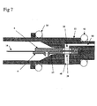
- Fig. 7 shows another embodiment of the housing 22. Also in this Housing there is a channel 48 through which the membrane. 2 can be acted upon by a pressure of a fluid.
- This Channel 48 opens on the outside of the housing 22.
- the housing 22 As shown in FIG. 7 has a second sealing ring 52 on its outside on.
- the channel 48 opens into the space between the two sealing rings 28 and 52 and can in this way with a first fluid channel keep in touch.
- This channel 50 also opens to the outside of the housing 22 in an area which through the sealing ring 52 from the area into which the channel 48 opens, is separated. In this way it is possible to have a differential pressure between channels 48 and 50, with channels 48 and 50 each may communicate with a fluid conduit. On This way, a pressure difference between two lines can be determined become.
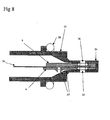
- Fig. 8 shows a third embodiment of the housing 22.
- this embodiment extend the connection holes 26, starting from the membrane 2, in extension of the through holes 8 and 10 in the Board 4 and the support member 6 normal to the outside of the housing 22 to the outside.
- the area of the housing 22 in which the membrane is arranged is formed as a tapered projection 54, to whose two opposite sides in each case a connection hole 26 opens.
- the thus configured housing 22 can be inserted into a fluid channel be sealed by the seal 28 to the outside becomes.
- the projection 54 projects into the fluid flow and can in this way detect pressure differences within the fluid flow.
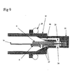
- FIG. 9 shows a fourth preferred embodiment of the housing 22.
- This embodiment corresponds essentially to the reference to FIG. 6 described embodiment, however, is the fluid wetted portion the housing in which the membrane is arranged, similar narrow as the projection 54 formed in Fig. 8.
- the projection thus formed 56 can also be used in a flow in order to determine there a pressure.
- This opens a connection opening 26 to the outside of the projection 56, d. H. in the fluid flow, while the second port opening 26 via the channel 46 communicates with the environment.
Landscapes
- Physics & Mathematics (AREA)
- General Physics & Mathematics (AREA)
- Chemical & Material Sciences (AREA)
- Analytical Chemistry (AREA)
- Measuring Fluid Pressure (AREA)
Abstract
Description
Claims (14)
- Drucksensor mit einer Membran (2) und mindestens einem auf der Membran (2) angeordneten Messelement zum Erfassen einer Membranauslenkung, gekennzeichnet durch zumindest ein an einer Oberfläche der Membran (2) zur Aufnahme eines Dichtungselementes (12) angeordnetes Halteelement (4) mit einem der Membranoberfläche zugewandten Durchgangsloch (8), das einen Querschnitt korrespondierend zur Außenkontur eines aufzunehmenden Dichtungselementes (12) aufweist
- Drucksensor nach Anspruch 1, dadurch gekennzeichnet, dass an jeder der zwei einander entgegengesetzten Oberflächen der Membran (2) jeweils ein Halteelement (4, 6) angeordnet ist mit jeweils einem der Membranoberfläche zugewandten Durchgangsloch (8, 10), das einen Querschnitt korrespondierend zur Außenkontur eines aufzunehmenden Dichtungselementes (12, 14) aufweist.
- Drucksensor nach Anspruch 1 oder 2, dadurch gekennzeichnet, dass die Halteelemente (4, 5) im Bereich des Durchgangslochs (8, 10) eine Stärke geringer als die Dicke eines einzusetzenden Dichtungselementes (12, 14) aufweisen.
- Drucksensor nach einem der vorangehenden Ansprüche, dadurch gekennzeichnet, dass das Dichtungselement (12, 14) ein Dichtungsring und insbesondere ein O-Ring ist.
- Drucksensor nach einem der vorangehenden Ansprüche, dadurch gekennzeichnet, dass das Dichtungselement (12, 14) fest mit dem Halteelement (4, 6) verbunden und insbesondere einstückig mit diesem ausgebildet ist.
- Drucksensor nach einem der Ansprüche 2 bis 5, dadurch gekennzeichnet, dass die beiden Halteelemente (4, 6) über zumindest eine Rastverbindung (20) miteinander verbunden sind.
- Drucksensor nach einem der Ansprüche 2 bis 6, dadurch gekennzeichnet, dass die beiden Halteelemente (4, 6) einstückig ausgebildet und über ein Scharnier miteinander verbunden sind.
- Drucksensor nach einem der vorangehenden Ansprüche, dadurch gekennzeichnet, dass in zumindest einem Halteelement (6) an einer Oberfläche ein das Durchgangsloch (10) umgebender Absatz (18) zur Aufnahme der Membran (2) ausgebildet ist.
- Drucksensor nach einem der vorangehenden Ansprüche, dadurch gekennzeichnet, dass zumindest ein Halteelement (4) von einer Platine gebildet wird.
- Drucksensor nach Anspruch 9, dadurch gekennzeichnet, dass die Membran (2) mit auf der Platine (4) ausgebildeten Leiterbahnen über im Umfangsbereich des Durchgangsloches (8) angeordnete Kontaktstellen (40, 42) elektrisch verbunden ist.
- Drucksensor nach Anspruch 10, dadurch gekennzeichnet, dass zwischen den Kontaktstellen (40, 42) zwischen Membran (2) und Platine (4) sich, vorzugsweise parallel zur Membranoberfläche, von dem Durchgangsloch (8) zum Außenumfang der Membran (2) erstreckende Spalte (44) ausgebildet sind.
- Drucksensor nach einem der vorangehenden Ansprüche, dadurch gekennzeichnet, dass ein Sensorgehäuse (22) vorgesehen ist, in welches die Membran (2) mit dem Halteelement (4, 6) in einer Richtung parallel zur Membranoberfläche derart eingesetzt ist, dass ein in das Durchgangsloch (8, 10) des Halteelementes eingesetztes Dichtungselement (12, 14) zwischen einer Membranoberfläche und dem Sensorgehäuse (22) zur Anlage kommt.
- Drucksensor nach Anspruch 12, dadurch gekennzeichnet, dass in dem Sensorgehäuse (22) zwei Anschlusslöcher (26) angeordnet sind, welche jeweils gegenüberliegend zu einem der Durchgangslöcher (8, 10) in den Halteelementen (4, 6) münden, wobei in die Durchgangslöcher (8, 10) eingesetzte Dichtungselemente (12, 14) am Umfang der Mündung der Anschlusslöcher (26) an dem Sensorgehäuse (22) zur Anlage kommen.
- Drucksensor nach Anspruch 12 oder 13, dadurch gekennzeichnet, dass zumindest der fluidberührte Teil des Sensorgehäuses (22) einstückig ausgebildet ist.
Priority Applications (6)
| Application Number | Priority Date | Filing Date | Title |
|---|---|---|---|
| EP02008386A EP1353160B1 (de) | 2002-04-12 | 2002-04-12 | Drucksensor |
| DE50212957T DE50212957D1 (de) | 2002-04-12 | 2002-04-12 | Drucksensor |
| US10/511,002 US7143650B2 (en) | 2002-04-12 | 2003-04-08 | Pressure sensor |
| CNB038082918A CN100339692C (zh) | 2002-04-12 | 2003-04-08 | 压力传感器 |
| PCT/EP2003/003630 WO2003087752A1 (de) | 2002-04-12 | 2003-04-08 | Drucksensor |
| AU2003229624A AU2003229624A1 (en) | 2002-04-12 | 2003-04-08 | Pressure sensor |
Applications Claiming Priority (1)
| Application Number | Priority Date | Filing Date | Title |
|---|---|---|---|
| EP02008386A EP1353160B1 (de) | 2002-04-12 | 2002-04-12 | Drucksensor |
Publications (2)
| Publication Number | Publication Date |
|---|---|
| EP1353160A1 true EP1353160A1 (de) | 2003-10-15 |
| EP1353160B1 EP1353160B1 (de) | 2008-10-29 |
Family
ID=28051788
Family Applications (1)
| Application Number | Title | Priority Date | Filing Date |
|---|---|---|---|
| EP02008386A Expired - Lifetime EP1353160B1 (de) | 2002-04-12 | 2002-04-12 | Drucksensor |
Country Status (6)
| Country | Link |
|---|---|
| US (1) | US7143650B2 (de) |
| EP (1) | EP1353160B1 (de) |
| CN (1) | CN100339692C (de) |
| AU (1) | AU2003229624A1 (de) |
| DE (1) | DE50212957D1 (de) |
| WO (1) | WO2003087752A1 (de) |
Cited By (5)
| Publication number | Priority date | Publication date | Assignee | Title |
|---|---|---|---|---|
| US7013738B2 (en) | 2002-12-24 | 2006-03-21 | Grundfos A/S | Flow sensor |
| EP1698877A1 (de) | 2005-03-05 | 2006-09-06 | Grundfos Management A/S | Differenzdrucksensor-Anordnung und zugehöriger Differenzdrucksensor |
| DE102008026020A1 (de) * | 2008-05-30 | 2009-12-17 | Ifm Electronic Gmbh | Drucksensor für Pneumatikapplikationen |
| EP2096423A3 (de) * | 2008-02-29 | 2013-10-16 | Robert Bosch Gmbh | Sensoranordnung |
| US20140161639A1 (en) * | 2012-12-11 | 2014-06-12 | Dab Pumps S.P.A. | Pressure transducer |
Families Citing this family (5)
| Publication number | Priority date | Publication date | Assignee | Title |
|---|---|---|---|---|
| JP4379360B2 (ja) * | 2005-03-22 | 2009-12-09 | 株式会社日立製作所 | 力学量測定装置 |
| DE102006059392A1 (de) * | 2006-12-08 | 2008-06-12 | Würth Elektronik Pforzheim GmbH & Co. KG | Leiterplatte |
| JP6034818B2 (ja) * | 2014-03-04 | 2016-11-30 | アズビル株式会社 | 圧力センサチップ |
| CN109100277B (zh) * | 2018-06-04 | 2024-09-13 | 上海交通大学 | 一种过滤网寿命测试系统及其测试方法 |
| FR3101416B1 (fr) * | 2019-09-26 | 2021-12-24 | Ateq | Capteur de pression différentielle et dispositif de détection comprenant un tel capteur |
Citations (4)
| Publication number | Priority date | Publication date | Assignee | Title |
|---|---|---|---|---|
| EP0687895A2 (de) * | 1994-06-17 | 1995-12-20 | Instrumentarium Corporation | Verfahren und Vorrichtung zum Einspannen einer Membran |
| GB2308447A (en) * | 1995-12-22 | 1997-06-25 | Ultra Hydraulics Ltd | Pressure sensing device |
| US6311561B1 (en) * | 1997-12-22 | 2001-11-06 | Rosemount Aerospace Inc. | Media compatible pressure sensor |
| JP2002005771A (ja) * | 2000-06-26 | 2002-01-09 | Nippon Flow Cell Kk | 変動圧力センサ |
Family Cites Families (2)
| Publication number | Priority date | Publication date | Assignee | Title |
|---|---|---|---|---|
| NL7415668A (nl) * | 1974-12-02 | 1976-06-04 | Philips Nv | Drukopnemer. |
| JPS6227637A (ja) * | 1985-07-29 | 1987-02-05 | Chino Corp | 圧力センサ |
-
2002
- 2002-04-12 DE DE50212957T patent/DE50212957D1/de not_active Expired - Lifetime
- 2002-04-12 EP EP02008386A patent/EP1353160B1/de not_active Expired - Lifetime
-
2003
- 2003-04-08 WO PCT/EP2003/003630 patent/WO2003087752A1/de not_active Ceased
- 2003-04-08 CN CNB038082918A patent/CN100339692C/zh not_active Expired - Lifetime
- 2003-04-08 US US10/511,002 patent/US7143650B2/en not_active Expired - Lifetime
- 2003-04-08 AU AU2003229624A patent/AU2003229624A1/en not_active Abandoned
Patent Citations (4)
| Publication number | Priority date | Publication date | Assignee | Title |
|---|---|---|---|---|
| EP0687895A2 (de) * | 1994-06-17 | 1995-12-20 | Instrumentarium Corporation | Verfahren und Vorrichtung zum Einspannen einer Membran |
| GB2308447A (en) * | 1995-12-22 | 1997-06-25 | Ultra Hydraulics Ltd | Pressure sensing device |
| US6311561B1 (en) * | 1997-12-22 | 2001-11-06 | Rosemount Aerospace Inc. | Media compatible pressure sensor |
| JP2002005771A (ja) * | 2000-06-26 | 2002-01-09 | Nippon Flow Cell Kk | 変動圧力センサ |
Non-Patent Citations (1)
| Title |
|---|
| PATENT ABSTRACTS OF JAPAN vol. 2002, no. 05 3 May 2002 (2002-05-03) * |
Cited By (9)
| Publication number | Priority date | Publication date | Assignee | Title |
|---|---|---|---|---|
| US7013738B2 (en) | 2002-12-24 | 2006-03-21 | Grundfos A/S | Flow sensor |
| EP1698877A1 (de) | 2005-03-05 | 2006-09-06 | Grundfos Management A/S | Differenzdrucksensor-Anordnung und zugehöriger Differenzdrucksensor |
| WO2006094692A1 (de) * | 2005-03-05 | 2006-09-14 | Grundfos Management A/S | Differenzdrucksensor-anordnung und zugehöriger differenzdrucksensor |
| US7607354B2 (en) | 2005-03-05 | 2009-10-27 | Grundfos Management A/S | Differential pressure sensor arrangement and associated differential pressure sensor |
| EP2096423A3 (de) * | 2008-02-29 | 2013-10-16 | Robert Bosch Gmbh | Sensoranordnung |
| DE102008026020A1 (de) * | 2008-05-30 | 2009-12-17 | Ifm Electronic Gmbh | Drucksensor für Pneumatikapplikationen |
| DE102008026020B4 (de) * | 2008-05-30 | 2013-04-11 | Ifm Electronic Gmbh | Druckmessgerät zur Differenzdruckmessung |
| US20140161639A1 (en) * | 2012-12-11 | 2014-06-12 | Dab Pumps S.P.A. | Pressure transducer |
| EP2743666A1 (de) * | 2012-12-11 | 2014-06-18 | Dab Pumps S.p.A. | Gehäusezusammenbau für Drucksensor |
Also Published As
| Publication number | Publication date |
|---|---|
| EP1353160B1 (de) | 2008-10-29 |
| CN1646889A (zh) | 2005-07-27 |
| CN100339692C (zh) | 2007-09-26 |
| US20050235752A1 (en) | 2005-10-27 |
| WO2003087752A1 (de) | 2003-10-23 |
| DE50212957D1 (de) | 2008-12-11 |
| US7143650B2 (en) | 2006-12-05 |
| AU2003229624A1 (en) | 2003-10-27 |
Similar Documents
| Publication | Publication Date | Title |
|---|---|---|
| EP1989523B1 (de) | Verfahren zum herstellen einer fluiddruckmesseinheit und komponente zum einsatz in einer fluiddruckmesseinheit | |
| EP1099066B1 (de) | Steuergerät in einem kraftfahrzeug und verfahren zum befestigen eines von diesem verwendeten drucksensors | |
| EP2167930B1 (de) | Anschlusseinheit für eine druckmesszelle | |
| EP0927344B1 (de) | Drucksensoreinheit, insbesondere für die kraftfahrzeugtechnik | |
| DE19703206A1 (de) | Drucksensor-Bauteil mit Schlauchanschluß | |
| EP2025213B1 (de) | Sensorbaugruppe mit einem an einer wand montierbaren gehäuse | |
| EP0935743B1 (de) | Drucksensoreinheit, insbesondere für die kraftfahrzeugtechnik | |
| EP2180951B1 (de) | Durchflusssensor und herstellungsverfahren dafür | |
| EP0829003B1 (de) | Drucksensor und verfahren zur herstellung eines drucksensors | |
| DE102006043884A1 (de) | Halbleiterdrucksensor und Stempel zum Formen des Sensors | |
| EP1353160B1 (de) | Drucksensor | |
| EP1698877B1 (de) | Differenzdrucksensor-Anordnung und zugehöriger Differenzdrucksensor | |
| EP0695934B1 (de) | Verbindungsvorrichtung für ein Manometer und Verfahren zu seiner Herstellung | |
| DE102021204971A1 (de) | Adaptionseinrichtung zur Ankopplung mindestens eines Sensors an eine Schlauchmantelwand eines Schlauchs zur Fluidvermessung sowie Sensorvorrichtung mit einer derartigen Adaptionseinrichtung | |
| EP4246113B1 (de) | Modular aufgebauter differenzdrucksensor | |
| WO2008148652A2 (de) | Schnell montierbares sensorgehäuse für sensoren mit luftkontakt | |
| EP1534055B1 (de) | Gehaüse für ein elektrisches Bauteil | |
| DE10059813A1 (de) | Vorrichtung zur Erfassung eines Fluiddrucks | |
| DE102023209056A1 (de) | Drucksensor zur Erfassung des Drucks eines Messmediums und Dichtungselement für einen solchen Drucksensor | |
| DE102022214062A1 (de) | Verbindungsanordnung zwischen zwei Gehäusekammern | |
| DE202005011253U1 (de) | 3-D-Drucksensor | |
| DE4105676C1 (en) | Electrostatic pump or flow velocity sensor - has seal around flow aperture mounted on surface of semiconductor device | |
| DE102024004539A1 (de) | Einhausung, Bauteilanordnung, Sensoranordnung, Drucksensoranordnung und Gassensoranordnung | |
| DE102020202454A1 (de) | Drucksensor zur Erfassung eines Drucks eines fluiden Mediums und Verfahren zur Herstellung eines solchen Drucksensors | |
| DE102024122416A1 (de) | Einhausung, Bauteilanordnung, Sensoranordnung, Drucksensoranordnung und Gassensoranordnung |
Legal Events
| Date | Code | Title | Description |
|---|---|---|---|
| PUAI | Public reference made under article 153(3) epc to a published international application that has entered the european phase |
Free format text: ORIGINAL CODE: 0009012 |
|
| AK | Designated contracting states |
Kind code of ref document: A1 Designated state(s): AT BE CH CY DE DK ES FI FR GB GR IE IT LI LU MC NL PT SE TR |
|
| AX | Request for extension of the european patent |
Extension state: AL LT LV MK RO SI |
|
| 17P | Request for examination filed |
Effective date: 20031121 |
|
| AKX | Designation fees paid |
Designated state(s): DE FR GB IT |
|
| GRAP | Despatch of communication of intention to grant a patent |
Free format text: ORIGINAL CODE: EPIDOSNIGR1 |
|
| GRAS | Grant fee paid |
Free format text: ORIGINAL CODE: EPIDOSNIGR3 |
|
| GRAA | (expected) grant |
Free format text: ORIGINAL CODE: 0009210 |
|
| AK | Designated contracting states |
Kind code of ref document: B1 Designated state(s): DE FR GB IT |
|
| REG | Reference to a national code |
Ref country code: GB Ref legal event code: FG4D Free format text: NOT ENGLISH |
|
| REF | Corresponds to: |
Ref document number: 50212957 Country of ref document: DE Date of ref document: 20081211 Kind code of ref document: P |
|
| PLBE | No opposition filed within time limit |
Free format text: ORIGINAL CODE: 0009261 |
|
| STAA | Information on the status of an ep patent application or granted ep patent |
Free format text: STATUS: NO OPPOSITION FILED WITHIN TIME LIMIT |
|
| 26N | No opposition filed |
Effective date: 20090730 |
|
| REG | Reference to a national code |
Ref country code: FR Ref legal event code: PLFP Year of fee payment: 15 |
|
| REG | Reference to a national code |
Ref country code: FR Ref legal event code: PLFP Year of fee payment: 16 |
|
| REG | Reference to a national code |
Ref country code: FR Ref legal event code: PLFP Year of fee payment: 17 |
|
| PGFP | Annual fee paid to national office [announced via postgrant information from national office to epo] |
Ref country code: DE Payment date: 20200423 Year of fee payment: 19 Ref country code: FR Payment date: 20200421 Year of fee payment: 19 |
|
| PGFP | Annual fee paid to national office [announced via postgrant information from national office to epo] |
Ref country code: GB Payment date: 20200423 Year of fee payment: 19 Ref country code: IT Payment date: 20200423 Year of fee payment: 19 |
|
| REG | Reference to a national code |
Ref country code: DE Ref legal event code: R119 Ref document number: 50212957 Country of ref document: DE |
|
| GBPC | Gb: european patent ceased through non-payment of renewal fee |
Effective date: 20210412 |
|
| PG25 | Lapsed in a contracting state [announced via postgrant information from national office to epo] |
Ref country code: GB Free format text: LAPSE BECAUSE OF NON-PAYMENT OF DUE FEES Effective date: 20210412 Ref country code: FR Free format text: LAPSE BECAUSE OF NON-PAYMENT OF DUE FEES Effective date: 20210430 Ref country code: DE Free format text: LAPSE BECAUSE OF NON-PAYMENT OF DUE FEES Effective date: 20211103 |
|
| PG25 | Lapsed in a contracting state [announced via postgrant information from national office to epo] |
Ref country code: IT Free format text: LAPSE BECAUSE OF NON-PAYMENT OF DUE FEES Effective date: 20200412 |
|
| PG25 | Lapsed in a contracting state [announced via postgrant information from national office to epo] |
Ref country code: IT Free format text: LAPSE BECAUSE OF NON-PAYMENT OF DUE FEES Effective date: 20210412 |