EP1353042B1 - A gas turbine single plant modifying method, a catalyst re-using method and a re-produced catalyst - Google Patents
A gas turbine single plant modifying method, a catalyst re-using method and a re-produced catalyst Download PDFInfo
- Publication number
- EP1353042B1 EP1353042B1 EP03006094A EP03006094A EP1353042B1 EP 1353042 B1 EP1353042 B1 EP 1353042B1 EP 03006094 A EP03006094 A EP 03006094A EP 03006094 A EP03006094 A EP 03006094A EP 1353042 B1 EP1353042 B1 EP 1353042B1
- Authority
- EP
- European Patent Office
- Prior art keywords
- catalyst
- denitration catalyst
- temperature denitration
- high temperature
- produced
- Prior art date
- Legal status (The legal status is an assumption and is not a legal conclusion. Google has not performed a legal analysis and makes no representation as to the accuracy of the status listed.)
- Expired - Fee Related
Links
Images

Classifications
-
- B—PERFORMING OPERATIONS; TRANSPORTING
- B01—PHYSICAL OR CHEMICAL PROCESSES OR APPARATUS IN GENERAL
- B01J—CHEMICAL OR PHYSICAL PROCESSES, e.g. CATALYSIS OR COLLOID CHEMISTRY; THEIR RELEVANT APPARATUS
- B01J23/00—Catalysts comprising metals or metal oxides or hydroxides, not provided for in group B01J21/00
- B01J23/90—Regeneration or reactivation
- B01J23/92—Regeneration or reactivation of catalysts comprising metals, oxides or hydroxides provided for in groups B01J23/02 - B01J23/36
-
- B—PERFORMING OPERATIONS; TRANSPORTING
- B01—PHYSICAL OR CHEMICAL PROCESSES OR APPARATUS IN GENERAL
- B01D—SEPARATION
- B01D53/00—Separation of gases or vapours; Recovering vapours of volatile solvents from gases; Chemical or biological purification of waste gases, e.g. engine exhaust gases, smoke, fumes, flue gases, aerosols
- B01D53/34—Chemical or biological purification of waste gases
- B01D53/74—General processes for purification of waste gases; Apparatus or devices specially adapted therefor
- B01D53/86—Catalytic processes
- B01D53/8621—Removing nitrogen compounds
- B01D53/8625—Nitrogen oxides
- B01D53/8628—Processes characterised by a specific catalyst
-
- B—PERFORMING OPERATIONS; TRANSPORTING
- B01—PHYSICAL OR CHEMICAL PROCESSES OR APPARATUS IN GENERAL
- B01D—SEPARATION
- B01D53/00—Separation of gases or vapours; Recovering vapours of volatile solvents from gases; Chemical or biological purification of waste gases, e.g. engine exhaust gases, smoke, fumes, flue gases, aerosols
- B01D53/34—Chemical or biological purification of waste gases
- B01D53/96—Regeneration, reactivation or recycling of reactants
-
- B—PERFORMING OPERATIONS; TRANSPORTING
- B01—PHYSICAL OR CHEMICAL PROCESSES OR APPARATUS IN GENERAL
- B01J—CHEMICAL OR PHYSICAL PROCESSES, e.g. CATALYSIS OR COLLOID CHEMISTRY; THEIR RELEVANT APPARATUS
- B01J38/00—Regeneration or reactivation of catalysts, in general
- B01J38/48—Liquid treating or treating in liquid phase, e.g. dissolved or suspended
- B01J38/485—Impregnating or reimpregnating with, or deposition of metal compounds or catalytically active elements
-
- F—MECHANICAL ENGINEERING; LIGHTING; HEATING; WEAPONS; BLASTING
- F01—MACHINES OR ENGINES IN GENERAL; ENGINE PLANTS IN GENERAL; STEAM ENGINES
- F01K—STEAM ENGINE PLANTS; STEAM ACCUMULATORS; ENGINE PLANTS NOT OTHERWISE PROVIDED FOR; ENGINES USING SPECIAL WORKING FLUIDS OR CYCLES
- F01K23/00—Plants characterised by more than one engine delivering power external to the plant, the engines being driven by different fluids
- F01K23/02—Plants characterised by more than one engine delivering power external to the plant, the engines being driven by different fluids the engine cycles being thermally coupled
- F01K23/06—Plants characterised by more than one engine delivering power external to the plant, the engines being driven by different fluids the engine cycles being thermally coupled combustion heat from one cycle heating the fluid in another cycle
- F01K23/10—Plants characterised by more than one engine delivering power external to the plant, the engines being driven by different fluids the engine cycles being thermally coupled combustion heat from one cycle heating the fluid in another cycle with exhaust fluid of one cycle heating the fluid in another cycle
-
- Y—GENERAL TAGGING OF NEW TECHNOLOGICAL DEVELOPMENTS; GENERAL TAGGING OF CROSS-SECTIONAL TECHNOLOGIES SPANNING OVER SEVERAL SECTIONS OF THE IPC; TECHNICAL SUBJECTS COVERED BY FORMER USPC CROSS-REFERENCE ART COLLECTIONS [XRACs] AND DIGESTS
- Y02—TECHNOLOGIES OR APPLICATIONS FOR MITIGATION OR ADAPTATION AGAINST CLIMATE CHANGE
- Y02E—REDUCTION OF GREENHOUSE GAS [GHG] EMISSIONS, RELATED TO ENERGY GENERATION, TRANSMISSION OR DISTRIBUTION
- Y02E20/00—Combustion technologies with mitigation potential
- Y02E20/16—Combined cycle power plant [CCPP], or combined cycle gas turbine [CCGT]
Definitions
- the present invention relates to a method for modifying a gas turbine single plant into a combined cycle plant comprising a combination of this gas turbine, a waste heat recovery boiler and a steam turbine and a method for re-using a used high temperature denitration catalyst of the gas turbine single plant as an intermediate temperature denitration catalyst of other modified, existing or new plants and also relates to a re-produced catalyst.
- gas turbine single plants that are excellent in the operability and constructible with less investment cost and shorter period
- the gas turbine single plant is less excellent in the long term plant efficiency and hence it is effective that a gas turbine single plant is first constructed to be modified in the future by re-powering work into a combined cycle plant that is excellent in the plant efficiency.
- a catalyst that contains TiO 2 (titanium oxide) as a main component and includes at least one of WO 3 (tungsten oxide) and MoO 3 (molybdenum oxide) and further includes V 2 O 5 (vanadium oxide).
- the denitration catalyst containing the minute amount or none of V 2 O 5 component is a catalyst that is optimized for the high temperature.
- this high temperature denitration catalyst cannot be used for the combined cycle plant in which the temperature of the exhaust gas to be denitrified is an intermediate temperature of 200 to 450°C.
- Patent Document 1
- Patent Document 2
- Patent Document 3
- Patent Document 4
- the present invention provides a method for modifying a gas turbine single plant into a combined cycle plant by which, in modifying the gas turbine single plant into a combined cycle plant, a used high temperature denitration catalyst is reproduced as an intermediate temperature denitration catalyst and this re-produced intermediate temperature denitration catalyst is re-used as a denitration catalyst of the combined cycle plant after modified.
- the used high temperature denitration catalyst of the gas turbine single plant is re-produced as the intermediate temperature denitration catalyst to be used for the combined cycle plant.
- the equipment cost required for the re-powering of the plant can be largely reduced.
- the used high temperature denitration catalyst is re-used, the waste cost thereof is saved and thereby a burden on the environment caused by the waste can be alleviated.
- the present invention provides a method for re-using a used high temperature denitration catalyst by which the used high temperature denitration catalyst of a gas turbine single plant is re-produced as an intermediate temperature denitration catalyst and this re-produced intermediate temperature denitration catalyst is re-used as an intermediate temperature denitration catalyst of other modified, existing or new plants.
- the used high temperature denitration catalyst in re-powering the gas turbine single plant, can be effectively re-used as an intermediate temperature denitration catalyst and thereby a re-selling business of the catalyst as an intermediate temperature denitration catalyst of modified, existing or new plants other than the mentioned gas turbine single plant can be appropriately realized corresponding to a required amount of the catalyst, a geographical position of the plant or the like.
- TiO 2 is contained as a main component and at least one of WO 3 and MoO 3 is included.
- the composition may include V 2 O 5 of 0.5 wt(weight)% or less, preferably 0.2 wt% or less, or may include none of V 2 O 5 .
- the used high temperature denitration catalyst is of the abovementioned composition, the quantity of the catalyst available for re-use is large and thus the modifying or re-using method of the present invention is extremely effective.
- the present invention provides a modifying or re-using method in which the intermediate temperature denitration catalyst is re-produced by including V 2 O 5 component of 0.5 wt% or more, preferably 1.0 wt% or more, in the used high temperature denitration catalyst as well as provides a re-produced catalyst that is re-produced with the same composition included in the used high temperature denitration catalyst.
- the present invention provides a modifying and re-using method in which, where the high temperature denitration catalyst to be re-used is a catalyst that is optimized so as to be used in the temperature range up to maximum 450 to 600°C, the intermediate temperature denitration catalyst is re-produced by including V (vanadium) component in the used high temperature denitration catalyst and is optimized so as to be used in the temperature range of 200 to 450°C as well as the present invention provides a re-produced catalyst that is optimized for the same temperature range.
- V vanadium
- the present invention provides a modifying or re-using method in which the inclusion treatment of the V component is carried out by immersion into V-containing water solution and drying and/or burning as well as it provides a re-produced catalyst that is re-produced by the same treatment.
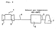
- Fig. 4 shows a gas turbine single plant in the prior art before it is modified into a combined cycle plant by applying the present invention.
- numeral 1 designates a gas turbine equipment
- numeral 2 designates a compressor
- numeral 3 designates a gas turbine.
- the construction is made such that exhaust gas of the gas turbine 3 flows through a duct 4 to be led into a denitration equipment 6 for denitration treatment therein and then further flows through a duct 5 to be emitted into the air from a stack 7.
- Temperature of the exhaust gas coming from the gas turbine 3 to be led into the denitration equipment 6 is as high as 450 to 600°C.
- a high temperature denitration catalyst is used so as to stand such a high temperature for effecting the denitration reaction.
- the denitration catalyst contains TiO 2 as a main component and an active component, such as WO 3 or MoO 3 , as the gas to be treated is of the high temperature as mentioned above, inclusion of V component in the catalyst is very small or even zero such that V 2 O 5 that is thermally vulnerable is 0.5 wt% or less, preferably 0.2 wt% or less, or no V 2 O 5 is included.
- the exhaust gas to be treated for denitration is first injected with NH 3 (ammonia) so as to be made contact with the catalyst, and by the reactions that 4NO + 4NH 3 + O 2 ⁇ 4N 2 + 6H 2 O, NO + NO 2 + 2NH 3 ⁇ 2N 2 + 3H 2 O, NO and NO 2 are decomposed into an innoxious nitrogen and water.
- NH 3 ammonia
- Fig. 1 shows a combined cycle plant modified by applying the present invention.
- numeral 9 designates an exhaust gas boiler, that uses the exhaust gas of the gas turbine equipment 1 as a heat source.
- Numeral 10 designates a steam turbine, that is operated by being supplied with steam generated at the exhaust gas boiler 9.
- temperature of the exhaust gas coming out of the exhaust gas boiler 9 is reduced to an intermediate temperature of 450 to 200°C.
- This intermediate temperature exhaust gas is applied with the denitration treatment at the denitration equipment 8 and is then emitted into the air from the stack 7.
- the intermediate temperature denitration catalyst obtained by the present invention is used.
- the intermediate temperature denitration catalyst to be used in the denitration equipment 8 is re-produced from the high temperature denitration catalyst that has been used in the denitration equipment 6 of the gas turbine single plant shown in Fig. 4.
- the high temperature denitration catalyst used in the denitration equipment 6 of Fig. 4 contains TiO 2 as a main component and an active component of WO 3 or MoO 3 or the like, but inclusion of the V component that is thermally vulnerable is very small or even zero.
- the used high temperature denitration catalyst is treated so as to contain V 2 O 5 of 0.5 wt% or more, preferably 1.0 wt% or more.
- the catalyst For treating the TiO 2 •WO 3 group high temperature denitration catalyst so as to contain V 2 O 5 , the catalyst is first immersed in an oxalic acid solution of V 2 O 5 and is then dried and/or burned. If drying only is applied, the catalyst is changed to a burned state by the exhaust gas in the actual operation.
- W1 is weight of the catalyst before immersion (kg) and W2 is weight of the catalyst after immersion (kg).
- B is the aimed V 2 O 5 concentration in the catalyst and a is the water content (liter/kg).
- Oxalic acid (H 2 C 2 O 4 ) of 2.5 Xkg is dissolved in warm water of about 0.9 liter.
- V 2 O 5 powder Xkg is gradually added into this solution to be dissolved therein and then water is added so that a solution for immersion of 1 liter is made.
- the used high temperature denitration catalyst is immersed into this immersion solution for about 1 minute. Then, this catalyst is dried and burned for 3 hours at 550°C.
- the high temperature denitration catalyst to be re-used is not necessarily a TiO 2 •WO 3 group catalyst.
- composition ratio of the high temperature denitration catalyst has been taken from a basic framework that TiO 2 is 60 to 80 wt%, WO 3 (MoO 3 ) is 5 to 25 wt% and V 2 O 5 is 0 to 10 wt%, wherein MoO 3 is the alternative for W03, the composition ratio may be optimized according to fuel for combustion, temperature of the gas to be treated, etc.
- the procedure of treatment to give V component to the catalyst is not limited to the use of the oxalic acid solution but, for example, citric acid water solution, methylamine water solution of ammonium metavanadic acid, sulfamic acid water solution, etc. may be used as wash medium.
- the construction shown in Fig. 2 in which the denitration equipment 8 is interposed between an exhaust gas boiler 9-1 and an exhaust gas boiler 9-2 is made such that, in the gas turbine single plant, spaces are left beforehand upstream and downstream of the denitration equipment 8 and the two exhaust gas boilers 9-1, 9-2 are added on both sides of the denitration equipment 8 later in the modification to the combined cycle plant.
- the cost for modification to the combined cycle plant becomes higher than the construction shown in Fig. 1, a larger waste heat recovery can be realized and a further enhanced efficiency can be expected in the plant operation.
- the construction shown in Fig. 3 in which the denitration equipment 8 is assembled into the exhaust gas boiler 9 is made such that the denitration equipment 8 is structured beforehand so as to be assembled into the exhaust gas boiler and the denitration equipment 8 is so assembled later in the modification to the combined cycle plant.
- the equipment structure and the modification work become somewhat complicated, the high efficiency in the plant operation is expected similarly to the construction shown in Fig. 2, the installation space is reduced and a compact sized plant can be realized.
Description
- The present invention relates to a method for modifying a gas turbine single plant into a combined cycle plant comprising a combination of this gas turbine, a waste heat recovery boiler and a steam turbine and a method for re-using a used high temperature denitration catalyst of the gas turbine single plant as an intermediate temperature denitration catalyst of other modified, existing or new plants and also relates to a re-produced catalyst.
- Recently, in order to cope with an urgent demand for electric power, there are often constructed gas turbine single plants that are excellent in the operability and constructible with less investment cost and shorter period, However, the gas turbine single plant is less excellent in the long term plant efficiency and hence it is effective that a gas turbine single plant is first constructed to be modified in the future by re-powering work into a combined cycle plant that is excellent in the plant efficiency.
- On the other hand, in a denitration equipment that is installed for denitration of the exhaust gas in a power plant or the like, there is used a catalyst that contains TiO2 (titanium oxide) as a main component and includes at least one of WO3 (tungsten oxide) and MoO3 (molybdenum oxide) and further includes V2O5 (vanadium oxide).
- In the gas turbine single plant, as the temperature of the exhaust gas to be denitrified is as high as 450 to 600°C, a high temperature denitration catalyst is used. In the high temperature denitration catalyst, V2O5 that is vulnerable in the high temperature is used only in a minute amount or no V2O5 is included. (See
Patent Document 2 below, for example.) - That is, the denitration catalyst containing the minute amount or none of V2O5 component is a catalyst that is optimized for the high temperature. Hence, if the gas turbine single plant is once re-powered into a combined cycle plant as mentioned above, this high temperature denitration catalyst cannot be used for the combined cycle plant in which the temperature of the exhaust gas to be denitrified is an intermediate temperature of 200 to 450°C.
- For the reason as explained above, when the gas turbine single plant is to be re-powered into the combined cycle plant, the high temperature denitration catalyst that has been used in the gas turbine single plant is wasted and an intermediate temperature denitration catalyst must be newly adopted for the combined cycle plant. This invites an increase in the investment cost of the plant.
- Japanese laid-open patent application 1996-260912
- (Paragraphs 0004, 0005 and 0009 to 0018)
- Japanese laid-open patent application 1994-079139
- (Paragraphs 0013 to 0018)
- EP 0 417 667 A
- EP 0 567 964 A
- In view of the problem in the prior art, it is an object of the present invention, when a gas turbine single plant is to be modified into a combined cycle plant, to provide a method for economically realizing the combined cycle plant by which a high temperature denitration catalyst that has been used in the gas turbine single plant is re-produced as an intermediate temperature denitration catalyst to be re-used as a denitration catalyst of the combined cycle plant. It is also an object of the present invention to provide a method for re-using a used high temperature denitration catalyst as well as to provide a re-produced catalyst.
- In order to achieve the abovementioned object, the present invention provides a method for modifying a gas turbine single plant into a combined cycle plant by which, in modifying the gas turbine single plant into a combined cycle plant, a used high temperature denitration catalyst is reproduced as an intermediate temperature denitration catalyst and this re-produced intermediate temperature denitration catalyst is re-used as a denitration catalyst of the combined cycle plant after modified.
- According to this modifying method, the used high temperature denitration catalyst of the gas turbine single plant is re-produced as the intermediate temperature denitration catalyst to be used for the combined cycle plant. Thereby, the equipment cost required for the re-powering of the plant can be largely reduced.
- Thus, according to the modifying method of the present invention, the used high temperature denitration catalyst is re-used, the waste cost thereof is saved and thereby a burden on the environment caused by the waste can be alleviated.
- Also, the present invention provides a method for re-using a used high temperature denitration catalyst by which the used high temperature denitration catalyst of a gas turbine single plant is re-produced as an intermediate temperature denitration catalyst and this re-produced intermediate temperature denitration catalyst is re-used as an intermediate temperature denitration catalyst of other modified, existing or new plants.
- According to this re-using method of the present invention, in re-powering the gas turbine single plant, the used high temperature denitration catalyst can be effectively re-used as an intermediate temperature denitration catalyst and thereby a re-selling business of the catalyst as an intermediate temperature denitration catalyst of modified, existing or new plants other than the mentioned gas turbine single plant can be appropriately realized corresponding to a required amount of the catalyst, a geographical position of the plant or the like.
- In a representative high temperature denitration catalyst used in the gas turbine single plant as the object of the present invention, TiO2 is contained as a main component and at least one of WO3 and MoO3 is included. Also, the composition may include V2O5 of 0.5 wt(weight)% or less, preferably 0.2 wt% or less, or may include none of V2O5.
- Especially, if the used high temperature denitration catalyst is of the abovementioned composition, the quantity of the catalyst available for re-use is large and thus the modifying or re-using method of the present invention is extremely effective.
- Also, with respect to the abovementioned modifying or re-using method, the present invention provides a modifying or re-using method in which the intermediate temperature denitration catalyst is re-produced by including V2O5 component of 0.5 wt% or more, preferably 1.0 wt% or more, in the used high temperature denitration catalyst as well as provides a re-produced catalyst that is re-produced with the same composition included in the used high temperature denitration catalyst.
- Further, with respect to the abovementioned modifying or re-using method, the present invention provides a modifying and re-using method in which, where the high temperature denitration catalyst to be re-used is a catalyst that is optimized so as to be used in the temperature range up to maximum 450 to 600°C, the intermediate temperature denitration catalyst is re-produced by including V (vanadium) component in the used high temperature denitration catalyst and is optimized so as to be used in the temperature range of 200 to 450°C as well as the present invention provides a re-produced catalyst that is optimized for the same temperature range.
- Also, with respect to the abovementioned modifying or re-using method, the present invention provides a modifying or re-using method in which the inclusion treatment of the V component is carried out by immersion into V-containing water solution and drying and/or burning as well as it provides a re-produced catalyst that is re-produced by the same treatment.
- According to the present invention, that has been made based on the expertises obtained by the extensive studies on the temperature characteristic of the TiO2 group denitration catalyst and on the re-producing technology of the denitration catalyst, when a gas turbine single plant is to be modified to be re-powered into a combined cycle plant, a modifying or re-using method and a re-produced catalyst by which the equipment cost can be extremely reduced as well as the influence given on the environment is largely alleviated can be provided.
-
- Fig. 1 is an explanatory view of a combined cycle plant made by modification of a gas turbine single plant of Fig. 4.
- Fig. 2 is an explanatory view showing one example of a modified construction of the combined cycle plant of Fig. 1.
- Fig. 3 is an explanatory view showing another example of a modified construction of the combined cycle plant of Fig. 1.
- Fig. 4 is an explanatory view showing a construction of a gas turbine single plant in the prior art before it is modified into a combined cycle plant by applying the present invention.
- The present invention will be described below more concretely based on embodiments.
- Fig. 4 shows a gas turbine single plant in the prior art before it is modified into a combined cycle plant by applying the present invention.
- In Fig. 4,
numeral 1 designates a gas turbine equipment,numeral 2 designates a compressor andnumeral 3 designates a gas turbine. The construction is made such that exhaust gas of thegas turbine 3 flows through a duct 4 to be led into adenitration equipment 6 for denitration treatment therein and then further flows through aduct 5 to be emitted into the air from astack 7. - Temperature of the exhaust gas coming from the
gas turbine 3 to be led into thedenitration equipment 6 is as high as 450 to 600°C. Thus, in thedenitration equipment 6 that effects the denitration treatment, a high temperature denitration catalyst is used so as to stand such a high temperature for effecting the denitration reaction. - While the denitration catalyst contains TiO2 as a main component and an active component, such as WO3 or MoO3, as the gas to be treated is of the high temperature as mentioned above, inclusion of V component in the catalyst is very small or even zero such that V2O5 that is thermally vulnerable is 0.5 wt% or less, preferably 0.2 wt% or less, or no V2O5 is included.
- In the
denitration equipment 6 using the denitration catalyst as mentioned above, the exhaust gas to be treated for denitration is first injected with NH3 (ammonia) so as to be made contact with the catalyst, and by the reactions that 4NO + 4NH3 + O2 → 4N2 + 6H2O, NO + NO2 + 2NH3 → 2N2 + 3H2O, NO and NO2 are decomposed into an innoxious nitrogen and water. - Fig. 1 shows a combined cycle plant modified by applying the present invention. In Fig. 1,
numeral 9 designates an exhaust gas boiler, that uses the exhaust gas of thegas turbine equipment 1 as a heat source. Numeral 10 designates a steam turbine, that is operated by being supplied with steam generated at theexhaust gas boiler 9. As the result of heat recovery at theexhaust gas boiler 9, temperature of the exhaust gas coming out of theexhaust gas boiler 9 is reduced to an intermediate temperature of 450 to 200°C. - This intermediate temperature exhaust gas is applied with the denitration treatment at the
denitration equipment 8 and is then emitted into the air from thestack 7. In thedenitration equipment 8 that treats this intermediate temperature exhaust gas of 450 to 200 °C, the intermediate temperature denitration catalyst obtained by the present invention is used. - That is, the intermediate temperature denitration catalyst to be used in the
denitration equipment 8 is re-produced from the high temperature denitration catalyst that has been used in thedenitration equipment 6 of the gas turbine single plant shown in Fig. 4. - As mentioned above, the high temperature denitration catalyst used in the
denitration equipment 6 of Fig. 4 contains TiO2 as a main component and an active component of WO3 or MoO3 or the like, but inclusion of the V component that is thermally vulnerable is very small or even zero. - In order to produce the intermediate temperature denitration catalyst for the
denitration equipment 8 from the used high temperature denitration catalyst of thedenitration equipment 6, the used high temperature denitration catalyst is treated so as to contain V2O5 of 0.5 wt% or more, preferably 1.0 wt% or more. - For treating the TiO2•WO3 group high temperature denitration catalyst so as to contain V2O5, the catalyst is first immersed in an oxalic acid solution of V2O5 and is then dried and/or burned. If drying only is applied, the catalyst is changed to a burned state by the exhaust gas in the actual operation.
- One example of the procedures to treat the TiO2•WO3 group high temperature denitration catalyst so as to contain V2O5 is shown next:
- The catalyst is immersed into water, weight of the catalyst before and after immersion is measured and water content is decided by the following equation:

- Here, W1 is weight of the catalyst before immersion (kg) and W2 is weight of the catalyst after immersion (kg).
- V2O5 concentration of the immersion liquid is decided by the following equation:

- Here, B is the aimed V2O5 concentration in the catalyst and a is the water content (liter/kg).
- Oxalic acid (H2C2O4) of 2.5 Xkg is dissolved in warm water of about 0.9 liter. V2O5 powder Xkg is gradually added into this solution to be dissolved therein and then water is added so that a solution for immersion of 1 liter is made.
- The used high temperature denitration catalyst is immersed into this immersion solution for about 1 minute. Then, this catalyst is dried and burned for 3 hours at 550°C.
- In the above, while the present invention has been concretely described based on one embodiment, it is needless to mention that the invention is not limited to this embodiment but may be added with various changes and modifications within the scope of the present invention as defined by the appended claims.
- For example, the high temperature denitration catalyst to be re-used is not necessarily a TiO2•WO3 group catalyst.
- Also, while the composition ratio of the high temperature denitration catalyst has been taken from a basic framework that TiO2 is 60 to 80 wt%, WO3 (MoO3) is 5 to 25 wt% and V2O5 is 0 to 10 wt%, wherein MoO3 is the alternative for W03, the composition ratio may be optimized according to fuel for combustion, temperature of the gas to be treated, etc.
- Moreover, the procedure of treatment to give V component to the catalyst is not limited to the use of the oxalic acid solution but, for example, citric acid water solution, methylamine water solution of ammonium metavanadic acid, sulfamic acid water solution, etc. may be used as wash medium.
- In the above described embodiment as shown in Fig. 1, while the example of the construction of the combined cycle plant modified so as to have the
denitration equipment 8 downstream of theexhaust gas boiler 9 has been described, if, in the gas turbine single plant, such a construction arrangement is considered beforehand that a space is left upstream of thedenitration equipment 8 so that theexhaust gas boiler 8 may be added upstream of thedenitration equipment 8 in the future when the gas turbine single plant is to be modified into a combined cycle plant, then the modification to the combined cycle plant can be done most easily and with less modification cost. In this case, as no exhaust gas boiler is to be provided downstream of the denitration equipment and no waste heat recovery is to be carried out in the low temperature range, there is left a room for further enhancing the efficiency in the plant operation. - Also, the construction shown in Fig. 2 in which the
denitration equipment 8 is interposed between an exhaust gas boiler 9-1 and an exhaust gas boiler 9-2 is made such that, in the gas turbine single plant, spaces are left beforehand upstream and downstream of thedenitration equipment 8 and the two exhaust gas boilers 9-1, 9-2 are added on both sides of thedenitration equipment 8 later in the modification to the combined cycle plant. In this case, while the cost for modification to the combined cycle plant becomes higher than the construction shown in Fig. 1, a larger waste heat recovery can be realized and a further enhanced efficiency can be expected in the plant operation. - Further, the construction shown in Fig. 3 in which the
denitration equipment 8 is assembled into theexhaust gas boiler 9 is made such that thedenitration equipment 8 is structured beforehand so as to be assembled into the exhaust gas boiler and thedenitration equipment 8 is so assembled later in the modification to the combined cycle plant. In this case, while the equipment structure and the modification work become somewhat complicated, the high efficiency in the plant operation is expected similarly to the construction shown in Fig. 2, the installation space is reduced and a compact sized plant can be realized. - It is a matter of course that the present invention is applicable to the modification to the combined cycle plant having various construction arrangements other than those illustrated and described above.
Claims (9)
- A method for modifying a gas turbine single plant into a combined cycle plant, characterized in comprising the steps of re-producing a used high temperature denitration catalyst of said gas turbine single plant into an intermediate temperature denitration catalyst and re-using said intermediate temperature denitration catalyst so re-produced as a denitration catalyst of said combined cycle plant after modified.
- A method for re-using a used high temperature denitration catalyst, characterized in comprising the steps of re-producing said used high temperature denitration catalyst of a gas turbine single plant into an intermediate temperature denitration catalyst and re-using said intermediate temperature denitration catalyst so re-produced as an intermediate temperature denitration catalyst of other modified, existing or new plants.
- A modifying or re-using method as claimed in Claim 1 or 2, characterized in that said high temperature denitration catalyst contains TiO2 as a main component and at least one of WO3 and MoO3 and further includes V2O5 of 0.5 wt% or less, preferably 0.2 wt% or less, or none of V2O5.
- A modifying or re-using method as claimed in Claim 1 or 2, characterized in that said intermediate temperature denitration catalyst is re-produced by including V2O5 component of 0.5 wt% or more, preferably 1.0 wt% or more, in said used high temperature denitration catalyst.
- A modifying or re-using method as claimed in Claim 1 or 2, characterized in that said high temperature denitration catalyst is a catalyst that is optimized so as to be used in the temperature range up to maximum 450 to 600°C and said intermediate temperature denitration catalyst, that is re-produced by including V component in said used high temperature denitration catalyst is optimized so as to be used in the temperature range of 200 to 450°C.
- A modifying or re-using method as claimed in Claim 5, characterized in that the inclusion treatment of said V component is carried out by immersion into V-containing water solution and drying and/or burning.
- A re-produced catalyst, characterized in being re-produced into an intermediate temperature denitration catalyst by including V2O5 component of 0.5 wt% or more, preferably 1.0 wt% or more, in a used high temperature denitration catalyst that contains TiO2 as a main component and at least one of WO3 and MoO3 and further includes V2O5 of 0.5 wt% or less, preferably 0.2 wt% or less, or none of V2O5.
- A re-produced catalyst as claimed in Claim 7, characterized in that said high temperature denitration catalyst is a catalyst that is optimized so as to be used in the temperature range up to maximum 450 to 600°C and said intermediate temperature denitration catalyst that is re-produced by including V component in said used high temperature denitration catalyst is optimized so as to be used in the temperature range of 200 to 450°C.
- A re-produced catalyst as claimed in Claim 8, characterized in that the inclusion treatment of said V component is carried out by immersion into V-containing water solution and drying and/or burning.
Applications Claiming Priority (4)
| Application Number | Priority Date | Filing Date | Title |
|---|---|---|---|
| JP2002107720 | 2002-04-10 | ||
| JP2002107720 | 2002-04-10 | ||
| JP2002296071A JP4167039B2 (en) | 2002-04-10 | 2002-10-09 | Gas turbine single plant remodeling method, catalyst recycling method |
| JP2002296071 | 2002-10-09 |
Publications (3)
| Publication Number | Publication Date |
|---|---|
| EP1353042A2 EP1353042A2 (en) | 2003-10-15 |
| EP1353042A3 EP1353042A3 (en) | 2004-06-16 |
| EP1353042B1 true EP1353042B1 (en) | 2006-07-12 |
Family
ID=26625718
Family Applications (1)
| Application Number | Title | Priority Date | Filing Date |
|---|---|---|---|
| EP03006094A Expired - Fee Related EP1353042B1 (en) | 2002-04-10 | 2003-03-19 | A gas turbine single plant modifying method, a catalyst re-using method and a re-produced catalyst |
Country Status (8)
| Country | Link |
|---|---|
| US (1) | US7316988B2 (en) |
| EP (1) | EP1353042B1 (en) |
| JP (1) | JP4167039B2 (en) |
| CA (1) | CA2424417C (en) |
| DE (1) | DE60306707T2 (en) |
| DK (1) | DK1353042T3 (en) |
| ES (1) | ES2268191T3 (en) |
| NO (1) | NO324842B1 (en) |
Families Citing this family (12)
| Publication number | Priority date | Publication date | Assignee | Title |
|---|---|---|---|---|
| US10189773B2 (en) | 2010-05-07 | 2019-01-29 | Medicus Biosciences, Llc | In-vivo gelling pharmaceutical pre-formulation |
| US10111985B2 (en) | 2011-08-10 | 2018-10-30 | Medicus Biosciences, Llc | Biocompatible hydrogel polymer formulations for the controlled delivery of biomolecules |
| US11083821B2 (en) | 2011-08-10 | 2021-08-10 | C.P. Medical Corporation | Biocompatible hydrogel polymer formulations for the controlled delivery of biomolecules |
| CA2873105C (en) | 2012-05-11 | 2018-01-16 | Medicus Biosciences, Llc | Biocompatible hydrogel treatments for retinal detachment |
| CN102698737B (en) * | 2012-05-25 | 2014-11-05 | 中国科学院过程工程研究所 | Method for preparing selective catalytic reduction SCR flue gas denitration catalyst and method for preparing raw material titanium-tungsten powder of SCR flue gas denitration catalyst |
| EP2861326A1 (en) | 2012-08-02 | 2015-04-22 | Siemens Aktiengesellschaft | Method for reducing the concentration of nitrogen dioxide |
| WO2014153038A1 (en) | 2013-03-14 | 2014-09-25 | Medicus Biosciences Llc | Biocompatible hydrogel polymer matrix for delivery of cells |
| CN105435555A (en) * | 2015-11-13 | 2016-03-30 | 朱忠良 | Method for removing peculiar smell from automobile |
| CN105214406A (en) * | 2015-11-13 | 2016-01-06 | 朱忠良 | A kind of automobile eliminates the unusual smell method |
| CN105214395A (en) * | 2015-11-14 | 2016-01-06 | 无锡清杨机械制造有限公司 | A kind of screen pack preventing and treating haze |
| JP6848598B2 (en) * | 2017-03-29 | 2021-03-24 | 中国電力株式会社 | How to reuse denitration catalyst |
| CN108067219A (en) * | 2017-12-27 | 2018-05-25 | 洛阳神佳窑业有限公司 | A kind of SCR catalyst and preparation method thereof |
Family Cites Families (19)
| Publication number | Priority date | Publication date | Assignee | Title |
|---|---|---|---|---|
| NL136758C (en) * | 1963-10-21 | 1900-01-01 | ||
| JPS5945422B2 (en) * | 1978-12-05 | 1984-11-06 | 日東化学工業株式会社 | Method for regenerating antimony-containing oxide catalyst |
| JPS56168835A (en) * | 1980-05-31 | 1981-12-25 | Mitsubishi Petrochem Co Ltd | Denitrating catalyst and denitrating method |
| EP0159959B1 (en) * | 1984-04-05 | 1992-01-15 | Mitsubishi Jukogyo Kabushiki Kaisha | Method for recovering denitrating catalyst for ammonia catalytic reduction |
| US4875436A (en) * | 1988-02-09 | 1989-10-24 | W. R. Grace & Co.-Conn. | Waste heat recovery system |
| JP2732614B2 (en) * | 1988-10-18 | 1998-03-30 | バブコツク日立株式会社 | Exhaust gas purification catalyst and exhaust gas purification method |
| EP0417667B1 (en) * | 1989-09-14 | 1994-05-25 | Mitsubishi Jukogyo Kabushiki Kaisha | Denitration device for exhaust gas with varying temperature |
| DE69316251T2 (en) * | 1992-03-09 | 1998-05-20 | Hitachi Ltd | Highly hot corrosion-resistant and high-strength superalloy, extremely hot-corrosion-resistant and high-strength casting with a single crystal structure, gas turbine and combined cycle energy generation system |
| JPH067639A (en) * | 1992-04-28 | 1994-01-18 | Mitsubishi Heavy Ind Ltd | Method for denitrifying waste combustion gas |
| JP3224605B2 (en) | 1992-09-01 | 2001-11-05 | 三菱重工業株式会社 | Exhaust gas denitration method |
| DE4321555C1 (en) * | 1993-06-29 | 1994-09-15 | Bayer Ag | Process for producing mixed-oxide powders for denitration catalysts |
| JPH0768172A (en) * | 1993-07-20 | 1995-03-14 | Sakai Chem Ind Co Ltd | Catalyst for catalyst production of nox and method thereof |
| JP2554836B2 (en) * | 1993-12-24 | 1996-11-20 | 株式会社東芝 | Denitration control device |
| JPH08260912A (en) | 1995-03-20 | 1996-10-08 | Toshiba Corp | Combined cycle power plant |
| DE19521308A1 (en) * | 1995-06-12 | 1996-12-19 | Siemens Ag | Gas turbine for burning a fuel gas |
| JP3377715B2 (en) | 1997-02-27 | 2003-02-17 | 三菱重工業株式会社 | Regeneration method of denitration catalyst |
| JP3573959B2 (en) * | 1998-05-12 | 2004-10-06 | ダイヤニトリックス株式会社 | Regeneration of Molybdenum-Containing Oxide Fluidized Bed Catalyst |
| US6673740B2 (en) * | 2000-09-27 | 2004-01-06 | Sk Corporation | Method for preparing a catalyst for reduction of nitrogen oxides |
| JP4873211B2 (en) * | 2001-02-13 | 2012-02-08 | エスケー イノベーション カンパニー リミテッド | Catalyst for selective catalytic reduction of nitrogen oxides and method for producing the same. |
-
2002
- 2002-10-09 JP JP2002296071A patent/JP4167039B2/en not_active Expired - Fee Related
-
2003
- 2003-03-19 DK DK03006094T patent/DK1353042T3/en active
- 2003-03-19 ES ES03006094T patent/ES2268191T3/en not_active Expired - Lifetime
- 2003-03-19 DE DE60306707T patent/DE60306707T2/en not_active Expired - Lifetime
- 2003-03-19 EP EP03006094A patent/EP1353042B1/en not_active Expired - Fee Related
- 2003-04-03 CA CA002424417A patent/CA2424417C/en not_active Expired - Fee Related
- 2003-04-03 NO NO20031511A patent/NO324842B1/en not_active IP Right Cessation
- 2003-04-03 US US10/405,618 patent/US7316988B2/en not_active Expired - Lifetime
Also Published As
| Publication number | Publication date |
|---|---|
| NO20031511D0 (en) | 2003-04-03 |
| EP1353042A3 (en) | 2004-06-16 |
| CA2424417C (en) | 2007-06-19 |
| DE60306707D1 (en) | 2006-08-24 |
| ES2268191T3 (en) | 2007-03-16 |
| DK1353042T3 (en) | 2006-10-30 |
| US20030195113A1 (en) | 2003-10-16 |
| CA2424417A1 (en) | 2003-10-10 |
| NO324842B1 (en) | 2007-12-17 |
| US7316988B2 (en) | 2008-01-08 |
| JP4167039B2 (en) | 2008-10-15 |
| EP1353042A2 (en) | 2003-10-15 |
| DE60306707T2 (en) | 2007-07-12 |
| NO20031511L (en) | 2003-10-13 |
| JP2004000889A (en) | 2004-01-08 |
Similar Documents
| Publication | Publication Date | Title |
|---|---|---|
| EP1353042B1 (en) | A gas turbine single plant modifying method, a catalyst re-using method and a re-produced catalyst | |
| RU2502883C2 (en) | Method of processing nox components and electric power generation system | |
| KR101057342B1 (en) | The de-nox efficiency improvement at low temperature and yellow plume reduction system by fast scr | |
| US7521032B2 (en) | Method for removing mercury in exhaust gas | |
| US20180280875A1 (en) | Combustion system | |
| JP4508615B2 (en) | Nitrogen oxide removal catalyst, catalyst molded product, exhaust gas treatment method and combined power generation facility | |
| EP2384807B1 (en) | Nox reduction catalyst for high-temperature exhaust gas, method for producing same, and method for reducing nox in high-temperature exhaust gas | |
| KR100623723B1 (en) | A low temperature plazma catalyst complex denitrification system and method thereof | |
| Heck et al. | Operating characteristics and commercial operating experience with high temperature SCR NOx catalyst | |
| US20160361686A1 (en) | Selective catalytic reduction (scr) de-nox equipment for removing visible emission | |
| KR100910053B1 (en) | DeNOx System and Process | |
| CN102698600A (en) | System for intelligently controlling flue gas denitrification of cement plant based on selective catalytic reduction (SCR) method | |
| JPH0975674A (en) | Exhaust gas purifying apparatus | |
| Gan et al. | New approach into NOx removal from flue gas by carbohydrazide | |
| KR101096317B1 (en) | The removal system and the method of air pollutants from exhaust gas by using the catalytic converter | |
| CN217441655U (en) | Heat accumulating type incinerator and SCR denitration integrated device | |
| JP3942673B2 (en) | Exhaust gas denitration method | |
| EP0468205A1 (en) | Apparatus for treating exhaust gas | |
| US6168770B1 (en) | Method of removing nitrogen oxides from a gas flow by using a combustion engine | |
| JP7376744B1 (en) | Reactive nitrogen recovery system in combustion process, power generation equipment | |
| EP1690586A4 (en) | Method for apparatus for treating ammonia-containing gas | |
| JP3795114B2 (en) | Waste incinerator exhaust gas treatment method and apparatus | |
| JPS5995922A (en) | Denitration method of gas containing nox | |
| KR101017627B1 (en) | Method of reducing the emission of nitrogen oxides in iron-pickling line using the ozone | |
| DK0996494T3 (en) | Process for Catalytic Reduction of Nitric Oxides |
Legal Events
| Date | Code | Title | Description |
|---|---|---|---|
| PUAI | Public reference made under article 153(3) epc to a published international application that has entered the european phase |
Free format text: ORIGINAL CODE: 0009012 |
|
| 17P | Request for examination filed |
Effective date: 20030319 |
|
| AK | Designated contracting states |
Kind code of ref document: A2 Designated state(s): AT BE BG CH CY CZ DE DK EE ES FI FR GB GR HU IE IT LI LU MC NL PT RO SE SI SK TR |
|
| AX | Request for extension of the european patent |
Extension state: AL LT LV MK |
|
| PUAL | Search report despatched |
Free format text: ORIGINAL CODE: 0009013 |
|
| AK | Designated contracting states |
Kind code of ref document: A3 Designated state(s): AT BE BG CH CY CZ DE DK EE ES FI FR GB GR HU IE IT LI LU MC NL PT RO SE SI SK TR |
|
| AX | Request for extension of the european patent |
Extension state: AL LT LV MK |
|
| AKX | Designation fees paid |
Designated state(s): AT DE DK ES IT NL |
|
| GRAP | Despatch of communication of intention to grant a patent |
Free format text: ORIGINAL CODE: EPIDOSNIGR1 |
|
| GRAS | Grant fee paid |
Free format text: ORIGINAL CODE: EPIDOSNIGR3 |
|
| GRAA | (expected) grant |
Free format text: ORIGINAL CODE: 0009210 |
|
| AK | Designated contracting states |
Kind code of ref document: B1 Designated state(s): AT DE DK ES IT NL |
|
| PG25 | Lapsed in a contracting state [announced via postgrant information from national office to epo] |
Ref country code: IT Free format text: LAPSE BECAUSE OF FAILURE TO SUBMIT A TRANSLATION OF THE DESCRIPTION OR TO PAY THE FEE WITHIN THE PRESCRIBED TIME-LIMIT;WARNING: LAPSES OF ITALIAN PATENTS WITH EFFECTIVE DATE BEFORE 2007 MAY HAVE OCCURRED AT ANY TIME BEFORE 2007. THE CORRECT EFFECTIVE DATE MAY BE DIFFERENT FROM THE ONE RECORDED. Effective date: 20060712 |
|
| REF | Corresponds to: |
Ref document number: 60306707 Country of ref document: DE Date of ref document: 20060824 Kind code of ref document: P |
|
| REG | Reference to a national code |
Ref country code: DK Ref legal event code: T3 |
|
| REG | Reference to a national code |
Ref country code: ES Ref legal event code: FG2A Ref document number: 2268191 Country of ref document: ES Kind code of ref document: T3 |
|
| PLBE | No opposition filed within time limit |
Free format text: ORIGINAL CODE: 0009261 |
|
| STAA | Information on the status of an ep patent application or granted ep patent |
Free format text: STATUS: NO OPPOSITION FILED WITHIN TIME LIMIT |
|
| 26N | No opposition filed |
Effective date: 20070413 |
|
| PGFP | Annual fee paid to national office [announced via postgrant information from national office to epo] |
Ref country code: IT Payment date: 20120319 Year of fee payment: 10 Ref country code: DK Payment date: 20120312 Year of fee payment: 10 |
|
| PGFP | Annual fee paid to national office [announced via postgrant information from national office to epo] |
Ref country code: DE Payment date: 20120411 Year of fee payment: 10 Ref country code: NL Payment date: 20120322 Year of fee payment: 10 |
|
| PGFP | Annual fee paid to national office [announced via postgrant information from national office to epo] |
Ref country code: AT Payment date: 20120228 Year of fee payment: 10 |
|
| PGFP | Annual fee paid to national office [announced via postgrant information from national office to epo] |
Ref country code: ES Payment date: 20120327 Year of fee payment: 10 |
|
| REG | Reference to a national code |
Ref country code: NL Ref legal event code: V1 Effective date: 20131001 |
|
| REG | Reference to a national code |
Effective date: 20130331 Ref country code: DK Ref legal event code: EBP |
|
| REG | Reference to a national code |
Ref country code: AT Ref legal event code: MM01 Ref document number: 333037 Country of ref document: AT Kind code of ref document: T Effective date: 20130319 |
|
| REG | Reference to a national code |
Ref country code: DE Ref legal event code: R119 Ref document number: 60306707 Country of ref document: DE Effective date: 20131001 |
|
| PG25 | Lapsed in a contracting state [announced via postgrant information from national office to epo] |
Ref country code: DE Free format text: LAPSE BECAUSE OF NON-PAYMENT OF DUE FEES Effective date: 20131001 Ref country code: AT Free format text: LAPSE BECAUSE OF NON-PAYMENT OF DUE FEES Effective date: 20130319 |
|
| PG25 | Lapsed in a contracting state [announced via postgrant information from national office to epo] |
Ref country code: IT Free format text: LAPSE BECAUSE OF NON-PAYMENT OF DUE FEES Effective date: 20130319 Ref country code: NL Free format text: LAPSE BECAUSE OF NON-PAYMENT OF DUE FEES Effective date: 20131001 |
|
| PG25 | Lapsed in a contracting state [announced via postgrant information from national office to epo] |
Ref country code: DK Free format text: LAPSE BECAUSE OF NON-PAYMENT OF DUE FEES Effective date: 20130331 |
|
| REG | Reference to a national code |
Ref country code: ES Ref legal event code: FD2A Effective date: 20140715 |
|
| PG25 | Lapsed in a contracting state [announced via postgrant information from national office to epo] |
Ref country code: ES Free format text: LAPSE BECAUSE OF NON-PAYMENT OF DUE FEES Effective date: 20130320 |