EP1352705A2 - Apparatus for processing a lens - Google Patents
Apparatus for processing a lens Download PDFInfo
- Publication number
- EP1352705A2 EP1352705A2 EP03007807A EP03007807A EP1352705A2 EP 1352705 A2 EP1352705 A2 EP 1352705A2 EP 03007807 A EP03007807 A EP 03007807A EP 03007807 A EP03007807 A EP 03007807A EP 1352705 A2 EP1352705 A2 EP 1352705A2
- Authority
- EP
- European Patent Office
- Prior art keywords
- lens
- holding shaft
- waterproof case
- shaft
- disposed
- Prior art date
- Legal status (The legal status is an assumption and is not a legal conclusion. Google has not performed a legal analysis and makes no representation as to the accuracy of the status listed.)
- Granted
Links
Images




Classifications
-
- B—PERFORMING OPERATIONS; TRANSPORTING
- B24—GRINDING; POLISHING
- B24B—MACHINES, DEVICES, OR PROCESSES FOR GRINDING OR POLISHING; DRESSING OR CONDITIONING OF ABRADING SURFACES; FEEDING OF GRINDING, POLISHING, OR LAPPING AGENTS
- B24B55/00—Safety devices for grinding or polishing machines; Accessories fitted to grinding or polishing machines for keeping tools or parts of the machine in good working condition
- B24B55/02—Equipment for cooling the grinding surfaces, e.g. devices for feeding coolant
-
- B—PERFORMING OPERATIONS; TRANSPORTING
- B24—GRINDING; POLISHING
- B24B—MACHINES, DEVICES, OR PROCESSES FOR GRINDING OR POLISHING; DRESSING OR CONDITIONING OF ABRADING SURFACES; FEEDING OF GRINDING, POLISHING, OR LAPPING AGENTS
- B24B9/00—Machines or devices designed for grinding edges or bevels on work or for removing burrs; Accessories therefor
- B24B9/02—Machines or devices designed for grinding edges or bevels on work or for removing burrs; Accessories therefor characterised by a special design with respect to properties of materials specific to articles to be ground
- B24B9/06—Machines or devices designed for grinding edges or bevels on work or for removing burrs; Accessories therefor characterised by a special design with respect to properties of materials specific to articles to be ground of non-metallic inorganic material, e.g. stone, ceramics, porcelain
- B24B9/08—Machines or devices designed for grinding edges or bevels on work or for removing burrs; Accessories therefor characterised by a special design with respect to properties of materials specific to articles to be ground of non-metallic inorganic material, e.g. stone, ceramics, porcelain of glass
- B24B9/14—Machines or devices designed for grinding edges or bevels on work or for removing burrs; Accessories therefor characterised by a special design with respect to properties of materials specific to articles to be ground of non-metallic inorganic material, e.g. stone, ceramics, porcelain of glass of optical work, e.g. lenses, prisms
-
- B—PERFORMING OPERATIONS; TRANSPORTING
- B23—MACHINE TOOLS; METAL-WORKING NOT OTHERWISE PROVIDED FOR
- B23Q—DETAILS, COMPONENTS, OR ACCESSORIES FOR MACHINE TOOLS, e.g. ARRANGEMENTS FOR COPYING OR CONTROLLING; MACHINE TOOLS IN GENERAL CHARACTERISED BY THE CONSTRUCTION OF PARTICULAR DETAILS OR COMPONENTS; COMBINATIONS OR ASSOCIATIONS OF METAL-WORKING MACHINES, NOT DIRECTED TO A PARTICULAR RESULT
- B23Q11/00—Accessories fitted to machine tools for keeping tools or parts of the machine in good working condition or for cooling work; Safety devices specially combined with or arranged in, or specially adapted for use in connection with, machine tools
- B23Q11/08—Protective coverings for parts of machine tools; Splash guards
- B23Q11/0883—Protective coverings for parts of machine tools; Splash guards for spindles, e.g. for their bearings or casings
-
- B—PERFORMING OPERATIONS; TRANSPORTING
- B24—GRINDING; POLISHING
- B24B—MACHINES, DEVICES, OR PROCESSES FOR GRINDING OR POLISHING; DRESSING OR CONDITIONING OF ABRADING SURFACES; FEEDING OF GRINDING, POLISHING, OR LAPPING AGENTS
- B24B19/00—Single-purpose machines or devices for particular grinding operations not covered by any other main group
- B24B19/02—Single-purpose machines or devices for particular grinding operations not covered by any other main group for grinding grooves, e.g. on shafts, in casings, in tubes, homokinetic joint elements
- B24B19/03—Single-purpose machines or devices for particular grinding operations not covered by any other main group for grinding grooves, e.g. on shafts, in casings, in tubes, homokinetic joint elements for grinding grooves in glass workpieces, e.g. decorative grooves
-
- B—PERFORMING OPERATIONS; TRANSPORTING
- B24—GRINDING; POLISHING
- B24B—MACHINES, DEVICES, OR PROCESSES FOR GRINDING OR POLISHING; DRESSING OR CONDITIONING OF ABRADING SURFACES; FEEDING OF GRINDING, POLISHING, OR LAPPING AGENTS
- B24B55/00—Safety devices for grinding or polishing machines; Accessories fitted to grinding or polishing machines for keeping tools or parts of the machine in good working condition
- B24B55/04—Protective covers for the grinding wheel
Definitions
- the present invention relates to an apparatus for processing a lens which is used for processing the peripheral portion of a lens such as a spectacle lens to provide a prescribed shape so that the lens can be fitted into a lens frame of a spectacle frame.
- the peripheral face of an uncut lens is ground by a grinder or cut by a cutter and the uncut lens is formed into a prescribed shape of the peripheral portion in accordance with data of the shape of the lens frame of the spectacle frame.
- Examples of the known processing apparatus for this purpose include, as disclosed in Japanese Patent Application Laid-Open No. Heisei 9(1997)-225799, apparatuses in which, when the peripheral portion of a lens is processed to a prescribed shape by swinging a lens-holding unit holding the lens relative to a rotating tool (a grinder) for grinding the peripheral face of the lens, the rotating tool and the lens-holding shaft are covered with a waterproof cover so that cooling water injected towards the lens and the tool is not scattered to other portions at the inside of the apparatus.
- a rotating tool a grinder
- the waterproof cover has a small size so that the size of the portion for injecting the cooling water can be decreased.
- the apparatus has a structure in which the lens-holding unit is swung relative to the rotating tool, the waterproof cover and a tank for storing the cooling water are fixed at the apparatus.
- An opening is formed in the waterproof cover along the locus of the swinging lens-holding shaft and the lens-holding shaft is inserted through the opening.
- a sliding shutter swinging in combination with the lens-holding shaft is disposed at the opening so that scattering of the cooling water at the outside is prevented.
- the conventional technology described above has a problem as described in the following. Since the shaft of the rotating tool is deviated from the extension of the locus of the lens-holding shaft, a sliding shutter swinging in combination with the lens-holding shaft does not interfere with the shaft of the rotating tool when the sliding shutter comes close to the rotating tool. However, when the shaft of the rotating tool placed on the extension of the direction of displacement of the lens-holding shaft, the sliding shutter interferes with the shaft of the rotating tool when the lens-holding shaft comes close to the rotating tool and the waterproof mechanism cannot be made. This phenomenon restricts the freedom of the design markedly.
- the present invention has been made to overcome the above problem and has an object of providing a mechanism which can surely prevent scattering of the cooling water even when the shaft of the rotating tool exists on the extension of the locus of displacement of the lens-holding shaft.
- the present invention provides an apparatus for processing a lens which comprises in a waterproof case a lens-holding shaft which holds a lens and a processing means which processes the lens and processes a peripheral portion of the lens while the lens-holding shaft is displaced towards the processing means and a cooling liquid is injected towards the lens; wherein a long hole is formed along a locus of displacement of the lens-holding shaft at a portion of the waterproof case where the lens-holding shaft penetrates the waterproof case; a sliding shutter which closes the long hole and is freely flexible is connected to the lens-holding shaft; and a guide member which guides the sliding shutter is bent in an axial direction of the lens-holding shaft at an outside of the long hole. The direction of the displacement of the sliding shutter is thus changed and interference with the mechanisms and members in the apparatus for processing a lens is prevented.
- the long hole corresponding to the locus of displacement of the lens-holding shaft can be surely made waterproof while the interference of the end portion of the sliding shutter with other members and mechanisms is prevented.
- the freedom of the arrangement of various mechanisms constituting the apparatus for processing a lens can be remarkably increased and the apparatus for processing a lens which is excellently waterproof can be provided.
- this apparatus is effective when the mechanisms for cooling and waterproofing are arranged after the arrangements of various mechanisms have been decided.
- the guide members of the sliding shutters can be arranged utilizing a space such as a space at the side of the waterproof case and the freedom of the design can be increased.
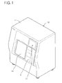
- Fig. 1 shows a perspective view exhibiting the appearance of an apparatus for processing a lens 10.
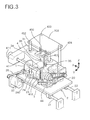
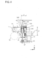
- Fig. 3 and 4 show a front view and a right side view, respectively, exhibiting the inner construction of the apparatus.
- Fig. 1 at the right side of the front of the apparatus for processing a lens 10 contained in a case having the shape of a rectangular parallel-epiped 11, an operation portion 13 for selecting or inputting the processing conditions for the lens and a display portion 12 for displaying information on the processing such as the data of the shape of the lens frame and the data for the processing are disposed.
- the operation portion 13 is constituted with touch panels, touch switches, keys or the like.
- the display portion 12 is constituted with LCD, CRT or the like.
- a door 14 which can be opened or closed as desired and used for inserting or taking out a lens is disposed.
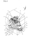
- a base unit 2 which can be displaced in the direction parallel with a main shaft 51 having a main rotating tool 50 (the direction of the X-axis in the Fig.) is disposed at the inside of the case 11.
- the base unit 2 supports a lens unit (a lens-holding unit) 4 which can be displaced in the vertical direction (in the direction of the Z-axis in the Figures).
- the direction from the right to the left in Fig. 2 (the transverse direction of the apparatus for processing a lens 10) is assigned to the X-axis
- the vertical direction (the direction of the height of the apparatus) is assigned to the Z-axis
- the direction from the left to the right in Fig. 4 (the direction towards the inside of the apparatus) is assigned to the Y-axis. It is assumed that these axes orthogonally intersect each other.
- a lens-holding shaft 41 which is divided into two portions and selectively holds the center of the lens 1 between the two portions is disposed in a manner such that the lens-holding shaft can be rotated freely.
- the lens-holding shaft 41 is placed on the vertical line of a rotating tool (a grinder or a cutter) 50 which is supported by a shaft on a base plate 13.
- the lens-holding shaft 41 and the main shaft 51 of the main rotating tool 50 are arranged parallel with each other along the X-axis.
- the lens 1 is held along a plane perpendicular with the axial line of the lens-holding shaft 41.
- a measuring unit 6 comprising styluses 60 and 61 for measuring positions on the concave face and the convex face, respectively, of the lens 1 is fixed on the vertical line of the lens-holding shaft 41.
- the styluses 60 and 61 can be displaced in the direction parallel with the lens-holding shaft 41.
- the styluses 60 and 61 are brought into contact with both faces of the lens 1 in the condition that the lens unit 4 is elevated and the lens unit 4 is elevated or lowered in accordance with the data of the shape of the lens frame while the lens-holding shaft is rotated.
- the lens unit 4 is lowered after the main rotating tool 50 is rotated and the peripheral portion (the outer peripheral portion) of the lens 1 is ground into the prescribed shape by elevating or lowering the lens unit 4 in accordance with the data of the shape of the lens frame while the lens-holding shaft 41 is rotated.
- the grinding to the processing depth in accordance with the rotation angle of the lens 1 is conducted continuously.
- the force of pressing the lens 1 to the main rotating tool 50 (the processing pressure) is provided by the weight of the lens unit 4 itself.
- the adjustment of the processing pressure in accordance with the material of the lens is conducted by supporting a portion of the weight of the lens unit 4 by a unit for controlling the processing pressure 8 disposed at a position above the lens unit 4.
- the position of contact between the lens 1 and the main rotating tool 50 is changed by displacing the base unit 2 in the direction of the X-axis in the Fig. and the selection between the flat grinding and the beveled grinding can be made.
- the switching between the rough grinding and the finishing grinding can also be made similarly.
- a finishing unit 7 which can be displaced in the direction of the Y-axis is disposed at a position above the lens unit 4.
- a rotating tool for chamfering 70 and a rotating tool for grooving 71 are placed at a position directly above the lens-holding shaft 71.
- The, selection between the rotating tools 70 and 71 is made and the position of the processing is set by elevating the lens unit 4 and driving the base unit 2 in the direction of the X-axis.
- the finishing is conducted in this condition.
- the main shaft 51 in which the rotating tool (a grinder or a cutter having diamond or the like) 50 is disposed and a motor 55 for driving the main shaft 51 are fixed to the base plate 15 at the inside of the case 11.
- the main shaft unit 5 is constituted with these members as the main components.
- the main shaft 51 is, as shown in Fig. 2, supported by a shaft on the base plate 15 along the X-axis in a manner such that the main shaft 51 can be rotated freely and is disposed parallel with the lens-holding shaft 41.
- a main rotating tool 50 for mechanically processing the lens 1 is attached at the end portion of the main shaft 51.
- the main rotating tool 50 is placed at the central portion in the direction of the X-axis in Fig. 2 and at the front side of the apparatus (at the lower left side in the Fig.).
- the base end portion of the main shaft (at the right side in the Fig.) is driven by a motor 55 via a belt 57 and pulleys.
- a rough grinder for flat grinding 50a, a finishing grinder for flat grinding 50b, a rough grinder for beveled grinding 50c and a finishing grinder for beveled grinding 50d are disposed successively from the side of the tip of the main shaft 51 (the left side in the Fig.).
- the grinding may also be conducted by using cutters as the rotating tool in place of the grinders.
- a base unit 2 for driving the lens unit 4 in the direction of the X-axis is disposed at a position inside the main shaft 51 in Fig. 2 (in the direction of the Y-axis, at the right side in the Fig.).
- the base unit 2 is constituted with a base 20 which can be displaced in the direction of the X-axis and a servomotor 25 (hereinafter, referred to as an X-axis motor) which controls the positioning by driving the base 20 in the direction of the X-axis as the main components.
- a servomotor 25 hereinafter, referred to as an X-axis motor
- the base 20 is disposed on guide members 21 and 22 which are fixed on the base plate 15 in the direction of the X-axis in a manner such that the base 20 can be freely displaced. Therefore, the base 20 can be freely displaced in the direction of the X-axis.
- an inner screw 23 is disposed at a position below the base 20 between the guide members 21 and 22 in a manner such that the inner screw 23 can be rotated freely.
- An outer screw 24 fixed at the lower face of the base 20 is engaged with the inner screw 23 and the base 20 is driven in the direction of the X-axis by rotation of the screw 23.
- One end of the inner screw 23 and the X-axis motor 25 are connected to each other via a gear and a cogged belt 26 and the base 20 is positioned in the direction of the X-axis in accordance with the rotation angle of the X-axis motor 25.
- four poles 401 to 404 stand on the base 20.
- the two poles 401 and 402 penetrate a frame 40 of the lens unit 4 and guide the lens unit 4 in the vertical direction (the direction of the Z-axis) in a manner such that the lens unit 4 can be displaced freely.
- the lens unit 4 is driven in the vertical direction and positioned in the vertical direction by the elevating and lowering unit 3 which is displaced in the direction of the Z-axis.
- the lens unit 4 is positioned in the direction of the X-axis by the base unit 2.
- the elevating and lowering unit 3 is, as shown in Fig. 3, 4 and 6, constituted with a screw 31 which is supported by a shaft on the base 20 between the poles 401 and 402 and penetrates the frame 40 of the lens unit 4 in the vertical direction, a positioning member 34 which is engaged with the screw 31 at the inner peripheral portion and can support the lens unit 4 by contacting the frame 40 of the lens unit 4 at the upper end and a servomotor 33 (hereinafter, referred to as a Z-axis motor) which is connected to the lower end of the screw 31 via a cogged belt 32 and a gear, as the main components.
- the elevating and lowering unit 3 is disposed on the base 20.
- the screw 31 is rotated by driving the Z-axis motor 33 and the positioning member 34 having an outer screw 35 engaged with the screw 31 is driven in the direction of the Z-axis.
- a stopper 36 is disposed at the side of the outer screw 35 and protrudes towards the lens unit 4.
- the outer screw 35 and the stopper 36 are fixed at the base 340 at the lower end of the positioning member 34.
- the stopper 36 is displaced in the direction of the Z-axis since the stopper 36 is engaged with the lens unit 4 so that rotation in the circumferential direction is restricted.
- the lens unit 4 which is displaced by the elevating and lowering unit 3 in the direction of the Z-axis is, as shown in Fig. 3, guided by the two poles 401 and 402 standing on the base 20 in the vertical direction (in the direction of the Z-axis) in a manner such that the lens unit can be freely displaced and is constituted with the lens-holding shaft 41 which is divided into two portions, a motor 45 for driving the lens which rotates the lens-holding shaft 41 and a motor for the lens chuck 46 which changes the pressure of the lens-holding shaft 41 to hold the lens 1, as the main components.
- the lens-holding shaft 41 which holds and rotates the lens 1 is placed at a position directly above the main rotating tool 50.
- the direction connecting the axial line of the lens-holding shaft 41 and the axial line of the main shaft 51 is in the vertical direction.
- arms 410 and 411 protruding in the direction of the front of the apparatus are disposed and the frame 40 and the arms 410 and 411 form a rectangle having three sides and open to one side.
- the arms 410 and 411 support the lens-holding shaft 41.
- the lens-holding shaft 41 is divided into two portions at the center, i.e., a shaft 41R supported by the arm 410 and a shaft 41L supported by the arm 411.
- the arm 41L is supported by the arm 411 at the left side in Fig. 3 in a manner such that the arm 41L is freely rotated.
- the arm 41R is supported by the arm 410 at the right side in Fig. 3 in a manner such that the arm 41L is freely rotated and can be displaced in the axial direction (in the direction of the X-axis).
- the shafts 41L and 41R are connected with the motor for driving the lens and synchronously rotated.
- the shaft 41R is driven in the axial direction by the lens chuck motor and holds the lens 1 under a prescribed pressure.
- the main rotating tool 50 is fixed to the base plate 13 and is not displaced.
- the lens 1 supported by the lens unit 4 is displaced in the vertical direction relative to the main rotating tool 50 by the displacement of the elevating and lowering unit 3 in the direction of the Z-axis and the desired processing depth can be obtained.
- the position of the lens 1 for the processing can be changed by changing the rotation angle of the motor for driving the lens 46 and the peripheral portion of the lens can be processed to the desired processing depth.
- a sensor for detecting the rotation angle of the lens-holding shaft 41 is disposed at the arm 411 of the lens unit 4.
- the tool used for the processing can be changed by changing the position of contact between the lens 1 and the main rotating tool 50 by the displacement of the base 20 in the direction of the X-axis.
- the waterproof cooling unit for supplying a cooling liquid during the processing of the lens will be described in the following.
- the waterproof cooling unit is used for cooling the uncut lens 1 and the tools, removes dusts of cutting and prevents scattering of the cooling water to the mechanisms outside the processing area.
- a cooling liquid comprising water as the main component is used.
- the waterproof cooling unit comprises as the main components a waterproof case 101 which has the shape of a box and is fixed to a processing area surrounding the main rotating tool 50, the lens 1 supported by the lens-holding shaft 41, the styluses 60 and 61 of the measuring unit 6 and the rotating tools 70 and 71 of the finishing unit 7; a nozzle 102 injecting the cooling liquid to the vicinity of the lens 1 held by the lens-holding shaft 41; a tank 103 disposed at a position below the waterproof case 101; and a pump 104 sending the cooling liquid in the tank 103 to the nozzle 102 under a pressure.
- the waterproof case 101 and the tank 103 are fixed at the base plate 13 in Fig. 2.
- the nozzle 102 is supported by the lens unit 4 and can inject the cooling water always towards the lens 1 independently of the position of the elevating and lowering unit 4.
- the door 14 which can be opened and closed is disposed as shown in Fig. 1.
- the lens is attached or detached.
- the door 14 is closed, the inside of the waterproof case 101 is tightly closed and wetting of the bearing of the main shaft 51, the motors, the power source and the electric circuits with the scattered cooling liquid injected in the waterproof case 101 is prevented.
- the cooling liquid used for cooling the lens 1 and the rotating tools during the processing returns to the tank 103, sucked into the pump 104 and circulated. Since the cooling liquid used for cooling the lens 1 contains dusts formed by processing the lens 1, a drain 105 which can be opened and closed is attached to the tank 103 so that the dusts formed by the cutting can be removed and the cooling liquid can be exchanged with the fresh cooling liquid.
- the main shaft 51 is supported by the base plate 13 at one end portion thereof.
- the main rotating tool 50 disposed at the free end portion of the main shaft 51 is placed in the waterproof case 101 and the main shaft 51 is inserted through a penetrating hole 111 disposed at the side face 110 of the waterproof case 101 shown at the right side in Fig. 5.
- a sealing member 112 is placed between the penetrating hole 111 and the main shaft 51.
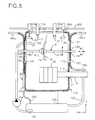
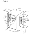
- the lens-holding shaft 41 Since the lens-holding shaft 41 is elevated and lowered along the vertical line of the main shaft 51, as shown in Fig. 5 and 6, long holes 115 and 125 which penetrate the waterproof case 110 in the direction of the X-axis in the prescribed range in the vertical direction are formed at the side faces 110 and 120 of the waterproof case 101 which are placed on the vertical line of the main shaft 51.
- the lens-holding shaft 41 is elevated and lowered while the lens-holding shaft 41 is inserted into the long holes 115 and 125 and the lens 1 is held at the center of the case 101.
- sliding shutters 130 and 140 which are elevated and lowered in combination with the lens-holding shaft 41 are attached to the left side and to the right side, respectively, of the lens-holding shaft 41.
- the sliding shutters 130 and 140 are constituted with a member having a plate shape which can be bent freely with the prescribed elasticity (or flexibility) and having the water-resistant property.
- the sliding shutters may be formed with a resin material such as polyurethane.
- the shaft 41R holding the concave face 1b of the lens 1 is inserted through a penetrating hole 131 of the sliding shutter 130.
- a sealing member 132 is placed between the penetrating hole 131 and the shaft 41L.
- the shaft 41R can be displaced through the sliding shutter 130 in the axial direction, can be rotated freely and is displaced in combination with the sliding shutter 130 in the vertical direction.
- the sliding shutter 130 having the plate shape is displaced inside a guide member 150 which is bent and formed into a shape of a rectangle having three sides and open at one side.
- the sliding shutter 130 is displaced along the longitudinal direction of the guide member 150.
- the guide member 150 has a hollow rectangular sectional shape so that the sliding shutter 130 can be guided with sliding.
- the upper portion 150U of the guide member 150 is bent at a position before the shaft 600 in the horizontal direction (in the axial direction of the lens-holding shaft) towards the outside of the apparatus (to the right side in Fig. 5) so that the interference with the mechanisms at the upper portions of the apparatus can be prevented.
- the lower portion (the lower end portion) 150L of the guide member 150 is bent at a portion between the long hole 151 and the main shaft 51 in the horizontal direction (in the axial direction of the lens-holding shaft) towards the outside of the apparatus (to the right side in Fig. 5) in a manner similar to the upper portion 150U so that the interference with the main shaft 51 can be prevented.
- the lower portion 150L is extended along the main shaft 51 approximately in the horizontal direction (in the direction of the X-axis).
- the middle portion of the guide member 150 contacts the side 110 and is formed in a shape of a straight line.
- the long hole 151 having same shape as the shape of the long hole 115 is formed and penetrates the guide member 150.
- the inner periphery of the waterproof case 101 is tightly closed with the sliding shutter 130.
- the shaft 41L holding the convex face 1a of the lens 1 is inserted through a penetrating hole 141 of the sliding shutter 140.
- a sealing member 142 is placed between the penetrating hole 141 and the shaft 41L.
- the shaft 41L can be displaced through the sliding shutter 140 in the axial direction, can be rotated freely and is displaced in combination with the sliding shutter 140 in the vertical direction.
- the sliding shutter 140 having the plate shape is disposed inside a guide member 160 which has a shape of an inverse L and displaced along the longitudinal direction of the guide member 160.
- the guide member 160 has a hollow rectangular sectional shape so that the sliding shutter 140 can be guided with sliding.
- the upper portion 160U of the guide member 160 is bent in the horizontal direction towards the outside of the apparatus (to the left side in Fig. 5) so that the interference with the mechanisms at the upper portions of the apparatus can be prevented.
- the middle portion to the lower end portion of the guide member 160 contacts the side 120 and is formed in the shape of a straight line.
- the long hole 161 having same shape as the shape of the long hole 125 is formed and penetrates the guide member 160.
- the inner periphery of the waterproof case 101 is tightly closed with the sliding shutter 140.
- the guide member 160 is formed in the shape of a straight line since the main shaft 51 is supported by one end at the right side in the Fig. and no mechanisms or members interfering with the sliding shutter 140 and the guide member 160 are present below the side face 120 of the waterproof case 101 at the left side in the Fig.
- the sliding shutters 130 and 140 which can be displace in the vertical direction in combination with the lens-holding shaft 41 slide at the inside of the guide members 150 and 160, respectively, which are formed in the bent shape so that the interference with the mechanisms above or below the sliding shutters is prevented.
- a penetrating hole 190 (a first penetrating hole) having the shape of a long hole through which shafts 60A and 61A of the styluses 60 and 61, respectively, of the measuring unit displaced in the direction of the X-axis are inserted is formed at a position directly above the lens-holding shaft 41.
- Penetrating holes 193 and 194 (second penetrating holes), through which sleeves 70A and 71A, respectively, containing shafts of the rotating tools 70 and 71, respectively, of the finishing unit 7 displaced in the direction of the Y-axis during the chamfering or the grooving are inserted, are also formed.
- the penetrating hole 190 intersects the penetrating holes 193 and 194 and these holes form a continuous single opening.
- concave portions 191 and 192 having a circular shape and engaged with portions of the 70A and 71A, respectively, are formed in the penetrating hole 190 and penetrate the upper face 101U.
- an upper waterproof unit which prevents the scattering of water in accordance with the displacement of the measuring unit 6 and the finishing unit 7 is disposed.
- a frame 200 is fixed in the horizontal direction.
- the measuring unit 6 is fixed at the frame 200 and shafts 60A and 61A of the styluses 60 and 61, respectively, are disposed downwards.
- the sleeves 70A and 71A of the rotating tools 70 and 71 are disposed on the base 74 which can be displaced in the direction of the Y-axis on the frame 200.
- a motor 72 connected with the sleeves via belts stands on the base 74.
- the base 74 is displaced in the direction of the Y-axis (in the direction intersecting (perpendicularly) the lens-holding shaft 41) and drives the rotating tools 70 and 71.
- the base 74 is advanced or retired between the prescribed position for processing (the position where the axial lines of the rotating tools 70 and 71 are placed at positions vertically above the lens-holding shaft) and the prescribed waiting position (the position where the axial lines of the rotating tool 70 and 71 are separated from the positions vertically above the lens holding-shaft by the prescribed distance in the direction of the Y-axis) by a motor not shown in the Fig..
- the base 74 is advanced to the prescribed waterproof position.
- the sleeves 70A and 71A protrude at the inside of the waterproof case 101 and a shutter having a plate shape 170 is fixed to the sleeves 70A and 71A towards the styluses 60 and 61.
- the shutter 170 has a size such that, when the styluses are placed at the waiting positions and the base 74 is placed at the/position advanced by the prescribed distance (at the waterproof position), the penetrating hole 190 between the shafts 60A and 61A and the penetrating holes 193 and 194 through which the sleeves 70A and 71A, respectively, are inserted are closed.
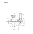
- a shutter 171 having the shape of a plate or a cloth and flexible is disposed at the sleeves 70A and 71A and extends towards the inside of the apparatus (towards the right side in Fig. 9).
- the shutter 171 closes the penetrating holes 193 and 194 placed at the positions inside the sleeves 70A and 71A, respectively, when the base 74 is displaced to the prescribed finishing position (where the rotating tools are placed at positions vertically above the lens-holding shaft 41). Since the shutter 171 is flexible, as shown in Fig. 8 and 9, the shutter 171 can be displaced along the penetrating holes 193 and 194 in accordance with the advancement and the retirement of the base 74 and can close the penetrating holes 194 and 194. Dangling of the shutter 171 towards the lens 1 is prevented by a guide shaft 172 disposed in the direction of the X-axis at a position further inside the waterproof case 101.
- swinging shutters 180 and 181 which are swung in the horizontal direction around the shafts 182 and 183, respectively, and selectively closes the concave portions 191 and 192, respectively, are disposed.
- the swinging shutters 180 and 181 are connected to each other by a return spring 184 at each portion at the side of the front of the apparatus (at the lower side in Fig. 10 and at the left side in Fig. 9).
- the swinging shutters 180 and 181 are pushed towards the positions closing the concave portions 191 and 192.
- stoppers not shown in the Figures for arresting the swinging shutters 180 and 181 are disposed and the swinging shutters 180 and 181 are kept at the positions closing the concave portions 191 and 192, respectively.
- the finishing unit 7 When the processing is not conducted, as shown in Fig. 14, the finishing unit 7 is placed at the waiting position at the upper side in the Fig. and the sleeves 70A and 71A are placed at the end portion of the penetrating holes 193 and 194 having the shape of a long hole, respectively.
- the shutter having the plate shape 170 protruding from the sleeve 70A and 71A towards the styluses (towards the front of the apparatus) leaves the penetrating hole 190 open and the displacement of the styluses 60 and 61 in the direction of the X-axis is allowed.
- the base 74 is advanced by the prescribed distance to the position where the tip of the shutter 170 (the end portion at the side of the penetrating hole 190) is placed beyond the penetrating hole 190 and the penetrating hole 190 is completely closed (the displacement towards the position at the front of the apparatus or the position vertically above the lens-holding shaft 41).
- the penetrating holes 190 between the shafts 60A and 61A of the styluses 60 and 16, respectively, and the penetrating holes 193 and 194 through which the sleeves 70A and 71A, respectively, are inserted are closed by the shutter 170 and the concave portions 191 and 192 are closed by the swinging shutters 180 and 181, respectively. Therefore, scattering of the cooling liquid injected towards the lens 1 at the outside is prevented by the shutters 170, 180 and 181.
- the rotating tools 70 and 71 are advance to the positions for finishing where the rotating tools are faced to the lens 1 on the vertical line of the lens-holding shaft.
- a portion of the sleeves 70A and 71A closes the concave portions 191 and 192, respectively, and the sleeves 70A and 71A rotates the shutters 180 and 181, respectively, by pushing the shutters.
- the advanced shutter 170 closes the penetrating hole 190.
- the penetrating holes 193 and 194 at the positions further inside the apparatus from the sleeves 70A and 71A (at the upper side in Fig. 13 and at the right side in Fig. 12) are closed by the shutter 171 which is pulled and displaced by the sleeves 70A and 71A.
- the concave portions 191 and 192 are closed by the sleeves 70A and 71A, respectively, and the penetrating hole 190 is closed by the shutter 170.
- the penetrating holes 193 and 194 are closed by the shutter 171. Therefore, the scattering of the cooling liquid injected towards the lens 1 at the outside is prevented by the shutters 170 and 171.
- the swinging shutters 180 and 181 are swung to the prescribed positions by being pulled by the spring 184 (the elastic member) and closes the concave portions 191 and 192.
- the shutter 170 is displaced to the position at the inside of the apparatus and the penetrating hole 190 is opened.
- the styluses 60 and 61 can be displaced in the direction of the X-axis in this condition.
- the penetrating hole 111 through which the main shaft 51 supported on the base plate 13 is inserted and the long holes 115 and 125 through which the lens-holding shaft 41 freely displaced in the vertical direction is inserted are formed on the waterproof case 101 covering the area of processing the lens 1 in a manner such that the holes penetrate the waterproof case 101.
- the penetrating hole 111 and the main shaft 51 are sealed from water by the sealing member 112.
- the right and left long holes 115 and 125 are sealed from water by the sliding shutters 130 and 140, respectively, which are each connected to the lens-holding shaft 41 in the form extending in the direction of the displacement of the lens-holding shaft 41 (in the direction along the range of displacement). Scattering of the cooling liquid at the outside of the waterproof case 101 is thus prevented.
- the guide member 150 guiding the sliding shutter 130 has the long hole 151 having the same shape as that of the long hole 115 formed at the same position as that of the long hole 115. Since the lower portion 150L of the guide member 150 below the long hole 151 is bent to the right side in the Fig. along the main shaft 51, the lower end portion of the sliding shutter 130 is guided by the bent portion of the guide member 150 and contained in the lower portion 150L which extends along and above the main shaft 51.
- the direction of the sliding shutter 130 is the vertical direction along the side face 110 of the waterproof case 101 at portions faced to the long hole 151, the direction is changed to the horizontal direction by the bent guide member 150 at the portion below the long hole 151.
- the sliding shutter 130 is formed into a plate shape with a freely flexible water-resistant material and can slide along the inner peripheral portion of the guide member 150, the interference of the main shaft 51 and the sliding shutter 130 can be prevented while the penetrating hole (the long hole 151) of the waterproof case 101 through which the lens-holding shaft displaced towards the main shaft 51 is inserted is surely sealed from water even when mechanisms such as the maim shaft 51 of the main rotating tool 50 are present on the extension of the direction of displacement of the lens-holding shaft.
- the present invention is remarkably effective.
- the guide members of the sliding shutters can be disposed utilizing spaces such as spaces at the sides of the waterproof case.
- the relation between the main shaft 51 of the main rotating tool 50 and the lens-holding shaft 41 can be designed more freely than that in conventional cases. Therefore, an apparatus exhibiting an excellent balance between the waterproof property and the processing property can be provided.
- the waterproof case 101 covers only the area of processing containing the main rotating tool 50, the lens 1, the lens-holding shaft 41, the styluses 60 and 61 of the measuring unit 6 and the rotating tools 70 and 71 of the processing unit 7, the area of exposure of the mechanisms such as the main shaft 51 and the lens unit 4 to the cooling liquid is kept at the minimum and the durability of the apparatus can be increased.
- the lens-holding shaft is displaced in the vertical direction towards the main shaft 51.
- the present invention is not limited to this embodiment.
- the waterproof mechanism can be surely provided by using a bent guide member containing a flexible water-resistant sliding shutter at the inside and connecting the guide member with the lens-holding shaft 41 even when the main shaft 51 is present on the extension of the locus of the displacement of the lens-holding shaft 41.
- the present invention can be applied to the case in which a sliding shutter for closing openings along the lens-holding shaft from water interferes not only with the main shaft but also with other mechanisms and members.
Landscapes
- Engineering & Computer Science (AREA)
- Mechanical Engineering (AREA)
- Chemical & Material Sciences (AREA)
- Ceramic Engineering (AREA)
- Inorganic Chemistry (AREA)
- Grinding And Polishing Of Tertiary Curved Surfaces And Surfaces With Complex Shapes (AREA)
- Eyeglasses (AREA)
- Grinding-Machine Dressing And Accessory Apparatuses (AREA)
Abstract
Description
- Fig. 1
- shows a perspective view of the appearance of the apparatus for processing a lens as an embodiment of the present invention;
- Fig. 2
- shows a perspective view exhibiting the main portions of the inner construction;
- Fig. 3
- shows a perspective view exhibiting a base unit, an elevating and lowering unit and a lens unit in the inner construction;
- Fig. 4
- shows a sectional view of the elevating and lowering unit and the lens unit in the vertical direction when the processing is started;
- Fig. 5
- shows a sectional view of the main portions of a waterproof case in a waterproof cooling mechanism;
- Fig. 6
- shows a perspective view of the waterproof case;
- Fig. 7
- shows a plan view exhibiting the upper face of the waterproof case;
- Fig. 8
- shows a perspective view of an upper portion of the waterproof case, exhibiting the positions of waterproof members for sealing the finishing unit from water.
- Fig. 9
- shows a sectional view of an upper portion of the waterproof case, exhibiting the positions of sealing the finishing unit from water;
- Fig. 10
- shows a plan view of an upper portion of the waterproof case, exhibiting the positions of sealing the finishing unit from water;
- Fig.
- 11 shows a perspective view of an upper portion of the waterproof case, exhibiting the positions when the finishing unit is at the processing position;
- Fig. 12
- shows a sectional view of an upper portion of the waterproof case, exhibiting the positions when the finishing unit is at the processing position;
- Fig. 13
- shows a plan view of an upper portion of the waterproof case, exhibiting the positions when the finishing unit is at the processing position;
- Fig. 14
- shows a plan view of an upper portion of the waterproof case, exhibiting the positions when the finishing unit is at the waiting position.
- 1:
- A lens
- 2:
- A base unit
- 3:
- An elevating and lowering unit
- 4:
- A lens unit
- 10:
- An apparatus for processing a lens
- 11:
- A cover
- 41:
- A lens-holding shaft
- 51:
- A main shaft
- 101:
- A waterproof case
- 130 and 140:
- Sliding shutters
- 150 and 160:
- Guide members
- 170:
- A shutter
- 171:
- A shutter
Claims (7)
- An apparatus for processing a lens which comprises in a waterproof case a lens-holding shaft which holds a lens and a processing means which processes the lens and processes a peripheral portion of the lens while the lens-holding shaft is displaced towards said processing means and a cooling liquid is injected towards the lens; whereina long hole is formed along a locus of displacement of the lens-holding shaft at a portion of the waterproof case where the lens-holding shaft penetrates the waterproof case;a sliding shutter which closes the long hole and is freely flexible is connected to the lens-holding shaft; anda guide member which guides the sliding shutter is bent in an axial direction of the lens-holding shaft at an outside of the long hole.
- An apparatus according to claim 1, wherein the processing means comprises a main shaft parallel with the lens-holding shaft and the guide member is bent at a position between the long hole and the main shaft.
- An apparatus according to claim 1 or 2, which further comprises a drain for discharging the cooling liquid accumulated at a lower portion or at an inside of the guide member.
- An apparatus according to claim 2 or 3, wherein the waterproof case stands in a vertical direction, the lens-holding shaft is displaced in a vertical direction above the main shaft, and the guide member is disposed in a vertical direction at a position faced to the long hole and is bent above the main shaft towards an outside of the apparatus.
- An apparatus for processing a lens which comprises in a waterproof case a lens-holding shaft which holds a lens, a finishing means which chamfers or grooves a peripheral portion of the lens and a measurement means which measures a peripheral shape of the lens, and processes a peripheral portion of the lens while the lens-holding shaft is displaced towards the processing means and a cooling liquid is injected towards the lens; whereinthe holding shaft is elevated and lowered in a vertical direction;the measurement means is fixed on an upper face of the waterproof case and supports a pair of measuring devices protruding towards an inside of the waterproof case in a manner such that the measuring device can be displaced along the holding shaft;the finishing means is disposed on the upper face of the waterproof case and supports rotating tools for processing a peripheral portion of the lens in a manner such that the rotating tools can be displaced between a position vertically above the holding shaft and a prescribed waiting position in a direction intersecting the holding shaft;a first penetrating hole having a shape of a long hole is formed on the upper face of the waterproof case in accordance with a range of displacement of the measuring device along the holding shaft;second penetrating holes are formed on the upper face of the waterproof case in accordance with a range of displacement of the rotating tools in a direction intersecting the holding shaft; andshutters which can close the first penetrating hole and the second penetrating holes at an inner periphery of the waterproof case are disposed at a side of the rotating tool.
- An apparatus according to claim 5, whereinthe finishing means comprises a base which is disposed on the upper face of the waterproof case and displaced towards the holding shaft, sleeves which are fixed at the base and protrude into an inside of the waterproof case and the rotating tools disposed at lower ends of the sleeves; andthe shutters comprise a first shutter disposed at the sleeves towards the first penetrating hole in a horizontal direction along the inside of the waterproof case and a second shutter disposed at the sleeves at a side opposite to a side of the first penetrating hole.
- An apparatus according to claim 6, wherein concave portions which can be engaged with portions of the sleeves are formed at a position intersecting the second penetrating holes in the first penetrating hole and penetrate the first penetrating hole, and swinging shutters which selectively close the concave portions in accordance with displacement of the sleeves are disposed at the upper face of the waterproof case.
Applications Claiming Priority (2)
| Application Number | Priority Date | Filing Date | Title |
|---|---|---|---|
| JP2002105566 | 2002-04-08 | ||
| JP2002105566A JP2003300158A (en) | 2002-04-08 | 2002-04-08 | Lens processing equipment |
Publications (3)
| Publication Number | Publication Date |
|---|---|
| EP1352705A2 true EP1352705A2 (en) | 2003-10-15 |
| EP1352705A3 EP1352705A3 (en) | 2003-11-26 |
| EP1352705B1 EP1352705B1 (en) | 2005-08-31 |
Family
ID=28449908
Family Applications (1)
| Application Number | Title | Priority Date | Filing Date |
|---|---|---|---|
| EP03007807A Expired - Lifetime EP1352705B1 (en) | 2002-04-08 | 2003-04-04 | Apparatus for processing a lens |
Country Status (7)
| Country | Link |
|---|---|
| US (1) | US6800017B2 (en) |
| EP (1) | EP1352705B1 (en) |
| JP (1) | JP2003300158A (en) |
| KR (1) | KR100496558B1 (en) |
| CN (1) | CN1203964C (en) |
| AT (1) | ATE303230T1 (en) |
| DE (1) | DE60301422T2 (en) |
Cited By (4)
| Publication number | Priority date | Publication date | Assignee | Title |
|---|---|---|---|---|
| GB2452575A (en) * | 2007-09-10 | 2009-03-11 | Christopher Peter Devereux | Tungsten electrode grinder |
| EP2669047A3 (en) * | 2012-05-31 | 2014-11-05 | Nidek Co., Ltd | Eyeglass lens processing apparatus |
| CN112659200A (en) * | 2020-11-16 | 2021-04-16 | 江苏悦达兴业汽车配件有限公司 | Automobile spare and accessory part cutting equipment with cooling function |
| TWI880296B (en) * | 2023-08-08 | 2025-04-11 | 大陸商業成科技(成都)有限公司 | Clamping device |
Families Citing this family (25)
| Publication number | Priority date | Publication date | Assignee | Title |
|---|---|---|---|---|
| FR2870471B1 (en) * | 2004-05-18 | 2006-08-25 | Briot Internat Sa | METHOD OF GROOVING OR CONTRABESAUTING THE PERIPHERY OF AN OPHTHALMIC LENS |
| US20060205321A1 (en) * | 2005-03-11 | 2006-09-14 | United Technologies Corporation | Super-abrasive machining tool and method of use |
| FR2884163B1 (en) * | 2005-04-07 | 2007-07-06 | Briot Internat Sa | OPTICAL GLASS GRINDING MACHINE WITH INCLINED FINISHING WHEEL AND CORRESPONDING OPTICAL GLASS |
| JP5073338B2 (en) * | 2007-03-28 | 2012-11-14 | 株式会社ニデック | Lens fixing cup |
| DE102007042667A1 (en) * | 2007-09-10 | 2009-03-12 | Schneider Gmbh & Co. Kg | Polishing machine for lenses and method for polishing a lens with a processing machine |
| KR100962870B1 (en) | 2008-06-16 | 2010-06-10 | 현대자동차주식회사 | Cam ring inner diameter measurement and grinding device for power steering oil pump |
| WO2012045411A1 (en) * | 2010-10-04 | 2012-04-12 | Schneider Gmbh & Co. Kg | Apparatus and method for working an optical lens and also an optical lens and a transporting container for optical lenses |
| FR2966072B1 (en) * | 2010-10-15 | 2012-10-19 | Essilor Int | CALIBRATION JIG FOR A MACHINE FOR MACHINING AN OPHTHALMIC LENS, DEVICE AND METHOD USING SUCH A JIG |
| JP5935407B2 (en) * | 2012-03-09 | 2016-06-15 | 株式会社ニデック | Eyeglass lens processing equipment |
| JP6347317B2 (en) * | 2014-01-14 | 2018-06-27 | 株式会社ニデック | Eyeglass lens processing apparatus and eyeglass lens processing program |
| KR101597910B1 (en) | 2014-12-03 | 2016-02-25 | 민병직 | Apparatus for processing a lens |
| EP3075508B1 (en) * | 2015-03-31 | 2019-07-31 | Nidek co., Ltd. | Eyeglass lens processing apparatus, eyeglass lens processing control data acquisition apparatus and eyeglass lens processing method |
| KR101590748B1 (en) | 2015-05-06 | 2016-02-01 | 민병직 | Apparatus for processing a astigmatic lens |
| KR101590749B1 (en) | 2015-05-06 | 2016-02-18 | 민병직 | Apparatus for processing a astigmatic lens |
| CN106903549B (en) * | 2015-12-22 | 2020-07-07 | 重庆大学 | Gear dry type hobbing cutting protection device |
| JP6766400B2 (en) * | 2016-03-28 | 2020-10-14 | 株式会社ニデック | Eyeglass lens processing equipment and eyeglass lens processing program |
| KR101869687B1 (en) * | 2016-07-21 | 2018-06-21 | 주식회사 휴비츠 | Apparatus for processing eyeglass lens |
| CN109500690B (en) * | 2018-11-20 | 2021-04-20 | 重庆理工大学 | Continuous automatic lens polishing method |
| CN109318078B (en) * | 2018-11-20 | 2020-11-17 | 重庆理工大学 | Full-automatic lens edging machine |
| CN110640575B (en) * | 2019-11-15 | 2020-08-04 | 江西弘耀光学水晶有限公司 | Optical instrument for polishing lens |
| CN111929798A (en) * | 2020-10-14 | 2020-11-13 | 武汉工程大学 | Large-caliber optical element clamping and adjusting device |
| CN112276718B (en) * | 2020-10-23 | 2021-10-01 | 邵阳学院 | A small plano-convex lens edge grinding and polishing equipment |
| CN112536677B (en) * | 2020-12-07 | 2022-12-06 | 光皓光学(江苏)有限公司 | Optical lens piece grinding device of high factor of safety |
| CN112454073B (en) * | 2020-12-08 | 2022-05-13 | 南京灵雀智能制造有限公司 | Multi-focus children glasses processing device |
| CN118456183B (en) * | 2024-05-11 | 2024-10-29 | 江苏福旭科技有限公司 | A semiconductor integrated circuit wafer processing production line |
Family Cites Families (7)
| Publication number | Priority date | Publication date | Assignee | Title |
|---|---|---|---|---|
| FR2557000B1 (en) | 1983-12-23 | 1987-08-07 | Essilor Int | GRINDING STATION FOR GRINDING MACHINE, PARTICULARLY FOR THE BEVELING OR GROOVING OF AN OPHTHALMIC LENS |
| DE3608957C2 (en) | 1986-03-18 | 1994-02-10 | Wernicke & Co Gmbh | Spectacle lens edge grinding machine |
| JPH09225799A (en) | 1996-02-21 | 1997-09-02 | Hoya Corp | Processing method of edge trimming device |
| JP3168328B2 (en) | 1999-07-12 | 2001-05-21 | ホーコス株式会社 | Machine tool and its cover device |
| JP3961196B2 (en) | 2000-06-15 | 2007-08-22 | 株式会社ニデック | Eyeglass lens processing equipment |
| US6572460B2 (en) * | 2001-01-31 | 2003-06-03 | Nidek Co., Ltd. | Tank unit for grinding water used in processing eyeglass lens, and eyeglass lens processing apparatus having the same |
| JP4322464B2 (en) * | 2002-03-28 | 2009-09-02 | 株式会社ニデック | Grinding water tank apparatus and spectacle lens processing apparatus including the same. |
-
2002
- 2002-04-08 JP JP2002105566A patent/JP2003300158A/en active Pending
-
2003
- 2003-03-14 KR KR10-2003-0016103A patent/KR100496558B1/en not_active Expired - Fee Related
- 2003-04-04 US US10/406,606 patent/US6800017B2/en not_active Expired - Fee Related
- 2003-04-04 AT AT03007807T patent/ATE303230T1/en not_active IP Right Cessation
- 2003-04-04 DE DE60301422T patent/DE60301422T2/en not_active Expired - Lifetime
- 2003-04-04 EP EP03007807A patent/EP1352705B1/en not_active Expired - Lifetime
- 2003-04-08 CN CNB031095186A patent/CN1203964C/en not_active Expired - Fee Related
Cited By (4)
| Publication number | Priority date | Publication date | Assignee | Title |
|---|---|---|---|---|
| GB2452575A (en) * | 2007-09-10 | 2009-03-11 | Christopher Peter Devereux | Tungsten electrode grinder |
| EP2669047A3 (en) * | 2012-05-31 | 2014-11-05 | Nidek Co., Ltd | Eyeglass lens processing apparatus |
| CN112659200A (en) * | 2020-11-16 | 2021-04-16 | 江苏悦达兴业汽车配件有限公司 | Automobile spare and accessory part cutting equipment with cooling function |
| TWI880296B (en) * | 2023-08-08 | 2025-04-11 | 大陸商業成科技(成都)有限公司 | Clamping device |
Also Published As
| Publication number | Publication date |
|---|---|
| EP1352705B1 (en) | 2005-08-31 |
| EP1352705A3 (en) | 2003-11-26 |
| CN1449891A (en) | 2003-10-22 |
| DE60301422T2 (en) | 2006-06-29 |
| KR100496558B1 (en) | 2005-06-22 |
| US20030214627A1 (en) | 2003-11-20 |
| US6800017B2 (en) | 2004-10-05 |
| ATE303230T1 (en) | 2005-09-15 |
| CN1203964C (en) | 2005-06-01 |
| KR20030081022A (en) | 2003-10-17 |
| JP2003300158A (en) | 2003-10-21 |
| DE60301422D1 (en) | 2005-10-06 |
Similar Documents
| Publication | Publication Date | Title |
|---|---|---|
| EP1352705B1 (en) | Apparatus for processing a lens | |
| ES2372534T3 (en) | GLASS LENS PROCESSING DEVICE. | |
| EP1352704B1 (en) | Apparatus for processing the circumference of a spectacle lens with a vertically displaceable lens holder | |
| US6241577B1 (en) | Lens grinding apparatus and lens grinding method and component therefor | |
| EP1366856A2 (en) | Apparatus for processing a lens and a process for processing a lens | |
| EP1352706B1 (en) | Apparatus for processing the circumference of a spectacle lens with a finishing unit for chamfering and grooving | |
| US20070202775A1 (en) | Eyeglass lens processing system | |
| CN105563237A (en) | Machining apparatus for multiple faces | |
| US7377729B2 (en) | Method of drilling holes in lenses by means of a numerically-controlled drill and apparatus for implementing said method | |
| US20060281392A1 (en) | Lens edger | |
| JP2004009201A (en) | Rimless lens drilling device and lens grinding device using the same | |
| EP1352707B1 (en) | Apparatus for processing a lens | |
| US6648738B2 (en) | Grinding fluid supply device of lens grinding apparatus | |
| CN214418165U (en) | Turning and polishing integrated machine for machining | |
| US6499816B1 (en) | Grinding machine enclosure | |
| JP4401502B2 (en) | Lens grinding machine | |
| JP2007007787A (en) | Spectacle lens machining device | |
| JP2022167523A (en) | OIL APPLICATION DEVICE, BENDING MACHINE, AND OIL APPLICATION METHOD | |
| KR102423787B1 (en) | Machine for Internal Grinding of Pipe | |
| JP3017287U (en) | Work processing device | |
| KR200301055Y1 (en) | Cutting position display device of blade tip | |
| JPH11138405A (en) | Lens grinding apparatus and lens manufacturing method | |
| KR20020001004A (en) | An apparatus for removing the deformed strip and polishing the surface of the scratched roll |
Legal Events
| Date | Code | Title | Description |
|---|---|---|---|
| PUAI | Public reference made under article 153(3) epc to a published international application that has entered the european phase |
Free format text: ORIGINAL CODE: 0009012 |
|
| PUAL | Search report despatched |
Free format text: ORIGINAL CODE: 0009013 |
|
| AK | Designated contracting states |
Kind code of ref document: A2 Designated state(s): AT BE BG CH CY CZ DE DK EE ES FI FR GB GR HU IE IT LI LU MC NL PT SE SI SK TR |
|
| AX | Request for extension of the european patent |
Extension state: AL LT LV MK RO |
|
| AK | Designated contracting states |
Kind code of ref document: A3 Designated state(s): AT BE BG CH CY CZ DE DK EE ES FI FR GB GR HU IE IT LI LU MC NL PT SE SI SK TR |
|
| AX | Request for extension of the european patent |
Extension state: AL LT LV MK RO |
|
| RIC1 | Information provided on ipc code assigned before grant |
Ipc: 7B 23Q 11/08 B Ipc: 7B 24B 55/02 B Ipc: 7B 24B 55/04 B Ipc: 7B 24B 9/14 A |
|
| 17P | Request for examination filed |
Effective date: 20031208 |
|
| AKX | Designation fees paid |
Designated state(s): AT BE BG CH CY CZ DE DK EE ES FI FR GB GR HU IE IT LI LU MC NL PT SE SI SK TR |
|
| 17Q | First examination report despatched |
Effective date: 20041104 |
|
| GRAP | Despatch of communication of intention to grant a patent |
Free format text: ORIGINAL CODE: EPIDOSNIGR1 |
|
| GRAS | Grant fee paid |
Free format text: ORIGINAL CODE: EPIDOSNIGR3 |
|
| GRAA | (expected) grant |
Free format text: ORIGINAL CODE: 0009210 |
|
| AK | Designated contracting states |
Kind code of ref document: B1 Designated state(s): AT BE BG CH CY CZ DE DK EE ES FI FR GB GR HU IE IT LI LU MC NL PT SE SI SK TR |
|
| PG25 | Lapsed in a contracting state [announced via postgrant information from national office to epo] |
Ref country code: SI Free format text: LAPSE BECAUSE OF FAILURE TO SUBMIT A TRANSLATION OF THE DESCRIPTION OR TO PAY THE FEE WITHIN THE PRESCRIBED TIME-LIMIT Effective date: 20050831 Ref country code: CZ Free format text: LAPSE BECAUSE OF FAILURE TO SUBMIT A TRANSLATION OF THE DESCRIPTION OR TO PAY THE FEE WITHIN THE PRESCRIBED TIME-LIMIT Effective date: 20050831 Ref country code: IT Free format text: LAPSE BECAUSE OF FAILURE TO SUBMIT A TRANSLATION OF THE DESCRIPTION OR TO PAY THE FEE WITHIN THE PRESCRIBED TIME-LIMIT;WARNING: LAPSES OF ITALIAN PATENTS WITH EFFECTIVE DATE BEFORE 2007 MAY HAVE OCCURRED AT ANY TIME BEFORE 2007. THE CORRECT EFFECTIVE DATE MAY BE DIFFERENT FROM THE ONE RECORDED. Effective date: 20050831 Ref country code: BE Free format text: LAPSE BECAUSE OF FAILURE TO SUBMIT A TRANSLATION OF THE DESCRIPTION OR TO PAY THE FEE WITHIN THE PRESCRIBED TIME-LIMIT Effective date: 20050831 Ref country code: FI Free format text: LAPSE BECAUSE OF FAILURE TO SUBMIT A TRANSLATION OF THE DESCRIPTION OR TO PAY THE FEE WITHIN THE PRESCRIBED TIME-LIMIT Effective date: 20050831 Ref country code: SK Free format text: LAPSE BECAUSE OF FAILURE TO SUBMIT A TRANSLATION OF THE DESCRIPTION OR TO PAY THE FEE WITHIN THE PRESCRIBED TIME-LIMIT Effective date: 20050831 Ref country code: AT Free format text: LAPSE BECAUSE OF FAILURE TO SUBMIT A TRANSLATION OF THE DESCRIPTION OR TO PAY THE FEE WITHIN THE PRESCRIBED TIME-LIMIT Effective date: 20050831 Ref country code: LI Free format text: LAPSE BECAUSE OF FAILURE TO SUBMIT A TRANSLATION OF THE DESCRIPTION OR TO PAY THE FEE WITHIN THE PRESCRIBED TIME-LIMIT Effective date: 20050831 Ref country code: CH Free format text: LAPSE BECAUSE OF FAILURE TO SUBMIT A TRANSLATION OF THE DESCRIPTION OR TO PAY THE FEE WITHIN THE PRESCRIBED TIME-LIMIT Effective date: 20050831 |
|
| REG | Reference to a national code |
Ref country code: GB Ref legal event code: FG4D Ref country code: CH Ref legal event code: EP |
|
| REG | Reference to a national code |
Ref country code: IE Ref legal event code: FG4D |
|
| REF | Corresponds to: |
Ref document number: 60301422 Country of ref document: DE Date of ref document: 20051006 Kind code of ref document: P |
|
| PG25 | Lapsed in a contracting state [announced via postgrant information from national office to epo] |
Ref country code: SE Free format text: LAPSE BECAUSE OF FAILURE TO SUBMIT A TRANSLATION OF THE DESCRIPTION OR TO PAY THE FEE WITHIN THE PRESCRIBED TIME-LIMIT Effective date: 20051130 Ref country code: GR Free format text: LAPSE BECAUSE OF FAILURE TO SUBMIT A TRANSLATION OF THE DESCRIPTION OR TO PAY THE FEE WITHIN THE PRESCRIBED TIME-LIMIT Effective date: 20051130 Ref country code: DK Free format text: LAPSE BECAUSE OF FAILURE TO SUBMIT A TRANSLATION OF THE DESCRIPTION OR TO PAY THE FEE WITHIN THE PRESCRIBED TIME-LIMIT Effective date: 20051130 Ref country code: BG Free format text: LAPSE BECAUSE OF FAILURE TO SUBMIT A TRANSLATION OF THE DESCRIPTION OR TO PAY THE FEE WITHIN THE PRESCRIBED TIME-LIMIT Effective date: 20051130 |
|
| PG25 | Lapsed in a contracting state [announced via postgrant information from national office to epo] |
Ref country code: PT Free format text: LAPSE BECAUSE OF FAILURE TO SUBMIT A TRANSLATION OF THE DESCRIPTION OR TO PAY THE FEE WITHIN THE PRESCRIBED TIME-LIMIT Effective date: 20060223 |
|
| PG25 | Lapsed in a contracting state [announced via postgrant information from national office to epo] |
Ref country code: HU Free format text: LAPSE BECAUSE OF FAILURE TO SUBMIT A TRANSLATION OF THE DESCRIPTION OR TO PAY THE FEE WITHIN THE PRESCRIBED TIME-LIMIT Effective date: 20060301 |
|
| REG | Reference to a national code |
Ref country code: CH Ref legal event code: PL |
|
| PG25 | Lapsed in a contracting state [announced via postgrant information from national office to epo] |
Ref country code: IE Free format text: LAPSE BECAUSE OF NON-PAYMENT OF DUE FEES Effective date: 20060404 |
|
| PG25 | Lapsed in a contracting state [announced via postgrant information from national office to epo] |
Ref country code: MC Free format text: LAPSE BECAUSE OF NON-PAYMENT OF DUE FEES Effective date: 20060430 |
|
| ET | Fr: translation filed | ||
| PLBE | No opposition filed within time limit |
Free format text: ORIGINAL CODE: 0009261 |
|
| STAA | Information on the status of an ep patent application or granted ep patent |
Free format text: STATUS: NO OPPOSITION FILED WITHIN TIME LIMIT |
|
| 26N | No opposition filed |
Effective date: 20060601 |
|
| REG | Reference to a national code |
Ref country code: IE Ref legal event code: MM4A |
|
| PG25 | Lapsed in a contracting state [announced via postgrant information from national office to epo] |
Ref country code: EE Free format text: LAPSE BECAUSE OF FAILURE TO SUBMIT A TRANSLATION OF THE DESCRIPTION OR TO PAY THE FEE WITHIN THE PRESCRIBED TIME-LIMIT Effective date: 20050831 |
|
| PG25 | Lapsed in a contracting state [announced via postgrant information from national office to epo] |
Ref country code: LU Free format text: LAPSE BECAUSE OF NON-PAYMENT OF DUE FEES Effective date: 20060404 Ref country code: TR Free format text: LAPSE BECAUSE OF FAILURE TO SUBMIT A TRANSLATION OF THE DESCRIPTION OR TO PAY THE FEE WITHIN THE PRESCRIBED TIME-LIMIT Effective date: 20050831 |
|
| PG25 | Lapsed in a contracting state [announced via postgrant information from national office to epo] |
Ref country code: CY Free format text: LAPSE BECAUSE OF FAILURE TO SUBMIT A TRANSLATION OF THE DESCRIPTION OR TO PAY THE FEE WITHIN THE PRESCRIBED TIME-LIMIT Effective date: 20050831 |
|
| PG25 | Lapsed in a contracting state [announced via postgrant information from national office to epo] |
Ref country code: ES Free format text: LAPSE BECAUSE OF NON-PAYMENT OF DUE FEES Effective date: 20060430 |
|
| PGFP | Annual fee paid to national office [announced via postgrant information from national office to epo] |
Ref country code: GB Payment date: 20130403 Year of fee payment: 11 Ref country code: DE Payment date: 20130327 Year of fee payment: 11 |
|
| PGFP | Annual fee paid to national office [announced via postgrant information from national office to epo] |
Ref country code: FR Payment date: 20130625 Year of fee payment: 11 Ref country code: NL Payment date: 20130416 Year of fee payment: 11 |
|
| REG | Reference to a national code |
Ref country code: DE Ref legal event code: R119 Ref document number: 60301422 Country of ref document: DE |
|
| REG | Reference to a national code |
Ref country code: NL Ref legal event code: V1 Effective date: 20141101 |
|
| GBPC | Gb: european patent ceased through non-payment of renewal fee |
Effective date: 20140404 |
|
| REG | Reference to a national code |
Ref country code: DE Ref legal event code: R119 Ref document number: 60301422 Country of ref document: DE Effective date: 20141101 |
|
| REG | Reference to a national code |
Ref country code: FR Ref legal event code: ST Effective date: 20141231 |
|
| PG25 | Lapsed in a contracting state [announced via postgrant information from national office to epo] |
Ref country code: GB Free format text: LAPSE BECAUSE OF NON-PAYMENT OF DUE FEES Effective date: 20140404 Ref country code: DE Free format text: LAPSE BECAUSE OF NON-PAYMENT OF DUE FEES Effective date: 20141101 |
|
| PG25 | Lapsed in a contracting state [announced via postgrant information from national office to epo] |
Ref country code: NL Free format text: LAPSE BECAUSE OF NON-PAYMENT OF DUE FEES Effective date: 20141101 Ref country code: FR Free format text: LAPSE BECAUSE OF NON-PAYMENT OF DUE FEES Effective date: 20140430 |