EP1352622A2 - Distal component for wrist prosthesis - Google Patents
Distal component for wrist prosthesis Download PDFInfo
- Publication number
- EP1352622A2 EP1352622A2 EP03252008A EP03252008A EP1352622A2 EP 1352622 A2 EP1352622 A2 EP 1352622A2 EP 03252008 A EP03252008 A EP 03252008A EP 03252008 A EP03252008 A EP 03252008A EP 1352622 A2 EP1352622 A2 EP 1352622A2
- Authority
- EP
- European Patent Office
- Prior art keywords
- distal
- bushing
- component
- head
- fixation plate
- Prior art date
- Legal status (The legal status is an assumption and is not a legal conclusion. Google has not performed a legal analysis and makes no representation as to the accuracy of the status listed.)
- Granted
Links
Images




Classifications
-
- A—HUMAN NECESSITIES
- A61—MEDICAL OR VETERINARY SCIENCE; HYGIENE
- A61F—FILTERS IMPLANTABLE INTO BLOOD VESSELS; PROSTHESES; DEVICES PROVIDING PATENCY TO, OR PREVENTING COLLAPSING OF, TUBULAR STRUCTURES OF THE BODY, e.g. STENTS; ORTHOPAEDIC, NURSING OR CONTRACEPTIVE DEVICES; FOMENTATION; TREATMENT OR PROTECTION OF EYES OR EARS; BANDAGES, DRESSINGS OR ABSORBENT PADS; FIRST-AID KITS
- A61F2/00—Filters implantable into blood vessels; Prostheses, i.e. artificial substitutes or replacements for parts of the body; Appliances for connecting them with the body; Devices providing patency to, or preventing collapsing of, tubular structures of the body, e.g. stents
- A61F2/02—Prostheses implantable into the body
- A61F2/30—Joints
- A61F2/42—Joints for wrists or ankles; for hands, e.g. fingers; for feet, e.g. toes
- A61F2/4261—Joints for wrists or ankles; for hands, e.g. fingers; for feet, e.g. toes for wrists
-
- A—HUMAN NECESSITIES
- A61—MEDICAL OR VETERINARY SCIENCE; HYGIENE
- A61B—DIAGNOSIS; SURGERY; IDENTIFICATION
- A61B17/00—Surgical instruments, devices or methods
- A61B17/56—Surgical instruments or methods for treatment of bones or joints; Devices specially adapted therefor
- A61B17/58—Surgical instruments or methods for treatment of bones or joints; Devices specially adapted therefor for osteosynthesis, e.g. bone plates, screws or setting implements
- A61B17/68—Internal fixation devices, including fasteners and spinal fixators, even if a part thereof projects from the skin
- A61B17/80—Cortical plates, i.e. bone plates; Instruments for holding or positioning cortical plates, or for compressing bones attached to cortical plates
- A61B17/8033—Cortical plates, i.e. bone plates; Instruments for holding or positioning cortical plates, or for compressing bones attached to cortical plates having indirect contact with screw heads, or having contact with screw heads maintained with the aid of additional components, e.g. nuts, wedges or head covers
- A61B17/8047—Cortical plates, i.e. bone plates; Instruments for holding or positioning cortical plates, or for compressing bones attached to cortical plates having indirect contact with screw heads, or having contact with screw heads maintained with the aid of additional components, e.g. nuts, wedges or head covers wherein the additional element surrounds the screw head in the plate hole
-
- A—HUMAN NECESSITIES
- A61—MEDICAL OR VETERINARY SCIENCE; HYGIENE
- A61F—FILTERS IMPLANTABLE INTO BLOOD VESSELS; PROSTHESES; DEVICES PROVIDING PATENCY TO, OR PREVENTING COLLAPSING OF, TUBULAR STRUCTURES OF THE BODY, e.g. STENTS; ORTHOPAEDIC, NURSING OR CONTRACEPTIVE DEVICES; FOMENTATION; TREATMENT OR PROTECTION OF EYES OR EARS; BANDAGES, DRESSINGS OR ABSORBENT PADS; FIRST-AID KITS
- A61F2/00—Filters implantable into blood vessels; Prostheses, i.e. artificial substitutes or replacements for parts of the body; Appliances for connecting them with the body; Devices providing patency to, or preventing collapsing of, tubular structures of the body, e.g. stents
- A61F2/02—Prostheses implantable into the body
- A61F2/30—Joints
- A61F2002/30001—Additional features of subject-matter classified in A61F2/28, A61F2/30 and subgroups thereof
- A61F2002/30108—Shapes
- A61F2002/3011—Cross-sections or two-dimensional shapes
- A61F2002/30112—Rounded shapes, e.g. with rounded corners
- A61F2002/30125—Rounded shapes, e.g. with rounded corners elliptical or oval
-
- A—HUMAN NECESSITIES
- A61—MEDICAL OR VETERINARY SCIENCE; HYGIENE
- A61F—FILTERS IMPLANTABLE INTO BLOOD VESSELS; PROSTHESES; DEVICES PROVIDING PATENCY TO, OR PREVENTING COLLAPSING OF, TUBULAR STRUCTURES OF THE BODY, e.g. STENTS; ORTHOPAEDIC, NURSING OR CONTRACEPTIVE DEVICES; FOMENTATION; TREATMENT OR PROTECTION OF EYES OR EARS; BANDAGES, DRESSINGS OR ABSORBENT PADS; FIRST-AID KITS
- A61F2/00—Filters implantable into blood vessels; Prostheses, i.e. artificial substitutes or replacements for parts of the body; Appliances for connecting them with the body; Devices providing patency to, or preventing collapsing of, tubular structures of the body, e.g. stents
- A61F2/02—Prostheses implantable into the body
- A61F2/30—Joints
- A61F2002/30001—Additional features of subject-matter classified in A61F2/28, A61F2/30 and subgroups thereof
- A61F2002/30108—Shapes
- A61F2002/30199—Three-dimensional shapes
- A61F2002/30205—Three-dimensional shapes conical
- A61F2002/3021—Three-dimensional shapes conical frustoconical
-
- A—HUMAN NECESSITIES
- A61—MEDICAL OR VETERINARY SCIENCE; HYGIENE
- A61F—FILTERS IMPLANTABLE INTO BLOOD VESSELS; PROSTHESES; DEVICES PROVIDING PATENCY TO, OR PREVENTING COLLAPSING OF, TUBULAR STRUCTURES OF THE BODY, e.g. STENTS; ORTHOPAEDIC, NURSING OR CONTRACEPTIVE DEVICES; FOMENTATION; TREATMENT OR PROTECTION OF EYES OR EARS; BANDAGES, DRESSINGS OR ABSORBENT PADS; FIRST-AID KITS
- A61F2/00—Filters implantable into blood vessels; Prostheses, i.e. artificial substitutes or replacements for parts of the body; Appliances for connecting them with the body; Devices providing patency to, or preventing collapsing of, tubular structures of the body, e.g. stents
- A61F2/02—Prostheses implantable into the body
- A61F2/30—Joints
- A61F2002/30001—Additional features of subject-matter classified in A61F2/28, A61F2/30 and subgroups thereof
- A61F2002/30108—Shapes
- A61F2002/30199—Three-dimensional shapes
- A61F2002/30252—Three-dimensional shapes quadric-shaped
- A61F2002/30253—Three-dimensional shapes quadric-shaped ellipsoidal or ovoid
-
- A—HUMAN NECESSITIES
- A61—MEDICAL OR VETERINARY SCIENCE; HYGIENE
- A61F—FILTERS IMPLANTABLE INTO BLOOD VESSELS; PROSTHESES; DEVICES PROVIDING PATENCY TO, OR PREVENTING COLLAPSING OF, TUBULAR STRUCTURES OF THE BODY, e.g. STENTS; ORTHOPAEDIC, NURSING OR CONTRACEPTIVE DEVICES; FOMENTATION; TREATMENT OR PROTECTION OF EYES OR EARS; BANDAGES, DRESSINGS OR ABSORBENT PADS; FIRST-AID KITS
- A61F2/00—Filters implantable into blood vessels; Prostheses, i.e. artificial substitutes or replacements for parts of the body; Appliances for connecting them with the body; Devices providing patency to, or preventing collapsing of, tubular structures of the body, e.g. stents
- A61F2/02—Prostheses implantable into the body
- A61F2/30—Joints
- A61F2002/30001—Additional features of subject-matter classified in A61F2/28, A61F2/30 and subgroups thereof
- A61F2002/30316—The prosthesis having different structural features at different locations within the same prosthesis; Connections between prosthetic parts; Special structural features of bone or joint prostheses not otherwise provided for
- A61F2002/30329—Connections or couplings between prosthetic parts, e.g. between modular parts; Connecting elements
- A61F2002/30331—Connections or couplings between prosthetic parts, e.g. between modular parts; Connecting elements made by longitudinally pushing a protrusion into a complementarily-shaped recess, e.g. held by friction fit
- A61F2002/30332—Conically- or frustoconically-shaped protrusion and recess
-
- A—HUMAN NECESSITIES
- A61—MEDICAL OR VETERINARY SCIENCE; HYGIENE
- A61F—FILTERS IMPLANTABLE INTO BLOOD VESSELS; PROSTHESES; DEVICES PROVIDING PATENCY TO, OR PREVENTING COLLAPSING OF, TUBULAR STRUCTURES OF THE BODY, e.g. STENTS; ORTHOPAEDIC, NURSING OR CONTRACEPTIVE DEVICES; FOMENTATION; TREATMENT OR PROTECTION OF EYES OR EARS; BANDAGES, DRESSINGS OR ABSORBENT PADS; FIRST-AID KITS
- A61F2/00—Filters implantable into blood vessels; Prostheses, i.e. artificial substitutes or replacements for parts of the body; Appliances for connecting them with the body; Devices providing patency to, or preventing collapsing of, tubular structures of the body, e.g. stents
- A61F2/02—Prostheses implantable into the body
- A61F2/30—Joints
- A61F2002/30001—Additional features of subject-matter classified in A61F2/28, A61F2/30 and subgroups thereof
- A61F2002/30316—The prosthesis having different structural features at different locations within the same prosthesis; Connections between prosthetic parts; Special structural features of bone or joint prostheses not otherwise provided for
- A61F2002/30329—Connections or couplings between prosthetic parts, e.g. between modular parts; Connecting elements
- A61F2002/30331—Connections or couplings between prosthetic parts, e.g. between modular parts; Connecting elements made by longitudinally pushing a protrusion into a complementarily-shaped recess, e.g. held by friction fit
- A61F2002/30332—Conically- or frustoconically-shaped protrusion and recess
- A61F2002/30339—Double cones, i.e. connecting element having two conical connections, one at each of its opposite ends
-
- A—HUMAN NECESSITIES
- A61—MEDICAL OR VETERINARY SCIENCE; HYGIENE
- A61F—FILTERS IMPLANTABLE INTO BLOOD VESSELS; PROSTHESES; DEVICES PROVIDING PATENCY TO, OR PREVENTING COLLAPSING OF, TUBULAR STRUCTURES OF THE BODY, e.g. STENTS; ORTHOPAEDIC, NURSING OR CONTRACEPTIVE DEVICES; FOMENTATION; TREATMENT OR PROTECTION OF EYES OR EARS; BANDAGES, DRESSINGS OR ABSORBENT PADS; FIRST-AID KITS
- A61F2/00—Filters implantable into blood vessels; Prostheses, i.e. artificial substitutes or replacements for parts of the body; Appliances for connecting them with the body; Devices providing patency to, or preventing collapsing of, tubular structures of the body, e.g. stents
- A61F2/02—Prostheses implantable into the body
- A61F2/30—Joints
- A61F2002/30001—Additional features of subject-matter classified in A61F2/28, A61F2/30 and subgroups thereof
- A61F2002/30316—The prosthesis having different structural features at different locations within the same prosthesis; Connections between prosthetic parts; Special structural features of bone or joint prostheses not otherwise provided for
- A61F2002/30329—Connections or couplings between prosthetic parts, e.g. between modular parts; Connecting elements
- A61F2002/30405—Connections or couplings between prosthetic parts, e.g. between modular parts; Connecting elements made by screwing complementary threads machined on the parts themselves
-
- A—HUMAN NECESSITIES
- A61—MEDICAL OR VETERINARY SCIENCE; HYGIENE
- A61F—FILTERS IMPLANTABLE INTO BLOOD VESSELS; PROSTHESES; DEVICES PROVIDING PATENCY TO, OR PREVENTING COLLAPSING OF, TUBULAR STRUCTURES OF THE BODY, e.g. STENTS; ORTHOPAEDIC, NURSING OR CONTRACEPTIVE DEVICES; FOMENTATION; TREATMENT OR PROTECTION OF EYES OR EARS; BANDAGES, DRESSINGS OR ABSORBENT PADS; FIRST-AID KITS
- A61F2/00—Filters implantable into blood vessels; Prostheses, i.e. artificial substitutes or replacements for parts of the body; Appliances for connecting them with the body; Devices providing patency to, or preventing collapsing of, tubular structures of the body, e.g. stents
- A61F2/02—Prostheses implantable into the body
- A61F2/30—Joints
- A61F2002/30001—Additional features of subject-matter classified in A61F2/28, A61F2/30 and subgroups thereof
- A61F2002/30316—The prosthesis having different structural features at different locations within the same prosthesis; Connections between prosthetic parts; Special structural features of bone or joint prostheses not otherwise provided for
- A61F2002/30329—Connections or couplings between prosthetic parts, e.g. between modular parts; Connecting elements
- A61F2002/30405—Connections or couplings between prosthetic parts, e.g. between modular parts; Connecting elements made by screwing complementary threads machined on the parts themselves
- A61F2002/30408—Conical threadings
-
- A—HUMAN NECESSITIES
- A61—MEDICAL OR VETERINARY SCIENCE; HYGIENE
- A61F—FILTERS IMPLANTABLE INTO BLOOD VESSELS; PROSTHESES; DEVICES PROVIDING PATENCY TO, OR PREVENTING COLLAPSING OF, TUBULAR STRUCTURES OF THE BODY, e.g. STENTS; ORTHOPAEDIC, NURSING OR CONTRACEPTIVE DEVICES; FOMENTATION; TREATMENT OR PROTECTION OF EYES OR EARS; BANDAGES, DRESSINGS OR ABSORBENT PADS; FIRST-AID KITS
- A61F2/00—Filters implantable into blood vessels; Prostheses, i.e. artificial substitutes or replacements for parts of the body; Appliances for connecting them with the body; Devices providing patency to, or preventing collapsing of, tubular structures of the body, e.g. stents
- A61F2/02—Prostheses implantable into the body
- A61F2/30—Joints
- A61F2002/30001—Additional features of subject-matter classified in A61F2/28, A61F2/30 and subgroups thereof
- A61F2002/30316—The prosthesis having different structural features at different locations within the same prosthesis; Connections between prosthetic parts; Special structural features of bone or joint prostheses not otherwise provided for
- A61F2002/30329—Connections or couplings between prosthetic parts, e.g. between modular parts; Connecting elements
- A61F2002/30474—Connections or couplings between prosthetic parts, e.g. between modular parts; Connecting elements using an intermediate sleeve interposed between both prosthetic parts to be coupled
-
- A—HUMAN NECESSITIES
- A61—MEDICAL OR VETERINARY SCIENCE; HYGIENE
- A61F—FILTERS IMPLANTABLE INTO BLOOD VESSELS; PROSTHESES; DEVICES PROVIDING PATENCY TO, OR PREVENTING COLLAPSING OF, TUBULAR STRUCTURES OF THE BODY, e.g. STENTS; ORTHOPAEDIC, NURSING OR CONTRACEPTIVE DEVICES; FOMENTATION; TREATMENT OR PROTECTION OF EYES OR EARS; BANDAGES, DRESSINGS OR ABSORBENT PADS; FIRST-AID KITS
- A61F2/00—Filters implantable into blood vessels; Prostheses, i.e. artificial substitutes or replacements for parts of the body; Appliances for connecting them with the body; Devices providing patency to, or preventing collapsing of, tubular structures of the body, e.g. stents
- A61F2/02—Prostheses implantable into the body
- A61F2/30—Joints
- A61F2002/30001—Additional features of subject-matter classified in A61F2/28, A61F2/30 and subgroups thereof
- A61F2002/30316—The prosthesis having different structural features at different locations within the same prosthesis; Connections between prosthetic parts; Special structural features of bone or joint prostheses not otherwise provided for
- A61F2002/30329—Connections or couplings between prosthetic parts, e.g. between modular parts; Connecting elements
- A61F2002/30476—Connections or couplings between prosthetic parts, e.g. between modular parts; Connecting elements locked by an additional locking mechanism
- A61F2002/30495—Connections or couplings between prosthetic parts, e.g. between modular parts; Connecting elements locked by an additional locking mechanism using a locking ring
-
- A—HUMAN NECESSITIES
- A61—MEDICAL OR VETERINARY SCIENCE; HYGIENE
- A61F—FILTERS IMPLANTABLE INTO BLOOD VESSELS; PROSTHESES; DEVICES PROVIDING PATENCY TO, OR PREVENTING COLLAPSING OF, TUBULAR STRUCTURES OF THE BODY, e.g. STENTS; ORTHOPAEDIC, NURSING OR CONTRACEPTIVE DEVICES; FOMENTATION; TREATMENT OR PROTECTION OF EYES OR EARS; BANDAGES, DRESSINGS OR ABSORBENT PADS; FIRST-AID KITS
- A61F2/00—Filters implantable into blood vessels; Prostheses, i.e. artificial substitutes or replacements for parts of the body; Appliances for connecting them with the body; Devices providing patency to, or preventing collapsing of, tubular structures of the body, e.g. stents
- A61F2/02—Prostheses implantable into the body
- A61F2/30—Joints
- A61F2002/30001—Additional features of subject-matter classified in A61F2/28, A61F2/30 and subgroups thereof
- A61F2002/30316—The prosthesis having different structural features at different locations within the same prosthesis; Connections between prosthetic parts; Special structural features of bone or joint prostheses not otherwise provided for
- A61F2002/30329—Connections or couplings between prosthetic parts, e.g. between modular parts; Connecting elements
- A61F2002/30476—Connections or couplings between prosthetic parts, e.g. between modular parts; Connecting elements locked by an additional locking mechanism
- A61F2002/30507—Connections or couplings between prosthetic parts, e.g. between modular parts; Connecting elements locked by an additional locking mechanism using a threaded locking member, e.g. a locking screw or a set screw
-
- A—HUMAN NECESSITIES
- A61—MEDICAL OR VETERINARY SCIENCE; HYGIENE
- A61F—FILTERS IMPLANTABLE INTO BLOOD VESSELS; PROSTHESES; DEVICES PROVIDING PATENCY TO, OR PREVENTING COLLAPSING OF, TUBULAR STRUCTURES OF THE BODY, e.g. STENTS; ORTHOPAEDIC, NURSING OR CONTRACEPTIVE DEVICES; FOMENTATION; TREATMENT OR PROTECTION OF EYES OR EARS; BANDAGES, DRESSINGS OR ABSORBENT PADS; FIRST-AID KITS
- A61F2/00—Filters implantable into blood vessels; Prostheses, i.e. artificial substitutes or replacements for parts of the body; Appliances for connecting them with the body; Devices providing patency to, or preventing collapsing of, tubular structures of the body, e.g. stents
- A61F2/02—Prostheses implantable into the body
- A61F2/30—Joints
- A61F2002/30001—Additional features of subject-matter classified in A61F2/28, A61F2/30 and subgroups thereof
- A61F2002/30316—The prosthesis having different structural features at different locations within the same prosthesis; Connections between prosthetic parts; Special structural features of bone or joint prostheses not otherwise provided for
- A61F2002/30535—Special structural features of bone or joint prostheses not otherwise provided for
- A61F2002/30604—Special structural features of bone or joint prostheses not otherwise provided for modular
-
- A—HUMAN NECESSITIES
- A61—MEDICAL OR VETERINARY SCIENCE; HYGIENE
- A61F—FILTERS IMPLANTABLE INTO BLOOD VESSELS; PROSTHESES; DEVICES PROVIDING PATENCY TO, OR PREVENTING COLLAPSING OF, TUBULAR STRUCTURES OF THE BODY, e.g. STENTS; ORTHOPAEDIC, NURSING OR CONTRACEPTIVE DEVICES; FOMENTATION; TREATMENT OR PROTECTION OF EYES OR EARS; BANDAGES, DRESSINGS OR ABSORBENT PADS; FIRST-AID KITS
- A61F2/00—Filters implantable into blood vessels; Prostheses, i.e. artificial substitutes or replacements for parts of the body; Appliances for connecting them with the body; Devices providing patency to, or preventing collapsing of, tubular structures of the body, e.g. stents
- A61F2/02—Prostheses implantable into the body
- A61F2/30—Joints
- A61F2/30767—Special external or bone-contacting surface, e.g. coating for improving bone ingrowth
- A61F2/30771—Special external or bone-contacting surface, e.g. coating for improving bone ingrowth applied in original prostheses, e.g. holes or grooves
- A61F2002/30772—Apertures or holes, e.g. of circular cross section
- A61F2002/30774—Apertures or holes, e.g. of circular cross section internally-threaded
-
- A—HUMAN NECESSITIES
- A61—MEDICAL OR VETERINARY SCIENCE; HYGIENE
- A61F—FILTERS IMPLANTABLE INTO BLOOD VESSELS; PROSTHESES; DEVICES PROVIDING PATENCY TO, OR PREVENTING COLLAPSING OF, TUBULAR STRUCTURES OF THE BODY, e.g. STENTS; ORTHOPAEDIC, NURSING OR CONTRACEPTIVE DEVICES; FOMENTATION; TREATMENT OR PROTECTION OF EYES OR EARS; BANDAGES, DRESSINGS OR ABSORBENT PADS; FIRST-AID KITS
- A61F2/00—Filters implantable into blood vessels; Prostheses, i.e. artificial substitutes or replacements for parts of the body; Appliances for connecting them with the body; Devices providing patency to, or preventing collapsing of, tubular structures of the body, e.g. stents
- A61F2/02—Prostheses implantable into the body
- A61F2/30—Joints
- A61F2/30767—Special external or bone-contacting surface, e.g. coating for improving bone ingrowth
- A61F2/30771—Special external or bone-contacting surface, e.g. coating for improving bone ingrowth applied in original prostheses, e.g. holes or grooves
- A61F2002/30772—Apertures or holes, e.g. of circular cross section
- A61F2002/30784—Plurality of holes
- A61F2002/30785—Plurality of holes parallel
-
- A—HUMAN NECESSITIES
- A61—MEDICAL OR VETERINARY SCIENCE; HYGIENE
- A61F—FILTERS IMPLANTABLE INTO BLOOD VESSELS; PROSTHESES; DEVICES PROVIDING PATENCY TO, OR PREVENTING COLLAPSING OF, TUBULAR STRUCTURES OF THE BODY, e.g. STENTS; ORTHOPAEDIC, NURSING OR CONTRACEPTIVE DEVICES; FOMENTATION; TREATMENT OR PROTECTION OF EYES OR EARS; BANDAGES, DRESSINGS OR ABSORBENT PADS; FIRST-AID KITS
- A61F2/00—Filters implantable into blood vessels; Prostheses, i.e. artificial substitutes or replacements for parts of the body; Appliances for connecting them with the body; Devices providing patency to, or preventing collapsing of, tubular structures of the body, e.g. stents
- A61F2/02—Prostheses implantable into the body
- A61F2/30—Joints
- A61F2/30767—Special external or bone-contacting surface, e.g. coating for improving bone ingrowth
- A61F2/30771—Special external or bone-contacting surface, e.g. coating for improving bone ingrowth applied in original prostheses, e.g. holes or grooves
- A61F2002/30772—Apertures or holes, e.g. of circular cross section
- A61F2002/3079—Stepped or enlarged apertures, e.g. having discrete diameter changes
-
- A—HUMAN NECESSITIES
- A61—MEDICAL OR VETERINARY SCIENCE; HYGIENE
- A61F—FILTERS IMPLANTABLE INTO BLOOD VESSELS; PROSTHESES; DEVICES PROVIDING PATENCY TO, OR PREVENTING COLLAPSING OF, TUBULAR STRUCTURES OF THE BODY, e.g. STENTS; ORTHOPAEDIC, NURSING OR CONTRACEPTIVE DEVICES; FOMENTATION; TREATMENT OR PROTECTION OF EYES OR EARS; BANDAGES, DRESSINGS OR ABSORBENT PADS; FIRST-AID KITS
- A61F2/00—Filters implantable into blood vessels; Prostheses, i.e. artificial substitutes or replacements for parts of the body; Appliances for connecting them with the body; Devices providing patency to, or preventing collapsing of, tubular structures of the body, e.g. stents
- A61F2/02—Prostheses implantable into the body
- A61F2/30—Joints
- A61F2/30767—Special external or bone-contacting surface, e.g. coating for improving bone ingrowth
- A61F2/30771—Special external or bone-contacting surface, e.g. coating for improving bone ingrowth applied in original prostheses, e.g. holes or grooves
- A61F2002/30795—Blind bores, e.g. of circular cross-section
- A61F2002/30797—Blind bores, e.g. of circular cross-section internally-threaded
-
- A—HUMAN NECESSITIES
- A61—MEDICAL OR VETERINARY SCIENCE; HYGIENE
- A61F—FILTERS IMPLANTABLE INTO BLOOD VESSELS; PROSTHESES; DEVICES PROVIDING PATENCY TO, OR PREVENTING COLLAPSING OF, TUBULAR STRUCTURES OF THE BODY, e.g. STENTS; ORTHOPAEDIC, NURSING OR CONTRACEPTIVE DEVICES; FOMENTATION; TREATMENT OR PROTECTION OF EYES OR EARS; BANDAGES, DRESSINGS OR ABSORBENT PADS; FIRST-AID KITS
- A61F2/00—Filters implantable into blood vessels; Prostheses, i.e. artificial substitutes or replacements for parts of the body; Appliances for connecting them with the body; Devices providing patency to, or preventing collapsing of, tubular structures of the body, e.g. stents
- A61F2/02—Prostheses implantable into the body
- A61F2/30—Joints
- A61F2/30767—Special external or bone-contacting surface, e.g. coating for improving bone ingrowth
- A61F2/30771—Special external or bone-contacting surface, e.g. coating for improving bone ingrowth applied in original prostheses, e.g. holes or grooves
- A61F2002/3082—Grooves
- A61F2002/30827—Plurality of grooves
-
- A—HUMAN NECESSITIES
- A61—MEDICAL OR VETERINARY SCIENCE; HYGIENE
- A61F—FILTERS IMPLANTABLE INTO BLOOD VESSELS; PROSTHESES; DEVICES PROVIDING PATENCY TO, OR PREVENTING COLLAPSING OF, TUBULAR STRUCTURES OF THE BODY, e.g. STENTS; ORTHOPAEDIC, NURSING OR CONTRACEPTIVE DEVICES; FOMENTATION; TREATMENT OR PROTECTION OF EYES OR EARS; BANDAGES, DRESSINGS OR ABSORBENT PADS; FIRST-AID KITS
- A61F2/00—Filters implantable into blood vessels; Prostheses, i.e. artificial substitutes or replacements for parts of the body; Appliances for connecting them with the body; Devices providing patency to, or preventing collapsing of, tubular structures of the body, e.g. stents
- A61F2/02—Prostheses implantable into the body
- A61F2/30—Joints
- A61F2/30767—Special external or bone-contacting surface, e.g. coating for improving bone ingrowth
- A61F2/30771—Special external or bone-contacting surface, e.g. coating for improving bone ingrowth applied in original prostheses, e.g. holes or grooves
- A61F2002/30878—Special external or bone-contacting surface, e.g. coating for improving bone ingrowth applied in original prostheses, e.g. holes or grooves with non-sharp protrusions, for instance contacting the bone for anchoring, e.g. keels, pegs, pins, posts, shanks, stems, struts
-
- A—HUMAN NECESSITIES
- A61—MEDICAL OR VETERINARY SCIENCE; HYGIENE
- A61F—FILTERS IMPLANTABLE INTO BLOOD VESSELS; PROSTHESES; DEVICES PROVIDING PATENCY TO, OR PREVENTING COLLAPSING OF, TUBULAR STRUCTURES OF THE BODY, e.g. STENTS; ORTHOPAEDIC, NURSING OR CONTRACEPTIVE DEVICES; FOMENTATION; TREATMENT OR PROTECTION OF EYES OR EARS; BANDAGES, DRESSINGS OR ABSORBENT PADS; FIRST-AID KITS
- A61F2/00—Filters implantable into blood vessels; Prostheses, i.e. artificial substitutes or replacements for parts of the body; Appliances for connecting them with the body; Devices providing patency to, or preventing collapsing of, tubular structures of the body, e.g. stents
- A61F2/02—Prostheses implantable into the body
- A61F2/30—Joints
- A61F2/42—Joints for wrists or ankles; for hands, e.g. fingers; for feet, e.g. toes
- A61F2/4261—Joints for wrists or ankles; for hands, e.g. fingers; for feet, e.g. toes for wrists
- A61F2002/4264—Joints for wrists or ankles; for hands, e.g. fingers; for feet, e.g. toes for wrists for radio-carpal joints
-
- A—HUMAN NECESSITIES
- A61—MEDICAL OR VETERINARY SCIENCE; HYGIENE
- A61F—FILTERS IMPLANTABLE INTO BLOOD VESSELS; PROSTHESES; DEVICES PROVIDING PATENCY TO, OR PREVENTING COLLAPSING OF, TUBULAR STRUCTURES OF THE BODY, e.g. STENTS; ORTHOPAEDIC, NURSING OR CONTRACEPTIVE DEVICES; FOMENTATION; TREATMENT OR PROTECTION OF EYES OR EARS; BANDAGES, DRESSINGS OR ABSORBENT PADS; FIRST-AID KITS
- A61F2220/00—Fixations or connections for prostheses classified in groups A61F2/00 - A61F2/26 or A61F2/82 or A61F9/00 or A61F11/00 or subgroups thereof
- A61F2220/0025—Connections or couplings between prosthetic parts, e.g. between modular parts; Connecting elements
-
- A—HUMAN NECESSITIES
- A61—MEDICAL OR VETERINARY SCIENCE; HYGIENE
- A61F—FILTERS IMPLANTABLE INTO BLOOD VESSELS; PROSTHESES; DEVICES PROVIDING PATENCY TO, OR PREVENTING COLLAPSING OF, TUBULAR STRUCTURES OF THE BODY, e.g. STENTS; ORTHOPAEDIC, NURSING OR CONTRACEPTIVE DEVICES; FOMENTATION; TREATMENT OR PROTECTION OF EYES OR EARS; BANDAGES, DRESSINGS OR ABSORBENT PADS; FIRST-AID KITS
- A61F2220/00—Fixations or connections for prostheses classified in groups A61F2/00 - A61F2/26 or A61F2/82 or A61F9/00 or A61F11/00 or subgroups thereof
- A61F2220/0025—Connections or couplings between prosthetic parts, e.g. between modular parts; Connecting elements
- A61F2220/0033—Connections or couplings between prosthetic parts, e.g. between modular parts; Connecting elements made by longitudinally pushing a protrusion into a complementary-shaped recess, e.g. held by friction fit
-
- A—HUMAN NECESSITIES
- A61—MEDICAL OR VETERINARY SCIENCE; HYGIENE
- A61F—FILTERS IMPLANTABLE INTO BLOOD VESSELS; PROSTHESES; DEVICES PROVIDING PATENCY TO, OR PREVENTING COLLAPSING OF, TUBULAR STRUCTURES OF THE BODY, e.g. STENTS; ORTHOPAEDIC, NURSING OR CONTRACEPTIVE DEVICES; FOMENTATION; TREATMENT OR PROTECTION OF EYES OR EARS; BANDAGES, DRESSINGS OR ABSORBENT PADS; FIRST-AID KITS
- A61F2230/00—Geometry of prostheses classified in groups A61F2/00 - A61F2/26 or A61F2/82 or A61F9/00 or A61F11/00 or subgroups thereof
- A61F2230/0002—Two-dimensional shapes, e.g. cross-sections
- A61F2230/0004—Rounded shapes, e.g. with rounded corners
- A61F2230/0008—Rounded shapes, e.g. with rounded corners elliptical or oval
-
- A—HUMAN NECESSITIES
- A61—MEDICAL OR VETERINARY SCIENCE; HYGIENE
- A61F—FILTERS IMPLANTABLE INTO BLOOD VESSELS; PROSTHESES; DEVICES PROVIDING PATENCY TO, OR PREVENTING COLLAPSING OF, TUBULAR STRUCTURES OF THE BODY, e.g. STENTS; ORTHOPAEDIC, NURSING OR CONTRACEPTIVE DEVICES; FOMENTATION; TREATMENT OR PROTECTION OF EYES OR EARS; BANDAGES, DRESSINGS OR ABSORBENT PADS; FIRST-AID KITS
- A61F2230/00—Geometry of prostheses classified in groups A61F2/00 - A61F2/26 or A61F2/82 or A61F9/00 or A61F11/00 or subgroups thereof
- A61F2230/0063—Three-dimensional shapes
- A61F2230/0067—Three-dimensional shapes conical
-
- A—HUMAN NECESSITIES
- A61—MEDICAL OR VETERINARY SCIENCE; HYGIENE
- A61F—FILTERS IMPLANTABLE INTO BLOOD VESSELS; PROSTHESES; DEVICES PROVIDING PATENCY TO, OR PREVENTING COLLAPSING OF, TUBULAR STRUCTURES OF THE BODY, e.g. STENTS; ORTHOPAEDIC, NURSING OR CONTRACEPTIVE DEVICES; FOMENTATION; TREATMENT OR PROTECTION OF EYES OR EARS; BANDAGES, DRESSINGS OR ABSORBENT PADS; FIRST-AID KITS
- A61F2230/00—Geometry of prostheses classified in groups A61F2/00 - A61F2/26 or A61F2/82 or A61F9/00 or A61F11/00 or subgroups thereof
- A61F2230/0063—Three-dimensional shapes
- A61F2230/0073—Quadric-shaped
- A61F2230/0076—Quadric-shaped ellipsoidal or ovoid
-
- A—HUMAN NECESSITIES
- A61—MEDICAL OR VETERINARY SCIENCE; HYGIENE
- A61F—FILTERS IMPLANTABLE INTO BLOOD VESSELS; PROSTHESES; DEVICES PROVIDING PATENCY TO, OR PREVENTING COLLAPSING OF, TUBULAR STRUCTURES OF THE BODY, e.g. STENTS; ORTHOPAEDIC, NURSING OR CONTRACEPTIVE DEVICES; FOMENTATION; TREATMENT OR PROTECTION OF EYES OR EARS; BANDAGES, DRESSINGS OR ABSORBENT PADS; FIRST-AID KITS
- A61F2310/00—Prostheses classified in A61F2/28 or A61F2/30 - A61F2/44 being constructed from or coated with a particular material
- A61F2310/00005—The prosthesis being constructed from a particular material
- A61F2310/00011—Metals or alloys
-
- A—HUMAN NECESSITIES
- A61—MEDICAL OR VETERINARY SCIENCE; HYGIENE
- A61F—FILTERS IMPLANTABLE INTO BLOOD VESSELS; PROSTHESES; DEVICES PROVIDING PATENCY TO, OR PREVENTING COLLAPSING OF, TUBULAR STRUCTURES OF THE BODY, e.g. STENTS; ORTHOPAEDIC, NURSING OR CONTRACEPTIVE DEVICES; FOMENTATION; TREATMENT OR PROTECTION OF EYES OR EARS; BANDAGES, DRESSINGS OR ABSORBENT PADS; FIRST-AID KITS
- A61F2310/00—Prostheses classified in A61F2/28 or A61F2/30 - A61F2/44 being constructed from or coated with a particular material
- A61F2310/00005—The prosthesis being constructed from a particular material
- A61F2310/00011—Metals or alloys
- A61F2310/00029—Cobalt-based alloys, e.g. Co-Cr alloys or Vitallium
Definitions
- This invention relates to wrist prostheses particularly for total wrist arthroplasty.
- a normal human wrist may be considered as comprising three sets of bones: the distal forearm, constituting the distal portion of the radius and the ulna; the carpals, constituting eight bones divided into two rows, i.e. the proximal bones (scaphoid, lunate, triquetrum, and pisiform) and the distal bones (trapezium, trapezoid, capitate, and hamate), that are most closely associated with the motion of the wrist; and the metacarpals, constituting the distal segments (i.e. thumb and four fingers).
- the wrist is commonly considered a biaxial joint, meaning that there are two principle movements of the wrist, namely an extension-flexion movement and a radial/ulnar movement.
- the wrist has no intrinsic mechanism for active supination/pronation deviation movement, it is currently thought that there is likely some degree of passive motion associated with a torsional force transmitted across the radial-carpal joint.
- various wrist prosthetics have been developed and patented, they all suffer from loosening of one of the two components of the wrist prosthetic.
- the torsional loads cannot be passed onto soft tissue due to the constrained design of prostheses.
- the torsional loads combined with media ulnar and radial deviation causing off centre loads can lead to a "window-wiper" action of the central stem of the metacarpal component against the dorsal aspect of the middle metacarpal.
- Another manner of attempting to compensate for such torsional forces is mismatching of wrist components.
- a surgeon may match small metacarpal components with larger radial components. This, however, provides a less conforming articulating surface, thus allowing for greater contact stresses and greater potential for dislocation.
- the subject invention is a distal component for a wrist prosthesis.
- the subject invention is a distal component for a wrist prosthesis that utilizes fixation within the carpus complex, incorporates features that improve the probability of intercarpal fusion, and allows modularity of articulating components.
- the subject invention provides a distal wrist component for a wrist prosthesis.
- the distal wrist component includes a fixation plate having a middle bore, two side bores, and a boss, a bushing disposed in the two side bores, and a head received on the boss.
- Each bushing is configured to receive a bone screw such that an end of the bone screw is flush with a surface of the fixation plate.
- the subject invention provides a distal wrist component for a wrist prosthesis.
- the distal wrist prosthesis includes a fixation plate having first and second side bores and a middle bore with the first and second side bores having a spheric inner surface, a boss extending from a surface of the fixation plate and about the middle bore, a bushing disposed in the first and second side bores with each bushing having a spheric outer diameter matching the spheric inner surface of the first and second side bores such that the bushings are articulatable about the centre of the spherical bore radius within the first and second side bores, and a head received on the boss.
- the subject invention provides a distal wrist component for a wrist prosthesis.
- the distal wrist component includes a fixation plate having first and second peripheral bores and a middle bore, a boss extending from a surface of the fixation plate and about the middle bore, a bushing disposed in the first and second peripheral bores with each bushing having internal tapered threads adapted to receive a bone screw having an end with matching tapered thread such that when the bone screw is engaged in the bushing, the bushing is radially loaded to lock a trajectory of the bone screw at moments consistent with an amount of friction between the bushing and the fixation plate, and a head received on the boss.
- the subject invention includes an ovoid fixation plate having three holes and a boss.
- the three holes allow attachment of stems and/or screws distally for fixation in the carpus.
- the boss projects proximally from the plate, and serves as an attachment point for the articulating head.
- Modularity of the fixation and articulating components allow a surgeon many options for optimizing fixation distally, and articulation proximally.
- the proximal head of the distal component is designed to articulate with existing radial components. Since the proximal head of the distal component is modular, however, the head can be redesigned to accommodate later design changes in radial components.
- the subject invention includes an ovoid-shaped base or fixation plate designed to accept attachment of two screws and a modular central stem.
- the two screws are peripherally attached to the ovoid-shaped fixation plate through the use of particularly designed bushings.
- the bushings allow the trajectory of the screws to be locked relative to the ovoid-shaped plate.
- the plate has two peripheral holes that are machined with an internal diameter that is preferably spherical in shape.
- the bushings have a matching spherical outer diameter is press fit into the plate such that the bushings may articulate within the hole of the plate.
- the bushing also contains internal threads that are tapered in diameter from largest at the proximal end of the bushing and smallest at the distal end.
- These threads accept a screw that has matching tapered threads such that when the screw is firmly engaged into the bushing, the bushing is radially loaded. This radial load locks the trajectory of the screw at moments consistent with the amount of friction between the bushing and the plate.
- the distal side of the plate has a central hole with a precisely machined Morse taper. This allows a central stem to be received in the taper, rigidly attached by means of a set screw positioned through the proximal side of the plate.
- the plate also includes a proximal boss positioned centrally with respect to the medial/lateral direction and offset slightly dorsally in the anterior/posterior direction.
- the outer diameter of this boss has a precisely machined Morse taper designed to firmly engage an articulating surface proximally, and a flat surface distally, that roughly simulates a football sliced along its long axis.
- the articulating surface is designed such that is mates with certain existing radial component articulating surfaces.
- the attachment of the articulating head to the fixation plate can exist in two embodiments.
- the hole and boss are precisely machined so that the mating surfaces of the head and plate firmly engage, and provide a solid construct in vivo .
- the hole and boss are precisely machine such that the distal surface of the head bottoms out on the proximal surface of the plate. In the condition where these surfaces mate, the hole and boss do not engage, allowing rotation about the axis of the hole of the articulating head.
- the modularity of the articulation heads allows options for offset rotation centres, varying head heights, varying degrees of articular laxity, materials, and/or motion.
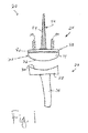
- Fig. 1 shows a wrist prosthesis 20 which includes a radial or proximal component generally designated 22 and a carpal or distal component, generally designated 24.
- the proximal component 22 is configured, adapted and/or operative to be implanted into a radius of a patient.
- the distal component 24 is configured, adapted and/or operative to be implanted into carpals of the patient.
- the proximal component 22 includes a stem 26 that is implanted into the radius of the patient. Situated on the stem 26 is a platform 28 that includes a curved or arcuate surface 30.
- the curved surface 30 provides a bearing surface for the distal component 24. Particularly, the curved surface 30 provides an articulation surface for the distal component 24 to articulate thereon.
- the proximal component 22 is manufactured from a material such as metal suitable for implantation, or various materials suitable for implantation with a plastic (e.g. polyethylene) insert (not shown) within the platform 28 to provide an articulating surface.
- the distal component 24 includes a head, head portion, head component or the like generally designated 32, a fixation plate generally designated 38, and an anchor or stem generally designated 42.
- the anchor 42 may constitute a stem as shown in Fig. 1 or may be a bone screw, or the other type of anchoring device. Shown in Fig. 1, and described below, are two bone screws 80 that extend from the fixation plate 38. The bone screws 80 are configured to be anchored into the carpus of the patient.
- the head 32 may or may not be rotatable with respect to the fixation plate 38.
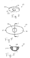
- the head 32 is shown in greater detail.
- the head 32 is preferably made from a metal such as cobalt-chrome but other materials suitable for implantation and providing a bearing or articulation surface are acceptable.
- the head 32 is defined by a body 34 that is generally egg-shaped (ovoid or the like) cut along its longitudinal axis.
- the body 34 defines an outer surface 36 that provides an arcuate or curved bearing surface.
- the arcuate shape of the outer surface 36 matches the arcuate shape of the bearing surface 30 of the platform 28 of the proximal component 22. In this manner, the head 32 can essentially congruently bear against and articulate with respect to the proximal component 22.
- the head 32 also has a bottom surface 46 that is preferably essentially flat. Since the head is ovoid-shaped, the bottom surface 46 essentially defines an ellipse. Disposed at the centre of the bottom surface 46 is a recess, bore, hole, or the like 48. As discussed further below, the recess 48 is configured to receive or be received on a boss, protuberance, or the like.
- the fixation plate 38 is defined by a body 40 that is generally shaped as an ovoid, ellipse, or the like.
- the shape of the body 40 generally corresponds to the shape of the bottom 46 of the head 32.
- the body 40 has a bottom surface 41, a first hole 54 at one oblong end of the body 40 and a second hole 56 on another oblong end of the body 40. It should be appreciated that the terms first and second are arbitrary and thus may be interchanged without consequence.
- the body further includes a third hole 62 that may be slightly off centre from a centre point of the body 40. A small height rim 51 extends about the hole 62 from the bottom surface 41.
- the body 40 has a top surface 43 through which the holes 54 and 56 extend. Extending from the top surface 43 around hole 52 is a large height rim 50.
- the rim 50 defines a boss that is configured, adapted, and/or operative to receive the recess 48 of the head 32.
- the rim 50 may be configured to allow the surface 46 of the head 32 to touch the surface 43 of the fixation plate 38 or may be configured to allow the surface 46 of the head 32 to be immediately adjacent but not touching the surface 43 of the fixation plate.
- the surfaces 46 and 43 touch the head 32 is rotatable with respect to the fixation plate 38, and when the surfaces 46 and 43 do not touch, the head 32 is not rotatable with respect to the fixation plate 38. This, however, may not be the case.
- the holes 54 and 56 are adapted to receive bushings therein, the bushings of which are described below.
- the bore 52 is adapted to receive the stem 42 and the set screw 96.
- the bore 52 is defined by three diameter bores. More particularly, the bore 52 has a first diameter bore 61 opening onto the surface 43, a second diameter bore 62 opening onto the surface 41, and a third diameter bore 60 connecting the first and second diameter bores 61 and 62.
- the third diameter bore 60 is smaller than the first and second diameter bores 61 and 62.
- the second diameter bore 62 is slightly tapered. This is to receive the tapered end 90 of the stem body 44 when a stem is used as the centre anchor.
- the first diameter is shown as a constant diameter bore.
- the bore 61 is sized to receive the head 100 of the set screw 96 or other like fastener if one is used (see Figs. 14-15).
- the bore 60 is sized to allow the shank 98 of the set screw 96 to extend through it but not the head 100.
- the stem end 90 is received in the bore 62 while the shank 98 is threadedly received in the threaded bore 92 of the end 90 of the stem 42.
- other bore configurations may be utilized such as oppositely tapered bores that connect, a single one diameter bore, all depending on the main or centre anchor and the manner in which the centre anchor is affixed to the fixation plate 38.
- the boss of the plate is positioned centrally with respect to the medial/lateral direction and offset slightly dorsally in the anterior/posterior direction.
- the outer diameter of this boss has a precisely machined Morse taper designed to firmly engage an articulating surface proximally, and a flat surface distally, that roughly simulates a football sliced along its long axis.
- the articulating surface is designed such that is mates with certain existing radial component articulating surfaces.
- the exemplary bone screw 80 is utilized to fix the fixation plate 38 to the carpus of a hand.
- the bone screw 80 has a body 82 that has a plurality of radially expanded threads extending from a rounded tip 84 to an end 86.
- the end 86 is threaded with typical, smaller threads.
- the threads 86 may be straight or may be tapered depending on the configuration of the internal threads of the bushing (see below).
- An exemplary bone screw that may be used is described in further detail in US-5954722.
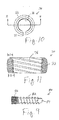
- the bushing 70 is defined by a generally annular or ring-shaped body 72 that includes a gap 74.
- the gap 74 allows the bushing to radially compress when inserted into the bores 54 and 56. This provides a press fit to retain the bushing 70 within the respective bore.
- the bushing 70 includes internal threads 76 that correspond to the threads of the end 86 of the bone screw 80. In one form, the threads 76 of the bushing 70 taper with respect to one end to the other end. This is illustrated by the distances d and D in Fig. 11. When d is smaller than D (i.e. d ⁇ D) there is a taper from the axial ends.
- the two bone screws 80 are peripherally attached to the fixation plate 38 through the use of the particularly designed bushings 70.
- the bushings 70 allow the trajectory of the bone screws 80 to be locked relative to the fixation plate 38.
- the two peripheral bores 54 and 56 of the fixation plate 38 are machined with an internal diameter that is preferably at least partially spherical in shape.
- the bushings 70 have a substantially mating spherical outer diameter (e.g. different radii) that is press fit into the bores 54 and 56 of the fixation plate 38 such that the bushings 70 may articulate within the bores 54 and 56 of the fixation plate 38.
- each bushing 70 also contains internal threads 76 that are preferably tapered in diameter from largest at a proximal end ("d") of the bushing and smallest at a distal end (“D"). These threads 76 accept the bone screw end 86 that has mating tapered threads such that when the bone screw 80 is firmly engaged into the bushing 70, the bushing 70 is radially loaded. This radial load locks the trajectory of the bone screw at moments consistent with the amount of friction between the bushing 70 and the fixation plate 38.
- the bone screws 80 mate with the bushings 70. It should be appreciated that various combinations of threads, tapers, no tapers, and the like with respect to both the bone screws and the bushings can be made.
- the stem 42 when used, functions as an anchor into the carpus, metacarpal and or bone of a finger.
- the stem is defined by a fluted and tapered body 44 that essentially forms a spike.
- the stem 44 has a neck 90 that may be tapered opposite to the taper of the body 44.
- a bore 92 that may be threaded as shown, is disposed at the end of the neck 90.
- the bore 92 is adapted to receive a pin (threaded or not depending on whether or not the bore 92 is threaded.
- the tapered portion of the body 44 includes a hollow 94. It should be appreciated that more or less flutes than that shown may be provided on the stem. The stem flutes aid in anchoring the stem 44 against torsion.
- the set screw 96 has a shank 98 that is threaded and a head 100.
- the head 100 includes a bore 102 that is configured to accept a driver for setting the set screw 96.
- the bore 102 may be configured as a hex, octagon, star, or the like.
- the threads of the shank 98 are complementary with the threads of the threaded bore 92 of the stem 42. While the set screw 96 is shown threaded, the set screw may not be threaded, depending on the type of fit or joining of the stem 42 and the fixation plate 38.
- Fig. 2 depicts the distal component 24 in an exploded view to better illustrate the various constituent components thereof described above.
- the fixation plate 38 provides a base upon which the various components are or may be assembled.
- the stem 42 central anchor
- the stem 42 may be affixed to the fixation plate 38 via the set screw 96 (or other fastener) that is inserted into the bore 52 from the other side (from surface 43) of the fixation plate 38.
- a bushing 70 is press fit into each bore 54 and 56. Thereafter, a bone screw 80 is inserted through each bushing 70. As the tip 84 of each bone screw, then the shank 82 is received in a carpal (bone), the threaded end 86 is threadedly received by the threads 76 of the bushing 70. The bone screws are installed until the end of the end 86 is flush or below the surface 43. During this time, the fixation plate 38 is preferably held in place. Thereafter, the head 32 is placed onto the fixation plate 38. Particularly, the recess 48 of the head 32 is received onto the boss 50 either loosely or by a press fit.
- the entire construct constituting an exemplary distal component 24 in accordance with the principles of the subject invention is shown in cross-section in Fig. 16.
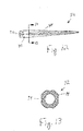
- a wrist prosthesis generally designated 20a.
- the wrist prosthesis includes a radial or proximal component generally designated 22 and a distal wrist component generally designated 24a. It should be appreciated that the components of the wrist prosthesis 20a and particularly the distal wrist component 24a that are different from the distal wrist component 24 are designated with an "a”.
- the distal wrist component 24a is generally the same as that described above with the exception of the central anchor.
- the central anchor is a bone screw 150 here shown as larger than the bone screws 80. It should be appreciated, though, that the bone screw 150 may be the same size as the bone screws 80 or may be smaller. In the case of a central bone screw 150, the bore 52 (not seen in Fig. 17) of the fixation plate 38 would be adapted to receive the bone screw 150.
- the central anchor may be different depending on circumstances.
- the distal wrist component does not have a central anchor.
- various combinations are contemplated.
- the subject distal wrist component provides a screw and bushing locking mechanism that provides a firmly positioned trajectory. This may lead to firmer carpal complex in the short term, thereby leading to higher probability of carpal fusion.
- the modular central stem attachment allows for varying shapes, lengths and/or sizes of central stems.
- the modular articulating head allows for varying shapes, heights, and/or forms of attachments. These can vary with patient indications and/or mating radial components.
- the modular head allows the application of a mobile bearing concept in an embodiment where the hole in the head does not lock onto a boss on the plate. As a final example, the offset nature of the hole pattern in the plate more accurately matches anatomy, allows better placement of screw centres, and provides the potential of superior fusion performance.
Landscapes
- Health & Medical Sciences (AREA)
- Orthopedic Medicine & Surgery (AREA)
- Cardiology (AREA)
- Oral & Maxillofacial Surgery (AREA)
- Transplantation (AREA)
- Engineering & Computer Science (AREA)
- Biomedical Technology (AREA)
- Heart & Thoracic Surgery (AREA)
- Vascular Medicine (AREA)
- Life Sciences & Earth Sciences (AREA)
- Animal Behavior & Ethology (AREA)
- General Health & Medical Sciences (AREA)
- Public Health (AREA)
- Veterinary Medicine (AREA)
- Prostheses (AREA)
Abstract
Description
Claims (12)
- A distal wrist component for a wrist prosthesis comprising:a fixation plate having a middle bore, two side bores, and a boss;a bushing disposed in said two side bores, each said bushing configured to receive a bone screw such that an end of the bone screw is flush with a surface of said fixation plate; anda head received on said boss.
- The distal wrist component of claim 1, wherein said boss is disposed about said middle bore.
- The distal wrist component of claim 1, wherein said fixation plate is ovoid.
- The distal wrist component of claim 3, wherein said boss is positioned centrally with respect to a medial/lateral direction and offset slightly dorsally in an anterior/posterior direction.
- The distal wrist component of claim 1, wherein each said bushing has internal threads.
- The distal wrist component of claim 5, wherein said internal threads of said bushing are tapered.
- The distal wrist component of claim 6, wherein said internal threads are tapered from a larger diameter at a proximal end thereof to a smaller diameter at a distal end thereof.
- The distal wrist component of claim 1, further comprising an anchor disposed in said middle bore.
- The distal wrist component of claim 1, in which the first and second bores have a spheric inner surface.
- The distal wrist component of claim 9, in which the bushing has a spheric outer diameter which matches the spheric inner surface of the first and second side bores, so that the bushings can articulate within the first and second side bores.
- The distal wrist component of claim 1, in which the boss extends from a surface of the fixation plate, about the middle bore.
- The distal wrist component of claim 1, in which the bushing is radially loaded to lock a trajectory of the bone screw at moments consistent with an amount of friction between said bushing and said fixation plate.
Applications Claiming Priority (4)
| Application Number | Priority Date | Filing Date | Title |
|---|---|---|---|
| US368740 | 1989-06-20 | ||
| US36874002P | 2002-03-29 | 2002-03-29 | |
| US10/396,644 US6890358B2 (en) | 2002-03-29 | 2003-03-25 | Distal component for wrist prosthesis |
| US396644 | 2003-03-25 |
Publications (3)
| Publication Number | Publication Date |
|---|---|
| EP1352622A2 true EP1352622A2 (en) | 2003-10-15 |
| EP1352622A3 EP1352622A3 (en) | 2004-01-21 |
| EP1352622B1 EP1352622B1 (en) | 2005-11-23 |
Family
ID=34555394
Family Applications (1)
| Application Number | Title | Priority Date | Filing Date |
|---|---|---|---|
| EP03252008A Expired - Lifetime EP1352622B1 (en) | 2002-03-29 | 2003-03-29 | Distal component for wrist prosthesis |
Country Status (6)
| Country | Link |
|---|---|
| US (1) | US6890358B2 (en) |
| EP (1) | EP1352622B1 (en) |
| JP (1) | JP4361305B2 (en) |
| AT (1) | ATE310474T1 (en) |
| AU (1) | AU2003203556B2 (en) |
| DE (1) | DE60302381T2 (en) |
Cited By (3)
| Publication number | Priority date | Publication date | Assignee | Title |
|---|---|---|---|---|
| EP1574184A1 (en) * | 2004-03-09 | 2005-09-14 | Zimmer Technology, Inc. | Tibial implant with a through post |
| CN100488470C (en) * | 2003-02-05 | 2009-05-20 | 瑞特医疗技术公司 | Articulating implant system |
| US8092545B2 (en) | 2002-02-20 | 2012-01-10 | Zimmer, Inc. | Knee arthroplasty prosthesis method |
Families Citing this family (80)
| Publication number | Priority date | Publication date | Assignee | Title |
|---|---|---|---|---|
| US8795379B2 (en) | 2001-07-11 | 2014-08-05 | Biomet Manufacturing, Llc | Variable prosthesis |
| US6942699B2 (en) | 2001-07-11 | 2005-09-13 | Biomet, Inc. | Shoulder prosthesis |
| US8062376B2 (en) * | 2002-07-10 | 2011-11-22 | Biomet Manufacturing Corp. | Shoulder implant assembly |
| EP1542602B1 (en) * | 2002-07-22 | 2010-11-17 | Acumed LLC | Bone fusion system |
| EP1581143B1 (en) * | 2002-09-18 | 2008-12-24 | Integra LifeSciences Corporation | Wrist implant apparatus |
| US8105390B2 (en) | 2002-10-24 | 2012-01-31 | Biomet Manufacturing Corp. | Method and apparatus for wrist arthroplasty |
| US8821581B2 (en) * | 2002-10-24 | 2014-09-02 | Biomet Manufacturing, Llc | Method and apparatus for wrist arthroplasty |
| US8940055B2 (en) | 2002-10-24 | 2015-01-27 | Biomet Manufacturing, Llc | Method and apparatus for wrist arthroplasty |
| US8372154B2 (en) * | 2002-10-24 | 2013-02-12 | Biomet Manufacturing Corp. | Method and apparatus for wrist arthroplasty |
| US8066777B2 (en) * | 2002-10-24 | 2011-11-29 | Biomet Manufacturing Corp. | Method and apparatus for wrist arthroplasty |
| US8105388B2 (en) * | 2002-10-24 | 2012-01-31 | Biomet Manufacturing Corp. | Method and apparatus for wrist arthroplasty |
| US6746486B1 (en) * | 2002-10-24 | 2004-06-08 | Biomet, Inc. | Method and apparatus for total wrist angled back carpal plate |
| US8052756B2 (en) | 2002-10-24 | 2011-11-08 | Biomet Manufacturing Corp. | Method and apparatus for wrist arthroplasty |
| US8105389B2 (en) * | 2002-10-24 | 2012-01-31 | Biomet Manufacturing Corp. | Method and apparatus for wrist arthroplasty |
| US7887544B2 (en) * | 2003-03-10 | 2011-02-15 | Tornier Sas | Ancillary tool for positioning a glenoid implant |
| US7625408B2 (en) * | 2003-07-22 | 2009-12-01 | Avanta Orthopaedics, Llc | Prosthetic wrist implant |
| FR2859099B1 (en) * | 2003-08-25 | 2006-01-06 | Tornier Sa | GLENOIDAL COMPONENT OF SHOULDER PROSTHESIS AND TOTAL SHOULDER PROSTHESIS INCORPORATING SUCH COMPONENT |
| US7534270B2 (en) * | 2003-09-03 | 2009-05-19 | Integra Lifesciences Corporation | Modular total ankle prosthesis apparatuses and methods |
| US8070820B2 (en) | 2003-10-08 | 2011-12-06 | Biomet Manufacturing Corp. | Shoulder implant assembly |
| FR2863865B1 (en) * | 2003-12-19 | 2006-10-06 | Tornier Sa | SHOULDER OR HIP PROSTHESIS AND METHOD OF MOUNTING |
| US20060161260A1 (en) * | 2003-12-23 | 2006-07-20 | Gareth Thomas | Total wrist prosthesis |
| US7963981B2 (en) | 2004-04-19 | 2011-06-21 | Globus Medical, Inc. | Bone fixation plate |
| US8236034B2 (en) | 2004-04-19 | 2012-08-07 | Globus Medical, Inc. | Bone fixation plate |
| EP1607069B1 (en) * | 2004-06-15 | 2009-12-23 | Tornier | Inverse-type total shoulder prosthesis |
| FR2871371B1 (en) * | 2004-06-15 | 2007-04-06 | Tornier Sas | GLENOIDAL COMPONENT OF SHOULDER PROSTHESIS, SET OF COMPONENT ELEMENTS OF SUCH COMPONENT AND TOTAL SHOULDER PROSTHESIS INCORPORATING SUCH COMPONENT |
| US8303665B2 (en) | 2004-06-15 | 2012-11-06 | Tornier Sas | Glenoidal component, set of such components and shoulder prosthesis incorporating such a glenoidal component |
| FR2872025B1 (en) | 2004-06-28 | 2006-08-25 | Tornier Sas | PROSTHESIS OF SHOULDER OR HIP |
| US7160331B2 (en) | 2004-12-01 | 2007-01-09 | Mayo Foundation For Medical Research And Education | Sigmoid notch implant |
| US7682362B2 (en) * | 2005-02-01 | 2010-03-23 | Smith & Nephew, Inc. | Lockable orientation stylus |
| US8562689B2 (en) * | 2005-10-13 | 2013-10-22 | Aptis Medical, Llc | Wrist prosthesis |
| FR2893247B1 (en) * | 2005-11-17 | 2008-08-29 | Bioprofile Sa | IMPLANT, PARTICULARLY PARTIAL IMPLANT OF THE HEAD OF CUBITUS |
| EP1981439A4 (en) * | 2006-01-20 | 2013-02-06 | Gmbh Synthes | Method of preparing an ankle joint for replacement, joint prosthesis, and cutting alignment apparatus for use in performing an arthroplasty procedure |
| US7753959B2 (en) * | 2006-03-20 | 2010-07-13 | Biomet Manufacturing Corp. | Modular center pegged glenoid |
| US8425614B2 (en) * | 2006-03-20 | 2013-04-23 | Biomet Manufacturing Corp. | Modular center pegged glenoid |
| EP1996125B1 (en) * | 2006-03-21 | 2013-05-15 | Tornier, Inc. | Glenoid component with improved fixation stability |
| WO2007109291A2 (en) * | 2006-03-21 | 2007-09-27 | Axiom Orthopaedics, Inc. | Non-spherical articulating surfaces in shoulder and hip prosthesis |
| US20070225821A1 (en) * | 2006-03-21 | 2007-09-27 | Axiom Orthopaedics, Inc. | Femoral and humeral stem geometry and implantation method for orthopedic joint reconstruction |
| FR2899790B1 (en) * | 2006-04-13 | 2008-06-13 | Tornier Sas | GLENOIDAL COMPONENT FOR TOTAL SHOULDER PROSTHESIS, SET OF SUCH COMPONENTS, AND TOTAL SHOULDER PROSTHESIS COMPRISING SUCH A COMPONENT |
| FR2900045B1 (en) | 2006-04-21 | 2009-01-16 | Tornier Sas | PROSTHESIS OF SHOULDER OR HIP |
| FR2911773B1 (en) * | 2007-01-30 | 2009-03-27 | Tornier Sas | METHOD AND ASSEMBLY OF SURGICAL INSTRUMENTATION FOR POSITIONING A TOTAL REVERSE SHOULDER PROSTHESIS, AND CORRESPONDING PROSTHESIS |
| US20090287309A1 (en) | 2007-01-30 | 2009-11-19 | Tornier Sas | Intra-articular joint replacement |
| US20100131069A1 (en) * | 2007-08-01 | 2010-05-27 | Jeffrey Halbrecht | Method and system for patella tendon realignment |
| WO2009018365A1 (en) * | 2007-08-01 | 2009-02-05 | Jeffrey Halbrecht | Method and system for patella tendon realignment |
| US20090105840A1 (en) * | 2007-10-18 | 2009-04-23 | Inbone Technologies, Inc. | Fibular stiffener and bony defect replacer |
| DE602007007095D1 (en) * | 2007-11-07 | 2010-07-22 | Gs Dev Ab | Artificial joint |
| US8052755B2 (en) | 2008-05-09 | 2011-11-08 | Remi Sciences, Inc. | Ulnar head prosthesis system |
| US7875082B2 (en) | 2008-05-09 | 2011-01-25 | Remi Sciences, Inc. | Ulnar head prosthesis system |
| US8167952B2 (en) * | 2008-09-03 | 2012-05-01 | The Cleveland Clinic Foundation | Arthroplastic implant with shield for basilar joint and related methods |
| US8343228B2 (en) * | 2008-09-03 | 2013-01-01 | The Cleveland Clinic Foundation | Arthroplastic implant with anchor peg for basilar joint and related methods |
| US9861408B2 (en) | 2009-08-27 | 2018-01-09 | The Foundry, Llc | Method and apparatus for treating canine cruciate ligament disease |
| US10349980B2 (en) | 2009-08-27 | 2019-07-16 | The Foundry, Llc | Method and apparatus for altering biomechanics of the shoulder |
| US9668868B2 (en) | 2009-08-27 | 2017-06-06 | Cotera, Inc. | Apparatus and methods for treatment of patellofemoral conditions |
| CA2771332C (en) | 2009-08-27 | 2020-11-10 | Cotera, Inc. | Method and apparatus for force redistribution in articular joints |
| US9278004B2 (en) | 2009-08-27 | 2016-03-08 | Cotera, Inc. | Method and apparatus for altering biomechanics of the articular joints |
| US9512445B2 (en) | 2009-08-31 | 2016-12-06 | The Cleveland Clinic Foundation | Humeral joint replacement component |
| US8152854B2 (en) * | 2009-09-30 | 2012-04-10 | Imbriglia Joseph E | Resurfacing implant for the wrist and method of implantation thereof |
| US9408652B2 (en) | 2010-04-27 | 2016-08-09 | Tornier Sas | Intra-articular joint replacement and method |
| FR2966343B1 (en) | 2010-10-22 | 2012-12-07 | Tornier Sa | SET OF GLENOIDIAN COMPONENTS OF SHOULDER PROSTHESIS |
| AU2012253444B2 (en) * | 2011-05-12 | 2016-02-18 | Howmedica Osteonics Corp. | Wrist implant for carpal hemiarthroplasty |
| US8506638B2 (en) | 2011-07-13 | 2013-08-13 | Biomets Manufacturing, LLC | Shoulder prosthesis |
| US20130018476A1 (en) | 2011-07-13 | 2013-01-17 | Biomet Manufacturing Corp. | Shoulder prosthesis |
| US8702804B2 (en) | 2011-12-02 | 2014-04-22 | Biomet Manufacturing, Llc | Variable prosthesis |
| US9421106B2 (en) | 2011-12-07 | 2016-08-23 | Howmedica Osteonics Corp. | Reverse shoulder baseplate with alignment guide for glenosphere |
| US8663334B2 (en) | 2012-05-31 | 2014-03-04 | Howmedica Osteonics Corp. | Lateral entry insert for cup trial |
| US8906102B2 (en) | 2012-05-31 | 2014-12-09 | Howmedica Osteonics Corp. | Lateral entry insert for cup trial |
| US9468466B1 (en) | 2012-08-24 | 2016-10-18 | Cotera, Inc. | Method and apparatus for altering biomechanics of the spine |
| US9744044B2 (en) * | 2013-03-15 | 2017-08-29 | Mako Surgical Corp. | Unicondylar tibial knee implant |
| EP4201349B1 (en) * | 2014-08-22 | 2025-09-10 | Wright Medical Technology, Inc. | Talar revision implant |
| US10390972B2 (en) | 2016-01-15 | 2019-08-27 | Howmedica Osteonics Corp. | Humeral trial adaptor |
| WO2017165727A2 (en) * | 2016-03-24 | 2017-09-28 | Skeletal Dynamics, Llc | Total wrist prosthesis and related methods |
| US10113323B2 (en) * | 2016-10-31 | 2018-10-30 | Stego Industries, LLC | Concrete forming stake apparatus |
| US10864082B2 (en) * | 2018-10-19 | 2020-12-15 | Roy D. Bloebaum | Osteolysis-resistant cementless joint implant with improved stability and seating function |
| CN110840634A (en) * | 2019-11-25 | 2020-02-28 | 北京爱康宜诚医疗器材有限公司 | wrist prosthesis |
| USD930834S1 (en) * | 2019-12-10 | 2021-09-14 | David Scott Nutter | Anatomic great toe joint |
| EP4084711A4 (en) | 2020-01-02 | 2024-01-03 | ZKR Orthopedics, Inc. | IMPLANT FOR REALIGNING THE PATELLA TENDON WITH A CHANGABLE SHAPE |
| AU2021200854A1 (en) | 2020-03-03 | 2021-09-16 | Howmedica Osteonics Corp. | Glenoid implant with additively manufactured fixation posts |
| WO2021231253A1 (en) | 2020-05-11 | 2021-11-18 | Zkr Orthopedics, Inc. | Adjustable patellar tendon realignment implant |
| WO2022060853A1 (en) * | 2020-09-15 | 2022-03-24 | New York Society For The Relief Of The Ruptured And Crippled, Maintaining The Hospital For Special Surgery | Total arthroplasty of the carpometacarpal joint |
| CN116077242B (en) * | 2023-01-18 | 2025-08-19 | 大连大学附属中山医院 | Gradual change porous structure tantalum metal wrist joint prosthesis with wear-resisting layer |
| AU2024334108A1 (en) | 2023-08-29 | 2026-02-26 | Zkr Orthopedics, Inc. | Multiplanar tendon realignment implants and related systems and methods |
Family Cites Families (17)
| Publication number | Priority date | Publication date | Assignee | Title |
|---|---|---|---|---|
| US4259752A (en) * | 1980-01-04 | 1981-04-07 | Julio Taleisnik | Endoprosthetic wrist joint |
| US4784661A (en) * | 1985-11-22 | 1988-11-15 | Robert Beckenbaugh | Total wrist prosthesis |
| US5019103A (en) * | 1990-02-05 | 1991-05-28 | Boehringer Mannheim Corporation | Tibial wedge system |
| FR2681240A1 (en) * | 1991-09-12 | 1993-03-19 | Tornier Sa | TOTAL WRIST PROSTHESIS. |
| CA2078840C (en) * | 1991-09-24 | 1998-08-11 | Alan J. Yeadon | Wrist prothesis |
| ATE181497T1 (en) * | 1993-01-21 | 1999-07-15 | Sulzer Orthopaedie Ag | ARTIFICIAL WRIST |
| DE4406090A1 (en) * | 1994-02-24 | 1995-08-31 | Plus Endoprothetik Ag | Prosthetic wrist |
| ATE204449T1 (en) * | 1995-06-21 | 2001-09-15 | Sulzer Orthopaedie Ag | ARTIFICIAL WRIST |
| US5702470A (en) * | 1996-02-23 | 1997-12-30 | Kinetikos Medical Incorporated | Prosthetic wrist implant and related method of implantation |
| CN1216456A (en) * | 1996-02-29 | 1999-05-12 | 阿米特·埃吉 | Prosthetic systems for anatomical replacement in the hand and wrist |
| FR2750037B1 (en) * | 1996-06-25 | 1998-11-27 | Tornier Sa | MONOBLOCK SHOULDER PROSTHESIS |
| DE29705500U1 (en) * | 1997-03-26 | 1998-07-23 | Waldemar Link GmbH & Co, 22339 Hamburg | Hip prosthesis |
| US5954722A (en) * | 1997-07-29 | 1999-09-21 | Depuy Acromed, Inc. | Polyaxial locking plate |
| DE29722973U1 (en) * | 1997-12-30 | 1999-03-25 | Thabe, Heiner, Dr.med., 55543 Bad Kreuznach | Prosthetic wrist |
| US6086614A (en) * | 1998-01-23 | 2000-07-11 | Sulzer Orthopedics Inc. | Orthopedic prosthesis having anti-backout screw |
| DE19820015C2 (en) * | 1998-05-06 | 2000-09-07 | Schaefer Micomed Gmbh | Prosthetic wrist |
| FR2802799B1 (en) * | 1999-12-23 | 2002-08-16 | Depuy France | SHOULDER PROSTHESIS KIT |
-
2003
- 2003-03-25 US US10/396,644 patent/US6890358B2/en not_active Expired - Fee Related
- 2003-03-28 AU AU2003203556A patent/AU2003203556B2/en not_active Ceased
- 2003-03-29 DE DE60302381T patent/DE60302381T2/en not_active Expired - Lifetime
- 2003-03-29 AT AT03252008T patent/ATE310474T1/en not_active IP Right Cessation
- 2003-03-29 EP EP03252008A patent/EP1352622B1/en not_active Expired - Lifetime
- 2003-03-31 JP JP2003096034A patent/JP4361305B2/en not_active Expired - Fee Related
Cited By (4)
| Publication number | Priority date | Publication date | Assignee | Title |
|---|---|---|---|---|
| US8092545B2 (en) | 2002-02-20 | 2012-01-10 | Zimmer, Inc. | Knee arthroplasty prosthesis method |
| US9072605B2 (en) | 2002-02-20 | 2015-07-07 | Zimmer, Inc. | Knee arthroplasty prosthesis |
| CN100488470C (en) * | 2003-02-05 | 2009-05-20 | 瑞特医疗技术公司 | Articulating implant system |
| EP1574184A1 (en) * | 2004-03-09 | 2005-09-14 | Zimmer Technology, Inc. | Tibial implant with a through post |
Also Published As
| Publication number | Publication date |
|---|---|
| US20030216813A1 (en) | 2003-11-20 |
| JP2004000534A (en) | 2004-01-08 |
| AU2003203556B2 (en) | 2008-10-23 |
| JP4361305B2 (en) | 2009-11-11 |
| EP1352622A3 (en) | 2004-01-21 |
| ATE310474T1 (en) | 2005-12-15 |
| EP1352622B1 (en) | 2005-11-23 |
| DE60302381D1 (en) | 2005-12-29 |
| AU2003203556A1 (en) | 2003-10-30 |
| DE60302381T2 (en) | 2006-07-27 |
| US6890358B2 (en) | 2005-05-10 |
Similar Documents
| Publication | Publication Date | Title |
|---|---|---|
| EP1352622B1 (en) | Distal component for wrist prosthesis | |
| US20250345180A1 (en) | Modular Rotational Device For Torsionally Stabilizing An Endoprosthesis | |
| US5458646A (en) | Wrist prosthesis | |
| US4106128A (en) | Endoprosthetic bone joint | |
| US8105388B2 (en) | Method and apparatus for wrist arthroplasty | |
| US9283083B2 (en) | Shoulder implant assembly | |
| US8821581B2 (en) | Method and apparatus for wrist arthroplasty | |
| US7766970B2 (en) | Method and apparatus for wrist arthroplasty | |
| CA1296138C (en) | Metatarsal-phalangeal replacement joint | |
| EP0736292B1 (en) | Prosthetic patella implant of the knee joint | |
| US8372154B2 (en) | Method and apparatus for wrist arthroplasty | |
| EP1350488A2 (en) | Wrist prosthesis | |
| EP1323395A2 (en) | Augmented glenoid component having an interrupted surface | |
| EP3914193B1 (en) | Bone joint implants | |
| CA2646995A1 (en) | Reverse shoulder prosthesis | |
| AU2006252164A1 (en) | Orthopaedic joint assembly with rigidly locked fastener, kit & associated method | |
| GB2269752A (en) | Anatomic wrist | |
| US11406507B2 (en) | Total wrist prosthesis and related methods | |
| US10772735B2 (en) | Distal radioulnar joint prosthesis and method of use | |
| CN118236210A (en) | Dislocation preventing device for constrained prosthetic knee | |
| NL2024112B1 (en) | Prosthesis for the movable coupling of the metacarpal bone I of one hand to a second hand bone and a combination of a prosthesis and a fastener | |
| CA2853437C (en) | Reverse shoulder prosthesis |
Legal Events
| Date | Code | Title | Description |
|---|---|---|---|
| PUAI | Public reference made under article 153(3) epc to a published international application that has entered the european phase |
Free format text: ORIGINAL CODE: 0009012 |
|
| AK | Designated contracting states |
Kind code of ref document: A2 Designated state(s): AT BE BG CH CY CZ DE DK EE ES FI FR GB GR HU IE IT LI LU MC NL PT RO SE SI SK TR |
|
| AX | Request for extension of the european patent |
Extension state: AL LT LV MK |
|
| PUAL | Search report despatched |
Free format text: ORIGINAL CODE: 0009013 |
|
| AK | Designated contracting states |
Kind code of ref document: A3 Designated state(s): AT BE BG CH CY CZ DE DK EE ES FI FR GB GR HU IE IT LI LU MC NL PT RO SE SI SK TR |
|
| AX | Request for extension of the european patent |
Extension state: AL LT LV MK |
|
| 17P | Request for examination filed |
Effective date: 20040705 |
|
| AKX | Designation fees paid |
Designated state(s): AT BE BG CH CY CZ DE DK EE ES FI FR GB GR HU IE IT LI LU MC NL PT RO SE SI SK TR |
|
| GRAP | Despatch of communication of intention to grant a patent |
Free format text: ORIGINAL CODE: EPIDOSNIGR1 |
|
| GRAS | Grant fee paid |
Free format text: ORIGINAL CODE: EPIDOSNIGR3 |
|
| GRAA | (expected) grant |
Free format text: ORIGINAL CODE: 0009210 |
|
| AK | Designated contracting states |
Kind code of ref document: B1 Designated state(s): AT BE BG CH CY CZ DE DK EE ES FI FR GB GR HU IE IT LI LU MC NL PT RO SE SI SK TR |
|
| PG25 | Lapsed in a contracting state [announced via postgrant information from national office to epo] |
Ref country code: SI Free format text: LAPSE BECAUSE OF FAILURE TO SUBMIT A TRANSLATION OF THE DESCRIPTION OR TO PAY THE FEE WITHIN THE PRESCRIBED TIME-LIMIT Effective date: 20051123 Ref country code: SK Free format text: LAPSE BECAUSE OF FAILURE TO SUBMIT A TRANSLATION OF THE DESCRIPTION OR TO PAY THE FEE WITHIN THE PRESCRIBED TIME-LIMIT Effective date: 20051123 Ref country code: AT Free format text: LAPSE BECAUSE OF FAILURE TO SUBMIT A TRANSLATION OF THE DESCRIPTION OR TO PAY THE FEE WITHIN THE PRESCRIBED TIME-LIMIT Effective date: 20051123 Ref country code: RO Free format text: LAPSE BECAUSE OF FAILURE TO SUBMIT A TRANSLATION OF THE DESCRIPTION OR TO PAY THE FEE WITHIN THE PRESCRIBED TIME-LIMIT Effective date: 20051123 Ref country code: CZ Free format text: LAPSE BECAUSE OF FAILURE TO SUBMIT A TRANSLATION OF THE DESCRIPTION OR TO PAY THE FEE WITHIN THE PRESCRIBED TIME-LIMIT Effective date: 20051123 Ref country code: FI Free format text: LAPSE BECAUSE OF FAILURE TO SUBMIT A TRANSLATION OF THE DESCRIPTION OR TO PAY THE FEE WITHIN THE PRESCRIBED TIME-LIMIT Effective date: 20051123 Ref country code: BE Free format text: LAPSE BECAUSE OF FAILURE TO SUBMIT A TRANSLATION OF THE DESCRIPTION OR TO PAY THE FEE WITHIN THE PRESCRIBED TIME-LIMIT Effective date: 20051123 Ref country code: NL Free format text: LAPSE BECAUSE OF FAILURE TO SUBMIT A TRANSLATION OF THE DESCRIPTION OR TO PAY THE FEE WITHIN THE PRESCRIBED TIME-LIMIT Effective date: 20051123 |
|
| REG | Reference to a national code |
Ref country code: GB Ref legal event code: FG4D |
|
| REG | Reference to a national code |
Ref country code: CH Ref legal event code: EP |
|
| REF | Corresponds to: |
Ref document number: 60302381 Country of ref document: DE Date of ref document: 20051229 Kind code of ref document: P |
|
| REG | Reference to a national code |
Ref country code: IE Ref legal event code: FG4D |
|
| REG | Reference to a national code |
Ref country code: CH Ref legal event code: NV Representative=s name: E. BLUM & CO. PATENTANWAELTE |
|
| PG25 | Lapsed in a contracting state [announced via postgrant information from national office to epo] |
Ref country code: BG Free format text: LAPSE BECAUSE OF FAILURE TO SUBMIT A TRANSLATION OF THE DESCRIPTION OR TO PAY THE FEE WITHIN THE PRESCRIBED TIME-LIMIT Effective date: 20060223 Ref country code: DK Free format text: LAPSE BECAUSE OF FAILURE TO SUBMIT A TRANSLATION OF THE DESCRIPTION OR TO PAY THE FEE WITHIN THE PRESCRIBED TIME-LIMIT Effective date: 20060223 Ref country code: GR Free format text: LAPSE BECAUSE OF FAILURE TO SUBMIT A TRANSLATION OF THE DESCRIPTION OR TO PAY THE FEE WITHIN THE PRESCRIBED TIME-LIMIT Effective date: 20060223 Ref country code: SE Free format text: LAPSE BECAUSE OF FAILURE TO SUBMIT A TRANSLATION OF THE DESCRIPTION OR TO PAY THE FEE WITHIN THE PRESCRIBED TIME-LIMIT Effective date: 20060223 |
|
| PG25 | Lapsed in a contracting state [announced via postgrant information from national office to epo] |
Ref country code: ES Free format text: LAPSE BECAUSE OF FAILURE TO SUBMIT A TRANSLATION OF THE DESCRIPTION OR TO PAY THE FEE WITHIN THE PRESCRIBED TIME-LIMIT Effective date: 20060306 |
|
| PG25 | Lapsed in a contracting state [announced via postgrant information from national office to epo] |
Ref country code: MC Free format text: LAPSE BECAUSE OF NON-PAYMENT OF DUE FEES Effective date: 20060331 Ref country code: LU Free format text: LAPSE BECAUSE OF NON-PAYMENT OF DUE FEES Effective date: 20060331 |
|
| PG25 | Lapsed in a contracting state [announced via postgrant information from national office to epo] |
Ref country code: PT Free format text: LAPSE BECAUSE OF FAILURE TO SUBMIT A TRANSLATION OF THE DESCRIPTION OR TO PAY THE FEE WITHIN THE PRESCRIBED TIME-LIMIT Effective date: 20060424 |
|
| NLV1 | Nl: lapsed or annulled due to failure to fulfill the requirements of art. 29p and 29m of the patents act | ||
| PG25 | Lapsed in a contracting state [announced via postgrant information from national office to epo] |
Ref country code: HU Free format text: LAPSE BECAUSE OF FAILURE TO SUBMIT A TRANSLATION OF THE DESCRIPTION OR TO PAY THE FEE WITHIN THE PRESCRIBED TIME-LIMIT Effective date: 20060524 |
|
| ET | Fr: translation filed | ||
| PLBE | No opposition filed within time limit |
Free format text: ORIGINAL CODE: 0009261 |
|
| STAA | Information on the status of an ep patent application or granted ep patent |
Free format text: STATUS: NO OPPOSITION FILED WITHIN TIME LIMIT |
|
| 26N | No opposition filed |
Effective date: 20060824 |
|
| REG | Reference to a national code |
Ref country code: CH Ref legal event code: PFA Owner name: DEPUY PRODUCTS, INC. Free format text: DEPUY PRODUCTS, INC.#700 ORTHOPAEDIC DRIVE#WARSAW, INDIANA 46581 (US) -TRANSFER TO- DEPUY PRODUCTS, INC.#700 ORTHOPAEDIC DRIVE#WARSAW, INDIANA 46581 (US) |
|
| PG25 | Lapsed in a contracting state [announced via postgrant information from national office to epo] |
Ref country code: EE Free format text: LAPSE BECAUSE OF FAILURE TO SUBMIT A TRANSLATION OF THE DESCRIPTION OR TO PAY THE FEE WITHIN THE PRESCRIBED TIME-LIMIT Effective date: 20051123 |
|
| PG25 | Lapsed in a contracting state [announced via postgrant information from national office to epo] |
Ref country code: TR Free format text: LAPSE BECAUSE OF FAILURE TO SUBMIT A TRANSLATION OF THE DESCRIPTION OR TO PAY THE FEE WITHIN THE PRESCRIBED TIME-LIMIT Effective date: 20051123 |
|
| PG25 | Lapsed in a contracting state [announced via postgrant information from national office to epo] |
Ref country code: CY Free format text: LAPSE BECAUSE OF FAILURE TO SUBMIT A TRANSLATION OF THE DESCRIPTION OR TO PAY THE FEE WITHIN THE PRESCRIBED TIME-LIMIT Effective date: 20051123 |
|
| PGFP | Annual fee paid to national office [announced via postgrant information from national office to epo] |
Ref country code: IE Payment date: 20110310 Year of fee payment: 9 |
|
| PGFP | Annual fee paid to national office [announced via postgrant information from national office to epo] |
Ref country code: IT Payment date: 20110328 Year of fee payment: 9 Ref country code: FR Payment date: 20110317 Year of fee payment: 9 Ref country code: CH Payment date: 20110314 Year of fee payment: 9 |
|
| PGFP | Annual fee paid to national office [announced via postgrant information from national office to epo] |
Ref country code: DE Payment date: 20110323 Year of fee payment: 9 Ref country code: GB Payment date: 20110323 Year of fee payment: 9 |
|
| REG | Reference to a national code |
Ref country code: CH Ref legal event code: PL |
|
| GBPC | Gb: european patent ceased through non-payment of renewal fee |
Effective date: 20120329 |
|
| REG | Reference to a national code |
Ref country code: FR Ref legal event code: ST Effective date: 20121130 |
|
| REG | Reference to a national code |
Ref country code: IE Ref legal event code: MM4A |
|
| PG25 | Lapsed in a contracting state [announced via postgrant information from national office to epo] |
Ref country code: LI Free format text: LAPSE BECAUSE OF NON-PAYMENT OF DUE FEES Effective date: 20120331 Ref country code: GB Free format text: LAPSE BECAUSE OF NON-PAYMENT OF DUE FEES Effective date: 20120329 Ref country code: FR Free format text: LAPSE BECAUSE OF NON-PAYMENT OF DUE FEES Effective date: 20120402 Ref country code: IE Free format text: LAPSE BECAUSE OF NON-PAYMENT OF DUE FEES Effective date: 20120329 Ref country code: CH Free format text: LAPSE BECAUSE OF NON-PAYMENT OF DUE FEES Effective date: 20120331 |
|
| REG | Reference to a national code |
Ref country code: DE Ref legal event code: R119 Ref document number: 60302381 Country of ref document: DE Effective date: 20121002 |
|
| PG25 | Lapsed in a contracting state [announced via postgrant information from national office to epo] |
Ref country code: IT Free format text: LAPSE BECAUSE OF NON-PAYMENT OF DUE FEES Effective date: 20120329 |
|
| PG25 | Lapsed in a contracting state [announced via postgrant information from national office to epo] |
Ref country code: DE Free format text: LAPSE BECAUSE OF NON-PAYMENT OF DUE FEES Effective date: 20121002 |