EP1351125A2 - Computer system having plural storage systems - Google Patents
Computer system having plural storage systems Download PDFInfo
- Publication number
- EP1351125A2 EP1351125A2 EP02019223A EP02019223A EP1351125A2 EP 1351125 A2 EP1351125 A2 EP 1351125A2 EP 02019223 A EP02019223 A EP 02019223A EP 02019223 A EP02019223 A EP 02019223A EP 1351125 A2 EP1351125 A2 EP 1351125A2
- Authority
- EP
- European Patent Office
- Prior art keywords
- virtualization
- data
- computer
- server
- information
- Prior art date
- Legal status (The legal status is an assumption and is not a legal conclusion. Google has not performed a legal analysis and makes no representation as to the accuracy of the status listed.)
- Withdrawn
Links
Images






Classifications
-
- G—PHYSICS
- G06—COMPUTING OR CALCULATING; COUNTING
- G06F—ELECTRIC DIGITAL DATA PROCESSING
- G06F3/00—Input arrangements for transferring data to be processed into a form capable of being handled by the computer; Output arrangements for transferring data from processing unit to output unit, e.g. interface arrangements
- G06F3/06—Digital input from, or digital output to, record carriers, e.g. RAID, emulated record carriers or networked record carriers
- G06F3/0601—Interfaces specially adapted for storage systems
- G06F3/0628—Interfaces specially adapted for storage systems making use of a particular technique
- G06F3/0662—Virtualisation aspects
- G06F3/0664—Virtualisation aspects at device level, e.g. emulation of a storage device or system
-
- G—PHYSICS
- G06—COMPUTING OR CALCULATING; COUNTING
- G06F—ELECTRIC DIGITAL DATA PROCESSING
- G06F3/00—Input arrangements for transferring data to be processed into a form capable of being handled by the computer; Output arrangements for transferring data from processing unit to output unit, e.g. interface arrangements
- G06F3/06—Digital input from, or digital output to, record carriers, e.g. RAID, emulated record carriers or networked record carriers
- G06F3/0601—Interfaces specially adapted for storage systems
- G06F3/0602—Interfaces specially adapted for storage systems specifically adapted to achieve a particular effect
- G06F3/0604—Improving or facilitating administration, e.g. storage management
- G06F3/0607—Improving or facilitating administration, e.g. storage management by facilitating the process of upgrading existing storage systems, e.g. for improving compatibility between host and storage device
-
- G—PHYSICS
- G06—COMPUTING OR CALCULATING; COUNTING
- G06F—ELECTRIC DIGITAL DATA PROCESSING
- G06F3/00—Input arrangements for transferring data to be processed into a form capable of being handled by the computer; Output arrangements for transferring data from processing unit to output unit, e.g. interface arrangements
- G06F3/06—Digital input from, or digital output to, record carriers, e.g. RAID, emulated record carriers or networked record carriers
- G06F3/0601—Interfaces specially adapted for storage systems
- G06F3/0602—Interfaces specially adapted for storage systems specifically adapted to achieve a particular effect
- G06F3/061—Improving I/O performance
- G06F3/0611—Improving I/O performance in relation to response time
-
- G—PHYSICS
- G06—COMPUTING OR CALCULATING; COUNTING
- G06F—ELECTRIC DIGITAL DATA PROCESSING
- G06F3/00—Input arrangements for transferring data to be processed into a form capable of being handled by the computer; Output arrangements for transferring data from processing unit to output unit, e.g. interface arrangements
- G06F3/06—Digital input from, or digital output to, record carriers, e.g. RAID, emulated record carriers or networked record carriers
- G06F3/0601—Interfaces specially adapted for storage systems
- G06F3/0668—Interfaces specially adapted for storage systems adopting a particular infrastructure
- G06F3/067—Distributed or networked storage systems, e.g. storage area networks [SAN], network attached storage [NAS]
-
- G—PHYSICS
- G06—COMPUTING OR CALCULATING; COUNTING
- G06F—ELECTRIC DIGITAL DATA PROCESSING
- G06F2206/00—Indexing scheme related to dedicated interfaces for computers
- G06F2206/10—Indexing scheme related to storage interfaces for computers, indexing schema related to group G06F3/06
- G06F2206/1012—Load balancing
Definitions
- the present invention relates to a computer system virtually managing or controlling storage areas of a plurality of storage systems as one logical storage area or a plurality of logical storage areas.
- a storage system is used to indicate a single storage such as a disk device and a set of "just bunch of disks (JBOD)" and a controller thereof as well as a set of a plurality of storages such as redundant array of inexpensive disks (RAID) and a controller thereof.
- JBOD just bunch of disks
- RAID redundant array of inexpensive disks
- the first approach provides a virtualization system in which a computer connected between a computer (to be called a server hereinbelow) using the storage system and the storage system manages or controls a correspondence between storage areas of the storage system and virtual volumes indicated to the server.
- a computer to be called a server hereinbelow
- the storage system manages or controls a correspondence between storage areas of the storage system and virtual volumes indicated to the server.
- the computer having received an access request to a virtual volume, the computer converts the request to an access request to a storage area of the storage system and issues the request to the storage system.
- the second approach provides a virtualization system including a virtualization or virtualizing computer, which controls a correspondence between storage areas of the storage system and an area of a virtual volume indicated to the user.
- a server issues an inquiry to the virtualization computer to obtain a position or an address of a storage area of a storage system corresponding to the virtual volume to be accessed.
- the virtualization computer sends an address in the storage area to the server according to information managed by the virtualization computer. Having received the address from the virtualization computer, the server accesses the area of the storage system using the address.
- the server must collaborate with the virtualization computer.
- it is necessary to prepare a collaborative function for the virtualization computer in association with many types of operating systems (OS) of servers.
- OS operating systems
- considerably many types of general operating systems are available in the present stage of art. It is therefore not practical to cope with all operating systems.
- the first approach is advantageous because it is not required to cope with the respective operating systems.
- the computer connected to the servers and the storage systems executes processing such as the address translation and the issuance of a request to a storage system.
- processing such as the address translation and the issuance of a request to a storage system.
- This leads to a problem that a limit of performance of the computer becomes a limit of performance of the system. For example, saving data from a storage system to another storage system imposes quite a heavy load on the computer. In this case, access performance of the overall system is also reduced. If the computer implementing the virtualization fails, the entire storage system cannot be used.
- Another object of the present invention is to provide a virtualization system capable of achieving desired performance in association with increase in the load imposed on the virtualization apparatus executing virtualization processing between a server and a storage system.
- Another object of the present invention is to provide a virtualization system in which even if the computer managing virtualization fails, input and output operations of data are not adversely influenced between a server and a storage system.
- the virtualization apparatus to conduct virtualization includes a switch (to be referred to as a virtualization switch hereinbelow) to execute virtualization processing and a computer (to be referred to as a virtualization server) to execute virtualization processing.
- the virtualization switch executes processing as follows.
- the switch receives data from the server to convert the data into data to be fed to a storage area of the storage system and transmits the data to the storage system.
- the virtualization switch converts the received data into data from a virtualized volume and sends the data to the server.
- the virtualization apparatus uses virtualization information, i.e., information of a correspondence between virtual volumes and storage areas of the storage system.
- the virtualization server receives, from the virtualization switch, data requiring predetermined processing, for example, data to be copied from a storage system onto another storage system.
- the server executes the predetermined processing and then sends the data to the server or an associated storage device.
- the virtualization device includes a plurality of virtualization servers and a plurality of virtualization switches
- when one of the switches or the servers fails it is possible that the processing of virtualization is taken over to, for example, another virtualization server.
- a configuration of a favorable embodiment of the present invention includes a computer for management (control server) which controls virtual information indicating a correspondence between storage areas of the storage system and virtual volumes and which also controls states of devices in the virtualization system.
- control server controls virtual information indicating a correspondence between storage areas of the storage system and virtual volumes and which also controls states of devices in the virtualization system.
- the control server issues an instruction to the virtualization apparatus to change an access path between the server and the storage system
- the virtualization apparatus allocates several ones of the virtual volumes as processing objects in a section of the virtualization apparatus to processing of devices with a lower processing load.
- a virtualization system in which the computer to conduct the virtualization does not become a processing bottleneck in the overall system. Moreover, according to the present invention, there is provided a virtualization system which achieves desired performance in association with increase in the processing load in a section executing the virtualization processing.
- a virtualization system in which even when a failure occurs in the virtualization apparatus, the failure does not exert adverse influence on any external device.
- Fig. 1 shows a configuration of an embodiment of a system according to the present invention.
- the system includes servers 101, storage systems 106, a virtualization apparatus (virtualization node) 103 connected between the servers 101 and the storages 106, and a control server 102.
- virtualization apparatus virtualization node
- the servers 101 are connected via networks 110 to the virtualization node 103.
- the storage systems 106 are connected via a network 111 to the virtualization node 103.
- the networks 110 and 111 may be networks of one type of protocols or networks of mutually different types of protocols.
- the networks 110 are networks of transmission control protocol/internet protocol (TCP/IP) and the networks 111 are fiber-channel networks.
- the networks 110 may be of the same type for each server connected thereto or may be of mutually different types for the respective servers.
- networks of TCP/IP and networks of the fiber-channel protocol can be used.
- the networks 111 may also be of the same type for each storage system connected thereto or may be of mutually different types for the respective storage systems.
- the virtualization node 103 supplies to the server 101 a virtual volume configured by virtualizing storage areas of the storage system 106.
- the control server 102 manages a correspondence between the storage areas of the storage system 106 and the storage areas and controls the virtualization node 103.
- a "storage area” is a storage area indicated by the storage system 106 to another device.
- the storage area indicated by the storage system 106 has a one-to-one correspondence to a physical storage area of a disk device 140 of the storage system 106 or matches a logical storage area virtualized in the storage system 106 such as a logical unit (LU) of an RAID system.
- LU logical unit
- a storage area indicated by the storage system 106 will be referred to as a real volume hereinbelow.
- the server 101 includes a central processing unit (CPU) 134 to execute programs accessing the storage systems 106, ports 121 to conduct communication of data with the storage systems 106, and a port 120 connected via a network 113 to the control server 102.
- the server 101 includes at least one port 121, but may include two or more ports 121.
- the storage system 106 includes ports 127 to communicate data with external devices, a port 128 connected via the network 113 to the control server 102, disk devices 140 to store data therein, and a control unit 139 to operate a program controlling, for example, data communication with the disk devices 140.
- the storage system 106 includes at least one port 127, but may include two or more ports 127.
- the control server 102 includes a memory 132, a storage 133, a CPU 131 which executes programs to manage a correspondence between real volumes and virtual volumes of the storage systems 106 according to information stored in the storage 133 and which executes programs to manage a state of the virtualization node 103 to control the virtualization node 103 so that the node 103 provides stable volume accesses to the server 101, and a port 129 to communicate data via the network 113 with external devices such as the server 101, the virtualization node 103, and the storage systems 106.
- the virtualization node 103 includes a virtualization switch 105 and a virtualization server 104.
- the virtualization node 103 may be in a configuration in which the switch 105 and server 104 are integrally configured as one unit or are connected to each other via a network or the like.
- the node 103 desirably includes a plurality of virtualization switches 105 and a plurality of virtualization servers 104.
- the virtualization switch 105 receives data sent from the server 101 to a virtual volume, converts the data into data to be sent to a real volume, and sends the data to the storage system 106. Moreover, the switch 105 converts data received from the storage system into data to be sent to a virtual volume and sends the data to the server 101.
- the switch 105 includes port 122 to communicate data with the servers 101, ports 124 to communicate data with the virtualization servers 104, ports 123 to communicate data with the storage system 106, a port 141 to communicate data with another virtualization switch 105, a port 130 to communicate data via the network 113 with the control server 102, a memory 136, and a CPU 135 to execute a program which converts data received from a server 101 according to information stored in the memory 136 to send the data to the storage systems 106 and which converts data received from a storage system 106 to send the data to an associated server 101.
- the configuration may include one or more ports 141 to communicate data between the switches 105.
- the switch 105 may be omitted depending on cases.
- the servers 101 are connected to the switches 105 in one of two ways as follows.
- each server 101 is connected to a plurality of switches.
- a plurality of servers 101 are connected via ports 141 to each other such that either one of the switches 105 is connected to the servers 101.
- a server 101 when a server 101 detects a failure in one of the virtualization switches 105 or when a server 101 receives information of a failure in a switch 105 from a control server 102 or the like, the server 101 changes an access route to the virtualization node 103, specifically, changes the switch 105.
- the configuration may include at least one port 122 to communicate data with the servers 101, at least one port 124 to communicate data with the virtualization servers 104, and at least one port 123 to communicate data with the storage systems 106.
- the virtualization server 104 receives data requiring predetermined processing from the virtualization switch 105, the data being selected from data beforehand received by the switch 105. The server 104 then executes the processing. Thereafter, the virtualization server 104 sends the processed data via the switch 105 to the server 101 or the storage system 106.
- the virtualization server 104 includes ports 125 to communicate data via a network 114 with the virtualization switches 105, a port 126 to communicate data via the network 113 with the control server 102, a memory 138, and a CPU 137 to execute processing such as remote copy processing according to predetermined information.
- the configuration includes at least one port 125 to be connected to the virtualization switch 104.
- Fig. 2 shows a layout of programs and tables of the control server 102.
- the memory 132 stores a volume control program 201 to control information indicating a correspondence between real volumes and virtual volumes of the storage systems 106, a device state control program 202 which controls a state of the virtualization node 103 to supply stable volume accesses to volumes to the servers 101, a virtual volume control table 203, a real volume control table 204, virtualization switch state control table 205, and a virtualization server state control table 206.
- Fig. 3 shows a layout of programs and tables of the virtualization server 104.
- the memory 138 stores a volume control program 301, a virtualization processing program 302 which receives data from the virtualization switches to execute predetermined processing such as data copy or replication between the storage systems, a device state control program 303 to monitor a state of the load imposed on each virtualization node 103, a virtual volume control table 304, and a device state control table 305.
- the volume control program 301 receives an instruction from the volume control program 201 of the control server 102 and is then executed by the virtualization server 104 to update the virtual volume control table 304. Having received an enquiry from the control server 102, the device state control program 303 is executed by the virtualization server 104 to notify a state of the virtualization server 104 at the point of enquiry, specifically, a utilization ratio or the like of the server 104.
- the device state control table 305 stores information of the state of the load on the virtualization server 104, for example, a numeric value of the operation ratio or the like.
- the information of the load state may be, in addition to a numeric value, information of a degree, for example, "high” or "low".
- Fig. 4 shows a layout of programs and tables of the virtualization switch 105.
- the memory 136 stores a volume control program 401, a virtualization program to execute virtualization processing, a device state control program 403 to monitor a state of each device, a virtual volume control table 404, and a device state control table 405.
- the volume control program 401 is executed by the virtualization switch 105 to update the virtual volume control table 404.
- the virtualization processing executed by the virtualization program 402 in the switch 105 is as follows.
- the virtualization switch 105 receives data sent from a server 101 to a virtual volume and converts the data into data for a real volume of an associated storage system 106 to send the data to the storage system 106. Or, the switch 105 converts data received from the storage system 106 into data from a virtualized volume to send the data to the server 101.
- the conversion of data specifically means a conversion from a virtual volume address into a real volume address or a conversion from a real volume address into a virtual volume address.
- the device state control program 403 is executed by the virtualization switch 105 to notify a state of the switch 105 at the point of enquiry, specifically, a state of the input/output load on the switch or the like.
- the device state control table 405 stores information indicating a state of the load on the switch 105, for example, a numeric value indicating the number of input/output operations of the switch 105.
- the information of the load state may be other than a numeric value, namely, may be information indicating a degree, for example, "high” or "low”.
- Fig. 5 shows an example of the virtual volume control table in the control server 102.
- an identifier (ID) of a port to access a virtual volume is registered to an entry 501.
- Information indicating the virtual volume is registered to an entry 502.
- An entry 502 includes an entry 507 to which a logical unit (LU) number of the virtual volume is registered and an entry 508 to which a size of the virtual volume is registered.
- LU logical unit
- An identifier (ID) of the virtualization switch 104 controlling the pertinent virtual volume is registered to an entry 503.
- An identifier (ID) of the virtualization server 104 which collaborates with the virtualization switch 105 to execute processing for the pertinent virtual volume is registered to an entry 504.
- An identifier (ID) of a server 101 using the pertinent virtual volume is registered to an entry 505.
- Information of real volumes constituting the pertinent virtual volume is registered to an entry 506.
- the entry 506 includes an entry 510 to which an identifier (ID) of a port to access a real volume is registered, an entry 511 to which a logic unit (LU) number of the real volume is registered, an entry 512 to which a size of the real volume is registered, and entries 513 and 514 to which a start address and an end address respectively indicating the start and end positions of an area of the real volume allocated to the pertinent virtual volume are respectively registered.
- ID an identifier
- LU logic unit
- the respective entries, excepting the entry 509, of the constituent real volume information are prepared for each virtual volume as many as there are real volumes allocated to the virtual volume.
- a first row indicates that virtual volume "0" having a virtual port ID of "123" and a size of one megabyte (MB) is controlled by virtualization switch “XXX” and virtualization server “DDD” and the virtual volume is associated with an area ranging from a first address of "8" to an end address of "1954" of one real volume, i.e., volume "8” having a port ID of "AAA” and a size of 1 MB.
- a second row of the table indicates that virtual volume "1" having a virtual port ID of "123" and a size of one megabyte (MB) is controlled by virtualization switch "XXX” and virtualization server “DDD” and the virtual volume includes two areas, namely, an area ranging from first address “0" to end address "977" of real volume "8" having a port ID of "BBB” and a size of 500 kilobytes (KB) and an area ranging from first address "0" to end address "977” of real volume "3” having a port ID of "CCC” and a size of 500 KB.
- Fig. 6 shows an example of the real volume control table 204 in the control server 102.
- Information indicating a storage system is registered to an entry 601.
- a port identifier (ID) to access a real volume is registered to an entry 602.
- a logical unit (LU) number of the real volume is registered to an entry 603.
- An area of a real volume allocated to the virtual volume is registered to an entry 604.
- Information indicating an area not used for the virtual volume, i.e., an available area is registered to an entry 605.
- the entries 604 and 605 may be omitted.
- Fig. 7 shows an example of the state control table 205 in the virtualization switch 105 of the control server 102.
- An identifier (ID) of a virtualization switch 105 is registered to an entry 701.
- Information indicating a state, specifically, a "normal” or "abnormal” state of the switch 105 is registered to an entry 702. In this case, "normal” indicates that the switch 105 conducts a predetermined operation and "abnormal” indicates that a failure has occurred in the switch 105.
- Information indicating a load imposed on the switch 105 is registered to an entry 703.
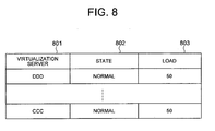
- Fig. 8 shows an example of the state control table 206 in the virtualization server 101 of the control server 102.
- An identifier (ID) of a virtualization server 101 is registered to an entry 801.
- Information indicating a state, specifically, a "normal” or "abnormal” state of the server 101 is registered to an entry 802.
- Information indicating a load imposed on the server 101 is registered to an entry 803.
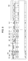
- Fig. 9 shows an example of the virtual volume control table 304 of the virtualization server 101.
- An identifier (ID) of a port to access a virtual volume is registered to an entry 901.
- Information indicating the virtual volume is registered to an entry 902.
- the entry 902 includes an entry 905 to which a logical unit (LU) number of the virtual volume is registered and an entry 906 to which a size of the virtual volume is registered.
- LU logical unit
- An identifier (ID) of a virtualization switch 105 controlling the pertinent virtual volume is registered to an entry 903.
- Information indicating the virtual volume is registered to an entry 904.
- the entry 904 includes an entry 907 to which information indicating the number of real volumes allocated to the virtual volume is registered, an entry 908 to which an identifier (ID) of a port to access a virtual volume is registered, an entry 909 to which a logic unit (LU) number of the virtual volume is registered, an entry 910 to which a size of the real volume is registered, and entries 911 and 912 to which a start address and an end address respectively indicating the start and end positions of an area of the real volume allocated to the pertinent virtual volume are respectively registered.
- LU logic unit
- the respective entries, excepting the entry 907, of the entry 904 are prepared for each virtual volume as many as there are real volumes allocated to the virtual volume.
- the entries 911 and 912 may be omitted.
- the entries 907, 910, 911, and 912 may be omitted.
- Fig. 10 shows an example of the virtual volume control table 404 of the virtualization switch 105.
- An identifier (ID) of a port for the server 101 to access a virtual volume is registered to an entry 1001.
- Information about the virtual volume is registered to an entry 1002.
- An entry 1002 includes an entry 1005 to which a logical unit (LU) number of the virtual volume is registered and an entry 1006 to which a size of the virtual volume is registered.
- LU logical unit
- An identifier (ID) of a virtualization server 104 controlling the pertinent virtual volume is registered to an entry 1003.
- Information indicating information of real volumes constituting the virtual volume is registered to an entry 1004.
- the entry 1004 includes an entry 1007 to which the number of real volumes is registered, an entry 1008 to which an identifier (ID) of a port to for the server to access a real volume is registered, an entry 1009 to which a logic unit (LU) number of the real volume is registered, an entry 1010 to which a size of the real volume is registered, and entries 1011 and 1012 to which a start address and an end address respectively indicating the start and end positions of an area of the real volume allocated to the pertinent virtual volume are respectively registered.
- LU logic unit
- the respective entries, excepting the entry 1007, of the entry 1004 are prepared for each virtual volume as many as there are real volumes allocated to the virtual volume.
- the entries 1002 and 1003 may be omitted.
- the entries 1007, 1010, 1011, and 1012 may be omitted.
- the control server 102 executes processing in response to an instruction from the user as follows. According to a quantity of storage capacity desired by the user, the server 102 selects an appropriate number of real volumes from the real volumes of the storage systems 106 to set the selected real volumes as a virtual volume and then notifies a result of the operation to the user. For this processing, the server 102 executes the volume control program 201.
- Fig. 11 shows in a flowchart a flow of processing of the volume control program 201 executed by the control server 102.
- the server 102 executes processing such as initialization to read the control tables of the control server 102 (1101).
- the server 102 judges to determine whether or not an indication from the user is a virtual volume allocation request (1102). If the indication is a virtual volume allocation request, the server 102 judges to determine, by using the real volume control table 204, whether or not the storage systems 106 have available real volumes (1105).
- control server 102 extracts therefrom a storage area of storage capacity requested by the user and defines the area as one virtual volume or a plurality of virtual volumes.
- the server 102 then updates the contents of the real volume control table 204 and the virtual volume control table 203. Specifically, the contents of the tables are changed such that information indicating the defined virtual volumes is assigned to the available real volumes (1107).
- control server 102 notifies the allocation of the real volumes to the storage systems 106 (1108).
- the server 102 instructs the virtualization node 103, specifically, the virtualization server 104 and the virtualization switch 105 to update the virtual volume control table (1109).
- the server 102 notifies the allocation of the available volumes to the virtual volumes (1110).
- the server 102 then returns to step 1102 and waits for an indication from the user.
- control server 102 If no available volume is detected in step 1105, the control server 102 indicates to the user the impossible allocation of virtual volumes requested by the user (1106) and returns to step 1102 to wait for an indication from the user.
- the control server judges to determine whether or not the user request is a request to terminate the processing (1103). If the request is a processing termination request, the server 102 terminates the processing. Otherwise, the server 102 executes processing associated with the user request (1104) and returns to step 1102 to wait for an indication from the user.
- the user indication may be directly inputted to the control server 102 or may be inputted from another program using a command. Additionally, the notification from the control server 102 to the user may be presented on a display of the control server 102 or may be outputted by another program using a command. The step to notify the real volume allocation to the storage systems 106 may be omitted.
- the control server 102 monitors the state of the virtualization node 103. When a failure or a high load appears in a switch 105 or the like of the virtualization node, the server 102 issues an indication to the virtualization node or the server 101 to change an access route from the server 101 of the user to the storage system 106 to avoid a failure or the like. Through the operation, overall system performance can be kept unchanged.
- the processing is achieved when the server 102 executes the device state control program 202.
- the program 202 is repeatedly executed at a particular interval of time during the system operation or is executed in response to an indication from the user.
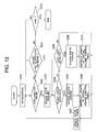
- Fig. 12 shows a flow of processing of the device state control program 202 executed by the control server 102.
- the server 102 executes processing such as initialization to read the control tables (1201).
- the server 102 compares information of a predetermined time with the present time to determine whether or not the present time corresponds to timing to confirm the device state (1202).
- control server 102 accesses the virtualization switch state control table 205 and the virtualization server state control table 206 to issue an enquiry of device state to the virtualization switches 105 and the virtualization servers 104.
- Fig. 16 shows an example of enquiry from the control server to the virtualization node and an example of a reply command to the enquiry.
- the enquiry operation information indicating presence or absence of a device failure and information of a state of the load imposed on the device are communicated.
- the server 102 assumes that a failure occurs in the node 103 (1203).
- the control server 102 When a failure is detected in a device as a result of the enquiry (1204), the control server 102 replaces the access route passing through the device in which the failure is detected with an access route passing through a device in which any failure is not detected. Specifically, the server 102 accesses the virtual volume control table 203 to retrieve virtual volumes supplied to the server 101 via the virtualization server 104 or the virtualization switch 105 in which the failure is detected. Thereafter, the server 102 changes the access routes so that the retrieved virtual volumes are supplied to the server via a normal virtualization switch 105 or a normal virtualization server 104. The server 102 accordingly updates the virtual volume control table (1205).
- the control server 102 indicates the virtualization server 104 and the virtualization switch 105 to update the virtual volume control table.
- the server 102 also transmits information of the device in which the failure has occurred to the server 101 according to necessity (1206).
- the server 102 then updates the virtualization switch state control table 205 and the virtualization server state control table 206. Specifically, the entry corresponding to the failed device is changed from "normal" to "abnormal” (1207).
- control server 102 After the processing is finished, the control server 102 returns to step 1202 and judges to determine whether or not the present time is timing to confirm the device state. If no failure is detected in step 1204, the sever 102 confirms the load state of the virtualization node 103. Specifically, the server 102 confirms the load state obtained as a result of the enquiry to the device (1208).
- the control server 102 changes the access route not to use the device of which the load exceeds the predetermined value, namely, the server 102 takes a detour. Specifically, the server 102 accesses the virtual volume control table 203 to retrieve processing associated with the virtual volumes supplied to the server 101 via the virtualization switch 105 or the virtualization node 104 of which the load exceeds the predetermined value. The server 102 selects particular processing from the retrieved processing and changes access routes of selected processing so that the selected processing is supplied via another virtualization switch 105 or another virtualization node 104. The server 102 updates the virtual volume control table 203.
- a predetermined value e.g. 70%
- the control server 102 indicates the virtualization switch 105 and the virtualization node 104 to update the virtualization volume control table.
- the server 102 sends information of the device of which the load is equal to or more than the predetermined value.
- the virtualization node 103 having received the indication updates the virtualization volume control table. This establishes the new access routes (1210).
- the server 102 updates the virtualization switch state control table 205 and the virtualization server state control table 206 (1207).
- the control server 102 returns to step 1202 to determine whether or not the present time corresponds to timing to confirm the device state. If the load is less than the predetermined value in step 1208, the server 102 updates, according to the information received from the virtualization node 103, the virtualization switch state control table 205 and the virtualization server state control table 206 in step 1207 and then returns to step 1202.
- the control server 102 judges to determine whether or not a device state notification has been received from the virtualization switch 105 or the virtualization server 104. Specifically, the server 102 confirms whether or not a communication control section, not shown, has received a device state notification from each device. Through the confirmation, even if a failure occurs at timing other than the periodic state confirmation point, it is possible to appropriately change associated access routes (1211). If the notification has been received, the server 102 executes processing of step 1204 and subsequent steps.
- the control server 102 returns to step 1202. If the end indication has been received in step 1212, the server 102 terminates the processing. Specifically, when the user indicates the end of processing or when the server 102 recognizes that the predetermined time is past, the server 102 assumes that the end indication is received and terminates the processing.
- the virtualization server 104 updates the control table using the volume control program 301.
- the virtualization server 104 confirms by the volume control program 301 whether or not an indication to update the virtual volume control table has been received from the control server 102. If it is confirmed that the reception of the update indication has been received from the server 102, the virtualization server 104 updates the virtual volume control table 304 according to the update indication.
- the update processing similarly applies to the virtualization switch 105.
- the virtualization switch 105 and the virtualization server 104 having updated the virtual volume control table 304 execute virtualization of the received data according to the contents of the updated virtual volume control table 304.
- the control server 102 has detected an event that a failure occurs in a virtualization server 104 or a load imposed thereon is equal to or more than a predetermined value.
- the control server 102 updates the virtual volume control table 203 to form an access route not using the virtualization server 104. If the load imposed thereon is equal to or more than a predetermined value, the control server 102 updates the virtual volume control table 203 to form an access route such that part of the virtual volume processing being executed by the virtualization server 104 is passed to another virtualization server having a lower load. Thereafter, the control server 102 indicates the virtualization switch 105 and the virtualization server 104 to update the virtual volume control table. Having received the update indication, the switch 105 updates the table according to the indication. The switch 105 processes data to avoid the failed virtualization server 104 according to the updated virtual volume control table. As a result, the data is smoothly processed.
- the virtualization node 103 When a device state enquiry is received from the control server 102, the virtualization node 103 confirms its own state and notifies the state to the server 102. Or, the virtualization node 103 periodically confirms its own state and notifies the state to the server 102.
- the processing is achieved by executing the device state control program 303 and the like.
- the program 303 is executed according to an indication from the user of the control server when the virtualization node 103 is initiated and is repeatedly executed at a particular interval of time.
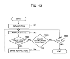
- Fig. 13 shows processing of the device state control program 303 in the virtualization server 104.
- the server 104 conducts initialization (1301).
- the server 104 monitors its own state to update the device state control table 305 according to a change in the state (1302).
- the server 104 confirms whether or not a device state enquiry has been received from the control server 102 (1303). If the enquiry has been received, the server 104 notifies its own state controlled by the table 305 (1304).
- the virtualization server 104 judges to determine occurrence of a state to be notified to the control server 102. For example, the server 104 determines whether or not the state is within a predetermined load (e.g., whether or not a load ratio of 70% is exceeded) or whether or not a failure has occurred in any section of the server 104 (1305).
- a predetermined load e.g., whether or not a load ratio of 70% is exceeded
- the virtualization server 104 If the state is to be notified to the control server 102, the virtualization server 104 notifies its own state to the server 102 (1304). If the state is not to be notified in step 1305, the virtualization server 104 judges to determine whether or not an end indication has been received (1306).
- the server 104 terminates the program to finish the processing. Otherwise, the server 104 returns to step 1302. In this connection, the processing of step 1305 may be omitted.
- the end indication may be, for example, an indication from the user or an indication from a timer in response to a lapse of a predetermined period of time.
- the virtualization switch 105 or the virtualization server 104 processes the data to send a result of the processing to the storage system 106 or the server 101.
- Fig. 14 shows a flow of the virtualization processing 402 executed by the virtualization switch 105.
- the switch 105 conducts initialization (1401). Having received data from a server 101 or a storage system 106 (1402), the switch 105 analyzes the data according to address information in the data.
- the switch 105 determines that the data is sent from a storage system (a real volume allocated to a virtual volume), the data is sent to a server 101 (a virtual volume), or the data source and destination are a storage system 106 or a server 101. According to a result of the analysis, the switch 105 judges to determine whether or not the data requires virtualization (1403). If the data requires virtualization, the switch 105 judges to determine according to the virtual volume control table 404 whether or not the data is to be processed by the virtualization server 104, for example, to be copied by the server 104 (1404).
- the virtualization switch 105 transfers the data to the server 104 (1405). Thereafter, the switch 105 returns to step 1402.
- the switch 105 executes virtualization processing. The processing is specifically executed as below. If the data transmission source is a real volume allocated to a virtual volume, the switch 105 treats the data as data from a virtual volume. If the data transmission source is a virtual volume, the switch 105 treats the data as data from a real volume (1406).
- the virtualization switch 105 transmits the processed data to the destination (1407) and executes processing of step 1402.
- step 1403 If the data does not require the virtualization in step 1403, the switch 105 transmits the data to the destination (1407) and executes processing of step 1402. If it is determined in step 1402 that data has not been received, the switch 105 repeatedly executes processing of step 1402.
- the judgement to determine whether or not the received data is to be processed by the virtualization server 104 or the like may be conducted without using the virtual volume control table 404.
- the judgement may be conducted according to another aspect, for example, according to command information contained in the received data. It is also possible to omit step 1404. In this case, the entire processing of the virtual volume is transferred to the virtualization server 104.
- Fig. 15 shows a flow of the virtualization processing 302 in the virtualization server 104.
- the server 104 conducts initialization (1501). When data is received from a virtualization switch 105 (1502), the server 104 judges to determine whether or not the data is to be processed by the virtualization server 104, for example, whether or not the data is copied by the server 104 (1503). If the data is to be processed by the server 104, the server executes an associated processing for the data.
- processing executed by the virtualization server 104 are as follows.
- the server 104 reads data from a storage area of a storage system 106 and transfers the data to another storage system 106.
- the server 104 issues an instruction that data is read from a storage area of the storage system 106 and is stored the data in another area of the storage system 106.
- the server 104 divides data stored in a storage system 106 into data items and sequentially transfers the data items to a plurality of disk devices of the storage system 106.
- the server generates redundant data according to the divided data items and stores the redundant data in the storage system.
- the virtualization server 104 receives data from a server 101 and stores the data in a plurality of disk devices of the storage system 106 (1504).
- the virtualization server 104 sends the processed data to the virtualization switch 105 (1505). Having transmitted the data, the server 104 returns to step 1502 to continue processing. If it is not determined in step 1503 that the received data is to be processed by the virtualization server 104, the server 104 returns the data to the virtualization switch 105 (1505). The server 104 waits for reception of data in step 1502.
- the virtualization server 104 selects according to the virtual volume control table 304 one of the switches 105 to transfer the data to the selected switch 105.
- control server 102 is separated from the virtualization node 103.
- the virtualization node 103 may include the control server 102.
- either one of a plurality of virtualization servers 104 included in the virtualization node 103 may operate as a control server 102.
- the virtualization node 103 to execute the virtualization processing includes at least one virtualization switch 105 to execute a high-speed processing in which, for example, the switch 105 receives data and converts the data into data of a real volume to transfer the data to an associated storage system 106 and the switch 105 received data from a storage system 106 and converts the data into data from a virtualized volume to send the data to a server 101 and at least one virtualization server 104 which executes complex processing in which, for example, the server 104 copies data between the storage systems 106. Therefore, the virtualization processing in the virtualization node 103 can be executed in a sharing mode. As a result, there can be provided a virtualization system in which the virtualization node 103 does not become a bottleneck of the overall system processing.
- the control server 102 which controls a correspondence between real volumes and virtual volumes and which controls the state of each device of the virtual system detects a virtualization switch 105 or a virtualization server 104 having a high processing load.
- the control server 102 conducts a control operation such that some virtual volumes being processed by the device in which a predetermined load has been detected are moved to a device having a low processing load.
- a virtualization system in which the configuration of the virtualization system is changed according to increase in the processing load in the system to thereby provide stable performance.
- the virtualization node 103 notifies increase in the processing load thereof to the control server 102.
- the control server 102 moves several volumes being processed by devices in the virtualization node 103 to other devices having a low processing load in the virtualization node 103.
- the control server 102 moves processing of a virtual volume being processed by a device in a failed virtualization node 103 to another device in a normal state. Therefore, there can be implemented a virtualization system in which even if a failure occurs in the virtualization system, a device in which an error occurs is easily replaced with a normal device in the virtualization system and hence the failure does not adversely influence any external device.
- the virtualization node 103 notifies a failure thereof to the control server 102.
- the control server 102 moves processing of a virtual volume under processing to a device in a normal state. Therefore, there can be implemented a virtualization system in which even if an error occurs in the virtualization system, a failed device is easily replaced with a normal device in the virtualization system and hence the error does not adversely influence any external device.
Landscapes
- Engineering & Computer Science (AREA)
- Theoretical Computer Science (AREA)
- Human Computer Interaction (AREA)
- Physics & Mathematics (AREA)
- General Engineering & Computer Science (AREA)
- General Physics & Mathematics (AREA)
- Information Retrieval, Db Structures And Fs Structures Therefor (AREA)
Abstract
Description
Claims (14)
- A computer system, comprising:a computer (101);storage systems (106); anda virtualization apparatus (103) for connecting the storage systems to the computer, wherein:said computer includes means (121) for outputting to the virtualization apparatus an access request to the storage systems;the virtualization apparatus includesswitches (105) connected to the storage systems and the computer anda second computer (104);each of said switches includesjudge means (402) for judging whether or not data received from one of the storage systems or one of the computers is data to be processed by one of the second computers andmeans (114) for transmitting, when the data is determined by the judge means as data to be processed by the second computer, the data to the second computer; andeach of said second computer includes means (401-403) for processing the data transferred from one of said switches.
- A computer system according to claim 1, wherein:the processing means of the second computer is means for processing by the second computer the data transferred from the switch and for returning data resulting from the processing to the switch;each of the switches further includes means (122-124) for transmitting the data returned from the processing means to an associated one of the storage systems or the computers.
- A computer system according to claim 1, further comprising a control computer (102) connected to the virtualization apparatus, wherein:said control computer comprises:means (133) for keeping virtualization information, the information being used to virtualize storage areas of the storage systems and to supply the areas;means (131) for updating the virtualization information; andmeans (129) for transmitting to the virtualization apparatus the information updated by the update means.
- A computer system according to claim 3, wherein each of said switches and said second computers include means (134, 135, 401-405, 301-305) for determining, according to the virtualization information sent from the control computer, one of the switches or the second computers to process data sent from the computer.
- A computer system according to claim 3, wherein:each of said switches and said second computers comprisesmeans (303, 403) for monitoring its own load andmeans (126, 130) for transmitting to the control computer information of the load obtained by the monitor means; andsaid control computer comprisesmeans (131, 132, 201, 202) for selecting, according to the information of load received from the switches and the second computers, devices having a predetermined load,means (201, 203) for changing the virtualization information according to information of the devices selected by the selecting means, andmeans (121) for transmitting the virtualization information changed by the changing means to the virtualization apparatus.
- A computer system according to claim 3, wherein:said control computer comprisesmeans (129, 202) for obtaining, from the virtualization apparatus, information indicating a load of the virtualization apparatus,means (205) for changing the virtualization information according to the information obtained by the obtaining means, andmeans (129) for transmitting to the virtualization apparatus the virtualization information changed by the changing means.
- A computer system according to claim 3, wherein:each of said switches and said second computers comprisesmeans (303, 305, 403, 405) for monitoring an operation state thereof andmeans (126, 130) for transmitting to the control computer information of the operation state obtained by the monitor means; andsaid control computer comprisesmeans (131, 132, 201, 202) for selecting, according to the information of the operation states received from the switches and the second computers, devices in which a failure has occurred,means (201, 203) for changing the virtualization information according to information of the devices selected by the selecting means, andmeans (121) for transmitting the virtualization information changed by the changing means to the virtualization apparatus.
- A virtualization apparatus connected to computers (101) and storage systems (106), comprising:switches (105) connected to the storage systems and the computers; andsecond computers (104) connected to the switches, wherein:each of said switches comprisesmeans (402) for confirming data received from one of the computers or the storage system,means for judging, when the confirming means determines that the data is predetermined data, whether or not the data is data to be processed by one of the second computers, andmeans (124) for transmitting, when the judge means determines that the data is to be processed by the second computer, the data to the second computer; andthe second computer comprises means (302) for processing data transferred from the switch.
- A virtualization apparatus according to claim 3, wherein the number of the switches and that of the second computers are two or more.
- A control computer (102) connected to a virtualization apparatus (103) connecting computers (101) and storage systems (106), comprising:means (203) for holding virtualization information of a correspondence between storage areas of the storage systems and virtualized storage areas;means (201) for updating the virtualization information; andmeans (129) for transmitting the information updated by the update means to the virtualization apparatus.
- A control computer according to claim 10, further comprising:means (202) for obtaining, from the virtualization apparatus, information indicating a load on the virtualization apparatus;means (201) for changing the virtualization information according to the information obtained by the obtaining means; andmeans (129) for transmitting the information updated by the update means to the virtualization apparatus.
- A control computer according to claim 10, further comprising:means (202) for obtaining, from the virtualization apparatus, information indicating a failure in the virtualization apparatus;means (201) for changing the virtualization information according to the information obtained by the obtaining means; andmeans (129) for transmitting the information updated by the update means to the virtualization apparatus.
- A method of acquiring information in a computer system comprising a first computer (101), a second computer (102), storage systems (106), and a virtualization apparatus (103) for connecting the storage systems to the computers, comprising the steps of:in the first computer, outputting to the virtualization apparatus an access request to virtualization apparatus;in the virtualization apparatus, judging whether or not data received from the first computer or the storage systems is data to be processed by the second computer;when the data is determined as data to be processed by the second computer, transmitting the data to the second computer; andin the second computer, processing data transferred from the virtualization apparatus.
- A method of acquiring information in a computer system according to claim 13, further comprising the steps of:returning to the virtualization apparatus a processing result of the transmitted data by the second computer; andtransmitting the processing result from said virtualization apparatus to said storage system or said first computer.
Applications Claiming Priority (2)
| Application Number | Priority Date | Filing Date | Title |
|---|---|---|---|
| JP2002103339 | 2002-04-05 | ||
| JP2002103339A JP2003296037A (en) | 2002-04-05 | 2002-04-05 | Computer system |
Publications (2)
| Publication Number | Publication Date |
|---|---|
| EP1351125A2 true EP1351125A2 (en) | 2003-10-08 |
| EP1351125A3 EP1351125A3 (en) | 2008-01-23 |
Family
ID=28035956
Family Applications (1)
| Application Number | Title | Priority Date | Filing Date |
|---|---|---|---|
| EP02019223A Withdrawn EP1351125A3 (en) | 2002-04-05 | 2002-08-27 | Computer system having plural storage systems |
Country Status (3)
| Country | Link |
|---|---|
| US (1) | US7287116B2 (en) |
| EP (1) | EP1351125A3 (en) |
| JP (1) | JP2003296037A (en) |
Families Citing this family (47)
| Publication number | Priority date | Publication date | Assignee | Title |
|---|---|---|---|---|
| US7409583B2 (en) * | 2002-10-07 | 2008-08-05 | Hitachi, Ltd. | Volume and failure management method on a network having a storage device |
| JP4130615B2 (en) * | 2003-07-02 | 2008-08-06 | 株式会社日立製作所 | Fault information management method and management server in a network having a storage device |
| JP4202709B2 (en) * | 2002-10-07 | 2008-12-24 | 株式会社日立製作所 | Volume and failure management method in a network having a storage device |
| JP4139675B2 (en) * | 2002-11-14 | 2008-08-27 | 株式会社日立製作所 | Virtual volume storage area allocation method, apparatus and program thereof |
| US6839740B1 (en) * | 2002-12-27 | 2005-01-04 | Veritas Operating Corporation | System and method for performing virtual device I/O operations |
| US7203801B1 (en) | 2002-12-27 | 2007-04-10 | Veritas Operating Corporation | System and method for performing virtual device I/O operations |
| US8081642B2 (en) | 2003-01-31 | 2011-12-20 | Brocade Communications Systems, Inc. | Method and apparatus for routing between fibre channel fabrics |
| JP2004259079A (en) * | 2003-02-27 | 2004-09-16 | Hitachi Ltd | Data processing system |
| JP4438457B2 (en) * | 2003-05-28 | 2010-03-24 | 株式会社日立製作所 | Storage area allocation method, system, and virtualization apparatus |
| JP4278444B2 (en) * | 2003-06-17 | 2009-06-17 | 株式会社日立製作所 | Virtual port name management device |
| JP4492084B2 (en) * | 2003-10-07 | 2010-06-30 | 株式会社日立製作所 | Storage path control method |
| JP4400913B2 (en) * | 2003-11-26 | 2010-01-20 | 株式会社日立製作所 | Disk array device |
| JP2005165702A (en) * | 2003-12-03 | 2005-06-23 | Hitachi Ltd | Device connection method for cluster storage |
| US20050138184A1 (en) * | 2003-12-19 | 2005-06-23 | Sanrad Ltd. | Efficient method for sharing data between independent clusters of virtualization switches |
| JP4227035B2 (en) | 2004-02-03 | 2009-02-18 | 株式会社日立製作所 | Computer system, management device, storage device, and computer device |
| JP4391265B2 (en) * | 2004-02-26 | 2009-12-24 | 株式会社日立製作所 | Storage subsystem and performance tuning method |
| JP2005251078A (en) | 2004-03-08 | 2005-09-15 | Hitachi Ltd | Information processing apparatus and control method of information processing apparatus |
| US7770059B1 (en) * | 2004-03-26 | 2010-08-03 | Emc Corporation | Failure protection in an environment including virtualization of networked storage resources |
| US20060008782A1 (en) * | 2004-07-08 | 2006-01-12 | Williams Jennette L | Device for teaching phonetic alphabet |
| US7466712B2 (en) * | 2004-07-30 | 2008-12-16 | Brocade Communications Systems, Inc. | System and method for providing proxy and translation domains in a fibre channel router |
| US7936769B2 (en) | 2004-07-30 | 2011-05-03 | Brocade Communications System, Inc. | Multifabric zone device import and export |
| US7096338B2 (en) | 2004-08-30 | 2006-08-22 | Hitachi, Ltd. | Storage system and data relocation control device |
| US7395396B2 (en) | 2004-08-30 | 2008-07-01 | Hitachi, Ltd. | Storage system and data relocation control device |
| JP4555036B2 (en) * | 2004-09-16 | 2010-09-29 | 株式会社日立製作所 | Storage apparatus and device switching control method of storage apparatus |
| US7991783B2 (en) * | 2004-10-05 | 2011-08-02 | International Business Machines Corporation | Apparatus, system, and method for supporting storage functions using an embedded database management system |
| WO2006057059A1 (en) * | 2004-11-29 | 2006-06-01 | Fujitsu Limited | Virtual volume transfer program, and virtual volume transfer method |
| JP2006209237A (en) * | 2005-01-25 | 2006-08-10 | Hitachi Ltd | Storage system, control method therefor, and virtualization apparatus |
| JP4733399B2 (en) * | 2005-01-28 | 2011-07-27 | 株式会社日立製作所 | Computer system, computer, storage device and management terminal |
| US7760717B2 (en) * | 2005-10-25 | 2010-07-20 | Brocade Communications Systems, Inc. | Interface switch for use with fibre channel fabrics in storage area networks |
| JP2007199756A (en) * | 2006-01-23 | 2007-08-09 | Hitachi Ltd | Computer system and data replication method |
| JP4800059B2 (en) * | 2006-02-13 | 2011-10-26 | 株式会社日立製作所 | Virtual storage system and control method thereof |
| JP4908872B2 (en) * | 2006-02-21 | 2012-04-04 | 株式会社日立製作所 | Computer system, management computer, and storage area management method |
| US7428614B2 (en) * | 2006-07-27 | 2008-09-23 | Hitachi, Ltd. | Management system for a virtualized storage environment |
| JP5087249B2 (en) * | 2006-09-06 | 2012-12-05 | 株式会社日立製作所 | Storage system and storage system control method |
| JP2009110218A (en) * | 2007-10-30 | 2009-05-21 | Fujitsu Ltd | Virtualization switch and computer system using the same |
| JP4674242B2 (en) * | 2008-02-05 | 2011-04-20 | 富士通株式会社 | Virtualization switch, computer system, and data copy method |
| JP2009205614A (en) | 2008-02-29 | 2009-09-10 | Fujitsu Ltd | Storage system controlling method, switch device and storage system |
| JP5183363B2 (en) * | 2008-08-26 | 2013-04-17 | 株式会社日立製作所 | Logical volume data migration method, storage system, and management computer |
| US20100251267A1 (en) * | 2009-03-24 | 2010-09-30 | Zwisler Ross E | Caching of SCSI I/O referrals |
| US8527718B2 (en) * | 2009-03-31 | 2013-09-03 | Lsi Corporation | Explicit data segment boundaries with SCSI I/O referrals |
| US8782525B2 (en) * | 2011-07-28 | 2014-07-15 | National Insturments Corporation | Displaying physical signal routing in a diagram of a system |
| JP2014026529A (en) * | 2012-07-27 | 2014-02-06 | Fujitsu Ltd | Storage system and control method thereof |
| US9501379B2 (en) * | 2014-04-11 | 2016-11-22 | Nutanix, Inc. | Mechanism for providing real time replication status information in a networked virtualization environment for storage management |
| US10318194B2 (en) * | 2014-10-02 | 2019-06-11 | Hitachi Vantara Corporation | Method and an apparatus, and related computer-program products, for managing access request in multi-tenancy environments |
| JP2016081194A (en) * | 2014-10-14 | 2016-05-16 | 富士通株式会社 | Storage information extraction program, storage control device, and storage information extraction method |
| US11237747B1 (en) * | 2019-06-06 | 2022-02-01 | Amazon Technologies, Inc. | Arbitrary server metadata persistence for control plane static stability |
| US11971791B2 (en) * | 2022-08-12 | 2024-04-30 | Capital One Services, Llc | Automated regional failover |
Family Cites Families (13)
| Publication number | Priority date | Publication date | Assignee | Title |
|---|---|---|---|---|
| JP2000041068A (en) | 1998-07-23 | 2000-02-08 | Toshiba Corp | ATM repeater |
| JP2000242434A (en) | 1998-12-22 | 2000-09-08 | Hitachi Ltd | Storage system |
| US6542961B1 (en) | 1998-12-22 | 2003-04-01 | Hitachi, Ltd. | Disk storage system including a switch |
| US6601101B1 (en) * | 2000-03-15 | 2003-07-29 | 3Com Corporation | Transparent access to network attached devices |
| JP4175764B2 (en) * | 2000-05-18 | 2008-11-05 | 株式会社日立製作所 | Computer system |
| JP4794068B2 (en) | 2000-06-05 | 2011-10-12 | 富士通株式会社 | Storage area network management system |
| US6625747B1 (en) * | 2000-06-30 | 2003-09-23 | Dell Products L.P. | Computer storage system and failover method |
| US7278142B2 (en) * | 2000-08-24 | 2007-10-02 | Veritas Operating Corporation | Dynamic computing environment using remotely allocable resources |
| JP4457184B2 (en) * | 2001-02-13 | 2010-04-28 | ネットアップ,インコーポレイテッド | Failover processing in the storage system |
| US6944785B2 (en) * | 2001-07-23 | 2005-09-13 | Network Appliance, Inc. | High-availability cluster virtual server system |
| US7958199B2 (en) * | 2001-11-02 | 2011-06-07 | Oracle America, Inc. | Switching systems and methods for storage management in digital networks |
| US7548975B2 (en) * | 2002-01-09 | 2009-06-16 | Cisco Technology, Inc. | Methods and apparatus for implementing virtualization of storage within a storage area network through a virtual enclosure |
| JPWO2003075161A1 (en) | 2002-03-07 | 2005-06-30 | 富士通株式会社 | Conversion management device for storage virtualization system and conversion management method for storage virtualization system |
-
2002
- 2002-04-05 JP JP2002103339A patent/JP2003296037A/en active Pending
- 2002-08-27 EP EP02019223A patent/EP1351125A3/en not_active Withdrawn
- 2002-08-29 US US10/230,174 patent/US7287116B2/en not_active Expired - Fee Related
Also Published As
| Publication number | Publication date |
|---|---|
| US7287116B2 (en) | 2007-10-23 |
| JP2003296037A (en) | 2003-10-17 |
| US20030191904A1 (en) | 2003-10-09 |
| EP1351125A3 (en) | 2008-01-23 |
Similar Documents
| Publication | Publication Date | Title |
|---|---|---|
| US7287116B2 (en) | Storage virtualization system and method having a virtualization switch | |
| US8312233B2 (en) | Storage system that is connected to external storage | |
| JP4297747B2 (en) | Storage device | |
| US7269646B2 (en) | Method for coupling storage devices of cluster storage | |
| JP4147198B2 (en) | Storage system | |
| US10140045B2 (en) | Control device for storage system capable of acting as a constituent element of virtualization storage system | |
| JP4568574B2 (en) | Storage device introduction method, program, and management computer | |
| US7120673B2 (en) | Computer storage system providing virtualized storage | |
| JP4188602B2 (en) | Cluster type disk control apparatus and control method thereof | |
| US7519696B2 (en) | Method and apparatus for dynamically modifying a computer system configuration | |
| US20030236884A1 (en) | Computer system and a method for storage area allocation | |
| EP1760591A1 (en) | Computer system, management computer, method of managing access path | |
| JP2004220450A (en) | Storage device, its introduction method, and its introduction program | |
| JPH11296313A (en) | Storage subsystem | |
| JP2006048627A (en) | Dynamic load balancing for storage systems | |
| US20050050256A1 (en) | Address management device | |
| JP2007148812A (en) | Storage system and load balancing method thereof | |
| JP2006155640A (en) | How to set up access |
Legal Events
| Date | Code | Title | Description |
|---|---|---|---|
| PUAI | Public reference made under article 153(3) epc to a published international application that has entered the european phase |
Free format text: ORIGINAL CODE: 0009012 |
|
| AK | Designated contracting states |
Kind code of ref document: A2 Designated state(s): AT BE BG CH CY CZ DE DK EE ES FI FR GB GR IE IT LI LU MC NL PT SE SK TR |
|
| AX | Request for extension of the european patent |
Extension state: AL LT LV MK RO SI |
|
| 17P | Request for examination filed |
Effective date: 20060331 |
|
| PUAL | Search report despatched |
Free format text: ORIGINAL CODE: 0009013 |
|
| AK | Designated contracting states |
Kind code of ref document: A3 Designated state(s): AT BE BG CH CY CZ DE DK EE ES FI FR GB GR IE IT LI LU MC NL PT SE SK TR |
|
| AX | Request for extension of the european patent |
Extension state: AL LT LV MK RO SI |
|
| AKX | Designation fees paid |
Designated state(s): DE FR GB |
|
| 17Q | First examination report despatched |
Effective date: 20081016 |
|
| STAA | Information on the status of an ep patent application or granted ep patent |
Free format text: STATUS: THE APPLICATION IS DEEMED TO BE WITHDRAWN |
|
| 18D | Application deemed to be withdrawn |
Effective date: 20090227 |