EP1351055A2 - Test strip containers and methods of using the same - Google Patents
Test strip containers and methods of using the same Download PDFInfo
- Publication number
- EP1351055A2 EP1351055A2 EP03252059A EP03252059A EP1351055A2 EP 1351055 A2 EP1351055 A2 EP 1351055A2 EP 03252059 A EP03252059 A EP 03252059A EP 03252059 A EP03252059 A EP 03252059A EP 1351055 A2 EP1351055 A2 EP 1351055A2
- Authority
- EP
- European Patent Office
- Prior art keywords
- test strip
- cover
- container
- subject
- test
- Prior art date
- Legal status (The legal status is an assumption and is not a legal conclusion. Google has not performed a legal analysis and makes no representation as to the accuracy of the status listed.)
- Withdrawn
Links
Images







Classifications
-
- G—PHYSICS
- G01—MEASURING; TESTING
- G01N—INVESTIGATING OR ANALYSING MATERIALS BY DETERMINING THEIR CHEMICAL OR PHYSICAL PROPERTIES
- G01N33/00—Investigating or analysing materials by specific methods not covered by groups G01N1/00 - G01N31/00
- G01N33/48—Biological material, e.g. blood, urine; Haemocytometers
- G01N33/483—Physical analysis of biological material
- G01N33/487—Physical analysis of biological material of liquid biological material
- G01N33/4875—Details of handling test elements, e.g. dispensing or storage, not specific to a particular test method
- G01N33/48778—Containers specially adapted therefor, e.g. for dry storage
-
- G—PHYSICS
- G01—MEASURING; TESTING
- G01N—INVESTIGATING OR ANALYSING MATERIALS BY DETERMINING THEIR CHEMICAL OR PHYSICAL PROPERTIES
- G01N33/00—Investigating or analysing materials by specific methods not covered by groups G01N1/00 - G01N31/00
- G01N33/48—Biological material, e.g. blood, urine; Haemocytometers
- G01N33/483—Physical analysis of biological material
- G01N33/487—Physical analysis of biological material of liquid biological material
- G01N33/4875—Details of handling test elements, e.g. dispensing or storage, not specific to a particular test method
- G01N33/48757—Test elements dispensed from a stack
-
- A—HUMAN NECESSITIES
- A61—MEDICAL OR VETERINARY SCIENCE; HYGIENE
- A61B—DIAGNOSIS; SURGERY; IDENTIFICATION
- A61B10/00—Instruments for taking body samples for diagnostic purposes; Other methods or instruments for diagnosis, e.g. for vaccination diagnosis, sex determination or ovulation-period determination; Throat striking implements
- A61B10/0045—Devices for taking samples of body liquids
-
- Y—GENERAL TAGGING OF NEW TECHNOLOGICAL DEVELOPMENTS; GENERAL TAGGING OF CROSS-SECTIONAL TECHNOLOGIES SPANNING OVER SEVERAL SECTIONS OF THE IPC; TECHNICAL SUBJECTS COVERED BY FORMER USPC CROSS-REFERENCE ART COLLECTIONS [XRACs] AND DIGESTS
- Y10—TECHNICAL SUBJECTS COVERED BY FORMER USPC
- Y10S—TECHNICAL SUBJECTS COVERED BY FORMER USPC CROSS-REFERENCE ART COLLECTIONS [XRACs] AND DIGESTS
- Y10S436/00—Chemistry: analytical and immunological testing
- Y10S436/807—Apparatus included in process claim, e.g. physical support structures
- Y10S436/808—Automated or kit
-
- Y—GENERAL TAGGING OF NEW TECHNOLOGICAL DEVELOPMENTS; GENERAL TAGGING OF CROSS-SECTIONAL TECHNOLOGIES SPANNING OVER SEVERAL SECTIONS OF THE IPC; TECHNICAL SUBJECTS COVERED BY FORMER USPC CROSS-REFERENCE ART COLLECTIONS [XRACs] AND DIGESTS
- Y10—TECHNICAL SUBJECTS COVERED BY FORMER USPC
- Y10T—TECHNICAL SUBJECTS COVERED BY FORMER US CLASSIFICATION
- Y10T436/00—Chemistry: analytical and immunological testing
- Y10T436/25—Chemistry: analytical and immunological testing including sample preparation
Definitions
- the field of this invention is test strip containers.
- Analyte concentration determination in physiological samples is of ever increasing importance to today's society. Such assays find use in a variety of application settings, including clinical laboratory testing, home testing, etc., where the results of such testing play a prominent role in the diagnosis and management of a variety of disease conditions. Analytes of interest include glucose for diabetes management, cholesterol for monitoring cardiovascular conditions, and the like. In response to this growing importance of analyte concentration determination, a variety of analyte concentration determination protocols and devices for both clinical and home testing have been developed.
- test strip Before testing can begin, an individual seeking to determine the presence and/or concentration of an analyte in a physiological sample must first obtain a test strip, apply a sample thereto and obtain the results either manually or automatically with a meter or the like. However, obtaining a test strip to begin the procedure is not without difficulty.
- the ability to easily obtain a test strip, particularly a single test strip from amongst a plurality of test strips is important particularly for those containers and test strips that will be used by persons with diminished hand-eye coordination or finger sensation. For example, persons with diabetes typically have either or both impaired vision and diminished finger sensation or other dexterity problems. Such persons.must use test strips to test their blood glucose levels a number of times a day. However, the typical test strip is only several millimeters in width and length and, thus, difficult to manipulate.
- test strip containers are simple storage reservoirs where the test strips are retained inside and manually removed. However, it is difficult to easily extract a test strip from these containers. These containers are usually shaped and sized to hold a plurality of test strips and to completely encompass the test strips inside so as to protect the test strips from light, humidity, and other environmental contaminants including oils and the like from an individual's hands, where such protection is necessary to insure the precision, accuracy and overall integrity of the test result.
- FIG. 1 An exemplary embodiment of such a simple test strip container is shown in Figure 1.
- an individual has two options for removing a test strip.
- an individual may simply turn the container upside down to pour a test strip out. This, as is apparent, has significant disadvantages as one or all of the test strips stored inside the container may quickly spill out and become contaminated or damaged.
- an individual places a finger inside the container to try to grasp a single test strip amongst a plurality of test strips without damaging or contaminating any of the strips in the process.
- the container must have a suitable shape and a large enough size to accommodate at least one finger therein for easy removal of a test strip. In other words, the container must enable an individual, i.e., an individual who may be visually and/or dextrally impaired, to retrieve a test strip from amongst a plurality of test strips without damaging or contaminating any of such test strips.
- the container while maintaining a size large enough to serve its functions, must be small enough to enable portability of the container so that an individual may easily carry the container at all times to accommodate testing during the course of a day.
- conventional containers are typically cylindrical, i.e., have a circular cross-sectional shape, to accommodate insertion of at least one finger therein, and have a height of about 60 mm and a diameter of about 25 mm and are commercially sold with about 25 test strips retained therein.
- Such size and shape creates a great amount of unused space inside the container, minimizes the portability of the container and adds to the container's costs. In other words, the containers are larger than necessary to simply hold the test strips, thus increasing costs and decreasing portability.
- test strip dispensing there is continued interest in the development of new devices and methods for use in test strip dispensing. Of particular interest would be the development of such devices and methods which are easy and inexpensive to manufacture, have minimal components, are easy to use, particularly for visually and dextrally impaired individuals, are portable and which minimize damage and/or contamination to the test strips contained therein.
- the subject devices are characterized by having a base and a cover, where the cover includes a test strip selecting element.
- the subject devices may also be characterized by having a test strip holding means, which may include one or both of a cover with resiliently deformable walls and a gravity controlled test strip holding mechanism.
- a test strip container with at least one test strip is provided and placed into a position that causes at least one test strip contained in the base to move into the cover so that a single test strip is selected for use.
- the subject methods may also include positioning the device in a particular orientation that causes a selected test strip to be held in a fixed position.
- the subject invention also includes kits which include the subject devices.
- the subject devices are characterized by having a base and a cover, where the cover includes a test strip selecting element.
- the subject devices may also be characterized by having a test strip holding means, which may include one or both of a cover with resiliently deformable walls and a gravity controlled test strip holding mechanism.
- a test strip container with at least one test strip is provided and placed into a position that causes at least one test strip contained in the base to move into the cover so that a single test strip is selected for use.
- the subject methods may also include positioning the device in a particular orientation that causes a selected test strip to be held in a fixed position.
- the subject invention also includes kits which include the subject devices.
- devices are provided for containing and dispensing test strips.
- devices are provided for containing one or more test strips and easily dispensing a test strip therefrom for use and usually the subject devices provide for the easy dispensation of a single test strip from amongst a plurality of test strips, i.e., dispenses each test strip separately or one test strip at a time.
- test strips for example electrochemical and colorimetric or photometric (i.e., optical) type test strips as are known in the art, where such test strips find use in the determination of a wide variety of different analyte concentrations and where representative analytes include, but are not limited to, glucose, cholesterol, lactate, alcohol, and the like.
- test strips used with the subject invention are used to determine the glucose concentration in a physiological sample, e.g., interstitial fluid, blood, blood fractions, constituents thereof, and the like.
- test strips including, but not limited to, the representative colorimetric and electrochemical test strips described herein, may be suitable for use with the present invention.
- suitable test strips is followed by a description of the subject test strip container devices and the subject methods. Finally, a description of kits that include the subject test strip container devices is provided.
- the colorimetric or photometric or optical (herein used interchangeably) reagent test strips employed in these embodiments of the subject invention are generally made up of at least the following components: a matrix 11 for receiving a sample, a reagent composition (not shown as a structural component) that typically includes one or more members of an analyte oxidation signal producing system and a support element 12.
- the colorimetric test strips are usually configured and adapted to be received in an automated meter, as described below, for automatically determining the concentration of an analyte.
- An exemplary embodiment of a representative colorimetric test strip is shown in Figure 2A.
- Figure 2A shows colorimetric test strip 80 in which a matrix 11 is positioned at one end of support element 12 with an adhesive 13.
- a hole 14 is present in the support element 12 in the area of matrix 11 in which a sample can be applied to one side of the matrix 11 and a reaction can be detected on an opposite side of matrix 11.
- Matrix 11 that is employed in the subject test strips is an inert matrix which provides a support for the various members of the signal producing system, described below, as well as the light absorbing or chromogenic product produced by the signal producing system, i.e ., the indicator.
- Matrix 11 is configured to provide a location for the physiological sample, e.g ., blood, application and a location for the detection of the light-absorbing product produced by the indicator of the signal producing system.
- matrix 11 is one that is permissive of aqueous fluid flow through it and provides sufficient void space for the chemical reactions of the signal producing system to take place.
- matrices have been developed for use in various analyte detection assays, which matrices may differ in terms of materials, dimensions and the like, where representative matrices include, but are not limited to, those described in U.S. Patent Nos.: 4,734,360; 4,900,666; 4,935,346; 5,059,394; 5,304,468; 5,306,623; 5,418,142; 5,426,032; 5,515,170; 5,526,120; 5,563,042; 5,620,863; 5,753,429; 5,573,452; 5,780,304; 5,789,255; 5,843,691; 5,846,486; 5,968,836 and 5,972,294; the disclosures of which are herein incorporated by reference.
- matrix 11 is not critical to the subject test strips and therefore is chosen with respect to other factors, including the nature of the instrument which is used to read the test strip, convenience and the like.
- the dimensions and porosity of the test strip may vary greatly, where matrix 11 may or may not have pores and/or a porosity gradient, e.g . with larger pores near or at the sample application region and smaller pores at the detection region.
- Materials from which matrix 11 may be fabricated vary, and include polymers, e.g . polysulfone, polyamides, cellulose or absorbent paper, and the like, where the material may or may not be functionalized to provide for covalent or non-covalent attachment of the various members of the signal producing system.
- the subject test strips further include one or more members of a signal producing system which produces a detectable product in response to the presence of analyte, which detectable product can be used to derive the amount of analyte present in the assayed sample.
- the one or more members of the signal producing system are associated, e.g ., covalently or non-covalently attached to, at least a portion of ( i.e ., the detection region) the matrix, and in many embodiments to substantially all of the matrix.
- the signal producing system is an analyte oxidation signal producing system.
- analyte oxidation signal producing system is meant that in generating the detectable signal from which the analyte concentration in the sample is derived, the analyte is oxidized by one or more suitable enzymes to produce an oxidized form of the analyte and a corresponding or proportional amount of hydrogen peroxide.
- the hydrogen peroxide is then employed, in turn, to generate the detectable product from one or more indicator compounds, where the amount of detectable product generated by the signal measuring system, i.e . the signal, is then related to the amount of analyte in the initial sample.
- the analyte oxidation signal producing systems present in the subject test strips are also correctly characterized as hydrogen peroxide based signal producing systems.
- the hydrogen peroxide based signal producing systems include an enzyme that oxidizes the analyte and produces a corresponding amount of hydrogen peroxide, whereby corresponding amount is meant that the amount of hydrogen peroxide that is produced is proportional to the amount of analyte present in the sample.
- This first enzyme necessarily depends on the nature of the analyte being assayed but is generally an oxidase.
- the first enzyme may be: glucose oxidase (where the analyte is glucose); cholesterol oxidase (where the analyte is cholesterol); alcohol oxidase (where the analyte is alcohol); lactate oxidase (where the analyte is lactate) and the like.
- Other oxidizing enzymes for use with these and other analytes of interest are known to those of skill in the art and may also be employed.
- the first enzyme is glucose oxidase.
- the glucose oxidase may be obtained from any convenient source, e.g . a naturally occurring source such as Aspergillus niger or Penicillum, or recombinantly produced.
- a second enzyme of the signal producing system may be an enzyme that catalyzes the conversion of one or more indicator compounds into a detectable product in the presence of hydrogen peroxide, where the amount of detectable product that is produced by this reaction is proportional to the amount of hydrogen peroxide that is present.
- This second enzyme is generally a peroxidase, where suitable peroxidases include: horseradish peroxidase (HRP), soy peroxidase, recombinantly produced peroxidase and synthetic analogs having peroxidative activity and the like. See e.g ., Y. Ci, F. Wang; Analytica Chimica Acta, 233 (1990), 299-302.
- the indicator compound or compounds, e.g ., substrates are ones that are either formed or decomposed by the hydrogen peroxide in the presence of the peroxidase to produce an indicator dye that absorbs light in a predetermined wavelength range.
- the indicator dye absorbs strongly at a wavelength different from that at which the sample or the testing reagent absorbs strongly.
- the oxidized form of the indicator may be a colored, faintly-colored, or colorless final product that evidences a change in color of the testing side of the membrane. That is to say, the testing reagent can indicate the presence of glucose in a sample by a colored area being bleached or, alternatively, by a colorless area developing color.
- Indicator compounds that are useful in the present invention include both one-and two-component chromogenic substrates.
- One-component systems include aromatic amines, aromatic alcohols, azines, and benzidines, such as tetramethyl benzidine-HCl.
- Suitable two-component systems include those in which one component is MBTH, an MBTH derivative (see for example those disclosed in U.S. Patent Application Ser. No. 08/302,575, incorporated herein by reference), or 4-aminoantipyrine and the other component is an aromatic amine, aromatic alcohol, conjugated amine, conjugated alcohol or aromatic or aliphatic aldehyde.
- Exemplary two-component systems are 3-methyl-2-benzothiazolinone hydrazone hydrochloride (MBTH) combined with 3-dimethylaminobenzoic acid (DMAB); MBTH combined with 3,5-dichloro-2-hydroxybenzene-sulfonic acid (DCHBS); and 3-methyl-2-benzothiazolinonehydrazone N-sulfonyl benzenesulfonate monosodium (MBTHSB) combined with 8-anilino-1 naphthalene sulfonic acid ammonium (ANS).
- the dye couple MBTHSB-ANS is preferred.
- signal producing systems that produce a fluorescent detectable product (or detectable non- fluorescent substance, e.g . in a fluorescent background) may be employed, such as those described in: Kiyoshi Zaitsu, Yosuke Ohkura: New fluorogenic substrates for Horseradish Peroxidase: rapid and sensitive assay for hydrogen peroxide and the Peroxidase. Analytical Biochemistry (1980) 109, 109-113.
- Matrix 11 is usually attached to a support element 12.
- Support element 12 may be of a material that is sufficiently rigid to be inserted into an automated device such as a meter without undue bending or kinking.
- Matrix 11 may be attached to support element 12 by any convenient mechanisms, e.g., clamps, adhesive, etc., herein shown attached using an adhesive 13.
- support member 12 is made of material such as polyolefins, e.g ., polyethylene or polypropylene, polystyrene or polyesters. Consequently, the length of the support element 12 typically dictates or corresponds to the length of the test strip.
- the total length of the test strip 80 generally ranges from about 5 mm to about 80 mm, usually from about 15 mm to about 65 mm and more usually from about 40 mm to about 55 mm
- the width of the test strip 80 typically ranges from about 2 mm to about 35 mm, usually from about 5 mm to about 20 mm and more usually from about 7 mm to about 15 mm
- the thickness of the test strip 80 typically ranges from about 0.2 mm to about 7.5 mm, usually from about 0.4 mm to about 2.0 mm and more usually from about 0.6 mm to about 1.5 mm.
- support element 12 is usually configured to enable test strip 80 to be used with or inserted into a meter.
- support element 12, and thus test strip is typically in the form of a substantially rectangular or square-like strip, where the dimensions of support element 12 vary according to a variety of factors, as will be apparent to those of skill in the art.
- sample is allowed to react with the members of the signal producing system to produce a detectable product that is present in an amount proportional to the initial amount present in the sample.
- the amount of sample that is introduced to matrix 11 of the test strip may vary, but generally ranges from about 0.1 to 25 ⁇ l, usually from about 5 to 10 ⁇ l.
- the sample may be introduced to matrix 11 using any convenient protocol, where the sample may be injected, allowed to wick, or be otherwise introduced.
- the amount of detectable product, i.e ., signal produced by the signal producing system is then determined and related to the amount of analyte in the initial sample.
- automated meters that perform the above mentioned detection and relation steps are employed.
- colorimetric reagent test strips examples include, but are not limited to, those described in U.S. Patent Nos. 5,049,487; 5,563,042; 5,753,452; 5,789,255, the disclosures of which are herein incorporated by reference.
- the electrochemical test strips that find use with the subject invention are made up of two opposing metal electrodes separated by a thin spacer layer.
- a redox reagent system is located in the reaction area or zone.
- the electrochemical test strips may be configured and adapted to be received in an automated meter, as described below, for automatically determining the concentration of an analyte.
- Figure 2B shows an exploded view of an exemplary embodiment of a representative electrochemical test strip.
- Test strip 62 includes a reference electrode 64 and a working electrode 66 separated by a spacer layer 60 which is cut away to define a reaction area or zone 68 in communication with side ports 70 defined by a break in the spacer layer's coverage adjacent reagent system or composition 72.
- the working electrode 66 and reference electrode 64 are further characterized in that at least the surfaces of the electrodes that face the reaction area 68 of the electrochemical cell in the strip is a metal, where metals of interest include palladium, gold, platinum, silver, iridium, carbon (conductive carbon ink), doped tin oxide, stainless steel and the like.
- metals of interest include palladium, gold, platinum, silver, iridium, carbon (conductive carbon ink), doped tin oxide, stainless steel and the like.
- the metal is gold or palladium.
- each of the electrodes is generally made up of an inert support material on the surface of which is present a thin layer of the metal component of the electrode.
- Any convenient inert support material may be employed in the subject electrodes, where typically the material is a rigid material that is capable of providing structural support to the electrode and, in turn, the electrochemical test strip as a whole.
- Suitable materials that may be employed as the inert support material include plastics, e.g. , polyethylene terephthalate (PET), polyethylene terephthalate glycol modified (PETG), polyimide, polycarbonate, polystyrene, silicon, ceramic, glass, and the like.
- the support itself may be made of metal, especially one of those noted above.
- the electrode is a composite of a support coated with a metallic and/or conductive coating (such as palladium, gold, platinum, silver, iridium, carbon conductive carbon ink doped tin oxide or stainless steel).
- metal-coated support When a metal-coated support is to be employed, its thickness (metal and support) will typically range from about 0.002 to about 0.014 in (about 51 ⁇ m to about 356 ⁇ m), usually from about 0.004 to about 0.007 in (about 102 ⁇ m to about 178 ⁇ m), while the thickness of the metal layer will typically range from about 10 to 300 nm and usually from about 20 to 40nm.
- the working and reference electrodes 66 and 64 are generally configured in the form of elongate strips.
- the length of the electrodes ranges from about 0.64 cm to about 7.6 cm, usually about 2.0 cm to about 3.8 cm.
- the width of the electrodes typically ranges from about 0.025 cm to about 0.76 cm, usually from about 0.25 cm to about 0.67 cm. In certain embodiments, the length of one of the electrodes is shorter than the other. Oftentimes, the electrode and spacer width is matched where the elements overlap.
- electrode 64 is about 3.5 cm long
- electrode 66 is about 3.8 cm long
- each are about 6.4 mm wide at their maximum and about 2.6 mm wide at their minimum
- reaction zone 68 and ports 70 are about 1.65 mm wide and the reaction zone 68 has an area of about 0.041 cm 2 .
- Spacer 60 incorporated in the strip may be set back, e.g., about 7.6 mm from the end of electrode 66.
- the reaction area or zone 68 in which activity occurs preferably has a volume of at least about 0.1 ⁇ l, usually at least about 0.3 ⁇ l and more usually at least about 0.6 ⁇ l, where the volume may be as large as 10 ⁇ l or larger.
- the size of zone 68 is largely determined by the characteristics of spacer layer 60. While spacer layer 60 is shown to define a rectangular reaction area in which the aforementioned activity occurs, other configurations are possible, (e.g., square, triangular, circular, irregular-shaped reaction areas, etc.).
- the thickness of spacer layer 60 generally ranges from about 25 ⁇ m to about 500 ⁇ m, usually from about 76 ⁇ m to about 127 ⁇ m, thus the total thickness of the test strip (electrodes and spacer layer) typically ranges from about 127 ⁇ m to about 1270 ⁇ m, usually from about 254 ⁇ m to about 762 ⁇ m and more usually from about 380 ⁇ m to about 510 ⁇ m.
- the manner in which spacer layer 60 is cut also determines the characteristics of ports 70.
- the cross-sectional area of inlet and outlet ports 70 may vary as long as it is sufficiently large to provide an effective entrance or exit of fluid from reaction area 68.
- a reagent system or composition 72 is present in the reaction area, where reagent system 72 interacts with components in the fluid sample during the assay.
- Reagent systems of interest typically include a redox couple.
- the redox couple of the reagent composition when present, is made up of one or more redox couple agents.
- redox couple agents include: ferricyanide, phenazine ethosulphate, phenazine methosulfate, pheylenediamine, 1-methoxy-phenazine methosulfate, 2,6-dimethyl-1,4-benzoquinone, 2,5-dichloro-1,4-benzoquinone, ferrocene derivatives, osmium bipyridyl complexes, ruthenium complexes, and the like.
- Other reagents that may be present in the reaction area include buffering agents, e.g. , citraconate, citrate, malic, maleic, phosphate, "Good" buffers and the like.
- agents that may be present include: divalent cations such as calcium chloride, and magnesium chloride; surfactants such as Triton, Macol, Tetronic, Silwet, Zonyl, and Pluronic; stabilizing agents such as albumin, sucrose, trehalose, mannitol, and lactose.
- divalent cations such as calcium chloride, and magnesium chloride
- surfactants such as Triton, Macol, Tetronic, Silwet, Zonyl, and Pluronic
- stabilizing agents such as albumin, sucrose, trehalose, mannitol, and lactose.
- examples of such a reagent test strips suitable for use with the subject invention include those described in U.S. Patent No. 6,193,873, EP-A-1 252 514, EP-A-1 254 365, WO-A-02/48707 and WO-A-02/50609.
- an aqueous liquid sample e.g. , blood
- the amount of physiological sample that is introduced into the reaction area of the test strip may vary, but generally ranges from about 0.1 to 10 ⁇ l, usually from about 0.3 to 0.6 ⁇ l.
- the sample may be introduced into the reaction area using any convenient protocol, where the sample may be injected into the reaction area, allowed to wick into the reaction area, or be otherwise introduced through the ports.
- the component to be analyzed is allowed to react with the redox reagent coating to form an oxidizable (or reducible) substance in an amount corresponding to the concentration of the component to be analysed ( i.e ., analyte).
- the quantity of the oxidizable (or reducible) substance present is then estimated by an electrochemical measurement.
- the measurement that is made may vary depending on the particular nature of the assay and the device with which the electrochemical test strip is employed ( e.g ., depending on whether the assay is coulometric, amperometric or potentiometric).
- Measurement with strip 62 is preferably accomplished by way of an automated instrument or meter. Usually, measurement is taken over a given period of time following sample introduction into the reaction area. Methods for making electrochemical measurements are further described in U.S. Patent Nos.: 4,224,125; 4,545,382; and 5,266,179; as well as WO 97/18465 and WO 99/49307 publications, the disclosures of which are herein incorporated by reference.
- the amount of the analyte present in the sample introduced into the reaction zone is then typically determined by relating the electrochemical signal to the amount of analyte in the sample.
- the measures electrochemical signal is usually compared to the signal generated from a series of previously obtained control or standard values, and determined from this comparison.
- the electrochemical signal measurement steps and analyte concentration derivation steps are performed automatically by a device designed to work with the test strip to produce a value of analyte concentration in a sample applied to the test strip, as noted above.
- a representative reading device for automatically practicing these steps, such that user need only apply sample to the reaction zone and then read the final analyte concentration result from the device, is further described in EP-A-1 067 384.
- the subject invention includes devices that contain and easily dispense a test strip, such as the type of test strip described above, where the subject test strip container devices have minimal components and prevent or minimize test strip contact with adverse contaminants such as dirt and oils or other contaminants from human hands, etc.
- the subject devices dispense a single test strip from a plurality or aggregate of contained test strips.
- the subject devices are configured to retain from about 1 to about 50 test strips at one time, usually about 5 to about 40 test strips at one time and more usually from about 10 to about 25 test strips at one time, however the subject devices may be configured to retain a greater or fewer number of test strips at one time.
- the subject devices also allow for easy re-loading of additional test strips, as will be apparent from the descriptions below.
- electrochemical test strips of the type described above will be used herein for exemplary purposes and is in no way intended to limit the scope of the invention.
- Figure 3A shows the exterior of an exemplary embodiment of a subject test strip container 2 having a base 4 and a cover 6 and having a cylindrical shape.
- Cover 6 and base 4 are removably connected or associated to each other using any convenient means, for example they may be associated using corresponding threads, a hinge, friction, a snap fit, etc., or any combination thereof and may include a gasket therebetween in certain embodiments.
- Base 4 and cover 6 will be associated such that cover 6 may be readily and easily separated from base 4.
- the shape of container 2 will necessarily vary depending on a variety of factors, where such factors include, but are not limited to, the type, size and number of test strips retained therein, and the like.
- Figure 3A shows test strip container 2 having a cylindrical shape, but other shapes are possible as well.
- the shape of container 2 may have any of a variety of shapes ranging from simple to complex, where the shape of base 4 may differ from the shape of cover 6.
- base 4 of the container 2 may be of a rectangular, square, cylindrical, circular, elliptical or oval shape, etc., or substantially so.
- the shape of base 4 may be more complex such as a substantially irregular shape or the like.
- the shape of cover 6 may also assume a variety of shapes such as those described above with reference to base 4.
- cover 6 will assume a substantially irregular shape as shown in Figure 3B.
- Figure 3B shows cover 6 of Figure 3A having a somewhat irregular shape due to tapered portions or indents 5 positioned on opposing sides of cover 6, where indents 5 enable an individual to easily grasp and hold cover 6 and in certain embodiments at least those walls that include indents 5 are resiliently deformable walls as will be described in greater detail below.
- test strip container 2 may also vary depending on a variety of factors such as the type, size and number of test strips retained therein, and the like.
- Container 2 is configured such that the plurality of test strips is held primarily in base portion 4 of container 2 when container 2 is substantially upright.
- Container 2 will typically be sized to be easily held and transported by an individual.
- the length of container 2 typically ranges from about 12 mm to about 100 mm, usually from about 25 mm to about 75 mm and more usually from about 35 to about 51 mm and the width/diameter of the container 2 ranges from about 10 mm to about 40 mm, usually from about 15 mm to about 35 mm and more usually from about 20 to about 25 mm.
- the container 2 may be manufactured from a variety of materials, where the base 4 and cover 6 of the container 2 may be manufactured from the same or different materials, but where such materials will not substantially interfere with the testing reagents of the test strips retained therein.
- a portion of the container 2 may be made of a resiliently deformable or flexible material.
- at least cover 6 or at least one or more walls thereof may be made of a material that is easily resiliently deformable or flexible such that the one or more walls may be deformed upon slight pressure applied by an individual thereto and where the walls will assume their original configuration upon release of the pressure thereto, as will be described in greater detail below.
- Representative materials that may be used in subject container 2 include, but are not limited to, polymeric materials such as polytetrafluoroethylene, polypropylene, polyethylene, polystyrene, polycarbonate and blends thereof, metals such as stainless steel, aluminum and alloys thereof, TeflonTM, siliceous material, e.g., glass materials, and the like.
- base 4 and cover 6 are associated or alignable in a closed configuration such that the device is substantially or completely air and moisture tight when in such a closed configuration.
- the interior of container 2 is substantially air and moisture tight when base 4 and cover 6 are brought together to form a closed container 2.
- the subject container 2 may further include moisture absorbent reagents or components such as desiccant material, silica gel and the like, where such material is capable of absorbing moisture from the environment surrounding the stored test strips.
- moisture absorbent reagents or components such as desiccant material, silica gel and the like, where such material is capable of absorbing moisture from the environment surrounding the stored test strips.
- Such absorbent reagents or components may be retained in one or more compartments positioned inside cover 6 and/or base 4.
- test strip containers are capable of dispensing a single test strip at one time for use.
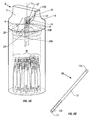
- a feature of the subject devices is the presence of a test strip selecting element 20 (see Figure 4) that is capable of selecting a single test strip 30a contained in the subject container 2 so that it may be used. That is, where a subject container 2 contains a plurality of test strips, test strip selecting element 20 is capable of easily selecting a single test strip 30a, i.e., it separates a single test strip 30a from other test strips 30, and positions it for use.
- Test strip selecting element 20 operates by simple manipulation or handling of a subject container 2, i.e., it does not require an individual to actuate the device or any component thereof, and thus is passively activated and particularly well suited for an individual who has dexterity problems such as diminished fingertip sensation and/or is visually impaired.
- test strip selecting element 20 selects and positions a test strip 30a for use when container 2 is positioned in a particular orientation relative to the ground. More specifically, the test strip selecting element 20 selects and positions a test strip 30a by a simple rotation or turning of container 2 to a substantially upside down position.
- the subject container 2 also includes a test strip holding means for holding a test strip, such as a test strip that has been selected by a test strip selecting element, in a fixed position relative to cover 6.
- the test strip holding means also does not require an individual to actuate the device or any component thereof, i.e., is passively activated.
- Test strip selecting element 20 will now be described in greater detail, followed by a description of the subject test strip holding means.
- test strip container 2 includes test strip selecting element 20 positioned in cover 6.
- test strip selecting element 20 selects a test strip 30a to be held by a test strip holding means, as will be described in more detail below.
- test strip selecting element 20 selects or separates a single test strip 30a from the plurality or aggregate of test strips 30.
- test strip selecting element 20 includes an area or cavity 25 that has a continuously reduced diameter or continuously reduced cross-sectional area.
- shape of cavity 25 may be characterized as substantially frustum-shaped.
- Substantially frustum-shaped cavity 25 includes first end 21 and second end 23.
- Substantially frustum-shaped cavity 25 opens on second end 23 that is in direct communication with base 4 and through which at least one test strip, and more usually a plurality of test strips, previously contained in the base 4 of the container 2 moves, so that a single test strip may be selected at first end 21 of test strip selecting element 20.
- test strip selecting element 20 funnels at least one test strip through a substantially frustum-shaped cavity 25 thereof so as to ultimately select a single test strip 30a in an opening or slot 22 of test strip selecting element 20.
- the remaining test strips 30 are prevented from passing all the way through test strip selecting element 20 to slot 22 and, as such, remain in cavity 25 of test strip selecting element 20 and/or base 4 until selected for later use by an individual.
- the cross-sectional shape of continuously reduced diameter cavity 25 may vary depending on a variety of factors such as the size and shape of the test strip to be dispensed, etc., with the only limitation that cavity 25 is capable of funneling at least one test strip therethrough.
- the cross sectional shape of substantially frustum-shaped cavity 25 may be rectangular, square, circular, elliptical, etc. Accordingly, the cross-sectional shapes of the exemplary embodiments of substantially frustum-shaped cavity 25 shown herein are for exemplary purposes only and are not intended to limit the scope of the invention.
- test strip selecting element 20 is configured within cover 6 such that when container 2 is appropriately positioned, test strips 30 retained in base 4 move into test strip selecting element 20.
- appropriate position is meant that the device is positioned substantially upside down. That is, if the device is originally oriented in a substantially upright orientation, then the device is turned or rotated so that the device is substantially upside down.
- container 2 is at an angle ⁇ (see Figure 9A) that ranges from about -30° to about + 30° relative to the longitudinal axis L 2 of the container 2 when the longitudinal axis L 2 of the container 2 is positioned perpendicular to the ground G and base 4 is closer to ground G than cover 6 is positioned with respect to the ground G.
- container 2 is at an angle ⁇ (see figure 9B) that ranges from about -20° to about + 20° relative to the longitudinal axis L 2 of the container 2 when the longitudinal axis L 2 of the container 2 is positioned perpendicular to the ground G and the cover 6 is closer to the ground G than the base 4 is positioned with respect to the ground G.
- test strip selecting element 20 can be characterized as having a first end 21 that includes slot 22, a second end 23 positioned at opening 7 of cover 6 which is in direct communication with base 4, and a substantially frustum-shaped cavity 25 positioned between first end 21 and second end 23.
- Test strip selecting element 20 may be a unitary piece of construction with respect to cover 6, i.e., may be molded in cover 6, or may a separate component that is attached to the interior of cover 6 by any convenient means, including welding, adhesives, friction, snap fit, etc., and any combination thereof.
- test strip selecting element 20 will be a unitary piece of construction with respect to cover 6.
- cavity 25 of test strip selecting element 20 is substantially frustum shaped or funnel-like, i.e., has a substantially funnel shape such that it has walls that taper towards slot 22 of first end 21, e.g., a cone-like shape, although it need not be cylindrical in shape as long as the walls taper inwardly towards slot 22.
- the diameter or cross sectional area of test strip selecting element 20 gradually decreases from second side 23 to slot 22 of first side 21. That is, the diameter of test strip selecting element 20 decreases to an ultimate diameter or area that only accommodates or is only permissive of a single test strip.
- Figure 6 shows an enlarged view of test strip selecting element 20 of Figure 5 in a substantially upside down position having a single test strip 30a selected in slot 22 from amongst a plurality of test strips 30.
- the substantially frustum or funnel-like shape of cavity 25 enables test strip selecting element 20 to select a single test strip 30a in slot 22 as the number of the test strips that are able to be accommodated in cavity 25 decreases from the second side 23 to the first side 21 when the device is appropriately positioned, such that ultimately one single test strip 30a is separated from the aggregate 30 and selected in slot 22, as shown in Figures 4, 5 and 6.
- the selected test strip 30a is positioned in slot 22 such that a portion of the test strip 30a resides in slot 22 and a portion protrudes or extends within or through cavity 25.
- Slot 22 is sized and shaped for selecting or being permissive of only a single test strip therein at one time.
- the size and/or shape of slot 22 need not necessarily correspond to that of a test strip, i.e., the size and/or shape of slot 22 may differ from the size and/or shape (width) of a test strip, as long as slot 22 enables a single test strip to be selected thereby, e.g., a test strip may be rectangular in shape and slot 22 may be of a shape other than rectangular.
- the length of slot 22 will typically range from about 3 mm to about 50 mm, usually from about 5 mm to about 25 mm and more usually from about 6 mm to about 10 mm
- the width of slot 22 in this embodiment configured to accommodate the narrow portion of the test strip
- the depth or thickness of slot 22 will typically range from about 128 ⁇ m to about 2400 ⁇ m.
- the interior of the test strip selecting element 20 further includes a test strip directing element 27, i.e., the interior of the funnel-like cavity 25 includes a structure for directing at least one test strip therethrough.
- a test strip directing element 27 may be positioned on the interior of the test strip selecting element 20 to direct the test strip(s) towards the slot 22 and assist in separating a single test strip from others.
- the directing element 27 may be positioned in any suitable manner.
- a series of ridges or steps may encircle the entire interior of the test strip selecting element 20 or may be positioned on a portion of the interior such as on two opposing sides of the test strip selecting element 20. Opposing steps may be graduated or offset in such a manner that the top of one step corresponds with the rise of an opposing step.
- Figure 7 shows a cross sectional view through an exemplary test strip selecting element, such as a cross section taken along line x-x of test strip selecting element 20 of Figure 5 having test strip 30a removed from test strip selecting element 25 to provide a better view of directing element 27.
- Figure 7 shows test strip selecting element 20 having a series of steps or ridges 27 positioned at least on two opposing sides of the interior of the test strip selecting element 20.
- the subject invention also includes at least one test strip holding means for holding a test strip in a fixed position relative to cover 6, for example once the test strip has been selected by a test strip selecting element.
- the test strip holding means includes a cover that has resiliently deformable walls (see Figure 11).
- the test strip holding means includes a test strip holding mechanism that is gravity controlled (see Figure 8A).
- the test strip holding means will be further described herein with reference to holding a test strip 30a selected by a test strip selecting element 20, as described above. However, it is understood that this description is by way of example only and is in no way intended to limit the scope of the invention. That is, the test strip holding means may be used to hold any test strip placed in a suitable position using any convenient means.
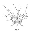
- FIG. 11 shows an exemplary embodiment of cover 6 having resiliently deformable walls 17 and 18.
- deformable is meant that one or more walls of a cover, typically at least two opposing walls, are capable of being urged inwardly or squeezed together upon application of a suitable force thereto.
- resiliently deformable is meant that the deformation is not permanent and the walls are capable of resuming their original configuration upon release of force thereto.
- Any and all embodiments of the subject covers described herein may include one or more walls that are capable of resiliently deforming, such as walls 17 and 18 shown in Figure 11 that include indents 5.
- At least two opposing walls of a resiliently deformable cover 6 are made of a material that is resiliently deformable upon application of a slight force by an individual thereto, such as those materials described above.
- the at least two opposing walls 17 and 18 are capable of deforming to such an extent that a test strip may be held in a fixed position therebetween. That is, at least two opposing walls are capable of being squeezed together to hold or pinch a test strip between them.
- test strip holding mechanism 10 includes a channel 12 positioned adjacent slot 22 of test strip selecting element 20, wherein at least one slideable contact element 14 is disposed within channel 12.
- Figure 8B shows an enlarged view of the test strip holding mechanism 10 of Figure 8A.
- Channel 12 includes an open proximal end 12a and a distal end 12b, where distal end 12b may be opened or closed.
- contact element 14 when a contact element 14 is positioned adjacent open proximal end 12a of channel 12, contact element 14 slightly protrudes therefrom, i.e., a portion of contact element 14 extends from channel 12.
- the slightly protruding contact element 14 may directly contact a test strip, such as test strip 30a that has been selected by slot 22 of test strip selecting element 20.
- the number of contact elements 14 within channel 12 may vary, but will typically range from about 1 to about 20, usually from about 1 to about 10 and more usually from about 1 to about 4, however a greater or fewer number of contact elements 14 may be present.
- Test strip holding mechanism 10 is gravity controlled in that the contacting element(s) 14 are caused to engage or contact a test strip 30a when gravitational forces urge them against test strip 30a that is positioned in slot 22, which test strip 30a was once contained in base 4, i.e., when the device is handled such that the contact element(s) 14 slideably move adjacent proximal end 12a, as shown in Figures 8A and 8B and as will be described in more detail below.
- test strip holding mechanism 10 is gravity-controlled wherein gravitational forces cause the one or more contact elements 14 to slide or move within channel 12 when container 2 is moved to a substantially upright position, as described above, where such contact element(s) 14 are thus caused to contact a selected test strip 30a and hold it in a fixed position relative to cover 6.
- channel 12 of the gravity-controlled test strip holding mechanism is positioned at an angle within cover 6 such that contact element(s) 14 therein are capable of slideably moving within channel 12 when cover 6 is positioned appropriately.
- the test strip holding mechanism 10 defines an obtuse angle ⁇ relative to the longitudinal axis L 1 of the cover 6, as shown in Figure 8A. That is, the angle ⁇ is such that when the container 2 is substantially upright, as shown in Figure 8A, gravity forces act upon the contact element(s) 14 therein to slideably move the contact element(s) 14 in a direction towards open proximal end 12a of channel 12.
- angle ⁇ will vary according to a variety of factors, including, but not limited to, the size, shape, weight and material(s) of construction of the contact element(s) 14, etc.
- angle ⁇ of the channel 12 ranges from about 120° to about 170° and more typically ranges from about 135° to about 150° relative to the longitudinal axis L 1 of cover 6.
- the shape of the one or more contact elements 14 is not critical to the subject invention, where the shape thereof may include, but is not limited to, spherical such as spherical ball bearings, rod-like, tubular, round, disc, square, spherical, oblong, plate, cylindrical, etc., as long as the contact element(s) 14 are capable of sliding or moving within channel 12.
- spherical such as spherical ball bearings, rod-like, tubular, round, disc, square, spherical, oblong, plate, cylindrical, etc.
- the size of the contact element(s) 14 will vary depending on a variety of factors, including, but not limited to, the size and shape of the test strip to be held thereby, the size of the cover, the materials of construction, etc.
- 5 spherical contact elements 14 are used to hold a test strip 30a that has a length ranging from about 0.64 cm to about 7.6 cm, a width ranging from about 0.25 cm to about 0.76 cm and a thickness ranging from about 127 ⁇ m to about 1270 ⁇ m.
- each spherical contact element 14 typically ranges from about 0.025 cm to about 0.76 cm, usually from about 0.1 cm to about 0.67 cm and more usually from about 0.2 cm to about 0.4 cm, where the weight of each contact member typically ranges from about 7 x 10 -5 grams to about 1.8 grams, usually from about 0.004 grams to about 1.27 grams and more usually from about 0.033 grams to about 0.263 grams.
- test strip holding mechanism 10 A feature of test strip holding mechanism 10 is that the contact element(s) 14 is configured to engage test strip 30a selected by slot 22 of test strip selecting element 20 and hold it in a fixed position in slot 22 simply by handling or manipulating container 2 to position it in an appropriate orientation relative to the ground, i.e., test strip holding mechanism 10 is passively activated to engage and hold a test strip 30a.
- test strip holding mechanism 10 is gravity controlled, as described above, such that handling container 2 in a certain manner, i.e., positioning container 2 in a substantially upright orientation, causes gravitational forces to act upon contact element(s) 14 to cause contact element(s) 14 to engage and hold a test strip 30a selected by the test strip selecting element 20.
- the above described devices may find use with systems that include the devices of the subject invention and at least an automated meter, such as of the type described above, for determining the concentration of an analyte in a sample and one or more test strips.
- a subject test strip container is provided and handled or positioned in a manner to cause the test strip(s) to move into the cover of the device where a single test strip is selected, usually from amongst a plurality of test strips.
- the subject methods also include holding a test strip in the cover such as a selected test strip, e.g., by resiliently deforming one or more walls of the cover and/or simply handling or positioning the container in a manner that causes a single test strip to be held in the cover of the device.
- the subject methods advantageously enable a single test strip to be selected for use by simply handling or positioning the subject device is a certain manner and also allow for a test strip such as a selected test strip to be held in a fixed position, also just by squeezing one or more walls of the cover and/or handling or positioning the container in a particular orientation relative to the ground.
- the first step is to provide a test strip container, where such a container is configured to store at least one test strip and more likely a plurality of test strips therein, such as the test strip container 2 described above having a base 4 with a plurality of test strips 30 retained therein and a cover 6.
- the cover may include one or both of a test strip selecting element 20 and a test strip holding means, e.g., at least one resiliently deformable wall and/or a test strip holding mechanism that is gravity controlled.
- FIGS. 9A and 9B show container 2 in a substantially upright position and in a substantiality upside down position, respectively.
- substantially upright is meant container 2 is at an angle ⁇ that ranges from about -30° to about + 30° relative to the longitudinal axis L 2 of container 2 when the longitudinal axis L 2 of the container 2 is positioned perpendicular to the ground G and base 4 is closer to ground G than cover 6 is positioned with respect to the ground G.
- container 2 is at an angle ⁇ that ranges from about -20° to about + 20° relative to the longitudinal axis L 2 of the container 2 when the longitudinal axis L 2 of the container 2 is positioned perpendicular to the ground G and cover 6 is closer to the ground G than base 4 is positioned with repsect to the ground G.
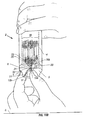
- Figure 10A illustrates container 2 being manually grasped and positioned in a substantially upside down position such that the test strips 30 contained in base 4 are moved into cover 6 when container 2 is in a substantially upside down position. Accordingly, if container 2 is originally in a substantially upright position, container 2 is turned or rotated such that it is in a substantially upside down position. As illustrated in Figure 10B, if container 2 includes a test strip holding mechanism 10, in this substantially upside down position contact element(s) 14 are positioned towards distal end 12b of channel 12, i.e., away from proximal opening 12a of channel 12.
- test strip 30a is selected or separated from the rest of the test strips 30. More specifically, the test strips 30 move into test strip selecting element 20 from base 4, which test strips 30 are then segregated by the continuously reduced diameter of the test strip selecting element 20, e.g., by a directing element 27 in certain instances.
- a single test strip 30a is ultimately segregated from the plurality 30 and selected by slot 22 so that at least a portion of the test strip 30a is positioned extending from slot 22 and a portion is positioned within slot 22 and within cavity 25, as shown in Figures 10A and 10B.
- a plurality of test strips 30 is moved from base 4 into second end 23 of continuously reduced diameter cavity 25 when the container 2 is positioned in a manner which causes the test strips 30 to move towards cover 6 and, as the test strips 30 move towards first end 21, the number of test strips gradually decreases due to the funnel-like portion or the tapered walls (and also due to a directing element if present) of cavity 25 of test strip selecting element 20.
- a single test strip 30a is separated from the remaining test strips 30 due to the funnel portion of test strip selecting element 20 and is selected by slot 22.
- the container 2 is gently agitated along the plane defined by - ⁇ to + ⁇ (see Figure 9B) to facilitate test strip selection.
- test strip 30a Once a single test strip 30a is selected within slot 22 of test strip selecting element 20, an individual simply handles the container 2 in an appropriate manner so that the selected test strip 30a may be used.
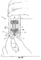
- the container 2 is simply positioned in a substantially horizontal position relative to the ground (the longitudinal axis L 2 of the device is positioned substantially parallel relative to the ground G) to such an extent to cause the plurality of test strips 30 to move back into base 4 while the selected test strip 30a is retained in slot 22 of test strip selecting element 20 as illustrated in Figure 10C.
- Base 4 is separated from cover 6 so as to provide access to the selected test strip 30a.
- the selected test strip 30a may be held in a fixed position in slot 22 using a test strip holding means, as described above. That is, a selected test strip 30a may be held in a fixed position in slot 22 by resiliently deforming one or more walls of cover 6 and/or by a test strip holding mechanism 10 that is gravity controlled.
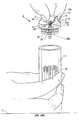
- one or more walls are engaged and resiliently deformed by urging them towards one another to hold a test strip 30a therebetween, as illustrated in Figure 10D, and container 2 is positioned so that the plurality of test strips 30 is moved back into base 4 (positioned in a substantially horizontal or substantially upright position relative to the ground), where the order of the steps may be reversed as will be apparent.
- an individual may grasp the resiliently deformable walls 17 and 18 at indents 5 of the cover 6 and apply a force thereto to urge resiliently deformable walls 17 and 18 together to an extent that they hold or pinch a test strip 30a between them.
- the force required to resiliently deform the walls to an extant so as to hold a test strip therebetween will vary depending on a variety of factors such as the material of construction of the walls, the dimensions of the test strip, etc. However, the force required will be minimal or slight to enable a dextrally impaired individual to easily use the device.
- test strip 30a is held in a fixed position by the resiliently deformed walls 17 and 18 of cover 6, cover 6 is removed or separated from base 4 such that the test strip 30a is held in cover 6 and access is provided thereto.
- test strip 30a is held in the cover 6 between the deformed walls 17 and 18 such that a portion of test strip 30a extends from slot 22 and a portion is positioned within slot 22 and more specifically within frustum-shaped cavity 25 of test strip selecting element 20.
- the portion that extends within cavity 25 is the area of the test strip 30a that provides contact with a meter.
- an individual may choose to leave the test strip 30a inside cover 6 by continuing to apply a force to the cover 6 so that the test strip 30a is held in place by the resiliently deformed walls 17 and 18, such that cover 6 serves as a handle or grip for test strip 30a while the tests trip is associated with a meter. In this manner, an individual does not have to touch the test strip 30a or try to manipulate it while mating it with a meter and during subsequent sample application.
- the portion of the test strip extending within cavity 25 may be the portion of the test strip where sample is applied so that a user need not remove the test strip from the cover in order to apply sample thereto and the cover may be used as a handle or grip in this instance as well.
- an individual may choose to remove the test strip 30a from the cover 6 anytime after cover 6 has been separated from base 4, i.e., before or after association with a meter, by simply grasping the test strip 30a from cover 6, such as by the edges of the test strip 30a, e.g., with fingers, tweezers and the like, and/or terminating the pressure applied to the resiliently deformed walls. Accordingly, the force applied to the walls 17 and 18 of the cover 6 to resiliently deform them is terminated so as to release the hold on the test strip 30a by the walls 17 and 18. The test strip 30a is then gently pulled or tugged to remove it from cover 6.
- container 2 is simply turned or rotated to a substantially upright position illustrated in Figure 10F from the substantially upside down position illustrated in Figure 10B.
- gravity slideably moves the one or more contact elements 14 in a direction towards open proximal end 12a of channel 12 such that they come to rest adjacent open end 12a.
- the distance the contact element 14 will protrude will be a distance sufficient to hold a test strip in a fixed position, where that distance will vary depending on a variety of factors such as the size, shape and weight of contact element 14, the number of contact elements positioned in channel 12, the dimensions of channel 12, etc.
- the force exerted by gravity-induced test strip holding mechanism 10 upon a portion of the test strip 30a to hold it in a fixed position in slot 22 will be a force sufficient to hold a test strip in a fixed position and will vary depending on a variety of factors such as the size of the test strip, the size, shape and weight and material of construction of the contact element(s) 14, and the like.
- test strip 30a is held in a fixed position by gravity-controlled test strip holding mechanism 10 such that the test strip 30a is held in cover 6 and access is provided thereto.
- an individual may grasp the indents 5 of the cover 6 and separate cover 6 from base 4.
- test strip 30a is held in cover 6, i.e., it is held by gravity-controlled test strip holding mechanism 10, such that a portion of test strip 30a is positioned in slot 22 and a portion is positioned within or extending from substantially frustum-shaped cavity 25 of test strip selecting element 20.
- the portion that extends within cavity 25 is the area of the test strip 30a that is contacted with a meter.
- an individual may choose to leave the test strip 30a inside cover 6, held in place by gravity -controlled test strip holding mechanism 10, such that cover 6 serves as a handle or grip for test strip 30a. In this manner, an individual does not have to touch test strip 30a or try to manipulate it while it is mated with a meter and during subsequent sample application.
- the portion of the test strip extending within cavity 25 may be the portion of the test strip where sample is applied so that a user need not remove the test strip from the cover in order to apply sample thereto and the cover may be used as a handle or grip in this instance as well.
- an individual may choose to remove the test strip 30a from cover 6 anytime after cover 6 has been separated from base 4, i.e., before or after association with a meter, by simply grasping the test strip 30a from the substantially upright cover 6, such as by the edges of the test strip 30a, e.g., with fingers, tweezers and the like, and gently pulling or tugging the test strip 30a to disengage it from gravity-controlled test strip holding mechanism 10 and/or by slightly turning or rotating cover 6 to a position such that the contact members 14 slideably move away from the test strip 30a, at which time the test strip 30 may be easily removed from cover 6.
- kits for practicing the subject methods are provided.
- the subject kits at least include one or more test strip dispensing devices of the subject invention. Oftentimes, a plurality of subject devices is included.
- the subject kits may also include one or more test strips, usually a plurality of test strips.
- the kits may further include a meter for automatically determining the presence and/or concentration of at least one analyte in a physiological sample applied to a test strip.
- the subject kits may further include an element for obtaining a physiological sample.
- the physiological sample is blood
- the subject kits may further include an element for obtaining a blood sample, such as a lance for sticking a finger, a lance actuation means, and the like.
- kits may include a calibration means for calibrating the instrument, e.g., a control solution or standard, e.g., a control solution that has a known analyte concentration such as a known glucose concentration.
- the kits may also include instructions for using the subject devices for dispensing test strips and may also include instruction for determining the presence and/or concentration of at least one analyte in a physiological sample applied to a test strip.
- the instructions may be printed on a substrate, such as paper or plastic, etc.
- the instructions may be present in the kits as a package insert, in the labeling of the container of the kit or components thereof (i.e., associated with the packaging or sub-packaging) etc.
- the instructions are present as an electronic storage data file present on a suitable computer readable storage medium, e.g., CD-ROM, diskette, etc.
- the above described invention provides a simple, quick and convenient way to dispense test strips.
- the above described invention provides a number of advantages, including, but not limited to, ease and low cost manufacture, minimal components, portability, ease of use, particularly for visually and dextrally impaired individuals, and minimal test strip damage from contaminants from an individual's hands.
- the subject invention represents a significant contribution to the art.
Landscapes
- Health & Medical Sciences (AREA)
- Engineering & Computer Science (AREA)
- Life Sciences & Earth Sciences (AREA)
- Biomedical Technology (AREA)
- Physics & Mathematics (AREA)
- Chemical & Material Sciences (AREA)
- Biochemistry (AREA)
- General Health & Medical Sciences (AREA)
- Molecular Biology (AREA)
- Urology & Nephrology (AREA)
- Optics & Photonics (AREA)
- Food Science & Technology (AREA)
- Hematology (AREA)
- Medicinal Chemistry (AREA)
- Biophysics (AREA)
- Analytical Chemistry (AREA)
- General Physics & Mathematics (AREA)
- Immunology (AREA)
- Pathology (AREA)
- Investigating Or Analysing Biological Materials (AREA)
- Automatic Analysis And Handling Materials Therefor (AREA)
- Investigating Or Analysing Materials By The Use Of Chemical Reactions (AREA)
Abstract
Description
Claims (10)
- A device or containing at least one test strip and dispensing a single test strip at a time, said device comprising:(a) a base; and(b) a cover, wherein said cover comprises at least one of:(i) a test strip selecting element comprising a continuously reduced cross-sectional area;(ii) a gravity-controlled test strip holding mechanism; and(iii) resiliently deformable walls.
- The device according to Claim 1, wherein said device comprises at least two of:(i) a test strip selecting element comprising a continuously reduced cross-sectional area;(ii) a gravity-controlled test strip holding mechanism; and(iii) resiliently deformable walls.
- The device according to Claim 1, wherein said device comprises all three of:(i) a test strip selecting element comprising a continuously reduced cross-sectional area;(ii) a gravity-controlled test strip holding mechanism; and(iii) resiliently deformable walls.
- The device according to any of claims 1, 2 or 3, wherein said test strip selecting element further comprises a directing element for directing said single test strip through said test strip selecting element.
- The device according to any of claims 1 to 4, wherein said device further comprises at least one test strip.
- A method for containing at least one test strip and selecting a single test strip at a time, said method comprising:whereby said single test strip is selected within said cover.(a) providing a device according to claim 5; and(b) positioning said device with respect to the ground to cause said single test strip to move from said base to said cover,
- The method according to claim 6, further comprising applying a sample to said selected test strip.
- The method according to claim 7, further comprising determining the concentration of at least one analyte in said sample.
- The method according to claim 7, further comprising inserting said selected test strip in a meter for automatically determining the concentration of said at least one analyte.
- A kit for containing at least one test strip and dispensing a single test strip at a time, said kit comprising:(a) at least one device according to any of claims 1 to 5; and(b) a substrate comprising instruction for using said at least one device.
Applications Claiming Priority (2)
| Application Number | Priority Date | Filing Date | Title |
|---|---|---|---|
| US10/116,086 US7172728B2 (en) | 2002-04-02 | 2002-04-02 | Test strip containers and methods of using the same |
| US116086 | 2002-04-02 |
Publications (2)
| Publication Number | Publication Date |
|---|---|
| EP1351055A2 true EP1351055A2 (en) | 2003-10-08 |
| EP1351055A3 EP1351055A3 (en) | 2005-05-04 |
Family
ID=28041077
Family Applications (1)
| Application Number | Title | Priority Date | Filing Date |
|---|---|---|---|
| EP03252059A Withdrawn EP1351055A3 (en) | 2002-04-02 | 2003-04-01 | Test strip containers and methods of using the same |
Country Status (7)
| Country | Link |
|---|---|
| US (1) | US7172728B2 (en) |
| EP (1) | EP1351055A3 (en) |
| JP (1) | JP2003337136A (en) |
| CN (1) | CN1277123C (en) |
| CA (1) | CA2424463A1 (en) |
| IL (1) | IL154971A0 (en) |
| TW (1) | TW200402387A (en) |
Cited By (4)
| Publication number | Priority date | Publication date | Assignee | Title |
|---|---|---|---|---|
| WO2010002741A1 (en) | 2008-07-03 | 2010-01-07 | Abbott Diabetes Care, Inc. | Strip vial and cap |
| US8062235B2 (en) | 2005-07-19 | 2011-11-22 | Ihq Innovation Headquarters Oy | Health monitoring device, device modules and method |
| EP2549270A2 (en) * | 2011-07-22 | 2013-01-23 | Bayer Healthcare LLC | Biosensor desiccant system having enhanced measurement performance |
| FR3100123A1 (en) * | 2019-09-03 | 2021-03-05 | Toda Pharma | Device for testing biological fluid, especially saliva testing |
Families Citing this family (102)
| Publication number | Priority date | Publication date | Assignee | Title |
|---|---|---|---|---|
| US6391005B1 (en) | 1998-03-30 | 2002-05-21 | Agilent Technologies, Inc. | Apparatus and method for penetration with shaft having a sensor for sensing penetration depth |
| US8641644B2 (en) | 2000-11-21 | 2014-02-04 | Sanofi-Aventis Deutschland Gmbh | Blood testing apparatus having a rotatable cartridge with multiple lancing elements and testing means |
| US7981056B2 (en) | 2002-04-19 | 2011-07-19 | Pelikan Technologies, Inc. | Methods and apparatus for lancet actuation |
| US7041068B2 (en) | 2001-06-12 | 2006-05-09 | Pelikan Technologies, Inc. | Sampling module device and method |
| US9226699B2 (en) | 2002-04-19 | 2016-01-05 | Sanofi-Aventis Deutschland Gmbh | Body fluid sampling module with a continuous compression tissue interface surface |
| US7344507B2 (en) | 2002-04-19 | 2008-03-18 | Pelikan Technologies, Inc. | Method and apparatus for lancet actuation |
| US9427532B2 (en) | 2001-06-12 | 2016-08-30 | Sanofi-Aventis Deutschland Gmbh | Tissue penetration device |
| WO2002100460A2 (en) | 2001-06-12 | 2002-12-19 | Pelikan Technologies, Inc. | Electric lancet actuator |
| CA2448902C (en) | 2001-06-12 | 2010-09-07 | Pelikan Technologies, Inc. | Self optimizing lancing device with adaptation means to temporal variations in cutaneous properties |
| US9795747B2 (en) | 2010-06-02 | 2017-10-24 | Sanofi-Aventis Deutschland Gmbh | Methods and apparatus for lancet actuation |
| AU2002348683A1 (en) | 2001-06-12 | 2002-12-23 | Pelikan Technologies, Inc. | Method and apparatus for lancet launching device integrated onto a blood-sampling cartridge |
| US8337419B2 (en) | 2002-04-19 | 2012-12-25 | Sanofi-Aventis Deutschland Gmbh | Tissue penetration device |
| US8702624B2 (en) | 2006-09-29 | 2014-04-22 | Sanofi-Aventis Deutschland Gmbh | Analyte measurement device with a single shot actuator |
| US7491178B2 (en) | 2002-04-19 | 2009-02-17 | Pelikan Technologies, Inc. | Method and apparatus for penetrating tissue |
| US8579831B2 (en) | 2002-04-19 | 2013-11-12 | Sanofi-Aventis Deutschland Gmbh | Method and apparatus for penetrating tissue |
| US7547287B2 (en) | 2002-04-19 | 2009-06-16 | Pelikan Technologies, Inc. | Method and apparatus for penetrating tissue |
| US7226461B2 (en) | 2002-04-19 | 2007-06-05 | Pelikan Technologies, Inc. | Method and apparatus for a multi-use body fluid sampling device with sterility barrier release |
| US9314194B2 (en) | 2002-04-19 | 2016-04-19 | Sanofi-Aventis Deutschland Gmbh | Tissue penetration device |
| US7229458B2 (en) | 2002-04-19 | 2007-06-12 | Pelikan Technologies, Inc. | Method and apparatus for penetrating tissue |
| US8267870B2 (en) | 2002-04-19 | 2012-09-18 | Sanofi-Aventis Deutschland Gmbh | Method and apparatus for body fluid sampling with hybrid actuation |
| US7674232B2 (en) | 2002-04-19 | 2010-03-09 | Pelikan Technologies, Inc. | Method and apparatus for penetrating tissue |
| US7892185B2 (en) | 2002-04-19 | 2011-02-22 | Pelikan Technologies, Inc. | Method and apparatus for body fluid sampling and analyte sensing |
| US8360992B2 (en) | 2002-04-19 | 2013-01-29 | Sanofi-Aventis Deutschland Gmbh | Method and apparatus for penetrating tissue |
| US7901362B2 (en) | 2002-04-19 | 2011-03-08 | Pelikan Technologies, Inc. | Method and apparatus for penetrating tissue |
| US7331931B2 (en) | 2002-04-19 | 2008-02-19 | Pelikan Technologies, Inc. | Method and apparatus for penetrating tissue |
| US7232451B2 (en) | 2002-04-19 | 2007-06-19 | Pelikan Technologies, Inc. | Method and apparatus for penetrating tissue |
| US7892183B2 (en) | 2002-04-19 | 2011-02-22 | Pelikan Technologies, Inc. | Method and apparatus for body fluid sampling and analyte sensing |
| US9795334B2 (en) | 2002-04-19 | 2017-10-24 | Sanofi-Aventis Deutschland Gmbh | Method and apparatus for penetrating tissue |
| US8784335B2 (en) | 2002-04-19 | 2014-07-22 | Sanofi-Aventis Deutschland Gmbh | Body fluid sampling device with a capacitive sensor |
| US8221334B2 (en) | 2002-04-19 | 2012-07-17 | Sanofi-Aventis Deutschland Gmbh | Method and apparatus for penetrating tissue |
| US7909778B2 (en) | 2002-04-19 | 2011-03-22 | Pelikan Technologies, Inc. | Method and apparatus for penetrating tissue |
| US7297122B2 (en) | 2002-04-19 | 2007-11-20 | Pelikan Technologies, Inc. | Method and apparatus for penetrating tissue |
| US7976476B2 (en) | 2002-04-19 | 2011-07-12 | Pelikan Technologies, Inc. | Device and method for variable speed lancet |
| US9248267B2 (en) | 2002-04-19 | 2016-02-02 | Sanofi-Aventis Deustchland Gmbh | Tissue penetration device |
| US20030223906A1 (en) * | 2002-06-03 | 2003-12-04 | Mcallister Devin | Test strip container system |
| US8574895B2 (en) | 2002-12-30 | 2013-11-05 | Sanofi-Aventis Deutschland Gmbh | Method and apparatus using optical techniques to measure analyte levels |
| EP2238892A3 (en) | 2003-05-30 | 2011-02-09 | Pelikan Technologies Inc. | Apparatus for body fluid sampling |
| ES2490740T3 (en) | 2003-06-06 | 2014-09-04 | Sanofi-Aventis Deutschland Gmbh | Apparatus for blood fluid sampling and analyte detection |
| WO2006001797A1 (en) | 2004-06-14 | 2006-01-05 | Pelikan Technologies, Inc. | Low pain penetrating |
| EP1671096A4 (en) | 2003-09-29 | 2009-09-16 | Pelikan Technologies Inc | METHOD AND APPARATUS FOR AN IMPROVED SAMPLING INTERFERENCE DEVICE |
| EP1680014A4 (en) | 2003-10-14 | 2009-01-21 | Pelikan Technologies Inc | METHOD AND APPARATUS PROVIDING A VARIABLE USER INTERFACE |
| US8394337B2 (en) | 2003-12-31 | 2013-03-12 | Nipro Diagnostics, Inc. | Test strip container with integrated meter |
| US8147426B2 (en) | 2003-12-31 | 2012-04-03 | Nipro Diagnostics, Inc. | Integrated diagnostic test system |
| US9012232B2 (en) | 2005-07-15 | 2015-04-21 | Nipro Diagnostics, Inc. | Diagnostic strip coding system and related methods of use |
| US7822454B1 (en) | 2005-01-03 | 2010-10-26 | Pelikan Technologies, Inc. | Fluid sampling device with improved analyte detecting member configuration |
| WO2005065414A2 (en) | 2003-12-31 | 2005-07-21 | Pelikan Technologies, Inc. | Method and apparatus for improving fluidic flow and sample capture |
| US8394328B2 (en) * | 2003-12-31 | 2013-03-12 | Nipro Diagnostics, Inc. | Test strip container with integrated meter having strip coding capability |
| US8828203B2 (en) | 2004-05-20 | 2014-09-09 | Sanofi-Aventis Deutschland Gmbh | Printable hydrogels for biosensors |
| USD506832S1 (en) | 2004-06-02 | 2005-06-28 | Home Diagnostics, Inc. | Meter for an integrated diagnostic test system |
| USD507657S1 (en) | 2004-06-02 | 2005-07-19 | Home Diagnostics, Inc. | Meter for an integrated diagnostic test system |
| US9775553B2 (en) | 2004-06-03 | 2017-10-03 | Sanofi-Aventis Deutschland Gmbh | Method and apparatus for a fluid sampling device |
| EP1765194A4 (en) | 2004-06-03 | 2010-09-29 | Pelikan Technologies Inc | METHOD AND APPARATUS FOR MANUFACTURING A DEVICE FOR SAMPLING LIQUIDS |
| US7582262B2 (en) | 2004-06-18 | 2009-09-01 | Roche Diagnostics Operations, Inc. | Dispenser for flattened articles |
| US8652831B2 (en) | 2004-12-30 | 2014-02-18 | Sanofi-Aventis Deutschland Gmbh | Method and apparatus for analyte measurement test time |
| USD561904S1 (en) | 2005-01-31 | 2008-02-12 | Home Diagnostics, Inc. | Meter for an integrated diagnostic test system |
| US8016154B2 (en) * | 2005-05-25 | 2011-09-13 | Lifescan, Inc. | Sensor dispenser device and method of use |
| US20060275890A1 (en) * | 2005-06-06 | 2006-12-07 | Home Diagnostics, Inc. | Method of manufacturing a disposable diagnostic meter |
| US7955856B2 (en) | 2005-07-15 | 2011-06-07 | Nipro Diagnostics, Inc. | Method of making a diagnostic test strip having a coding system |
| US8999125B2 (en) | 2005-07-15 | 2015-04-07 | Nipro Diagnostics, Inc. | Embedded strip lot autocalibration |
| US20070080093A1 (en) * | 2005-10-11 | 2007-04-12 | Agamatrix, Inc. | Vial for test strips |
| US11559810B2 (en) | 2006-03-13 | 2023-01-24 | Trividia Health, Inc. | Method and apparatus for coding diagnostic meters |
| US8388906B2 (en) * | 2006-03-13 | 2013-03-05 | Nipro Diagnostics, Inc. | Apparatus for dispensing test strips |
| US8940246B2 (en) | 2006-03-13 | 2015-01-27 | Nipro Diagnostics, Inc. | Method and apparatus for coding diagnostic meters |
| US8388905B2 (en) * | 2006-03-13 | 2013-03-05 | Nipro Diagnostics, Inc. | Method and apparatus for coding diagnostic meters |
| US7597853B2 (en) * | 2006-05-09 | 2009-10-06 | Becton, Dickinson And Company | Method and apparatus for dispensing diagnostic test strips |
| US8001825B2 (en) * | 2007-11-30 | 2011-08-23 | Lifescan, Inc. | Auto-calibrating metering system and method of use |
| EP2265324B1 (en) | 2008-04-11 | 2015-01-28 | Sanofi-Aventis Deutschland GmbH | Integrated analyte measurement system |
| US7896703B2 (en) * | 2008-07-17 | 2011-03-01 | Abbott Diabetes Care Inc. | Strip connectors for measurement devices |
| US7946866B2 (en) * | 2008-08-28 | 2011-05-24 | Abbott Diabetes Care Inc. | Apparatus for preventing electrical shock in devices |
| KR20110079701A (en) * | 2008-09-30 | 2011-07-07 | 멘나이 메디컬 테크놀로지즈 리미티드 | Sample metrology systems |
| US9375169B2 (en) | 2009-01-30 | 2016-06-28 | Sanofi-Aventis Deutschland Gmbh | Cam drive for managing disposable penetrating member actions with a single motor and motor and control system |
| US20100268053A1 (en) * | 2009-04-15 | 2010-10-21 | Abbott Diabetes Care Inc. | Method and Device for Detecting USB Cable Connection |
| US8236254B2 (en) * | 2009-05-14 | 2012-08-07 | Abbott Diabetes Care Inc. | Cap-linked test strip carrier for vial augmentation |
| USD634440S1 (en) * | 2009-06-24 | 2011-03-15 | Oy Medix Biochemica Ab | Container portion of a test strip unit |
| US20110127175A1 (en) * | 2009-11-30 | 2011-06-02 | Roche Diagnostics Operations, Inc. | Test strip container with expandable insert and methods of manufacturing and utilization thereof |
| US8066957B2 (en) | 2009-12-23 | 2011-11-29 | Roche Diagnostics Operations, Inc. | Easy strip access primary container and methods of manufacturing and utilization thereof |
| US8844725B2 (en) * | 2010-01-20 | 2014-09-30 | Roche Diagnostics Operations, Inc. | Test strip container with strip retainer and methods of manufacturing and utilization thereof |
| US20110182785A1 (en) | 2010-01-22 | 2011-07-28 | Roche Diagnostics Operations, Inc. | Flat Pop-Up Primary Container And Methods of Manufacturing And Utilization Thereof |
| CN105603045B (en) * | 2010-01-22 | 2021-05-14 | 安晟信医疗科技控股公司 | Accuracy improving desiccant |
| US9233788B2 (en) | 2010-01-22 | 2016-01-12 | Bayer Healthcare Llc | Biosensor desiccant system having enhanced measurement performance |
| GB201005357D0 (en) | 2010-03-30 | 2010-05-12 | Menai Medical Technologies Ltd | Sampling plate |
| GB201005359D0 (en) | 2010-03-30 | 2010-05-12 | Menai Medical Technologies Ltd | Sampling plate |
| US8965476B2 (en) | 2010-04-16 | 2015-02-24 | Sanofi-Aventis Deutschland Gmbh | Tissue penetration device |
| US8919607B2 (en) * | 2010-04-16 | 2014-12-30 | Abbott Diabetes Care Inc. | Analyte test strip vial |
| US8757386B2 (en) * | 2010-09-30 | 2014-06-24 | Abbott Diabetes Care Inc. | Analyte test strip containers and inserts |
| EP2633310A4 (en) * | 2010-10-26 | 2016-02-24 | Abbott Diabetes Care Inc | Analyte measurement devices and systems, and components and methods related thereto |
| US9713440B2 (en) | 2010-12-08 | 2017-07-25 | Abbott Diabetes Care Inc. | Modular analyte measurement systems, modular components thereof and related methods |
| US9341613B2 (en) | 2011-02-07 | 2016-05-17 | Kevin G. Sawa | Device for singulating and dispensing rigid and semi-rigid strips |
| US8475733B2 (en) * | 2011-08-04 | 2013-07-02 | Cilag Gmbh International | Hand-held test meter and analytical test strip cartridge assembly with desiccant vial |
| USD680454S1 (en) | 2011-10-25 | 2013-04-23 | Abbott Diabetes Care Inc. | Analyte meter and strip port |
| US9914126B2 (en) | 2011-11-28 | 2018-03-13 | Roche Diabetes Care, Inc. | Storage container for biosensor test elements |
| WO2013157242A1 (en) | 2012-04-19 | 2013-10-24 | パナソニック株式会社 | Sensor storage container |
| WO2015066673A1 (en) * | 2013-11-04 | 2015-05-07 | Csp Technologies, Inc. | Container with singulating mechanism |
| CN105044070B (en) * | 2015-08-18 | 2017-02-22 | 上海微银生物技术有限公司 | Tear glucose detection device |
| CA3015222A1 (en) * | 2016-03-02 | 2017-09-08 | Becton, Dickinson And Company | Packaging and devices to access screw-top containers in automated systems |
| US20180024073A1 (en) * | 2016-07-21 | 2018-01-25 | Ronald Schornstein | Reach-extended test strip |
| CN107512472B (en) * | 2017-09-14 | 2023-02-10 | 国网吉林省电力有限公司电力科学研究院 | Dust-free filter membrane storage box for dust sampling and using method thereof |
| US11857169B1 (en) * | 2018-04-23 | 2024-01-02 | George Mason Research Foundation, Inc. | Collapsible fluid collection system for point-of-care diagnostics |
| CN108871908B9 (en) * | 2018-09-06 | 2024-07-26 | 杭州优思达生物技术股份有限公司 | Biological sample processing device |
| US20210403226A1 (en) * | 2020-06-30 | 2021-12-30 | James B. Babcock | Flip-top vial with shake-out strip dispenser and molded desiccant |
| US11517896B2 (en) | 2020-08-14 | 2022-12-06 | Luna Pharmaceuticals, Inc. | Test strip holder |
| CN116101607B (en) * | 2023-04-13 | 2023-06-16 | 佳木斯大学 | Storage for disposable reagent strips |
Family Cites Families (41)
| Publication number | Priority date | Publication date | Assignee | Title |
|---|---|---|---|---|
| DE249333C (en) * | 1911-08-18 | 1912-07-16 | ||
| US1744195A (en) * | 1928-10-11 | 1930-01-21 | Alland Maurice | Cigarette dispenser and humidifier |
| US2641358A (en) | 1950-03-14 | 1953-06-09 | Worcester Moulded Plastics Com | Razor blade dispenser |
| US3393831A (en) | 1966-11-25 | 1968-07-23 | Scient Plastic Corp | Glass slide dispenser |
| US3589557A (en) | 1969-04-03 | 1971-06-29 | Miles Lab | Slide dispenser |
| USD249333S (en) * | 1976-06-07 | 1978-09-12 | Warner-Lambert Company | Candy dispenser |
| USRE30895E (en) | 1976-09-03 | 1982-04-06 | Filter paper dispenser | |
| US4114780A (en) | 1976-12-02 | 1978-09-19 | Shaul Sharon | Combination industrial razor blade dispenser and used blade receiver |
| US4173226A (en) * | 1977-11-10 | 1979-11-06 | Alza Corporation | Device for administering solid drug particles to an eye |
| US4190420A (en) | 1978-06-05 | 1980-02-26 | Eastman Kodak Company | Container for dispensing articles to an automated analyzer |
| US4187077A (en) | 1978-06-05 | 1980-02-05 | Eastman Kodak Company | Container with article positioning element for dispensing reagent coated slides to an automated analyzer |
| JPS6142107Y2 (en) | 1979-11-30 | 1986-11-29 | ||
| EP0270868B1 (en) | 1984-06-28 | 1991-01-30 | Roche Diagnostics GmbH | Container for diagnostic indicators |
| US4817820A (en) | 1987-08-27 | 1989-04-04 | Miles Inc. | Slide dispenser for a reagent cannister |
| US4833088A (en) | 1987-09-25 | 1989-05-23 | Miles Inc. | Reagent strip handling mechanism |
| US4911344A (en) | 1988-03-23 | 1990-03-27 | Tek-Aids Inc. | Strip dispenser box |
| US5249737A (en) | 1991-09-09 | 1993-10-05 | Ecolab Inc. | Method for dispensing moisture-sensitive unit dose packages |
| GB9223016D0 (en) | 1992-11-03 | 1992-12-16 | Environmental And Medical Prod | Electrochemical sensor |
| DE59410388D1 (en) | 1993-04-23 | 2004-10-21 | Roche Diagnostics Gmbh | Floppy disk with test elements arranged in a circle |
| DE4313253A1 (en) | 1993-04-23 | 1994-10-27 | Boehringer Mannheim Gmbh | System for analyzing the contents of liquid samples |
| US5871452A (en) | 1993-07-02 | 1999-02-16 | Rachman Scientific, Inc. | Skin test applicator |
| US5534224A (en) | 1993-07-16 | 1996-07-09 | Fuji Photo Film Co., Ltd. | Chemical analysis film cartridge |
| US5409133A (en) | 1994-02-17 | 1995-04-25 | Allway Tools, Inc. | Razor blade dispenser |
| US5630986A (en) | 1995-01-13 | 1997-05-20 | Bayer Corporation | Dispensing instrument for fluid monitoring sensors |
| US5575403A (en) | 1995-01-13 | 1996-11-19 | Bayer Corporation | Dispensing instrument for fluid monitoring sensors |
| FR2733745B1 (en) | 1995-05-02 | 1997-07-04 | Asulab Sa | IMPROVED APPARATUS FOR THE DISTRIBUTION OF SUCCESSIVE AREAS OF A CONSUMABLE BAND |
| US5510266A (en) | 1995-05-05 | 1996-04-23 | Bayer Corporation | Method and apparatus of handling multiple sensors in a glucose monitoring instrument system |
| US5678729A (en) * | 1995-09-14 | 1997-10-21 | Raymond; Dorothy | Target rim and tip for containers |
| US5759010A (en) | 1995-11-06 | 1998-06-02 | Jacobs; Merrit Nyles | Sealed cartridge to improve chemistry stability of test elements |
| DE19715031A1 (en) | 1997-04-11 | 1998-10-15 | Boehringer Mannheim Gmbh | Magazine for storing test elements |
| US5939329A (en) * | 1997-05-14 | 1999-08-17 | Serim Research Corporation | Test strip incubation device and method |
| US5971941A (en) | 1997-12-04 | 1999-10-26 | Hewlett-Packard Company | Integrated system and method for sampling blood and analysis |
| US6036924A (en) | 1997-12-04 | 2000-03-14 | Hewlett-Packard Company | Cassette of lancet cartridges for sampling blood |
| EP1059882B1 (en) | 1998-03-06 | 2007-10-17 | SPECTRX, Inc. | Integrated tissue poration, fluid harvesting and analysis device |
| DE29905581U1 (en) | 1999-03-26 | 1999-06-10 | Winter, Lieselotte, 69234 Dielheim | Announcement for events with horses |
| DE29905561U1 (en) * | 1999-03-27 | 1999-09-09 | Odenwald, Gottfried, Dr.med., 89518 Heidenheim | Storage box and disposal box for blood test strips |
| EP1216416B1 (en) | 1999-09-27 | 2006-02-15 | Hypoguard Limited | Test device |
| US6228100B1 (en) | 1999-10-25 | 2001-05-08 | Steven Schraga | Multi-use lancet device |
| AU2001234137A1 (en) | 2000-02-23 | 2001-09-03 | Arkray, Inc. | Sensor cartridge, sensor feeder, and measuring instrument |
| GB0017737D0 (en) | 2000-07-20 | 2000-09-06 | Hypoguard Limited | Test device |
| US6485918B1 (en) * | 2001-07-02 | 2002-11-26 | Packard Bioscience Corporation | Method and apparatus for incubation of a liquid reagent and target spots on a microarray substrate |
-
2002
- 2002-04-02 US US10/116,086 patent/US7172728B2/en not_active Expired - Lifetime
-
2003
- 2003-03-18 IL IL15497103A patent/IL154971A0/en not_active IP Right Cessation
- 2003-03-31 CA CA002424463A patent/CA2424463A1/en not_active Abandoned
- 2003-04-01 TW TW092107331A patent/TW200402387A/en unknown
- 2003-04-01 EP EP03252059A patent/EP1351055A3/en not_active Withdrawn
- 2003-04-01 JP JP2003098352A patent/JP2003337136A/en active Pending
- 2003-04-01 CN CNB031077943A patent/CN1277123C/en not_active Expired - Fee Related
Cited By (5)
| Publication number | Priority date | Publication date | Assignee | Title |
|---|---|---|---|---|
| US8062235B2 (en) | 2005-07-19 | 2011-11-22 | Ihq Innovation Headquarters Oy | Health monitoring device, device modules and method |
| WO2010002741A1 (en) | 2008-07-03 | 2010-01-07 | Abbott Diabetes Care, Inc. | Strip vial and cap |
| EP2549270A2 (en) * | 2011-07-22 | 2013-01-23 | Bayer Healthcare LLC | Biosensor desiccant system having enhanced measurement performance |
| FR3100123A1 (en) * | 2019-09-03 | 2021-03-05 | Toda Pharma | Device for testing biological fluid, especially saliva testing |
| WO2021044086A1 (en) * | 2019-09-03 | 2021-03-11 | Toda Pharma | Biological fluid test device, in particular a saliva test device |
Also Published As
| Publication number | Publication date |
|---|---|
| TW200402387A (en) | 2004-02-16 |
| IL154971A0 (en) | 2003-10-31 |
| CA2424463A1 (en) | 2003-10-02 |
| US7172728B2 (en) | 2007-02-06 |
| CN1277123C (en) | 2006-09-27 |
| EP1351055A3 (en) | 2005-05-04 |
| US20030185708A1 (en) | 2003-10-02 |
| JP2003337136A (en) | 2003-11-28 |
| CN1448720A (en) | 2003-10-15 |
Similar Documents
| Publication | Publication Date | Title |
|---|---|---|
| US7172728B2 (en) | Test strip containers and methods of using the same | |
| EP1369686B1 (en) | Analyte concentration determination meters and methods of using the same | |
| EP1329395B1 (en) | Test strip dispenser | |
| EP1362801B1 (en) | Test strip containers and methods of using the same | |
| JP5144529B2 (en) | sensor | |
| RU2309673C2 (en) | Container set for test-lags | |
| US9410961B2 (en) | Methods of indexing a test-sensor cartridge | |
| US20070259431A1 (en) | Optical Sensor and Methods of Making It | |
| HK1056395A (en) | Test strip containers and methods of using the same | |
| HK1058703B (en) | Analyte concentration determination meters and methods of using the same | |
| HK1054725B (en) | Test strip dispenser | |
| HK1057355B (en) | Test strip containers and methods of using the same | |
| US8501111B2 (en) | Small volume and fast acting optical analyte sensor | |
| AU2003204245A1 (en) | Test strip container system | |
| HK1058471B (en) | Test strip container system |
Legal Events
| Date | Code | Title | Description |
|---|---|---|---|
| PUAI | Public reference made under article 153(3) epc to a published international application that has entered the european phase |
Free format text: ORIGINAL CODE: 0009012 |
|
| AK | Designated contracting states |
Kind code of ref document: A2 Designated state(s): AT BE BG CH CY CZ DE DK EE ES FI FR GB GR HU IE IT LI LU MC NL PT RO SE SI SK TR |
|
| AX | Request for extension of the european patent |
Extension state: AL LT LV MK |
|
| PUAL | Search report despatched |
Free format text: ORIGINAL CODE: 0009013 |
|
| AK | Designated contracting states |
Kind code of ref document: A3 Designated state(s): AT BE BG CH CY CZ DE DK EE ES FI FR GB GR HU IE IT LI LU MC NL PT RO SE SI SK TR |
|
| AX | Request for extension of the european patent |
Extension state: AL LT LV MK |
|
| 17P | Request for examination filed |
Effective date: 20051014 |
|
| AKX | Designation fees paid |
Designated state(s): BE DE FR GB IT NL |
|
| 17Q | First examination report despatched |
Effective date: 20060717 |
|
| 17Q | First examination report despatched |
Effective date: 20060717 |
|
| GRAP | Despatch of communication of intention to grant a patent |
Free format text: ORIGINAL CODE: EPIDOSNIGR1 |
|
| STAA | Information on the status of an ep patent application or granted ep patent |
Free format text: STATUS: THE APPLICATION IS DEEMED TO BE WITHDRAWN |
|
| 18D | Application deemed to be withdrawn |
Effective date: 20071114 |
|
| REG | Reference to a national code |
Ref country code: HK Ref legal event code: WD Ref document number: 1056395 Country of ref document: HK |