EP1350946A2 - High pressure fuel supply device having plating layer and manufacturing method thereof - Google Patents
High pressure fuel supply device having plating layer and manufacturing method thereof Download PDFInfo
- Publication number
- EP1350946A2 EP1350946A2 EP03007790A EP03007790A EP1350946A2 EP 1350946 A2 EP1350946 A2 EP 1350946A2 EP 03007790 A EP03007790 A EP 03007790A EP 03007790 A EP03007790 A EP 03007790A EP 1350946 A2 EP1350946 A2 EP 1350946A2
- Authority
- EP
- European Patent Office
- Prior art keywords
- connecting portion
- wall surface
- high pressure
- supply device
- bar member
- Prior art date
- Legal status (The legal status is an assumption and is not a legal conclusion. Google has not performed a legal analysis and makes no representation as to the accuracy of the status listed.)
- Withdrawn
Links
Images


Classifications
-
- F—MECHANICAL ENGINEERING; LIGHTING; HEATING; WEAPONS; BLASTING
- F02—COMBUSTION ENGINES; HOT-GAS OR COMBUSTION-PRODUCT ENGINE PLANTS
- F02M—SUPPLYING COMBUSTION ENGINES IN GENERAL WITH COMBUSTIBLE MIXTURES OR CONSTITUENTS THEREOF
- F02M55/00—Fuel-injection apparatus characterised by their fuel conduits or their venting means; Arrangements of conduits between fuel tank and pump F02M37/00
- F02M55/02—Conduits between injection pumps and injectors, e.g. conduits between pump and common-rail or conduits between common-rail and injectors
- F02M55/025—Common rails
-
- F—MECHANICAL ENGINEERING; LIGHTING; HEATING; WEAPONS; BLASTING
- F02—COMBUSTION ENGINES; HOT-GAS OR COMBUSTION-PRODUCT ENGINE PLANTS
- F02M—SUPPLYING COMBUSTION ENGINES IN GENERAL WITH COMBUSTIBLE MIXTURES OR CONSTITUENTS THEREOF
- F02M55/00—Fuel-injection apparatus characterised by their fuel conduits or their venting means; Arrangements of conduits between fuel tank and pump F02M37/00
- F02M55/004—Joints; Sealings
- F02M55/005—Joints; Sealings for high pressure conduits, e.g. connected to pump outlet or to injector inlet
-
- Y—GENERAL TAGGING OF NEW TECHNOLOGICAL DEVELOPMENTS; GENERAL TAGGING OF CROSS-SECTIONAL TECHNOLOGIES SPANNING OVER SEVERAL SECTIONS OF THE IPC; TECHNICAL SUBJECTS COVERED BY FORMER USPC CROSS-REFERENCE ART COLLECTIONS [XRACs] AND DIGESTS
- Y10—TECHNICAL SUBJECTS COVERED BY FORMER USPC
- Y10T—TECHNICAL SUBJECTS COVERED BY FORMER US CLASSIFICATION
- Y10T29/00—Metal working
- Y10T29/49—Method of mechanical manufacture
- Y10T29/49405—Valve or choke making
- Y10T29/49412—Valve or choke making with assembly, disassembly or composite article making
- Y10T29/49416—Valve or choke making with assembly, disassembly or composite article making with material shaping or cutting
- Y10T29/49421—Valve or choke making with assembly, disassembly or composite article making with material shaping or cutting including metallurgical bonding
Definitions
- the present invention relates to a high pressure fuel supply device of a pressure accumulating type.
- a high pressure fuel supply device of a pressure accumulating type has been proposed as a high pressure fuel supply device of, for example, a diesel engine.
- high pressure fuel is accumulated in a pressurized state in a pressure accumulation chamber formed in a pressure accumulator vessel and is supplied to each corresponding fuel injection device.
- Fuel passages are also formed in the pressure accumulator vessel. Each fuel passage is communicated with the accumulation chamber and conducts fuel to the accumulation chamber or conducts fuel from the accumulation chamber.
- An axis of the accumulation chamber is generally perpendicular to an axis of each fuel passage. Thus, an edged corner is formed in a connection between the accumulation chamber and the corresponding fuel passage.
- Japanese Unexamined Patent Publication No. 2000-73908 in order to address the above disadvantage, for example, there has been proposed a high pressure fuel supply device, which has a pressure accumulator vessel that includes an inner member and an outer member.
- the inner member is press fitted into the outer member to apply compressive pre-stress to the inner member to reduce tensile stress applied from the fuel in the accumulation chamber to the inner member.
- the accumulator vessel since the accumulator vessel includes the outer member and the inner member, the number of components is disadvantageously increased, and the total manufacturing time of the high pressure fuel supply device is also disadvantageously increased.
- the chamfered section which is chamfered through the electrolytic process, has a rough surface, which likely causes localized concentration of stress in the chamfered section.
- the surface of the corner is smoothed through an abrasive flow machining process applied to the interior of the accumulator vessel after each corner is chamfered thorough the electrolytic process.
- the abrasive flow machining process disadvantageously requires a relatively long processing time.
- a high pressure fuel supply device having a pressure accumulator vessel that includes a pressure accumulation chamber, a fuel passage and a chamfered section.
- the pressure accumulation chamber extends in an axial direction of the pressure accumulator vessel.
- the fuel passage fluidly communicates between the accumulation chamber and an outside of the pressure accumulator vessel.
- the chamfered section is formed in a connection between the accumulation chamber and the fuel passage.
- An inner plated part which includes a plating layer, is formed along a wall surface of the accumulation chamber, a wall surface of the fuel passage and a wall surface of the chamfered section.
- a manufacturing method of a high pressure fuel supply device to which an external fuel pipe is joined.
- an axial hole, a branched hole and a chamfered section are first formed in a bar member.
- the axial hole extends in an axial direction of the bar member.
- the branched hole fluidly communicates between the axial hole and an outside of the bar member.
- the chamfered section is formed in a connection between the axial hole and the branched hole.
- a connecting portion and a sealing portion are formed in the bar member.
- the connecting portion is formed to join with the external fuel pipe in such a manner that the fuel pipe is securely held by the connecting portion and is fluidly communicated with the branched hole.
- the sealing portion is formed adjacent to the connecting portion to fluid-tightly engage with the fuel pipe.
- a removable sealing member is installed in the bar member in such a manner that the sealing member engages the connecting portion and the sealing portion to fluid-tightly separate the axial hole and the branched hole from the connecting portion and the sealing portion.
- a plated part which includes a plating layer, is formed along a wall surface of the axial hole, a wall surface of the branched hole and a wall surface of the chamfered section.
- a manufacturing method of a high pressure fuel supply device to which an external fuel pipe is joined.
- an axial hole, a branched hole and a chamfered section are formed in a bar member.
- the axial hole extends in an axial direction of the bar member.
- the branched hole fluidly communicates between the axial hole and an outside of the bar member.
- the chamfered section is formed in a connection between the axial hole and the branched hole.
- a plated part which includes a plating layer, is formed along a wall surface of the axial hole, a wall surface of the branched hole and a wall surface of the chamfered section.
- a connecting portion and a sealing portion are formed in the bar member that includes the inner plated part.
- the connecting portion is formed to join with the external fuel pipe in such a manner that the fuel pipe is securely held by the connecting portion and is fluidly communicated with the branched hole.
- the sealing portion is formed adjacent to the connecting portion to fluid-tightly engage with the fuel pipe.
- FIG. 1 shows a high pressure fuel supply device according to a first embodiment of the present invention.
- the high pressure fuel supply device 1 accumulates high pressure fuel of a predetermined pressure, which is supplied from a high pressure pump (not shown), and supplies the high pressure fuel to injectors (not shown).
- the high pressure fuel supply device 1 includes a pressure accumulator vessel 10 and a sealing plug 20.
- the accumulator vessel 10 includes a plurality of fuel inlets 11 and a plurality of fuel outlets 12.
- the fuel inlets 11 are connected to the high pressure pump (not shown), and fuel is supplied from the high pressure pump to the fuel inlets 11.
- the fuel outlets 12 are connected to the corresponding injectors (not shown), and fuel accumulated in the accumulator vessel 10 is discharged to the injectors through the fuel outlets 12.
- the accumulator vessel 10 further includes a pressure accumulation chamber 13 and a plurality of fuel passages 14.
- the accumulation chamber 13 is defined by an inner wall 10a of the accumulator vessel 10 and an inner wall 20a of an end of the sealing plug 20, which is arranged in an open end of the accumulator vessel 10.
- the fuel passage 14 is communicated with the accumulation chamber 13 in a radial direction of the accumulator vessel 10.
- a chamfered section 15 is provided in a connection formed in the inner wall 10a of the accumulator vessel 10 between the accumulation chamber 13 and the corresponding fuel passage 14 to reduce concentration of stress in the connection.
- the fuel inlets 11 and the fuel outlets 12 will be further described.
- the fuel inlets 11 and the fuel outlets 12 have substantially the identical structure. Thus, only the fuel outlets 12 will be described below.
- a connecting portion 31 and a sealing portion 32 are formed in each fuel outlet 12.
- a fuel pipe also referred to as an external fuel pipe
- the connecting portion 31 has female threads, which are threadably connected to corresponding male threads of the fuel pipe 2.
- the sealing portion 32 is smooth and flat and is engageable with an engaging portion 2a formed in a distal end of the fuel pipe 2.
- a fuel passage 2b of each fuel pipe 2 and the corresponding fuel passage 14 are connected to each other.
- a fuel pipe (not shown), which is connected to the high pressure pump, is connected to the connecting portion 31 in a manner similar to that of the fuel outlet 12 described above.
- the accumulator vessel 10 includes an inner plated part 41 and unplated parts 42.
- the plated part 41 is formed in the inner wall 10a of the accumulator vessel 10, which forms the accumulation chamber 13 and each fuel passage 14, and is also formed in each chamfered section 15. That is, as shown in FIG. 4, the plated part 41 extends from each fuel passage 14 to the accumulation chamber 13.
- the plated part 41 includes a metal plating layer, such as a hard chromium plating layer.
- the plated part 41 is generally uniformly formed in the inner wall 10a of the accumulator vessel 10 and in each chamfered section 15.
- each unplated part 42 is formed in the connecting portion 31 and the sealing portion 32 of a corresponding one of the fuel inlets 11 and the fuel outlets 12.
- Each unplated part 42 is defined as an exposed portion of the inner wall 10a of the accumulator vessel 10 where no plating layer is formed.
- a thickness of the plating layer of the plated part 41 is preferably equal to or greater than 30 ⁇ m due to the following reason.
- the Rmax i.e., maximum roughness depth of the inner wall surface of the accumulator vessel 10 (particularly, the surface of each chamfered section 15) is preferably equal to or less than 6.3 to achieve the satisfactory strength of the accumulator vessel 10 of the high pressure fuel supply device 1.
- the processed inner wall surface of the accumulator vessel 10 which is processed, for example, through a cutting process or machining process and thus has the Rz (i.e., ten point average roughness) of about 12.5, is smoothened by applying the plating layer to the processed inner surface to achieve the Rmax of equal to or less than 6.3, the plating layer preferably has a thickness equal to or greater than 30 ⁇ m.
- the thickness of the plating layer increases, the smoothness of the surface of the corresponding plated part is increased.
- the processing time for making the plating layer is accordingly increased.
- the practical thickness of the plating layer is determined upon consideration of these two factors, and thus the thickness of the plating layer is normally kept equal to or less than 80 ⁇ m.
- each fuel pipe 2 shown in FIG. 3 is threadably connected to the corresponding connecting portion 31.
- the plating of the plated part 41 is likely scratched off from the connecting portion 31 at the time of connecting the fuel pipe 2 to the connecting portion 31.
- scratched fragments of the plating can be left in the sealing portion 32 and can cause a reduction in a sealing performance of the sealing between the accumulator vessel 10 and the fuel pipe 2.
- the engaging portion 2a of each fuel pipe 2 is engaged with the corresponding sealing portion 32.
- geometrical accuracy of the sealing portion 32 may be reduced.
- the reduction in the geometrical accuracy of the sealing portion 32 will likely cause a reduction in the sealing performance of the sealing between the accumulator vessel 10 and the fuel pipe 2. Because of the above reasons, the unplated part 42 is provided in the connecting portion 31 and the sealing portion 32.
- an outer plated part 43 is formed in an outer wall 10b of the accumulator vessel 10.
- a phosphate coating may be formed in the outer wall 10b of the accumulator vessel 10.
- a coating of, for example, lacquer may be formed on the accumulator vessel 10.
- an engine room of the vehicle, in which the high pressure fuel supply device 1 is installed is likely exposed to wind and rain.
- the phosphate coating and the lacquer coating are sometimes not good enough to limit corrosion of the accumulator vessel 10.
- the plated part 41, 43 of the present embodiment is formed not only in the inner wall 10a of the accumulator vessel 10 but also in the outer wall 10b of the accumulator vessel 10 to more effectively limit corrosion of the accumulator vessel 10. Furthermore, when the plated part 41 is formed in the inner wall 10a of the accumulator vessel 10, the plated part 43 can be also simultaneously formed in the outer wall 10b. In this way, the number of manufacturing steps is not increased.
- a bar member 50 which becomes the accumulator vessel 10
- holes which become the accumulation chamber 13 and the fuel passages 14, respectively, are formed.
- the bar member 50 is formed through, for example, a casting process.
- Branched segments 51 which are processed to form the fuel inlets 11 and the fuel outlets 12, respectively, are also formed integrally with the bar member 50.
- an axial hole 52 which becomes the accumulation chamber 13, and branched holes 53, which are communicated with the axial hole 52 and become the fuel passages 14, are formed in the bar member 50.
- Each branched hole 53 is formed in the corresponding branched segment 51.
- the axial hole 52 and the branched holes 53 are formed through, for example, a cutting or machining process.
- an edged corner 54 is formed in a corresponding connection between the axial hole 52 and the corresponding branched hole 53, as shown in FIG. 7A. Since stress is likely concentrated in the corner 54, a chamfered section 55 is formed in each corner 54, as shown in FIG. 7B.
- the chamfered section 55 is formed to have a curved surface section that has a predetermined radius through, for example, an electrolytic process.
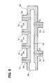
- the connecting portion 56 (corresponding to the connecting portion 31) and the sealing portion 57 (corresponding to the sealing portion 32) are formed in each branched segment 51, as shown in FIG. 8.
- the connecting portion 56 and the sealing portion 57 are formed through, for example, a cutting process.
- the sealing member 60 is formed of, for example, a resin material, a rubber material or a mixture thereof.
- the sealing member 60 is shaped as a hollow cylindrical body, which has a communication passage 61 therein.
- the sealing member 60 includes first to third engaging portions 71-73. The first engaging portion 71 engages the sealing portion 57.
- the second engaging portion 72 engages the connecting portion 56.
- the third engaging portion 73 engages an outer end of the branched segment 51.
- the sealing portion 57 and the connecting portion 56 are separated from a portion of an inner wall 50a of the bar member 50, in which the axial hole 52, the branched holes 53 and the chamfered sections 55 are formed.
- the sealing member 60 is connected to the corresponding branched segment 51 by press fitting the sealing member 60 into the connecting portion 56 or by threadably connecting the sealing member 60 to the connecting portion 56.
- each sealing member 60 is connected to the corresponding branched segment 51 of the bar member 50, the bar member 50 is soaked in plating solution.
- the plating solution flows into the bar member 50 through an opening 58 of the axial hole 52 of the bar member 50 shown in FIG. 6 and also through the communication passage 61 of the sealing member 60.
- a plated part 81 is formed in the inner wall 50a of the bar member 50 except the connecting portions 56 and the sealing portions 57, which are separated from the rest of the inner wall 50a by the corresponding sealing members 60.
- the plating solution does not enter the sealing portion 57 and the connecting portion 56. Furthermore, when the bar member 50 is soaked in the plating solution, the outer wall of the bar member 50 is plated simultaneously with the inner wall 50a of the bar member 50.
- the plating layer of the plated part 81 can be formed, for example, by an electrolytic plating process.
- the plating layer tends to be accumulated in each concaved surface point rather than each convex surface point in the rough surface.
- the surface is effectively smoothed. If metal impurities are present in plating solution used in the electrolytic plating process, the metal impurities tend to be accumulated in the plated surface and make the surface sandy. In order to restrain this, the metal impurities in the plating solution can be removed by, for example, a corresponding device to make the surface smoother.
- the plated part 81 is formed in both the inner wall 50a and the outer wall of the bar member 50, and each unplated part is formed in the corresponding connecting portion 56 and sealing portion 57.
- each sealing member 60 is removed from the bar member 50, so that the accumulator vessel 10 shown in FIGS. 1 to 4 is produced.
- the sealing plug 20 is press fitted into or is threadably connected to the accumulator vessel 10 to form the high pressure fuel supply device 1.
- the plated part 41 is formed in the accumulator vessel 10 of the high pressure fuel supply device 1 of the first embodiment of the present invention after formation of each chamfered section 15.
- a surface of the portion of the inner wall 10a of the accumulator vessel 10, in which the accumulation chamber 13, the fuel passages 14 and the chamfered sections 15 are formed, is smoothed by the plated part 41.
- the surface of the inner wall 10a of the accumulator vessel 10 is smoothed by the plated part 41 as described above, it is not required to provide an additional process, such as an abrasive flow machining process, after formation of the chamfered sections 15. Therefore, the surface of the inner wall 10a is substantially free of residual debris, such as abrasive grains left after the abrasive flow machining process. In addition, residual debris, which has adhered to the inner wall 10a of the accumulator vessel 10 before the formation of the plated part 41, is covered with the plating of the plated part 41. Thus, the amount of residual debris in the accumulator vessel 10 can be reduced.
- the formation of the unplated part 42 in the corresponding connecting portion 31 and the sealing portion 32 can prevent generation of debris, which could be formed upon scratching of plating, and a reduction in the sealing performance of the sealing, so that fuel leakage from the connection between the accumulator vessel 10 and the fuel pipe 2 can be restrained. As a result, reliability of the high pressure fuel supply device 1 can be advantageously improved.
- the formation of the plated part 41 results in the smoothing of the inner wall 10a of the accumulator vessel 10.
- the abrasive flow machining process which requires a relatively long processing time, and a washing process, which is performed after the abrasive flow machining process, are not required.
- the number of manufacturing steps and the total manufacturing time can be advantageously reduced.
- the plated part 43 is formed in the outer wall 10b of the accumulator vessel 10.
- corrosion of the accumulator vessel 10 can be advantageously limited to increase the lifetime of the high pressure fuel supply device 1.
- the formation of the plated part 43 in the outer wall 10b of the accumulator vessel 10 can be simultaneously performed with the formation of the plated part 41 in the inner wall 10b, so that there is no increase in the number of the manufacturing steps or the total manufacturing time.
- a high pressure fuel supply device according to a second embodiment of the present invention will be described.
- the second embodiment differs from the first embodiment in the manufacturing operation of the high pressure fuel supply device.
- the manufactured high pressure fuel supply device of the second embodiment is substantially the same as that of the first embodiment.
- the axial hole 52 which becomes the accumulation chamber 13
- the branched holes 53 which become the fuel passages, are formed in the bar member 50.
- the branched segments 51 which become the fuel inlets 11 and the fuel outlets 12, are formed integrally with the bar member 50.
- each chamfered section 52 is formed in the connection between the axial hole 52 and the corresponding branched hole 53.
- the bar member 50 is soaked in the plating solution. In this way, the plated part 81 is formed in each of the inner wall 50a and the outer wall 50b of the bar member 50, as shown in FIG. 10.
- each connecting portion and each sealing portion are formed in the corresponding branched segment 51.
- the connecting portion and the sealing portion are formed by enlarging an inner diameter of the branched hole 53 of the corresponding branched segment 51.
- the connecting portion and the sealing portion are formed through, for example, a cutting process or machining process.
- a portion of the plated part 81 in each branched hole 53 is removed, so that the connecting portion and the sealing portion become an unplated part, in which no plating is provided.
- each branched segment 51, in which the connecting portion and the sealing portion are formed has a shape that is substantially the same as that of, for example, the fuel outlet of the first embodiment shown in FIG. 2.
- the bar member 50 is washed to remove debris generated through the formation of the connecting portions and the sealing portions.
- the debris generated through the formation of the connecting portions and the sealing portions can be easily removed through a simple washing process, so that a long time washing process is not required.
- the accumulator vessel 10 is produced. Then, the sealing plug 20 is connected to the accumulator vessel 10 by press fitting of the sealing plug 20 into the accumulator vessel 10 or by threadably connecting the sealing plug 20 to the accumulator vessel 10. As a result, the high pressure fuel supply device 1 is produced.
- the plated part 81 is formed in the bar member 50 before formation of the connecting portions and the sealing portions.
- the formation of the connecting portions and the sealing portions in the bar member 50, in which the plated part 81 is formed, allows elimination of the installation process for installing each sealing member 60 to the bar member 50.
- the manufacturing of the accumulator vessel 10 is eased.
- the connecting portions and the sealing portions are formed in the bar member 50 after the formation of the plated part 81, removal of the debris is easy.
- complication and elongation of the manufacturing operation can be advantageously avoided.
- the total manufacturing time of the accumulator vessel 10 can be reduced.
- a chamfered section (15) is formed in a connection between an accumulation chamber (13) and a corresponding fuel passage (14).
- An inner plated part (41), which includes a plating layer, is formed along a wall surface of the accumulation chamber (13), a wall surface of the fuel passage (14) and a wall surface of the chamfered section (15).
- the pressure accumulator vessel (10) further includes connecting portions (31) and sealing portions (32).
- the connecting portion (31) is formed to join with a fuel pipe (2).
- the sealing portion (32) is formed adjacent to the connecting portion (31) to fluid-tightly engage with the fuel pipe (2).
- Each unplated part (42) is formed along a wall surface of the corresponding connecting portion (31) and a wall surface of the corresponding sealing portion (32).
Landscapes
- Engineering & Computer Science (AREA)
- Chemical & Material Sciences (AREA)
- Combustion & Propulsion (AREA)
- Mechanical Engineering (AREA)
- General Engineering & Computer Science (AREA)
- Fuel-Injection Apparatus (AREA)
- Supply Devices, Intensifiers, Converters, And Telemotors (AREA)
Abstract
Description
Claims (10)
- A high pressure fuel supply device having a pressure accumulator vessel (10) that includes:a pressure accumulation chamber (13) that extends in an axial direction of the pressure accumulator vessel (10); anda fuel passage (14) that fluidly communicates between the accumulation chamber (13) and an outside of the pressure accumulator vessel (10), the high pressure fuel supply device being characterized in that the pressure accumulator vessel (10) further includes a chamfered section (15) that is formed in a connection between the accumulation chamber (13) and the fuel passage (14), wherein an inner plated part (41), which includes a plating layer, is formed along a wall surface of the accumulation chamber (13), a wall surface of the fuel passage (14) and a wall surface of the chamfered section (15).
- A high pressure fuel supply device according to claim 1, characterized in that the pressure accumulator vessel (10) further includes:a connecting portion (31) that is formed to join with an external fuel pipe (2) in such a manner that the fuel pipe (2) is securely held by the connecting portion (31) and is fluidly communicated with the fuel passage (14); anda sealing portion (32) that is formed adjacent the connecting portion (31) to fluid-tightly engage with the fuel pipe (2), wherein an unplated part (42) is formed along a wall surface of the connecting portion (31) and a wall surface of the sealing portion (32).
- A high pressure fuel supply device according to claim 1 or 2, characterized in that the pressure accumulator vessel (10) further includes an outer plated part (43) that includes a plating layer and is formed along an outer wall surface (10b) of the accumulator vessel (10).
- A high pressure fuel supply device according to any one of claims 1 to 3, characterized in that the plating layer of each plated part (41, 43) includes a hard chromium plating layer.
- A high pressure fuel supply device according to any one of claims 1 to 4, characterized in that a thickness of the plating layer of each plated part (41, 42) is equal to or greater than 30 µm.
- A manufacturing method of a high pressure fuel supply device (1), to which an external fuel pipe (2) is joined, the method being characterized by:forming an axial hole (52), a branched hole (53) and a chamfered section (55) in a bar member (50), wherein:the axial hole (52) extends in an axial direction of the bar member (50);the branched hole (53) fluidly communicates between the axial hole (52) and an outside of the bar member (50); andthe chamfered section (55) is formed in a connection between the axial hole (52) and the branched hole (53);forming a connecting portion (56) and a sealing portion (57) in the bar member (50), wherein:the connecting portion (56) is formed to join with the external fuel pipe (2) in such a manner that the fuel pipe (2) is securely held by the connecting portion (56) and is fluidly communicated with the branched hole (53); andthe sealing portion (57) is formed adjacent to the connecting portion (56) to fluid-tightly engage with the fuel pipe (2);installing a removable sealing member (60) in the bar member (50) in such a manner that the sealing member (60) engages the connecting portion (56) and the sealing portion (57) to fluid-tightly separate the axial hole (52) and the branched hole (53) from the connecting portion (56) and the sealing portion (57); andforming a plated part (81), which includes a plating layer, along a wall surface of the axial hole (52), a wall surface of the branched hole (53) and a wall surface of the chamfered section (55).
- A manufacturing method according to claim 6, characterized in that the forming of the plated part (81) including forming the plated part (81) along an outer wall surface (50b) of the bar member (50) when the plated part (81) is formed along the wall surface of the axial hole (52), the wall surface of the branched hole (53) and the wall surface of the chamfered section (55).
- A manufacturing method according to claim 7, characterized in that the forming of the plated part (81) including soaking of the bar member (50) in plating solution.
- A manufacturing method of a high pressure fuel supply device (1), to which an external fuel pipe (2) is joined, the method being characterized by:forming an axial hole (52), a branched hole (53) and a chamfered section (55) in a bar member (50), wherein:the axial hole (52) extends in an axial direction of the bar member (50);the branched hole (53) fluidly communicates between the axial hole (52) and an outside of the bar member (50); andthe chamfered section (55) is formed in a connection between the axial hole (52) and the branched hole (53);forming a plated part (81), which includes a plating layer, along a wall surface of the axial hole (52), a wall surface of the branched hole (53) and a wall surface of the chamfered section (55); andforming a connecting portion (56) and a sealing portion (57) in the bar member (50) that includes the plated part (81), wherein:the connecting portion (56) is formed to join with the external fuel pipe (2) in such a manner that the fuel pipe (2) is securely held by the connecting portion (56) and is fluidly communicated with the branched hole (53); andthe sealing portion (57) is formed adjacent to the connecting portion (56) to fluid-tightly engage with the fuel pipe (2).
- A manufacturing method according to claim 9, further characterized by washing the branched hole (53) and the axial hole (52) after the forming of the connecting portion (56) and the sealing portion (57).
Applications Claiming Priority (2)
| Application Number | Priority Date | Filing Date | Title |
|---|---|---|---|
| JP2002103402 | 2002-04-05 | ||
| JP2002103402 | 2002-04-05 |
Publications (2)
| Publication Number | Publication Date |
|---|---|
| EP1350946A2 true EP1350946A2 (en) | 2003-10-08 |
| EP1350946A3 EP1350946A3 (en) | 2005-03-16 |
Family
ID=28035958
Family Applications (1)
| Application Number | Title | Priority Date | Filing Date |
|---|---|---|---|
| EP03007790A Withdrawn EP1350946A3 (en) | 2002-04-05 | 2003-04-04 | High pressure fuel supply device having plating layer and manufacturing method thereof |
Country Status (2)
| Country | Link |
|---|---|
| US (1) | US6789528B2 (en) |
| EP (1) | EP1350946A3 (en) |
Cited By (2)
| Publication number | Priority date | Publication date | Assignee | Title |
|---|---|---|---|---|
| WO2007071481A1 (en) * | 2005-12-19 | 2007-06-28 | Robert Bosch Gmbh | High-pressure connection and method for producing a high-pressure connection |
| US10947624B2 (en) | 2015-11-18 | 2021-03-16 | Sanoh Industrial Co., Ltd. | Fuel distribution pipe |
Families Citing this family (5)
| Publication number | Priority date | Publication date | Assignee | Title |
|---|---|---|---|---|
| DE102007018471A1 (en) * | 2007-04-19 | 2008-10-23 | Robert Bosch Gmbh | Intersection between a high pressure chamber and a high pressure channel |
| SE532352C2 (en) | 2008-04-14 | 2009-12-22 | Sapa Profiler Ab | Sealing method and dressings |
| JP2011052606A (en) * | 2009-09-02 | 2011-03-17 | Otics Corp | Fuel delivery pipe and method for manufacturing the same |
| EP2392816B1 (en) * | 2010-06-03 | 2013-10-09 | Delphi Technologies Holding S.à.r.l. | Stress Relief in Pressurized Fluid Flow System |
| US8622046B2 (en) | 2010-06-25 | 2014-01-07 | Caterpillar Inc. | Fuel system having accumulators and flow limiters |
Family Cites Families (10)
| Publication number | Priority date | Publication date | Assignee | Title |
|---|---|---|---|---|
| US3227147A (en) * | 1959-07-15 | 1966-01-04 | Gossiaux Camille | Shock absorbing tubing for diesel engine fuel injection systems |
| US6045162A (en) * | 1997-01-14 | 2000-04-04 | Usui Kokusai Sangyo Kaisha Limited | Joint head for high-pressure metal piping, and common rail to which the piping is to be joined |
| JP2000007390A (en) | 1998-06-18 | 2000-01-11 | Sekisui Chem Co Ltd | Interlayer for laminated glass |
| JP3888410B2 (en) * | 1998-09-01 | 2007-03-07 | 株式会社デンソー | High pressure fuel supply device |
| US6584959B2 (en) * | 1999-05-27 | 2003-07-01 | Itt Manufacturing Enterprises, Inc. | Thick walled convoluted tubing for use in fuel feed and return applications |
| DE19936535A1 (en) * | 1999-08-03 | 2001-02-15 | Bosch Gmbh Robert | High pressure fuel accumulator |
| DE19949962A1 (en) * | 1999-10-16 | 2001-04-26 | Bosch Gmbh Robert | Fuel high pressure storage for a common-rail fuel injection system of IC engine with hollow basic body which is equipped with several connection openings |
| JP2001280218A (en) | 2000-01-26 | 2001-10-10 | Usui Internatl Ind Co Ltd | Common rail for diesel engine |
| US6494183B2 (en) | 2000-01-26 | 2002-12-17 | Usui Kokusai Sangyo Kaisha Limited | Common rail for diesel engine |
| DE10012961A1 (en) * | 2000-03-16 | 2001-09-20 | Bosch Gmbh Robert | High pressure part for fuel injection system; has intersecting bores, where at least one bore has flat part and part has internal pressure stresses in area of flat part |
-
2003
- 2003-03-19 US US10/390,673 patent/US6789528B2/en not_active Expired - Fee Related
- 2003-04-04 EP EP03007790A patent/EP1350946A3/en not_active Withdrawn
Cited By (2)
| Publication number | Priority date | Publication date | Assignee | Title |
|---|---|---|---|---|
| WO2007071481A1 (en) * | 2005-12-19 | 2007-06-28 | Robert Bosch Gmbh | High-pressure connection and method for producing a high-pressure connection |
| US10947624B2 (en) | 2015-11-18 | 2021-03-16 | Sanoh Industrial Co., Ltd. | Fuel distribution pipe |
Also Published As
| Publication number | Publication date |
|---|---|
| US20030188715A1 (en) | 2003-10-09 |
| EP1350946A3 (en) | 2005-03-16 |
| US6789528B2 (en) | 2004-09-14 |
Similar Documents
| Publication | Publication Date | Title |
|---|---|---|
| US5402829A (en) | Structure for high-pressure fuel injection tube and method of manufacturing the same | |
| US6390720B1 (en) | Method and apparatus for connecting a tube to a machine | |
| US6840283B2 (en) | High-pressure fuel injection pipe having connecting head portion | |
| US6789528B2 (en) | High pressure fuel supply device having plating layer and manufacturing method thereof | |
| KR101076215B1 (en) | Common rail | |
| US20010010216A1 (en) | Common rail for diesel engine | |
| US7726590B2 (en) | Fuel injector director plate having chamfered passages and method for making such a plate | |
| JP2001295723A (en) | Accumulation type fuel injection device | |
| US6206379B1 (en) | Second pressure ring for Al cylinders and its producing method | |
| JP5325306B2 (en) | Fuel injection system | |
| JP2004003455A (en) | High pressure fuel supply device and method of manufacturing the same | |
| KR20190097248A (en) | Environmental resistance member, vanes, compressors and engines using the same | |
| JP2910549B2 (en) | Anti-vibration rubber with bracket | |
| US7195004B2 (en) | Fuel injector cup with improved lead-in dimensions for reduced insertion force | |
| US20180066349A1 (en) | Method for coating a cylinder of an internal combustion engine, and cylinder for an internal combustion engine | |
| JP2000140991A (en) | Connector bolt and its production | |
| CN216742003U (en) | Screw compressor exhaust seat with anti-corrosion function | |
| US6705010B1 (en) | Method and apparatus for reducing the force required to insert a seal in a cavity | |
| US20050280259A1 (en) | Multilayer metallic high pressure conduit | |
| US20050127209A1 (en) | Director plate having smooth exits | |
| CN222789486U (en) | A shock-resistant hydrocyclone separator | |
| CN216974961U (en) | Organism, oil pump, engine and vehicle | |
| KR102741496B1 (en) | Foreign substance suction strainer | |
| US20250367771A1 (en) | Drain shield | |
| JP4054349B2 (en) | Plating method |
Legal Events
| Date | Code | Title | Description |
|---|---|---|---|
| PUAI | Public reference made under article 153(3) epc to a published international application that has entered the european phase |
Free format text: ORIGINAL CODE: 0009012 |
|
| AK | Designated contracting states |
Kind code of ref document: A2 Designated state(s): AT BE BG CH CY CZ DE DK EE ES FI FR GB GR HU IE IT LI LU MC NL PT RO SE SI SK TR |
|
| AX | Request for extension of the european patent |
Extension state: AL LT LV MK |
|
| PUAL | Search report despatched |
Free format text: ORIGINAL CODE: 0009013 |
|
| 17P | Request for examination filed |
Effective date: 20041209 |
|
| AK | Designated contracting states |
Kind code of ref document: A3 Designated state(s): AT BE BG CH CY CZ DE DK EE ES FI FR GB GR HU IE IT LI LU MC NL PT RO SE SI SK TR |
|
| AX | Request for extension of the european patent |
Extension state: AL LT LV MK |
|
| AKX | Designation fees paid |
Designated state(s): DE FR GB |
|
| STAA | Information on the status of an ep patent application or granted ep patent |
Free format text: STATUS: THE APPLICATION IS DEEMED TO BE WITHDRAWN |
|
| 18D | Application deemed to be withdrawn |
Effective date: 20060209 |