EP1350882A2 - Detergent drawer for a washing machine - Google Patents
Detergent drawer for a washing machine Download PDFInfo
- Publication number
- EP1350882A2 EP1350882A2 EP02256375A EP02256375A EP1350882A2 EP 1350882 A2 EP1350882 A2 EP 1350882A2 EP 02256375 A EP02256375 A EP 02256375A EP 02256375 A EP02256375 A EP 02256375A EP 1350882 A2 EP1350882 A2 EP 1350882A2
- Authority
- EP
- European Patent Office
- Prior art keywords
- detergent
- chamber
- partition member
- washing machine
- supply apparatus
- Prior art date
- Legal status (The legal status is an assumption and is not a legal conclusion. Google has not performed a legal analysis and makes no representation as to the accuracy of the status listed.)
- Granted
Links
Images




Classifications
-
- D—TEXTILES; PAPER
- D06—TREATMENT OF TEXTILES OR THE LIKE; LAUNDERING; FLEXIBLE MATERIALS NOT OTHERWISE PROVIDED FOR
- D06F—LAUNDERING, DRYING, IRONING, PRESSING OR FOLDING TEXTILE ARTICLES
- D06F39/00—Details of washing machines not specific to a single type of machines covered by groups D06F9/00 - D06F27/00
- D06F39/02—Devices for adding soap or other washing agents
-
- A—HUMAN NECESSITIES
- A47—FURNITURE; DOMESTIC ARTICLES OR APPLIANCES; COFFEE MILLS; SPICE MILLS; SUCTION CLEANERS IN GENERAL
- A47B—TABLES; DESKS; OFFICE FURNITURE; CABINETS; DRAWERS; GENERAL DETAILS OF FURNITURE
- A47B88/00—Drawers for tables, cabinets or like furniture; Guides for drawers
- A47B88/40—Sliding drawers; Slides or guides therefor
-
- A—HUMAN NECESSITIES
- A47—FURNITURE; DOMESTIC ARTICLES OR APPLIANCES; COFFEE MILLS; SPICE MILLS; SUCTION CLEANERS IN GENERAL
- A47B—TABLES; DESKS; OFFICE FURNITURE; CABINETS; DRAWERS; GENERAL DETAILS OF FURNITURE
- A47B88/00—Drawers for tables, cabinets or like furniture; Guides for drawers
- A47B88/90—Constructional details of drawers
- A47B88/969—Drawers having means for organising or sorting the content
- A47B88/975—Drawers having means for organising or sorting the content in the form of repositionable partition walls
-
- D—TEXTILES; PAPER
- D06—TREATMENT OF TEXTILES OR THE LIKE; LAUNDERING; FLEXIBLE MATERIALS NOT OTHERWISE PROVIDED FOR
- D06F—LAUNDERING, DRYING, IRONING, PRESSING OR FOLDING TEXTILE ARTICLES
- D06F39/00—Details of washing machines not specific to a single type of machines covered by groups D06F9/00 - D06F27/00
- D06F39/12—Casings; Tubs
Definitions
- the present invention relates to a detergent drawer for a washing machine comprising a chamber to receive detergent for washing laundry and a partition to divide the chamber into a primary and secondary detergent chambers.
- the invention also relates to a washing machine incorporating the detergent drawer.
- a known type of washing machine has a cylindrical tub which is mounted for rotation and into which laundry to be washed is placed. Such washing machines are typically classified into drum type washing machines and vertical shaft type washing machines.
- drum type washing machine the rotary tub is mounted for rotation within a housing about a horizontal axis. Rotation of the tub in each direction repeatedly lifts and drops laundry placed in the drum to wash it.
- vertical shaft type washing machine the rotary tub is mounted for rotation within a housing about a vertical axis.
- a pulsator is mounted within the drum and creates water currents in the washing water to clean the laundry placed within it.
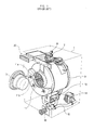
- a known drum type washing machine having a conventional detergent supply apparatus is shown in Figure 1 and includes a housing 1 and a drum 9 suspended in the housing 1.
- a cylindrical tub 11 is mounted for rotation within the drum 9.
- the drum 9 is suspended in the housing 1 by suspension rods (not shown) and shock absorbers (not shown).
- a front wall of the drum 9 and tub 11 is provided with an opening to enable laundry to be placed in, and removed from, the tub 11.
- the cylindrical sidewall 11 a of the tub is perforated to enable washing water to pass between the drum 9 and tub 11.
- Lifters 11b are also positioned on an internal surface of the rotary tub 11 spaced at regular intervals and serve to repeatedly agitate the laundry inside the tub 11.
- a drive motor 12 is mounted in the housing to rotate the tub 11.
- a door 13 is mounted to the front wall of the housing 1 to enable the opening in the rotary tub 11 and drum 9 to be closed.
- a drain pump 14, a drain hose 15 and a filter 16 are mounted in the housing 1, and are used to discharge the water used for washing from the drum 9.
- a cold water supply valve 7 and a hot water supply valve 8 are provided on the housing 1 for connection to corresponding external water supply sources.
- the washing machine also has a conventional detergent supply apparatus 20, which selectively mixes detergent or fabric softener with wash water fed through the cold and hot water supply valves 7 and 8, and then supplies the mixed wash water to the tub 9.
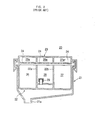
- FIG. 2 A cross-sectional view of a conventional detergent supply apparatus 20 is shown in Figure 2 and comprises a casing 21 defining a box shape, which is open at its front and top.
- a detergent/fabric softener drawer 22 is mounted in the casing 21 beneath a water supply cover 23 through which water is supplied into the casing 21 from the cold and hot water supply valves 7 and 8 (see Figure 1).
- the base of the casing 21 is inclined to form a funnel shape which leads into a wash water outlet 21a so that wash water mixed with the detergent or the fabric softener is fed through the outlet 21a into the tub 9.
- the detergent/fabric softener drawer 22 is slidably mounted in the casing 21 so that the detergent/fabric softener may be placed therein when the drawer 22 is slid forward and out of the casing 21.
- the detergent/fabric softener drawer 22 is partitioned into a secondary detergent storing chamber 26, a main or primary detergent storing chamber 27, and a fabric softener storing chamber 28 by two partition walls 22a and 22b. Detergent for preliminary washing is placed in chamber 26, while the detergent for main wash is placed in chamber 27. Fabric softener is placed in chamber 28 and is mixed with the water used to rinse the laundry after washing.
- the rear face of the detergent/fabric softener drawer 22 is open and is spaced from the rear wall of the casing 21, so that the wash water passes through the drawer 22 and out through outlet 21a of the casing 21 from the storing chambers 26, 27, and 28 of the detergent/fabric softener drawer 22.
- a siphon 29 is mounted to a bottom wall of the fabric softener storing chamber 28, so as to rapidly drain the wash water mixed with the fabric softener.
- the water supply cover 23 extends over the top of the casing 21 and is spaced from the detergent/fabric softener drawer 22 by a predetermined distance.
- the water supply cover 23 is provided with water supply chambers 26a, 27a, and 28a which correspond to the storing chambers 26, 27 and 28, respectively.
- a plurality of drain holes 24 are formed on a bottom wall of each of the water supply chambers 26a, 27a, and 28a, to supply the wash water contained in the water supply chambers 26a, 27a, and 28a to the storing chambers 26, 27, and 28.
- the conventional detergent supply apparatus 20 is designed with two fixed partition walls 22a and 22b that are integrally formed in the detergent/fabric softener drawer 22 to provide the storing chambers 26, 27 and 28.
- the fabric softener storing chamber 28 is positioned between the secondary detergent storing chamber 26 and the main detergent storing chamber 27. Accordingly, the capacity of the secondary detergent storing chamber 26 and the main detergent storing chamber 27 is fixed.
- the user adds additional detergent during operation of the washing machine, or repeats the washing operation several times.
- additional detergent during operation of the washing machine, or repeats the washing operation several times.
- this requires the use of additional wash water, and takes much longer to wash the laundry.
- Adding detergent to the washing water during operation of the machine is also not always possible or feasible.
- the overall size of the secondary and main detergent storing chambers 26 and 27 may be enlarged to accommodate sufficient quantities of detergent, the overall size of the detergent supply apparatus 20 is thus also increased, resulting in an increase in the scale of the washing machine and an increase in manufacturing costs.
- the secondary detergent storing chamber 26 may be omitted so that the size of the main detergent storing chamber 27 may be increased without increasing the overall size of the detergent supply apparatus 20.
- preliminary washing as well as main washing cannot be carried out with a single operation of the washing machine so detergent must be added to the washing machine twice, once for the preliminary wash and once for the main wash. This makes it inconvenient for a user to wash the laundry.
- the present invention overcomes or substantially alleviates the problems described in more detail above.
- a detergent drawer according to the present invention is characterised in that the partition is removable from the chamber.
- the partition is positionable in the chamber to enable infinite adjustment of the capacity of the primary and secondary detergent chambers with respect to each other.
- the partition extends between a pair of opposed parallel walls forming the chamber, the partition being a sliding fit between said walls to retain the partition in position in the chamber when inserted therein.
- the partition comprises a U-shaped channel member which forms the secondary detergent chamber when inserted in the chamber.
- a detergent draw of the present invention can be applied to both drum type washing machines and vertical shaft type washing machines.
- a drum type washing machine having the detergent draw according to the present invention is described below.
- the drum type washing machine has the same structure as that of the conventional drum type washing machine shown in Figure 1 except for the construction of the detergent drawer, so the common elements of this invention will be described herein with reference to Figure 1.
- Figures 3 and 4 show a first embodiment of the present invention.
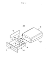
- Figure 3 shows a perspective view of a detergent supply apparatus 30 having a detergent drawer 32 slidably received in a casing 31, with a detachable partition member 42 removed from the drawer 32.
- Figure 4 shows a sectional view of the detergent drawer 32 and casing 31, with the detachable partition member 42 located in the drawer 32.
- the apparatus 30 further includes a water supply cover 33.
- the water supply cover 33 is placed on the top portion of the casing 31, and connected, at its rear wall, to the cold and hot water supply valves 7 and 8 (see Figure 1).
- the drawer 32 is open at its upper and rear portions so that detergent or a fabric softener can be placed therein, and wash water mixed with the detergent or the fabric softener is discharged from the casing 31 through the open rear portion. To smoothly carry out such an operation, the rear end of the drawer 32 is spaced apart from a rear wall of the casing 31.
- the casing 31 is inclined at its bottom to form a funnel shape.
- a wash water outlet 31a is formed at a predetermined position on the bottom of the casing 31, to feed the wash water mixed with the detergent or the fabric softener to the water tub 9 (see Figure 1).
- Water supply chambers 36a, 37a, and 38a are provided in the water supply cover 33 to supply the wash water to the drawer 32. Furthermore, drain holes 34 are formed on a bottom of each of the water supply chambers 36a, 37a, and 38a to supply the wash water to corresponding areas of the drawer 32.
- the drawer 32 comprises a fixed partition member 41 and a detachable partition member 42.
- the fixed partition member 41 is vertically mounted in the detergent/fabric softener container 32, and partitions the drawer 32 into a detergent chamber 35 and a fabric softener chamber 38.
- the detergent chamber 35 is divided into two storing sections.
- the fabric softener chamber 38 Since the fixed partition member 41 is integrated with the detergent/fabric softener container 32, the fabric softener chamber 38 has a fixed capacity. The fabric softener chamber 38 supplies the fabric softener to the wash water in a rinsing operation of a main washing operation.
- the detachable partition member 42 is removably mounted in the detergent chamber 35 to selectively partition the detergent chamber 35 into a primary detergent chamber 37 and a secondary detergent chamber 36 or unite the two sections into one detergent chamber 35.
- the detachable partition member 42 has a plate shape of a predetermined thickness, and is vertically set in the drawer 32.
- the drawer 32 is made of a flexible material, for example, a plastic.
- a support member 40 links both side ends of the open rear portion of the detergent chamber 35 to each other, and is used to reinforce the detergent chamber 35 having a relatively long length, as well as to support a rear end of the detachable partition member 42.
- the support member 40 is placed at a position which is distant from a bottom wall of the detergent chamber 35 by a predetermined height, so as to have the wash water flow into the detergent chamber 35, mixed with the detergent, and be discharged from the casing 31.
- the drawer 32 and the support member 40 may slightly bulge outward. That is, where the detachable partition member 42 is fitted between a front wall of the drawer 32 and the support member 42, a front end of the detachable partition member 42 is in contact with an inner surface of the front wall of the drawer 32, while the rear end of the detachable partition member 42 is in contact with an inner surface of the support member 40. By upwardly pulling the detachable partition member 42, the detachable partition member 42 is easily removed from the drawer 32.
- the detergent chamber 35 is partitioned into a secondary detergent storing chamber 36 and a primary detergent storing chamber 37.
- the secondary detergent storing chamber 36 is placed at a position corresponding to the water supply chamber 36a while the primary detergent storing chamber 37 is placed at a position corresponding to the water supply chambers 37a.
- the detergent can be separately supplied to the secondary detergent storing chamber 36 and the main detergent storing chamber 37.
- the washing machine is capable of performing the main washing operation using the wash water passed through the main detergent storing chamber 37, after performing a preliminary washing operation using the wash water passed through the secondary detergent storing chamber 36.
- the washing machine having the detergent supply apparatus of the present invention is operated in the same manner as a conventional washing machine which washes laundry twice, in the case of washing excessively dirty or oily laundry.
- detergent capacities of the corresponding washing operations can be changeably set by the user according to the position of the detachable partition member 42.
- the detergent chamber 35 can be used as a sole detergent chamber.
- the capacity of the main detergent storing chamber 37 is increased to contain a large quantity of detergent therein. Therefore, in the case of washing laundry in an area where a quality of water is poor, or where a user desires to increase the detergent in the washing machine, the user may remove the detachable partition member 42 from the detergent chamber 35.
- the user To remove the detachable partition member 42 from the detergent chamber 35, the user simply lifts up the detachable partition member 42, as shown in Figure 3.
- the detachable partition member 42 may be designed to lie down on the bottom wall of the drawer 32 as necessary, as shown by the two-dot chain line of Figure 4. Such a construction allows the detachable partition member 42 to be easily kept in the drawer 32 without degrading its original function.
- the washing machine may sequentially perform the preliminary washing operation and the main washing operation.
- the detachable partition member 42 is installed in the detergent chamber 35 to partition the chamber 35 into the secondary detergent storing chamber 36 and the primary detergent storing section 37 (See Figure 4).
- a user may take out the drawer 32 from the casing 31 by pulling it forward from the casing 31.
- the user places adequate quantities of detergent in both the secondary detergent storing chamber 36 and the primary detergent storing section 37 while placing an adequate quantity of the fabric softener in the fabric softener chamber 38. Thereafter, the pushes the drawer 32 back into the casing 31.
- wash water flows into the water supply chamber 36a from the cold water supply valve 7 or the hot water supply valve 8 (see Figure 1), and drops into the secondary detergent storing chamber 36 through the drain holes 34.
- the wash water is mixed with the detergent contained in the secondary detergent storing chamber 36, and then supplied to the water tub 9 through the wash water outlet 31a of the casing 31 (see Figure 1).
- the washing machine sequentially performs a washing operation, a rinsing operation, and a draining operation of the preliminary washing operation.
- the washing machine is programmed not to use the fabric softener in the rinsing operation of the preliminary washing operation.
- the main washing operation is carried out.
- the wash water flows into the water supply chamber 37a, and drops into the primary detergent storing chamber 37 through the drain holes 34.
- the wash water is mixed with the detergent in the main detergent storing chamber 37, and then supplied to the water tub 9 through the wash water outlet 31a of the casing 31.
- the washing machine sequentially performs a washing operation, a rinsing operation, and a draining operation in the same manner as the preliminary washing operation, thus finishing the sequential washing operation.
- the wash water flows into the fabric softener chamber 38 through the water supply chamber 38a and the drain holes 34, and is mixed with the fabric softener.
- the wash water with the fabric softener is fed to the water tub 9 by using a siphon 39 and the wash water outlet 31a of the casing 31 (see Figure 4).
- the user may remove the detachable partition member 42 from the detergent chamber 35 as shown in Figure 3.
- the user may lay the detachable partition member 42 on the bottom wall of the detergent chamber 35, as shown by the two-dot chain line of Figure 4, to use the detergent chamber 35 as the main detergent storing chamber.
- the washing machine After placing the detergent in the chamber 35 having an increased interior capacity and adding the fabric softener in the fabric softener chamber 38, the washing machine is operated. At this time, wash water flows into the detergent chamber 35 through the water supply chamber 37a and the drain holes 34, and is mixed with the detergent. Next, the wash water flows into the water tub 9 through the wash water outlet 31a of the casing 31.
- a rotary tub 11 (see Figure 1) is rotated to wash the laundry.
- the wash water flows into the fabric softener chamber 38 through the water supply chamber 38a, and the wash water mixed with the fabric softener is fed to the water tub 9 to rinse the laundry.
- the washing machine performs a draining operation to finish the single washing operation to wash the laundry.
- the detergent chamber 35 can contain a large quantity of detergent.
- the washing machine where the quality of water is poor, or where a user desires to place a large quantity of detergent in the washing machine.
- Figures 5 and 6 show a detergent supply apparatus according to another embodiment of the present invention.
- Figure 5 shows a perspective view of the detergent supply apparatus 30A, with a detachable partition member 42 removed from the detergent supply apparatus 30A.
- Figure 6 shows a sectional view of the detergent supply apparatus 30A with the detachable partition member 42 set in the detergent supply apparatus 30A.
- Each of the holding units 43 is placed at a junction between the water supply chamber 36a and the water supply chamber 37a of the water supply cover 33.
- Each of the holding units 43 includes two projecting ribs or lugs 43a spaced from each other to form a gap 43b.
- the two projecting ribs 43a are spaced apart from each other by a thickness of the detachable partition member 42 to form the gap 43b.
- an end of the detachable partition member 42 is fitted into each of the gaps 43b to be held by the projecting ribs 43a.
- the detachable partition member 42 is stably set in the detergent chamber 35.
- the user may simply lift up the detachable partition member 42. At this time, the detachable partition member 42 is easily removed from the detergent chamber 35.
- the holding units 43 are provided on the front and rear ends of the detergent chamber 35. However, it is understood that they may be provided at other desired locations, and one or more additional holding units may be provided.
- Figures 7 and 8 show a detergent supply apparatus according to yet another embodiment of the present invention.
- Figure 7 shows a perspective view of the detergent supply apparatus 30B, with a detachable partition member 52 removed from the detergent supply apparatus 30B.
- Figure 8 shows a sectional view of the detergent supply apparatus 30B, with the detachable partition member 52 mounted in the detergent supply apparatus 30B.
- the detachable partition member 52 includes two sidewalls 52a and 52b and a bottom wall 52c to have a channel-shape.
- a left-hand sidewall 52a of the detachable partition member 52 comes into contact with a left-hand sidewall of the detergent chamber 35, as shown in Figure 8, and the detergent chamber 35 is easily partitioned into the secondary detergent storing chamber 36 and the main detergent storing chamber 37.
- the detachable partition member 52 itself forms the secondary detergent storing chamber 36 to store the detergent.
- the bottom wall 52c of the detachable partition member 52 is equal to or slightly wider than the water supply chamber 36a in its width.
- a holding protrusion 53 may be formed on the bottom wall of the detergent chamber 35 so as to be upwardly protruded from the bottom wall of the detergent chamber 35 by a predetermined length. Where the detachable partition member 52 is set in the detergent chamber 35, a right-hand sidewall 52b of the detachable partition member 52 is held by the holding protrusion 53.
- the present invention provides a detergent supply apparatus having a detachable partition member which is removably set in a detergent chamber, so as to partition the detergent chamber into a secondary detergent storing section and a main detergent storing section in response to the detachable partition member being set in the detergent chamber. Otherwise, the detergent chamber is entirely used as the main detergent storing section in response to the detachable partition member being removed from the detergent chamber.
- the operator may simply remove the detachable partition member from the detergent chamber to increase the interior capacity of the main detergent storing section.
- the operator may set the detachable partition member in the detergent chamber to allow a separate detergent reservoir in the washing machine to perform main and preliminary washing operations.
Landscapes
- Engineering & Computer Science (AREA)
- Textile Engineering (AREA)
- Detail Structures Of Washing Machines And Dryers (AREA)
Abstract
Description
Therefore, in the case of washing laundry in an area where a quality of water is poor, or where a user desires to increase the detergent in the washing machine, the user may remove the
Claims (34)
- A detergent drawer for a washing machine comprising a chamber (35) to receive detergent for washing laundry and a partition (42, 52) to divide the chamber (35) into primary and secondary detergent chambers (37, 38), characterised in that the partition (42, 52) is removable from the chamber (35).
- A detergent drawer according to claim 1, wherein the partition (42, 52) is positionable in the chamber (35) to enable infinite adjustment of the relative capacity of the primary and secondary detergent chambers (37, 36) with respect to each other.
- A detergent drawer according to claim 2, wherein the partition (42, 52) extends between a pair of opposed parallel walls forming the chamber (35), the partition (42, 52) being a sliding fit between said walls to retain the partition (42, 52) in position in the chamber (35) when inserted therein.
- A detergent drawer according to claim 3, wherein the partition (42, 52) comprises a planar sheet of material.
- A detergent drawer according to claim 4, wherein at least one pair of spaced support lugs (43a, 43b) upstand from the base of the chamber (35) to support the partition (42, 52), the partition (42, 52) being received between said pair of lugs (43a, 43b).
- A detergent drawer according to claim 1, wherein the partition (42, 52) comprises a U-shaped channel chamber which forms the secondary detergent chamber (36) when inserted in the chamber (35).
- A detergent drawer according to claim 6, wherein a protruberance (53) upstands from the base of the chamber (35), the partition (42, 52) being supported in the chamber (35) between the protruberance (53) and a side wall of the chamber (35).
- A washing machine incorporating a detergent drawer according to any preceding claim.
- A washing machine comprising:a housing which defines an outer appearance of the washing machine;a tub provided in the housing to receive laundry therein; anda detergent supply apparatus, wherein the detergent supply apparatus comprises:a casing which defines an outer appearance of the detergent supply apparatus,a detergent/fabric softener container slidably set in the casing,a fixed partition member which partitions the detergent/fabric softener container into a detergent chamber and a fabric softener chamber, anda detachable partition member detachably mounted in the detergent chamber so as to partition the detergent chamber to include a secondary detergent storing section and a main detergent storing section, wherein the detergent chamber is used as the main detergent storing section in response to removal of the detachable partition member from the detergent chamber.
- The washing machine according to claim 9, wherein:the detergent/fabric softener container is made of a flexible material, andthe detachable partition member has a plate shape of a predetermined thickness, and is detachably and vertically set in the detergent chamber of the detergent/fabric softener container.
- The washing machine according to claim 10, wherein the detergent supply apparatus further comprises a horizontal support member which is provided at a rear portion of the detergent chamber, and supports a rear end of the detachable partition member.
- The washing machine according to claim 9, wherein:the detergent supply apparatus further comprises a holding unit which is provided on an interior bottom surface of the detergent chamber and removably holds the detachable partition member, andthe detachable partition member has a plate shape of a predetermined thickness, and is fitted into the holding unit to be set in the detergent chamber.
- The washing machine according to claim 12, wherein the holding unit is provided on each of front and rear ends of the interior bottom surface of the detergent chamber.
- The washing machine according to claim 13, wherein:each of the holding units comprises two projecting ribs spaced apart from each other at a regular interval to form a holding slit, andthe detachable partition member is detachably inserted and held in the holding slit.
- The washing machine according to claim 9, wherein the detachable partition member comprises two sidewalls having a distance therebetween, and a bottom wall which connects the two sidewalls and is detachably seated on an interior bottom surface of the detergent chamber.
- The washing machine according to claim 15, wherein the detergent chamber includes a holding protrusion which removably holds the detachable partition member, and is formed at a position spaced from a sidewall of the detergent chamber by a width of the detachable partition member.
- The washing machine according to claim 15, wherein an inner channel area of the detachable partition member forms a section used as the secondary detergent storing section.
- The washing machine according to claim 15, wherein the detergent supply apparatus further comprises a water supply cover which forms a top portion of the casing, and includes water supply chambers having drain holes which supply wash water to corresponding areas of the detergent/fabric softener container.
- The washing machine according to claim 18, wherein:the water supply chambers include first, second and third water supply chambers corresponding to the secondary detergent storing chamber, the main detergent storing chamber and the fabric softener chamber, andthe inner channel area of detachable partition member has a width equal to or greater than that of the first water supply chamber.
- The washing machine according to claim 9, wherein the secondary detergent storing section has a selectable detergent capacity according to placement of the detachable partition member in the detergent chamber.
- The washing machine according to claim 9, wherein the detergent supply apparatus further comprises a water supply cover which forms a top portion of the casing, and includes water supply chambers having drain holes which supply wash water to corresponding areas of the detergent/fabric softener container.
- A washing machine comprising:a housing which defines an outer appearance of the washing machine;a tub provided in the housing to receive laundry therein; anda detergent supply apparatus, wherein the detergent supply apparatus comprises:a casing which defines an outer appearance of the detergent supply apparatus,a detergent/fabric softener container slidably set in the casing,a fixed partition member which partitions the detergent/fabric softener container into a detergent chamber and a fabric softener chamber, andan adjustable partition member arranged in the detergent chamber which partitions the detergent chamber to include a secondary detergent storing section and a main detergent storing section, and otherwise provides the detergent chamber as the main detergent storing section.
- The washing machine according to claim 22, wherein the adjustable partition member has an edge pivotally secured in the detergent chamber, allows the detergent chamber to include the secondary and main detergent storing sections in response to being vertically set in the detergent chamber, and provides the detergent chamber as the main detergent storing section in response to being folded down.
- The washing machine according to claim 23, wherein the detergent supply apparatus further comprises a locking unit provided in the detergent chamber which removably holds the vertically set adjustable partition member.
- The washing machine according to claim 22, wherein the adjustable partition member has a plate shape of predetermined thickness, and is vertically and slidably arranged in the detergent chamber.
- The washing machine according to claim 25, wherein the adjustable partition member allows the detergent chamber to include the secondary and main detergent storing sections in response to being slid in between two sidewalls of the detergent chamber, and provides the detergent chamber as the main detergent storing section in response to being slid to contact either of the two sidewalls of the detergent chamber.
- A detergent supply apparatus which supplies detergent to a washing machine, comprising:a casing which defines an outer appearance of the detergent supply apparatus;a detergent/fabric softener container slidably set in the casing;a fixed partition member which partitions the detergent/fabric softener container into a detergent chamber and a fabric softener chamber; anda detachable partition member detachably mounted in the detergent chamber so as to partition the detergent chamber to include a secondary detergent storing section and a main detergent storing section, wherein the detergent chamber is used as the main detergent storing section in response to removal of the detachable partition member from the detergent chamber.
- The detergent supply apparatus according to claim 27, wherein:the detergent supply apparatus further comprises a holding unit which is provided on an interior bottom surface of the detergent chamber and removably holds the detachable partition member, andthe detachable partition member has a plate shape of a predetermined thickness, and is fitted into the holding unit to be set in the detergent chamber.
- The detergent supply apparatus according to claim 27, wherein the detachable partition member comprises two sidewalls having a distance therebetween, and a bottom wall which connects the two sidewalls and is detachably seated on an interior bottom surface of the detergent chamber.
- The detergent supply apparatus according to claim 29, wherein the detergent chamber includes a holding protrusion which removably holds the detachable partition member, and is formed at a position spaced from a sidewall of the detergent chamber by a width of the detachable partition member.
- A detergent supply apparatus which supplies detergent to a washing machine, comprising:a casing which defines an outer appearance of the detergent supply apparatus;a detergent/fabric softener container slidably set in the casing;a fixed partition member which partitions the detergent/fabric softener container into a detergent chamber and a fabric softener chamber; andan adjustable partition member arranged in the detergent chamber which partitions the detergent chamber to include a secondary detergent storing section and a main detergent storing section, and otherwise provides the detergent chamber as the main detergent storing section.
- The detergent supply apparatus according to claim 31, wherein the adjustable partition member has an edge pivotally secured in the detergent chamber, allows the detergent chamber to include the secondary and main detergent storing sections in response to being vertically set in the detergent chamber, and provides the detergent chamber as the main detergent storing section in response to being folded down.
- The detergent supply apparatus according to claim 31, wherein the adjustable partition member has a plate shape of predetermined thickness, and is vertically and slidably arranged in the detergent chamber.
- The washing machine according to claim 33, wherein the adjustable partition member allows the detergent chamber to include the secondary and main detergent storing sections in response to being slid in between two sidewalls of the detergent chamber, and provides the detergent chamber as the main detergent storing section in response to being slid to contact either of the two sidewalls of the detergent chamber.
Applications Claiming Priority (2)
| Application Number | Priority Date | Filing Date | Title |
|---|---|---|---|
| KR10-2002-0013840A KR100460586B1 (en) | 2002-03-14 | 2002-03-14 | Washing Machine Having Detergent Supply Apparatus |
| KR2002013840 | 2002-03-14 |
Publications (3)
| Publication Number | Publication Date |
|---|---|
| EP1350882A2 true EP1350882A2 (en) | 2003-10-08 |
| EP1350882A3 EP1350882A3 (en) | 2004-01-28 |
| EP1350882B1 EP1350882B1 (en) | 2006-07-12 |
Family
ID=36776476
Family Applications (1)
| Application Number | Title | Priority Date | Filing Date |
|---|---|---|---|
| EP02256375A Expired - Lifetime EP1350882B1 (en) | 2002-03-14 | 2002-09-13 | Detergent drawer for a washing machine |
Country Status (4)
| Country | Link |
|---|---|
| US (1) | US7093467B2 (en) |
| EP (1) | EP1350882B1 (en) |
| KR (1) | KR100460586B1 (en) |
| DE (1) | DE60213061T2 (en) |
Cited By (5)
| Publication number | Priority date | Publication date | Assignee | Title |
|---|---|---|---|---|
| WO2007077146A1 (en) * | 2005-12-30 | 2007-07-12 | Arcelik Anonim Sirketi | A washing machine |
| ES2301316A1 (en) * | 2005-11-25 | 2008-06-16 | Bsh Electrodomesticos España, S.A. | Detergent distributor, has plastic puller with one hand inside and tray distributor detergent removable glass that is assembled with puller, which has front side compared to inner side, rear side opposite to front side and top side |
| EP2325376A1 (en) * | 2009-11-24 | 2011-05-25 | Samsung Electronics Co., Ltd. | Detergent supply apparatus and washing machine having the same |
| WO2010128726A3 (en) * | 2009-05-04 | 2011-08-25 | Lg Electronics Inc. | Washing machine |
| WO2012085843A3 (en) * | 2010-12-21 | 2012-09-13 | Indesit Company S.P.A. | Electrical household appliance with a rotatable panel |
Families Citing this family (33)
| Publication number | Priority date | Publication date | Assignee | Title |
|---|---|---|---|---|
| KR100484830B1 (en) * | 2002-11-28 | 2005-04-22 | 엘지전자 주식회사 | Drum washing machine |
| KR101013375B1 (en) | 2003-11-10 | 2011-02-14 | 삼성전자주식회사 | Drum washing machine |
| KR101064702B1 (en) * | 2004-02-06 | 2011-09-14 | 엘지전자 주식회사 | Detergent Supply Device of Washing Machine |
| US20050183469A1 (en) * | 2004-02-25 | 2005-08-25 | Kang Dong W. | Control panel assembly for washing machine |
| DE602004016725D1 (en) * | 2004-02-27 | 2008-11-06 | Whirlpool Co | Detergent dispenser for a washing machine |
| KR101082561B1 (en) * | 2004-04-14 | 2011-11-10 | 엘지전자 주식회사 | Detergent providing apparatus of washer |
| KR20050118895A (en) * | 2004-06-15 | 2005-12-20 | 삼성전자주식회사 | Washing machine having a detergent feeding device |
| US20060137716A1 (en) * | 2004-11-24 | 2006-06-29 | Gault Gregory E | Water treatment device for an article washer |
| KR101099353B1 (en) * | 2005-01-25 | 2011-12-26 | 엘지전자 주식회사 | Detergent box assembly of drum type washer |
| US20070056330A1 (en) * | 2005-06-29 | 2007-03-15 | Lg Electronics Inc. | Detergent supplying apparatus of washing machine |
| KR101203554B1 (en) * | 2005-06-29 | 2012-11-21 | 엘지전자 주식회사 | Detergent applying apparatus of cleaning device |
| US20070044517A1 (en) * | 2005-08-30 | 2007-03-01 | Samsung Electronics Co., Ltd. | Detergent supplying apparatus of clothes washing machine |
| KR101233188B1 (en) * | 2005-10-12 | 2013-02-15 | 엘지전자 주식회사 | Detergent box of washing machine |
| KR101481508B1 (en) * | 2007-06-13 | 2015-01-13 | 엘지전자 주식회사 | Washing device and control method thereof |
| US7895864B2 (en) * | 2007-10-23 | 2011-03-01 | Electrolux Home Products, Inc. | Laundry additive dispenser |
| US9085844B2 (en) * | 2007-11-13 | 2015-07-21 | Electrolux Home Products, Inc. | Sequenced water delivery in an additive dispenser |
| US8327672B2 (en) * | 2007-12-21 | 2012-12-11 | Electrolux Home Products, Inc. | Methods and systems for water delivery in an additive dispenser |
| US8317236B2 (en) * | 2008-04-16 | 2012-11-27 | Electrolux Home Products, Inc. | Appliance drawer and latch mechanism therefor |
| USD616161S1 (en) * | 2008-05-28 | 2010-05-18 | Electrolux Home Products Corporation, N.V. | Drawer assembly for an appliance |
| US8348361B2 (en) * | 2008-06-30 | 2013-01-08 | Electrolux Home Products, Inc. | Additive dispenser drawer assembly |
| US8931667B2 (en) * | 2008-09-24 | 2015-01-13 | The Procter & Gamble Company | Methods and apparatuses for dispensing fluids |
| US20100161143A1 (en) * | 2008-12-18 | 2010-06-24 | Christopher Lawrence Smith | Dispensing system |
| US8485000B2 (en) * | 2009-07-31 | 2013-07-16 | Lg Electronics Inc. | Clothes treating apparatus with liquid reservoir |
| USD663497S1 (en) * | 2010-05-13 | 2012-07-10 | Lg Electronics Inc. | Laundry detergent holder |
| USD637371S1 (en) * | 2010-08-05 | 2011-05-03 | Samsung Electronics Co., Ltd. | Detergent box for drum washing machine |
| PL2794977T3 (en) * | 2011-12-21 | 2016-08-31 | Bsh Hausgeraete Gmbh | Rinsing arrangement for a domestic appliance for the care of laundry items, and domestic appliance for the care of laundry items |
| JP1463557S (en) * | 2012-02-24 | 2016-02-22 | ||
| US20160215433A1 (en) * | 2015-01-28 | 2016-07-28 | General Electric Company | Unitary top panel for a washing machine appliance |
| KR102466659B1 (en) * | 2015-10-07 | 2022-11-11 | 엘지전자 주식회사 | Laundry treating apparatus |
| US11162208B2 (en) | 2017-07-04 | 2021-11-02 | Lg Electronics Inc. | Clothes processing apparatus and control method therefor |
| CN107385797B (en) * | 2017-07-31 | 2019-10-25 | 无锡小天鹅电器有限公司 | The dissolution case assembly of washing machine and the washing machine with it |
| US11421368B2 (en) | 2020-01-24 | 2022-08-23 | Midea Group Co., Ltd. | Dispenser for a laundry washing machine |
| US12043942B2 (en) | 2020-01-24 | 2024-07-23 | Midea Group Co., Ltd. | Dispenser for a laundry washing machine with overflow configuration |
Family Cites Families (12)
| Publication number | Priority date | Publication date | Assignee | Title |
|---|---|---|---|---|
| US3975931A (en) | 1972-10-26 | 1976-08-24 | Siemens Electrogerate Gmbh | Flush-in device for an appliance such as a laundry or dishwashing machine |
| DE3607632A1 (en) | 1986-03-07 | 1987-09-17 | Bosch Siemens Hausgeraete | Washing machine with a washing-agent flush-in tray |
| DE3618275A1 (en) | 1986-05-30 | 1987-12-03 | Bauknecht Hausgeraete | DETERGENT DISCHARGE TANK |
| DE3715832A1 (en) | 1987-05-12 | 1988-11-24 | Bosch Siemens Hausgeraete | DETERGENT DISCHARGE TRAY WITH AUXILIARY DEVICE FOR LIQUID DETERGENT |
| JPH0798116B2 (en) * | 1988-03-14 | 1995-10-25 | 株式会社東芝 | Dehydrating and washing machine processing agent injection device |
| KR920002670Y1 (en) * | 1989-04-19 | 1992-04-27 | 김종헌 | A dismountable chair |
| KR0124323Y1 (en) * | 1995-03-23 | 1999-05-01 | 김광호 | Detergent input device of washing machine |
| KR100237703B1 (en) * | 1997-12-19 | 2000-01-15 | 윤종용 | Drum washing machine |
| CN1145726C (en) | 1998-06-30 | 2004-04-14 | 大宇电子有限公司 | Drum type washing machine having pump integrally formed with filter |
| KR100301832B1 (en) * | 1998-08-19 | 2001-09-06 | 구자홍 | detergent feeding device in drum-type washing machine |
| DE10065337A1 (en) * | 2000-12-27 | 2002-07-04 | Bsh Bosch Siemens Hausgeraete | Household machine for washing or drying laundry |
| DE60323931D1 (en) * | 2003-02-19 | 2008-11-20 | Whirlpool Co | Washing machine with detergent dispenser |
-
2002
- 2002-03-14 KR KR10-2002-0013840A patent/KR100460586B1/en not_active Expired - Fee Related
- 2002-08-21 US US10/224,555 patent/US7093467B2/en not_active Expired - Lifetime
- 2002-09-13 DE DE60213061T patent/DE60213061T2/en not_active Expired - Lifetime
- 2002-09-13 EP EP02256375A patent/EP1350882B1/en not_active Expired - Lifetime
Cited By (8)
| Publication number | Priority date | Publication date | Assignee | Title |
|---|---|---|---|---|
| ES2301316A1 (en) * | 2005-11-25 | 2008-06-16 | Bsh Electrodomesticos España, S.A. | Detergent distributor, has plastic puller with one hand inside and tray distributor detergent removable glass that is assembled with puller, which has front side compared to inner side, rear side opposite to front side and top side |
| ES2301316B1 (en) * | 2005-11-25 | 2009-07-20 | Bsh Electrodomesticos España, S.A. | DETERGENT DISTRIBUTOR. |
| WO2007077146A1 (en) * | 2005-12-30 | 2007-07-12 | Arcelik Anonim Sirketi | A washing machine |
| WO2010128726A3 (en) * | 2009-05-04 | 2011-08-25 | Lg Electronics Inc. | Washing machine |
| EP2325376A1 (en) * | 2009-11-24 | 2011-05-25 | Samsung Electronics Co., Ltd. | Detergent supply apparatus and washing machine having the same |
| US8826700B2 (en) | 2009-11-24 | 2014-09-09 | Samsung Electronics Co., Ltd. | Detergent supply apparatus and washing machine having the same |
| US9340919B2 (en) | 2009-11-24 | 2016-05-17 | Samsung Electronics Co., Ltd. | Detergent supply apparatus and washing machine having the same |
| WO2012085843A3 (en) * | 2010-12-21 | 2012-09-13 | Indesit Company S.P.A. | Electrical household appliance with a rotatable panel |
Also Published As
| Publication number | Publication date |
|---|---|
| KR20030074858A (en) | 2003-09-22 |
| DE60213061T2 (en) | 2007-01-11 |
| US20030172690A1 (en) | 2003-09-18 |
| DE60213061D1 (en) | 2006-08-24 |
| EP1350882B1 (en) | 2006-07-12 |
| EP1350882A3 (en) | 2004-01-28 |
| KR100460586B1 (en) | 2004-12-09 |
| US7093467B2 (en) | 2006-08-22 |
Similar Documents
| Publication | Publication Date | Title |
|---|---|---|
| EP1350882A2 (en) | Detergent drawer for a washing machine | |
| US6826933B2 (en) | Dual use detergent dispenser | |
| EP1463854B1 (en) | Apparatus for supplying detergent in washer | |
| RU2324025C2 (en) | Laundry washer | |
| US7428831B2 (en) | Detergent container of washing machine | |
| EP2325376B1 (en) | Detergent supply apparatus and washing machine having the same | |
| US20050241347A1 (en) | Detergent supply apparatus of washing machine | |
| EP2374926B1 (en) | Washing machine | |
| EP1795643A1 (en) | Detergent supply apparatus for a washing machine | |
| WO2003089708A1 (en) | Detergent injecting device for washer | |
| EP2604743B1 (en) | Laundry washing machine | |
| EP2152951B1 (en) | Laundry machine | |
| US10793987B2 (en) | Laundry treating apparatus | |
| KR100830487B1 (en) | device for providing detergent in washing machine | |
| JP7341862B2 (en) | washing machine | |
| US4660393A (en) | Washing machine | |
| JP5091843B2 (en) | Washing machine | |
| US5934109A (en) | Dispenser for front loading washing machine | |
| EP2604744A2 (en) | Laundry washing machine | |
| US12584262B2 (en) | Dispenser assembly for a laundry treatment appliance | |
| KR101203568B1 (en) | Detergent box supporting structure of washing machine | |
| JP7141265B2 (en) | drum washing machine | |
| EP1849908B1 (en) | Detergent dispenser of washing machine integrated in its hopper | |
| KR100627908B1 (en) | Bin mounting structure of lifter for drum washing machine | |
| JP2024168620A (en) | washing machine |
Legal Events
| Date | Code | Title | Description |
|---|---|---|---|
| PUAI | Public reference made under article 153(3) epc to a published international application that has entered the european phase |
Free format text: ORIGINAL CODE: 0009012 |
|
| AK | Designated contracting states |
Kind code of ref document: A2 Designated state(s): AT BE BG CH CY CZ DE DK EE ES FI FR GB GR IE IT LI LU MC NL PT SE SK TR |
|
| AX | Request for extension of the european patent |
Extension state: AL LT LV MK RO SI |
|
| PUAL | Search report despatched |
Free format text: ORIGINAL CODE: 0009013 |
|
| AK | Designated contracting states |
Kind code of ref document: A3 Designated state(s): AT BE BG CH CY CZ DE DK EE ES FI FR GB GR IE IT LI LU MC NL PT SE SK TR |
|
| AX | Request for extension of the european patent |
Extension state: AL LT LV MK RO SI |
|
| 17P | Request for examination filed |
Effective date: 20040612 |
|
| RAP1 | Party data changed (applicant data changed or rights of an application transferred) |
Owner name: SAMSUNG ELECTRONICS CO., LTD. |
|
| AKX | Designation fees paid |
Designated state(s): DE GB IT |
|
| 17Q | First examination report despatched |
Effective date: 20050117 |
|
| GRAP | Despatch of communication of intention to grant a patent |
Free format text: ORIGINAL CODE: EPIDOSNIGR1 |
|
| GRAS | Grant fee paid |
Free format text: ORIGINAL CODE: EPIDOSNIGR3 |
|
| GRAA | (expected) grant |
Free format text: ORIGINAL CODE: 0009210 |
|
| AK | Designated contracting states |
Kind code of ref document: B1 Designated state(s): DE GB IT |
|
| PG25 | Lapsed in a contracting state [announced via postgrant information from national office to epo] |
Ref country code: IT Free format text: LAPSE BECAUSE OF FAILURE TO SUBMIT A TRANSLATION OF THE DESCRIPTION OR TO PAY THE FEE WITHIN THE PRESCRIBED TIME-LIMIT;WARNING: LAPSES OF ITALIAN PATENTS WITH EFFECTIVE DATE BEFORE 2007 MAY HAVE OCCURRED AT ANY TIME BEFORE 2007. THE CORRECT EFFECTIVE DATE MAY BE DIFFERENT FROM THE ONE RECORDED. Effective date: 20060712 |
|
| REG | Reference to a national code |
Ref country code: GB Ref legal event code: FG4D |
|
| REF | Corresponds to: |
Ref document number: 60213061 Country of ref document: DE Date of ref document: 20060824 Kind code of ref document: P |
|
| PLBE | No opposition filed within time limit |
Free format text: ORIGINAL CODE: 0009261 |
|
| STAA | Information on the status of an ep patent application or granted ep patent |
Free format text: STATUS: NO OPPOSITION FILED WITHIN TIME LIMIT |
|
| 26N | No opposition filed |
Effective date: 20070413 |
|
| PGFP | Annual fee paid to national office [announced via postgrant information from national office to epo] |
Ref country code: DE Payment date: 20160823 Year of fee payment: 15 Ref country code: GB Payment date: 20160823 Year of fee payment: 15 |
|
| REG | Reference to a national code |
Ref country code: DE Ref legal event code: R082 Ref document number: 60213061 Country of ref document: DE Representative=s name: WUNDERLICH & HEIM PATENTANWAELTE PARTNERSCHAFT, DE |
|
| REG | Reference to a national code |
Ref country code: DE Ref legal event code: R119 Ref document number: 60213061 Country of ref document: DE |
|
| GBPC | Gb: european patent ceased through non-payment of renewal fee |
Effective date: 20170913 |
|
| PG25 | Lapsed in a contracting state [announced via postgrant information from national office to epo] |
Ref country code: DE Free format text: LAPSE BECAUSE OF NON-PAYMENT OF DUE FEES Effective date: 20180404 Ref country code: GB Free format text: LAPSE BECAUSE OF NON-PAYMENT OF DUE FEES Effective date: 20170913 |