EP1350286B1 - Electrical capped contact stud and method of fastening an electrical contact - Google Patents
Electrical capped contact stud and method of fastening an electrical contact Download PDFInfo
- Publication number
- EP1350286B1 EP1350286B1 EP02729447A EP02729447A EP1350286B1 EP 1350286 B1 EP1350286 B1 EP 1350286B1 EP 02729447 A EP02729447 A EP 02729447A EP 02729447 A EP02729447 A EP 02729447A EP 1350286 B1 EP1350286 B1 EP 1350286B1
- Authority
- EP
- European Patent Office
- Prior art keywords
- electrical contact
- cap nut
- stud
- contact
- contact system
- Prior art date
- Legal status (The legal status is an assumption and is not a legal conclusion. Google has not performed a legal analysis and makes no representation as to the accuracy of the status listed.)
- Expired - Lifetime
Links
- 238000000034 method Methods 0.000 title claims abstract description 25
- 239000000463 material Substances 0.000 claims abstract description 41
- 239000004033 plastic Substances 0.000 claims abstract description 41
- 229920003023 plastic Polymers 0.000 claims abstract description 41
- 229910052751 metal Inorganic materials 0.000 claims abstract description 34
- 239000002184 metal Substances 0.000 claims abstract description 33
- 239000003973 paint Substances 0.000 claims abstract description 15
- 238000007789 sealing Methods 0.000 claims description 20
- 238000003466 welding Methods 0.000 claims description 17
- 239000008186 active pharmaceutical agent Substances 0.000 claims description 6
- 239000003365 glass fiber Substances 0.000 claims description 5
- 238000000576 coating method Methods 0.000 claims description 4
- 239000011248 coating agent Substances 0.000 claims description 3
- 238000003825 pressing Methods 0.000 claims description 3
- 239000004952 Polyamide Substances 0.000 claims description 2
- 229910001297 Zn alloy Inorganic materials 0.000 claims description 2
- 229920002647 polyamide Polymers 0.000 claims description 2
- GZCWPZJOEIAXRU-UHFFFAOYSA-N tin zinc Chemical compound [Zn].[Sn] GZCWPZJOEIAXRU-UHFFFAOYSA-N 0.000 claims description 2
- 230000035515 penetration Effects 0.000 abstract description 2
- 230000000694 effects Effects 0.000 description 7
- 230000007704 transition Effects 0.000 description 4
- 238000010422 painting Methods 0.000 description 3
- 230000001681 protective effect Effects 0.000 description 2
- 239000000758 substrate Substances 0.000 description 2
- 238000010521 absorption reaction Methods 0.000 description 1
- 239000000654 additive Substances 0.000 description 1
- 230000000996 additive effect Effects 0.000 description 1
- 230000032683 aging Effects 0.000 description 1
- 238000010276 construction Methods 0.000 description 1
- 230000001419 dependent effect Effects 0.000 description 1
- 238000009826 distribution Methods 0.000 description 1
- 230000005489 elastic deformation Effects 0.000 description 1
- 238000005246 galvanizing Methods 0.000 description 1
- 238000001746 injection moulding Methods 0.000 description 1
- 238000005304 joining Methods 0.000 description 1
- 239000007788 liquid Substances 0.000 description 1
- 239000000206 moulding compound Substances 0.000 description 1
- 238000007591 painting process Methods 0.000 description 1
- 238000005476 soldering Methods 0.000 description 1
- 230000035882 stress Effects 0.000 description 1
- 239000002699 waste material Substances 0.000 description 1
Images


Classifications
-
- H—ELECTRICITY
- H01—ELECTRIC ELEMENTS
- H01R—ELECTRICALLY-CONDUCTIVE CONNECTIONS; STRUCTURAL ASSOCIATIONS OF A PLURALITY OF MUTUALLY-INSULATED ELECTRICAL CONNECTING ELEMENTS; COUPLING DEVICES; CURRENT COLLECTORS
- H01R13/00—Details of coupling devices of the kinds covered by groups H01R12/70 or H01R24/00 - H01R33/00
- H01R13/02—Contact members
- H01R13/03—Contact members characterised by the material, e.g. plating, or coating materials
-
- H—ELECTRICITY
- H01—ELECTRIC ELEMENTS
- H01R—ELECTRICALLY-CONDUCTIVE CONNECTIONS; STRUCTURAL ASSOCIATIONS OF A PLURALITY OF MUTUALLY-INSULATED ELECTRICAL CONNECTING ELEMENTS; COUPLING DEVICES; CURRENT COLLECTORS
- H01R4/00—Electrically-conductive connections between two or more conductive members in direct contact, i.e. touching one another; Means for effecting or maintaining such contact; Electrically-conductive connections having two or more spaced connecting locations for conductors and using contact members penetrating insulation
- H01R4/28—Clamped connections, spring connections
- H01R4/30—Clamped connections, spring connections utilising a screw or nut clamping member
- H01R4/307—Clamped connections, spring connections utilising a screw or nut clamping member characterised by the thread of the screw or nut
-
- H—ELECTRICITY
- H01—ELECTRIC ELEMENTS
- H01R—ELECTRICALLY-CONDUCTIVE CONNECTIONS; STRUCTURAL ASSOCIATIONS OF A PLURALITY OF MUTUALLY-INSULATED ELECTRICAL CONNECTING ELEMENTS; COUPLING DEVICES; CURRENT COLLECTORS
- H01R4/00—Electrically-conductive connections between two or more conductive members in direct contact, i.e. touching one another; Means for effecting or maintaining such contact; Electrically-conductive connections having two or more spaced connecting locations for conductors and using contact members penetrating insulation
- H01R4/58—Electrically-conductive connections between two or more conductive members in direct contact, i.e. touching one another; Means for effecting or maintaining such contact; Electrically-conductive connections having two or more spaced connecting locations for conductors and using contact members penetrating insulation characterised by the form or material of the contacting members
- H01R4/64—Connections between or with conductive parts having primarily a non-electric function, e.g. frame, casing, rail
-
- H—ELECTRICITY
- H01—ELECTRIC ELEMENTS
- H01R—ELECTRICALLY-CONDUCTIVE CONNECTIONS; STRUCTURAL ASSOCIATIONS OF A PLURALITY OF MUTUALLY-INSULATED ELECTRICAL CONNECTING ELEMENTS; COUPLING DEVICES; CURRENT COLLECTORS
- H01R4/00—Electrically-conductive connections between two or more conductive members in direct contact, i.e. touching one another; Means for effecting or maintaining such contact; Electrically-conductive connections having two or more spaced connecting locations for conductors and using contact members penetrating insulation
- H01R4/58—Electrically-conductive connections between two or more conductive members in direct contact, i.e. touching one another; Means for effecting or maintaining such contact; Electrically-conductive connections having two or more spaced connecting locations for conductors and using contact members penetrating insulation characterised by the form or material of the contacting members
- H01R4/64—Connections between or with conductive parts having primarily a non-electric function, e.g. frame, casing, rail
- H01R4/646—Connections between or with conductive parts having primarily a non-electric function, e.g. frame, casing, rail for cables or flexible cylindrical bodies
-
- H—ELECTRICITY
- H01—ELECTRIC ELEMENTS
- H01R—ELECTRICALLY-CONDUCTIVE CONNECTIONS; STRUCTURAL ASSOCIATIONS OF A PLURALITY OF MUTUALLY-INSULATED ELECTRICAL CONNECTING ELEMENTS; COUPLING DEVICES; CURRENT COLLECTORS
- H01R13/00—Details of coupling devices of the kinds covered by groups H01R12/70 or H01R24/00 - H01R33/00
- H01R13/02—Contact members
- H01R13/03—Contact members characterised by the material, e.g. plating, or coating materials
- H01R13/035—Plated dielectric material
Definitions
- the Invention relates to an electrical contact system, in particular for fastening an electrical earth contact, comprising an electrical contact stud with a shank, having an external thread, and an adjoining contact flange with a contact face facing the shank, and a cap nut for receiving the electrical contact stud; and a method for fastening an electrical contact to a workpiece to be painted.
- a typical case of application for this is in automotive construction, where threaded studs, which can be welded on, soldered on or riveted, are used as electrical contact studs for fastening an electrical contact.
- DE 197 41 380 A1 discloses a safety system for electric circuits wherein a fuse and a cable lug are fastened to a terminal connector by means of a nut consisting of electrically insulating plastic material.
- the nut has a through bore which is provided with an inner thread.
- a plastic locking nut with a sealing flange is known from US-A-3 030 997 .
- the nut is adapted to effect a liquid-tight seal with a screw to which it is applied and with the surface against which it is tightened.
- US-A-5 207 588 discloses an electrical grounding stud which includes a body portion disposed between, and integrally joining, a threaded stud portion and a riveting portion.
- the body portion includes a flange which extends generally radially from the body portion and includes a panel engaging surface and a lug engaging surface.
- the electrical grounding stud is adapted to be riveted to a plastically deformable electrically conductive panel.
- a protective cap is adapted to positively engage the stud portion and the lug engaging surface of the flange, thereby preventing paint, coatings and the like from contacting the stud portion or the surface.
- the protective cap When a grounding lug is attached to the stud portion the protective cap is simply removed and discarded, and the grounding lug is secured to the stud portion by a metal nut for performing the function of securing the grounding lug to the electrical grounding stud.
- EP-A-0 641 944 discloses a grounding stud and nut sub-assembly wherein the nut has a thickened washer portion and a through bore provided with a swaged, flattened or distorted thread to make it a prevailing torque nut to hold the final assembly securely in place and to strip paint from the threads of the stud in an interim step during assembly.
- the stud also has a washer portion to protect the weld gun collet from welding heat during welding of the stud to a substrate and to achieve a stand off of a ground wire from the substrate.
- an electrical contact system according to the preamble of claim 1 and a method is known, by which an electrical contact between a contact shoe and a sheet of metal to be painted is produced with the aid of a threaded stud and a cap nut.
- the cap nut is herein used in two ways. On the one hand the cap nut protects the threaded stud from being coated with paint during the painting process and on the other hand with the aid of the cap nut a contact shoe is fastened to the threaded stud.
- a disadvantage of the known method is that the cap nut is a relatively expensive component if it is made of metal and that it has to be tightened with a large torque against the contact shoe, so that it does not come loose.
- large torques or large forces present a problem with mechanically sensitive workpieces, such as, for example thin sheets of metal, as they can cause deformations or damage to the workpiece when the nut is tightened.
- a substantial feature of the invention which has an effect in all the components of the system, is the use of a cap nut made of a plastics material for fastening an electrical contact, which has so far not been considered owing to the electrically insulating property of most plastics materials.
- Tests have, though, surprisingly shown that the transition resistance of the system according to the invention is only minimally greater than that of completely metal systems, and in fact irrespective of whether an electrically conductive or an electrically insulating plastics material is chosen.
- the electrical contact the system according to the invention in particular for fastening an electrical earth contact, comprises an electrical contact stud with a shank which has an external thread and an adjoining contact flange with a contact face facing the shank, and a cap nut having a cap and a front end with a thread orifice, the thread orifice of the cap nut containing an internal thread designed for receiving the external thread of the shank of the stud, wherein the cap nut is made of plastics material, and wherein the front end has a sealing flange with a sealing lip, which engages the contact face and is elastically deformable to create a seal with the contact face, when the cap nut is screwed onto the shank and tightened with a torque of at least 1 Nm, maximum 4 Nm against the contact flange.
- An advantage of the invention is that the sealing flange achieves a particularly good seal against penetration of paint, so that the electrical contact faces are protected from paint which could make the electrical contact heavier.
- the contact stud With the aid of the electrical contact stud a mechanical and electrical contact is produced on a workpiece, in particular on a sheet of metal.
- the contact stud can have a diameter between 4 and 10 mm, in particular between 6 and 8 mm.
- a cap nut With the aid of the external thread on the shank a cap nut can be screwed drown, with which the electrical contact, in particular an electrical contact shoe, is fastened.
- the electrical contact is produced between the contact shoe and the contact face facing the shank.
- the transition resistance mainly depends of these two surfaces, so the electrical properties of the cap nut do not matter.
- the contact flange thus has on the one hand the purpose of achieving adequate mechanical strength of the contact stud on the workpiece and on the other hand the purpose of making available a sufficiently large contact area for an electrical contact.
- the ratio of the inclination of the external thread to the diameter of the shank is at least 1:5, in particular at least 1:4, preferably approximately 1:3.
- a ratio of this kind of the inclination of the external thread to the diameter of the shank is very much larger. Owing to a ratio of this kind the thread of a cap nut made of plastics material is prevented from being pulled out.
- the ratio of the thickness of the contact flange to the diameter of the shank is at least 1:2, in particular 1:1.5, preferably approximately 1:1.
- the contact flange has on its side opposite the contact face a welding portion, preferably with a blunt conical projection.
- a welding portion is produced between the contact flange and a workpiece, in particular a sheet of metal.
- igniting a defined arc is made possible during the stud welding process.
- the contact flange has a customary tool engagement region.
- the electrical contact stud can be gripped by a tool and the cap nut screwed down, without the workpiece, to which the electrical contact stud is fastened, being under mechanical strain.
- the tool engagement region can be used to tighten the cap nut if the electrical contact stud has not yet been fastened to the workpiece and the contact face of the electrical contact stud is to be protected by a cap nut.
- the shank has a bezel on its open end.
- the electrical contact stud is provided with a particularly corrosion-proof and electrically contact-convening coating, in particular a tin-zinc alloy.
- a coating of this kind which can be applied, for example, by galvanising, ageing processes of the contact faces, which could lead to an increase in the contact resistance and therefore to a reduced conductivity, are suppressed.
- the internal thread is designed in such a way and the material of the cap nut is of such a kind that the cap nut can be tightened on a corresponding external thread against a contact face with a torque of at least 4 Nm, in particular 6 Nm, preferably 8 Nm.
- the design and the material of the cap nut are chosen in such a way that torques of this kind can be absorbed. These torques are definitely in the range of torques normally used with metal cap nuts. However, plastics material nuts can be designed in such a way that self-locking against accidental loosening begins even with lower torques. As the electrical contact does not necessarily require large torques, the effect of torques or of forces on the workpiece can be reduced without the danger of loosening the nut. The torques used are nevertheless adequate to produce a good electrical contact between an electrical contact shoe and the contact face with the cap nut.
- cap nut As the cap nut consists of plastics material, for its part it does not contribute to the electrical contact. It simply presses the contact shoe against the contact face. The pressure forces generated by the application of a torque on the cap nut are possibly smaller in comparison with metal cap nuts, but contrary to expectation are adequate for a good electrical contact. Metal cap nuts do not require a higher torque owing to the electrical resistance, but in order to effect self-locking of the cap nut. The high torques are not required for producing a smooth electrical contact and place unnecessary strain on the connection between contact stud and workpiece.
- the ratio of the inclination of the internal thread to the diameter of the thread orifice is at least 1:5, in particular at least 1:4, preferably approximately 1:3.
- ratios of this kind of the inclination of the internal thread to the diameter of the thread orifice are advantageous. By means of a ratio of this kind it is prevented that the cap nut is pulled out owing to excess stress. In general a larger ratio is advantageous for firmer plastics materials; a smaller ratio is necessary for softer plastics materials. With plastics material nuts, owing to the elasticity of the material, a ratio of this size is adequate to achieve self-locking.
- the cap nut is made of conductive plastics material.
- the plastics material of the cap nut can be provided with enclosed metal filaments which can be incorporated into the moulding compound in a known manner during injection moulding. The distribution of the metal filaments in the plastics material can be random.
- This configuration of the cap nut will provide, in comparison with a cap nut made of metal, a sufficient conductive cross-section for the subsequent use as earth terminal.
- a smaller dimension with which the cap nut can be screwed onto the stud produces a completely connected contact face between the internal screw thread of the cap nut and the external thread of the stud which contributes considerably to increasing the conductive cross-section.
- the current can also flow into the cap nut and via the internal thread and the external thread into the threaded shank of the stud.
- the cap nut is made of a plastics material which can withstand particular mechanical strain, in particular of polyamide reinforced by glass fibre.
- the proportion of glass fibre in the plastics material is at least 10%, in particular at least 20%, preferably approximately 35% of the weight. Owing to the glass fibres a particular strength of the plastics material is achieved, which allows absorption of the necessary torques by the cap nut.
- the cap has a centring point, as is known per se as an assembly aid for components of this kind made of plastics material.
- the cap nut With the aid of the centring point the cap nut can be centred during screwing down and the electrical contact stud, onto which the cap nut is screwed, can be centred during gripping for the placing process.
- the front end with an obtuse-angled, conical recess, which forms outwardly a kind of sealing lip.
- the sealing lip is formed by at least one bridge, which runs along the periphery of the sealing flange on the front end of the cap nut.
- the internal thread is formed with smaller dimensions.
- the cap has a tool engagement region.
- the tool engagement region can be provided in cross-section by a hexagon.
- the electrical contact system according to the invention allows fastening of an electrical contact to a workpiece with low transition resistance in spite possibly of comparatively low torques.
- the cap nut made of plastics material makes large torques, which are necessary, for example, with metal cap nuts, unnecessary. It is simultaneously capable of effecting adequately large pressing forces, which are necessary for constructing an electrical contact. With the aid of the electrical contact system the effects of forces or torques during fastening of the electrical contact onto the workpiece are reduced. This enables electrical contacts to be fastened even with thin sheets of metal with sheet metal thicknesses of less than 0.6 mm or even less than 0.5 mm.
- a plastics material nut with complex structure can therein be economically produced and has a lower weight than a metal nut.
- the diameter of the thread on the shank is at least 2%, in particular at least 6%, preferably 8% larger than the diameter of the thread orifice. Owing to the difference in diameter the cap nut is braced on the electrical contact stud. In this way additional friction forces are generated for self-locking and a low transition resistance is achieved when the cap nut is made of conductive plastics material.
- the method according to the invention for fastening an electrical contact to a workpiece to be painted using an electrical contact stud, in particular an electrical contact stud according to the invention, and a cap nut, in particular a cap nut according to the invention comprises the following method steps: the cap nut is tightened on the contact stud with a torque of at least 1 Nm, maximum 4 Nm, preferably approximately 3 Nm; the contact stud is fastened to the workpiece; paint is applied to the workpiece; the cap nut is loosened from the contact stud; an electrical contact shoe is placed in between the flange and the cap nut; the electrical contact shoe is pressed by tightening the cap nut with a torque of more than 4 Nm, preferably , more than 6 Nm, in particular approximately 8 Nm.
- the cap nut has on the one hand the function of protecting the contact stud from paint and on the other hand with it the mechanical and therefore the electrical contact is produced.
- the torques used are smaller by comparison with known methods, whereby application of the method can be carried out even with very thin sheets of metal.
- the sequence of the steps of the method can be partially interchanged.
- the electrical contact can first be fastened, whereupon the cap nut is tightened.
- the cap nut is tightened to the contact stud before the paint is applied, so that the contact stud is protected from paint.
- electrical contacts are generated which are comparable in quality to the contacts produced with metal cap nuts.
- the respective electrical contact resistances coincide to within a few percent.
- the contact stud can be fastened to the workpiece by welding, soldering or riveting.
- the cap nut made of plastics material can be tinted in a simple manner by a corresponding additive to the plastics material.
- the colour can be enlisted for identifying the cap nut, in particular its task or its size.
- the cap nut is elastically or plastically deformed on first tightening. Owing to the elastic or plastic deformation a particularly good seal is achieved, whereby the electrical contact stud is particularly effectively protected from paint. By an elastic or plastic deformation, in particular during the second tightening particularly good self-locking of the cap nut is further effected after final assembly.
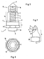
- Fig. 1 shows an electrical contact stud 1 according to the invention in side view with a shank 2, connected to a contact flange 3, wherein the contact flange 3 can be fastened to a workpiece 11 (not depicted) with the aid of a welding portion 23 and a conical projection 9.
- the contact flange 3 produces on one of its sides a mechanical contact with the workpiece and on the other side an electrical contact with a contact shoe 21 (not depicted) with the aid of its contact face 4.
- the shank 2 has an external thread 5, with which a cap nut 12 (not depicted) can be fastened.
- Contact studs 1 of this kind typically have a T6 external thread and are tightened with a torque of 6 to 8 Nm.
- the ratio of the thickness DF of the contact flange to the diameter DS of the shank is approximately 1:1. This enables the electrical contact stud 1 to be gripped by a stud setting machine in a simple manner and an adequately good electrical contact to be achieved between stud setting machine and electrical contact stud during stud welding.
- the shank 2 has a bezel 10 on its open end.
- the ratio of the inclination SA of the external thread to the diameter DS of the shank 2 is 1:3. This large ratio is particularly suitable for screwing down cap nuts 12 made of plastics material.
- Fig. 2 shows the electrical contact stud 1 according to the invention according to Fig. 1 in cross-section.
- the shank 2 and the diameter DS of the shank 2 can be seen, as well as the tool engagement region 20 with which the electrical contact stud 1 can be gripped by a tool (not depicted).
- Fig. 3 shows a cap nut 12 according to the invention with a thread orifice 13 containing an internal thread 6, wherein the ratio of the inclination SI of the internal thread 6 to the diameter DG of the thread orifice 13 is approximately 1:3.
- Cap nuts 12 of this kind typically have an M6 internal thread 6 and are tightened with approximately 9.6 Nm.
- the cap nut 12 has a tool engagement region 19, with which the cap nut 12 can be gripped by a tool (not depicted).
- the cap nut 12 has a cap 16 with a centring point 7, with which the cap nut 12, and the electrical contact stud 1, onto which the cap nut 12 is screwed, can be gripped.
- a recess 22 on a sealing flange 8 of the cap nut 12 forms a sealing lip 15, with which a particularly efficient seal of the contact face 4 of the electrical contact stud 1 is effected.
- Fig. 4 shows the cap nut 12 according to the invention according to Fig. 3 in cross-section with the thread orifice 13, the diameter DG of the thread orifice 13 and the tool engagement region 19.
- the electrical contact system according to the invention is shown in Fig. 5 in side view.
- the cap nut 12 according to the invention made of plastics material can be seen with the centring point 17, the cap 16, the tool engagement region 19 and the sealing flange 8, as well as the electrical contact stud 1 according to the invention with the shank 2, the external thread 5, the contact face 4, the contact flange 3, which has a tool engagement region 20 and the welding portion 23 with the conical projection 9.
- the cap nut 12 is screwed onto the contact stud 1 and the contact face 4 is protected by the sealing flange 8.
- Fig. 6 shows the electrical contact system according to the invention according to Fig. 5 in cross-section with the tool engagement regions 19, 20 and the shank 2.
- the sealing flange 8 which has a sealing lip 15, produced by an obtuse-angled, conical recess 22, can be seen.
- the sealing lip 15 is pressed against the contact face 4, whereby a deformation 14 is caused.
- the deformation effects on the one hand a seal and on the other hand, owing to the elastic deformation of the cap nut 12, self-locking of the cap nut 12.
- Fig, 8 shows the method according to the invention for fastening an electrical contact to a workpiece 11 to be painted. The possible sequences are illustrated in the rows.
- the cap nut 12 is first partially screwed onto the electrical contact stud 1. Then the contact stud 1 is welded onto the workpiece 11, here designed as sheet metal. With the aid of the holding tongs 18 the electric current for welding is transferred onto the electrical contact stud 1. The cap nut 12 is subsequently firmly screwed onto the contact stud 1 for sealing. Then painting takes place. The cap nut 12 is subsequently loosened, so that an electrical contact shoe 21 can be inserted, which by pressing is finally electrically contacted with the contact face 4 with the aid of the cap nut 12.
- the cap nut 12 is first firmly screwed onto the contact stud 1.
- the contact stud 1 is held by the holding tool 18 and fastened to the workpiece 11 by a welding process. Then painting takes place.
- the cap nut 12 is partially loosened and the contact shoe 21 is inserted. By tightening the cap nut 12 with a torque of for example approximately 8 Nm the contact shoe 21 is fastened and well contacted electrically with the contact face 4.
- the contact stud 1 is held by the holding tool 18 and welded on.
- the cap nut 12 is subsequently screwed down. Then painting takes place.
- the contact shoe 21 is inserted in the described manner.
- the invention relates to an electrical contact stud 1, a cap nut 12 made of plastics material, an electrical contact system for fastening an electrical contact, as well as a method for fastening an electrical contact to a workpiece 11 to be painted.
- the invention is characterised firstly in that the cap nut is made of plastics material and can therefore be produced economically.
- the required maximum torques for generating the electrical and mechanical contact can be comparatively small, can be in particular 8 Nm, whereby fastening an electrical contact is made possible even with thin sheets of metal with sheet metal thicknesses of less than 0.5 mm without deformations.
Landscapes
- Connections Effected By Soldering, Adhesion, Or Permanent Deformation (AREA)
- Application Of Or Painting With Fluid Materials (AREA)
- Gripping Jigs, Holding Jigs, And Positioning Jigs (AREA)
- Connections By Means Of Piercing Elements, Nuts, Or Screws (AREA)
Abstract
Description
- The Invention relates to an electrical contact system, in particular for fastening an electrical earth contact, comprising an electrical contact stud with a shank, having an external thread, and an adjoining contact flange with a contact face facing the shank, and a cap nut for receiving the electrical contact stud; and a method for fastening an electrical contact to a workpiece to be painted.
- A typical case of application for this is in automotive construction, where threaded studs, which can be welded on, soldered on or riveted, are used as electrical contact studs for fastening an electrical contact.
-
DE 197 41 380 A1 discloses a safety system for electric circuits wherein a fuse and a cable lug are fastened to a terminal connector by means of a nut consisting of electrically insulating plastic material. The nut has a through bore which is provided with an inner thread. - A plastic locking nut with a sealing flange is known from
US-A-3 030 997 . The nut is adapted to effect a liquid-tight seal with a screw to which it is applied and with the surface against which it is tightened. -
US-A-5 207 588 discloses an electrical grounding stud which includes a body portion disposed between, and integrally joining, a threaded stud portion and a riveting portion. The body portion includes a flange which extends generally radially from the body portion and includes a panel engaging surface and a lug engaging surface. The electrical grounding stud is adapted to be riveted to a plastically deformable electrically conductive panel. A protective cap is adapted to positively engage the stud portion and the lug engaging surface of the flange, thereby preventing paint, coatings and the like from contacting the stud portion or the surface. When a grounding lug is attached to the stud portion the protective cap is simply removed and discarded, and the grounding lug is secured to the stud portion by a metal nut for performing the function of securing the grounding lug to the electrical grounding stud. -
EP-A-0 641 944 discloses a grounding stud and nut sub-assembly wherein the nut has a thickened washer portion and a through bore provided with a swaged, flattened or distorted thread to make it a prevailing torque nut to hold the final assembly securely in place and to strip paint from the threads of the stud in an interim step during assembly. The stud also has a washer portion to protect the weld gun collet from welding heat during welding of the stud to a substrate and to achieve a stand off of a ground wire from the substrate. - From
EP 0 640 404 A1 an electrical contact system according to the preamble ofclaim 1 and a method is known, by which an electrical contact between a contact shoe and a sheet of metal to be painted is produced with the aid of a threaded stud and a cap nut. The cap nut is herein used in two ways. On the one hand the cap nut protects the threaded stud from being coated with paint during the painting process and on the other hand with the aid of the cap nut a contact shoe is fastened to the threaded stud. The advantage of this method, which uses metal cap nuts, is that by using the cap nut both as covering cap and as fastening element unnecessary waste in the form of covering caps covered with paint is avoided, as described in the prior art, for example ofEP 0 243 078 B1 . - A disadvantage of the known method is that the cap nut is a relatively expensive component if it is made of metal and that it has to be tightened with a large torque against the contact shoe, so that it does not come loose. However, large torques or large forces present a problem with mechanically sensitive workpieces, such as, for example thin sheets of metal, as they can cause deformations or damage to the workpiece when the nut is tightened.
- It is therefore the object of the present invention to create economically an electrical contact system and a method for fastening an electrical contact, whereby electrical contacts can be fastened to particularly sensitive workpieces, for example thin sheets of metal.
- This object is achieved according to the invention by an electrical system with the features according to
claim 1 and by a method of fastening an electrical contact to a workpiece to be painted using the electrical contact system with the steps defined inclaim 22. Particular features and advantageous configurations, which can occur individually or in combination, are the subject of the respective dependent claims. - A substantial feature of the invention, which has an effect in all the components of the system, is the use of a cap nut made of a plastics material for fastening an electrical contact, which has so far not been considered owing to the electrically insulating property of most plastics materials. Tests have, though, surprisingly shown that the transition resistance of the system according to the invention is only minimally greater than that of completely metal systems, and in fact irrespective of whether an electrically conductive or an electrically insulating plastics material is chosen.
- The electrical contact the system according to the invention, in particular for fastening an electrical earth contact, comprises an electrical contact stud with a shank which has an external thread and an adjoining contact flange with a contact face facing the shank, and a cap nut having a cap and a front end with a thread orifice, the thread orifice of the cap nut containing an internal thread designed for receiving the external thread of the shank of the stud, wherein the cap nut is made of plastics material, and wherein the front end has a sealing flange with a sealing lip, which engages the contact face and is elastically deformable to create a seal with the contact face, when the cap nut is screwed onto the shank and tightened with a torque of at least 1 Nm, maximum 4 Nm against the contact flange.
- An advantage of the invention is that the sealing flange achieves a particularly good seal against penetration of paint, so that the electrical contact faces are protected from paint which could make the electrical contact heavier.
- With the aid of the electrical contact stud a mechanical and electrical contact is produced on a workpiece, in particular on a sheet of metal. The contact stud can have a diameter between 4 and 10 mm, in particular between 6 and 8 mm. With the aid of the external thread on the shank a cap nut can be screwed drown, with which the electrical contact, in particular an electrical contact shoe, is fastened. The electrical contact is produced between the contact shoe and the contact face facing the shank. The transition resistance mainly depends of these two surfaces, so the electrical properties of the cap nut do not matter.
- According to the invention for producing an electrical contact only comparatively low torques are required, so electrical contacts can be fastened even to very thin sheets of metal, in particular also on sheets of metal with thicknesses < 0.6 mm, preferably < 0.5 mm. With the aid of the contact flange the electrical contact stud is fastened over a wide area on a workpiece, in particular a sheet of metal. The larger torques customary with electrical contacts in the prior art serve mainly for securing against loosening of the nut, which can be achieved with plastics material nuts by constructive measures for achieving self-locking without torques of this kind. Basically, however, comparably large torques as with metal nuts can also be applied with cap nuts according to the invention, if this is required or desired.
- The contact flange thus has on the one hand the purpose of achieving adequate mechanical strength of the contact stud on the workpiece and on the other hand the purpose of making available a sufficiently large contact area for an electrical contact.
- In one configuration of the invention the ratio of the inclination of the external thread to the diameter of the shank is at least 1:5, in particular at least 1:4, preferably approximately 1:3. In comparison to electrical contact studs for metal cap nuts a ratio of this kind of the inclination of the external thread to the diameter of the shank is very much larger. Owing to a ratio of this kind the thread of a cap nut made of plastics material is prevented from being pulled out.
- In an advantageous configuration of the invention the ratio of the thickness of the contact flange to the diameter of the shank is at least 1:2, in particular 1:1.5, preferably approximately 1:1. By means of contact flanges of this kind of thickness reliable gripping of the electrical contact stud by holding tongs is made possible. Lateral tilting is prevented. The good electrical contact between electrical contact stud and the holding tongs necessary in a stud welding method with arc is guaranteed.
- In a particular configuration of the electrical contact stud according to the invention the contact flange has on its side opposite the contact face a welding portion, preferably with a blunt conical projection. With the aid of the welding portion a welding connection is produced between the contact flange and a workpiece, in particular a sheet of metal. With the aid of the conical projection igniting a defined arc is made possible during the stud welding process. These parts are no different from those in customary earth studs for welding, as known in the prior art.
- In an advantageous configuration of the invention the contact flange has a customary tool engagement region. With the aid of the tool engagement region the electrical contact stud can be gripped by a tool and the cap nut screwed down, without the workpiece, to which the electrical contact stud is fastened, being under mechanical strain. In addition the tool engagement region can be used to tighten the cap nut if the electrical contact stud has not yet been fastened to the workpiece and the contact face of the electrical contact stud is to be protected by a cap nut.
- In a special configuration of the electrical contact stud according to the invention the shank has a bezel on its open end. With the aid of the bezel on the one hand screwing down the cap nut is made easier and on the other hand the danger of damage by sharp edges is avoided.
- In a particularly advantageous configuration of the invention the electrical contact stud is provided with a particularly corrosion-proof and electrically contact-convening coating, in particular a tin-zinc alloy. By means of a coating of this kind, which can be applied, for example, by galvanising, ageing processes of the contact faces, which could lead to an increase in the contact resistance and therefore to a reduced conductivity, are suppressed.
- According to the invention the internal thread is designed in such a way and the material of the cap nut is of such a kind that the cap nut can be tightened on a corresponding external thread against a contact face with a torque of at least 4 Nm, in particular 6 Nm, preferably 8 Nm.
- The design and the material of the cap nut are chosen in such a way that torques of this kind can be absorbed. These torques are definitely in the range of torques normally used with metal cap nuts. However, plastics material nuts can be designed in such a way that self-locking against accidental loosening begins even with lower torques. As the electrical contact does not necessarily require large torques, the effect of torques or of forces on the workpiece can be reduced without the danger of loosening the nut. The torques used are nevertheless adequate to produce a good electrical contact between an electrical contact shoe and the contact face with the cap nut.
- As the cap nut consists of plastics material, for its part it does not contribute to the electrical contact. It simply presses the contact shoe against the contact face. The pressure forces generated by the application of a torque on the cap nut are possibly smaller in comparison with metal cap nuts, but contrary to expectation are adequate for a good electrical contact. Metal cap nuts do not require a higher torque owing to the electrical resistance, but in order to effect self-locking of the cap nut. The high torques are not required for producing a smooth electrical contact and place unnecessary strain on the connection between contact stud and workpiece.
- In an advantageous configuration of the cap nut made of plastics material the ratio of the inclination of the internal thread to the diameter of the thread orifice is at least 1:5, in particular at least 1:4, preferably approximately 1:3. In order to guarantee adequate strength of the cap nut for the required torques and to prevent the internal thread being pulled out, ratios of this kind of the inclination of the internal thread to the diameter of the thread orifice are advantageous. By means of a ratio of this kind it is prevented that the cap nut is pulled out owing to excess stress. In general a larger ratio is advantageous for firmer plastics materials; a smaller ratio is necessary for softer plastics materials. With plastics material nuts, owing to the elasticity of the material, a ratio of this size is adequate to achieve self-locking.
- If it is desired that the cap nut contributes to the electrical contact, according to the invention the cap nut is made of conductive plastics material. The plastics material of the cap nut can be provided with enclosed metal filaments which can be incorporated into the moulding compound in a known manner during injection moulding. The distribution of the metal filaments in the plastics material can be random. This configuration of the cap nut will provide, in comparison with a cap nut made of metal, a sufficient conductive cross-section for the subsequent use as earth terminal. A smaller dimension with which the cap nut can be screwed onto the stud produces a completely connected contact face between the internal screw thread of the cap nut and the external thread of the stud which contributes considerably to increasing the conductive cross-section. In addition to direct introduction of the electric current into the flange of the stud from the cable lug, the current can also flow into the cap nut and via the internal thread and the external thread into the threaded shank of the stud.
- In a preferred configuration according to the invention the cap nut is made of a plastics material which can withstand particular mechanical strain, in particular of polyamide reinforced by glass fibre. The proportion of glass fibre in the plastics material is at least 10%, in particular at least 20%, preferably approximately 35% of the weight. Owing to the glass fibres a particular strength of the plastics material is achieved, which allows absorption of the necessary torques by the cap nut.
- In another advantageous configuration according to the invention the cap has a centring point, as is known per se as an assembly aid for components of this kind made of plastics material. With the aid of the centring point the cap nut can be centred during screwing down and the electrical contact stud, onto which the cap nut is screwed, can be centred during gripping for the placing process.
- According to the invention it is advantageous to design the front end with an obtuse-angled, conical recess, which forms outwardly a kind of sealing lip. With the aid of the sealing lip a particularly good seal against paint is produced. Alternatively the sealing lip is formed by at least one bridge, which runs along the periphery of the sealing flange on the front end of the cap nut.
- In a special configuration of the cap nut according to the invention the internal thread is formed with smaller dimensions. By means of the thus formed internal thread particularly good self-locking of the cap nut is generated, which makes independent loosening of the cap nut from an electrical contact stud more difficult or avoids it.
- In a further special configuration of the cap nut according to the invention the cap has a tool engagement region. With the aid of the tool engagement region the cap nut is gripped by a tool and can be tightened. The tool engagement region can be provided in cross-section by a hexagon.
- The electrical contact system according to the invention allows fastening of an electrical contact to a workpiece with low transition resistance in spite possibly of comparatively low torques. The cap nut made of plastics material makes large torques, which are necessary, for example, with metal cap nuts, unnecessary. It is simultaneously capable of effecting adequately large pressing forces, which are necessary for constructing an electrical contact. With the aid of the electrical contact system the effects of forces or torques during fastening of the electrical contact onto the workpiece are reduced. This enables electrical contacts to be fastened even with thin sheets of metal with sheet metal thicknesses of less than 0.6 mm or even less than 0.5 mm. A plastics material nut with complex structure can therein be economically produced and has a lower weight than a metal nut.
- In an advantageous configuration of the contact system according to the invention to produce self-locking the inclination of the internal thread is different from the inclination of the external thread. Owing to the different inclinations the internal thread of the cap nut is elastically deformed, whereby friction forces between cap nut and electrical contact stud are reinforced. The incommensurability of the two thread inclinations effects further protection with respect to undesired loosening of the nut from the electrical contact stud.
- In a further advantageous configuration of the electrical contact system according to the invention for producing self-locking the diameter of the thread on the shank is at least 2%, in particular at least 6%, preferably 8% larger than the diameter of the thread orifice. Owing to the difference in diameter the cap nut is braced on the electrical contact stud. In this way additional friction forces are generated for self-locking and a low transition resistance is achieved when the cap nut is made of conductive plastics material.
- The method according to the invention for fastening an electrical contact to a workpiece to be painted using an electrical contact stud, in particular an electrical contact stud according to the invention, and a cap nut, in particular a cap nut according to the invention, comprises the following method steps: the cap nut is tightened on the contact stud with a torque of at least 1 Nm, maximum 4 Nm, preferably approximately 3 Nm; the contact stud is fastened to the workpiece; paint is applied to the workpiece; the cap nut is loosened from the contact stud; an electrical contact shoe is placed in between the flange and the cap nut; the electrical contact shoe is pressed by tightening the cap nut with a torque of more than 4 Nm, preferably , more than 6 Nm, in particular approximately 8 Nm.
- The cap nut has on the one hand the function of protecting the contact stud from paint and on the other hand with it the mechanical and therefore the electrical contact is produced. The torques used are smaller by comparison with known methods, whereby application of the method can be carried out even with very thin sheets of metal.
- The sequence of the steps of the method can be partially interchanged. In particular the electrical contact can first be fastened, whereupon the cap nut is tightened. In any case it is important that the cap nut is tightened to the contact stud before the paint is applied, so that the contact stud is protected from paint. With the aid of the method according to the invention electrical contacts are generated which are comparable in quality to the contacts produced with metal cap nuts. The respective electrical contact resistances coincide to within a few percent.
- The contact stud can be fastened to the workpiece by welding, soldering or riveting.
- The cap nut made of plastics material can be tinted in a simple manner by a corresponding additive to the plastics material. The colour can be enlisted for identifying the cap nut, in particular its task or its size.
- In a particular configuration of the invention the cap nut is elastically or plastically deformed on first tightening. Owing to the elastic or plastic deformation a particularly good seal is achieved, whereby the electrical contact stud is particularly effectively protected from paint. By an elastic or plastic deformation, in particular during the second tightening particularly good self-locking of the cap nut is further effected after final assembly.
- Further advantageous configurations and characteristic features, which can occur individually or in combination, are described using the following drawings. The drawings are not, however, intended to restrict the invention, but are intended to depict the invention only as an example.
-
Fig. 1 shows an electrical contact stud according to the invention in side view. -
Fig. 2 shows an electrical contact stud according to the invention according toFig. 1 in cross-section. -
Fig. 3 shows a cap nut according to the invention in side view, half cut open. -
Fig. 4 shows a cap nut according to the invention according toFig. 3 in cross-section. -
Fig. 5 shows an electrical contact system according to the invention in side view. -
Fig. 6 shows an electrical contact system according to the invention according toFig. 5 in cross-section. -
Fig. 7 shows a detail from the electrical contact system according to the invention according toFig. 5 in longitudinal section, and -
Fig. 8 shows various method sequences of the method according to the invention for fastening an electrical contact to a workpiece to be painted using an electrical contact stud and a cap nut. -
Fig. 1 shows anelectrical contact stud 1 according to the invention in side view with ashank 2, connected to acontact flange 3, wherein thecontact flange 3 can be fastened to a workpiece 11 (not depicted) with the aid of awelding portion 23 and aconical projection 9. Thecontact flange 3 produces on one of its sides a mechanical contact with the workpiece and on the other side an electrical contact with a contact shoe 21 (not depicted) with the aid of itscontact face 4. Theshank 2 has anexternal thread 5, with which a cap nut 12 (not depicted) can be fastened. Contactstuds 1 of this kind typically have a T6 external thread and are tightened with a torque of 6 to 8 Nm. - The ratio of the thickness DF of the contact flange to the diameter DS of the shank is approximately 1:1. This enables the
electrical contact stud 1 to be gripped by a stud setting machine in a simple manner and an adequately good electrical contact to be achieved between stud setting machine and electrical contact stud during stud welding. Theshank 2 has abezel 10 on its open end. The ratio of the inclination SA of the external thread to the diameter DS of theshank 2 is 1:3. This large ratio is particularly suitable for screwing downcap nuts 12 made of plastics material. With the aid of theconical projection 9 an arc is generated during stud welding, starting from the point of theconical projection 9. Theportion 23 is pressed into the liquid molten mass after the workpiece has been heated. -
Fig. 2 shows theelectrical contact stud 1 according to the invention according toFig. 1 in cross-section. Theshank 2 and the diameter DS of theshank 2 can be seen, as well as thetool engagement region 20 with which theelectrical contact stud 1 can be gripped by a tool (not depicted). -
Fig. 3 shows acap nut 12 according to the invention with athread orifice 13 containing aninternal thread 6, wherein the ratio of the inclination SI of theinternal thread 6 to the diameter DG of thethread orifice 13 is approximately 1:3.Cap nuts 12 of this kind typically have an M6internal thread 6 and are tightened with approximately 9.6 Nm. Thecap nut 12 has atool engagement region 19, with which thecap nut 12 can be gripped by a tool (not depicted). In addition thecap nut 12 has acap 16 with acentring point 7, with which thecap nut 12, and theelectrical contact stud 1, onto which thecap nut 12 is screwed, can be gripped. Arecess 22 on a sealingflange 8 of thecap nut 12 forms a sealinglip 15, with which a particularly efficient seal of thecontact face 4 of theelectrical contact stud 1 is effected. -
Fig. 4 shows thecap nut 12 according to the invention according toFig. 3 in cross-section with thethread orifice 13, the diameter DG of thethread orifice 13 and thetool engagement region 19. - The electrical contact system according to the invention is shown in
Fig. 5 in side view. Thecap nut 12 according to the invention made of plastics material can be seen with thecentring point 17, thecap 16, thetool engagement region 19 and the sealingflange 8, as well as theelectrical contact stud 1 according to the invention with theshank 2, theexternal thread 5, thecontact face 4, thecontact flange 3, which has atool engagement region 20 and thewelding portion 23 with theconical projection 9. Thecap nut 12 is screwed onto thecontact stud 1 and thecontact face 4 is protected by the sealingflange 8. -
Fig. 6 shows the electrical contact system according to the invention according toFig. 5 in cross-section with thetool engagement regions shank 2. - Protection of the
contact face 4 from being covered with paint is shown in the detailed view ofFig. 7 . The sealingflange 8, which has a sealinglip 15, produced by an obtuse-angled,conical recess 22, can be seen. The sealinglip 15 is pressed against thecontact face 4, whereby adeformation 14 is caused. The deformation effects on the one hand a seal and on the other hand, owing to the elastic deformation of thecap nut 12, self-locking of thecap nut 12. -
Fig, 8 shows the method according to the invention for fastening an electrical contact to aworkpiece 11 to be painted. The possible sequences are illustrated in the rows. - In the top row the
cap nut 12 is first partially screwed onto theelectrical contact stud 1. Then thecontact stud 1 is welded onto theworkpiece 11, here designed as sheet metal. With the aid of the holdingtongs 18 the electric current for welding is transferred onto theelectrical contact stud 1. Thecap nut 12 is subsequently firmly screwed onto thecontact stud 1 for sealing. Then painting takes place. Thecap nut 12 is subsequently loosened, so that anelectrical contact shoe 21 can be inserted, which by pressing is finally electrically contacted with thecontact face 4 with the aid of thecap nut 12. - In the second row the
cap nut 12 is first firmly screwed onto thecontact stud 1. Thecontact stud 1 is held by the holdingtool 18 and fastened to theworkpiece 11 by a welding process. Then painting takes place. Thecap nut 12 is partially loosened and thecontact shoe 21 is inserted. By tightening thecap nut 12 with a torque of for example approximately 8 Nm thecontact shoe 21 is fastened and well contacted electrically with thecontact face 4. - In the third line the
contact stud 1 is held by the holdingtool 18 and welded on. Thecap nut 12 is subsequently screwed down. Then painting takes place. Thecontact shoe 21 is inserted in the described manner. - The invention relates to an
electrical contact stud 1, acap nut 12 made of plastics material, an electrical contact system for fastening an electrical contact, as well as a method for fastening an electrical contact to aworkpiece 11 to be painted. The invention is characterised firstly in that the cap nut is made of plastics material and can therefore be produced economically. In addition the required maximum torques for generating the electrical and mechanical contact can be comparatively small, can be in particular 8 Nm, whereby fastening an electrical contact is made possible even with thin sheets of metal with sheet metal thicknesses of less than 0.5 mm without deformations.
Claims (22)
- Electrical contact system, in particular for fastening an electrical earth contact, comprising an electrical contact stud (1) having shank (2) with an external thread (5), and an adjoining contact flange (3) with a contact face (4) facing the shank, and a cap nut (12) having a cap (16) and a front end (17) with a thread orifice (13), the thread orifice (13) containing an internal thread (6) designed for receiving the external thread (5) of the shank (2) of the stud (1), characterised in that the cap nut (12) is made of plastics material, and that the front end (17) of the cap nut (12) has a sealing flange (8) with a sealing lip (15), which engages the contact face (4) and is elastically deformable to create a seal, when the cap nut (12) is screwed onto the shank and tightened with a torque of at least 1 Nm, maximum 4 Nm against the contact flange (3).
- Electrical contact system according to claim 1, characterised in that, to produce self-locking, the inclination of the internal thread (6) is different from the inclination of the external thread (5).
- Electrical contact system according to any one of claims 1 or 2, characterised in that the internal thread (6) of the cap nut (12) is formed with a dimension smaller than that of the external thread (5) of the shank (2).
- Electrical contact system according to any one of claims 1 or 2, characterised in that, to produce self-locking, the diameter (DS) of the shank (2) is at least 2%, in particular at least 6%, preferably approximately 8% larger than the diameter (DG) of the thread orifice (13).
- Electrical contact system according to any one of the preceding claims, characterised in that the ratio of the inclination (SA) of the external thread (5) to the diameter (DS) of the shank (2) is at least 1:5, in particular at least 1:4, preferably approximately 1:3.
- Electrical contact system according to any one of the preceding claims, characterised in that the ratio of the thickness (DF) of the contact flange (3) to the diameter (DS) of the shank (2) is at least 1:2, in particular 1:1.5, preferably approximately 1:1.
- Electrical contact system according to any one of the preceding claims, characterised in that the contact flange (3) has on its side opposite the contact face a welding portion (23), preferably with a blunt conical projection (9).
- Electrical contact system according to any one of the preceding claims, characterised in that the contact flange (3) of the stud (1) has an axial extension to form a contact face for the introduction of welding current.
- Electrical contact system according to any one of the preceding claims, characterised in that the contact flange (3) has a tool engagement region (20).
- Electrical contact system according to any one of the preceding claims, characterised in that the shank (2) has a bezel (10) on its open end.
- Electrical contact system according to any one of the preceding claims, characterised in that the contact stud (1) has a particularly corrosion-proof and electrically contact-conveying coating, in particular a tin-zinc alloy.
- Electrical contact system according to any one of the preceding claims, characterised in that the ratio of the inclination of the internal thread (6) to the diameter (DG) of the thread orifice (13) is at least 1:5, in particular at least 1:4, preferably approximately 1:3.
- Electrical contact system, according to any one of the preceding claims, characterised in that the cap nut (12) is made of conductive plastics material.
- Electrical contact system according to claim 13, characterised in that the conductivity of the plastics material is created by an enclosed metal element.
- Electrical contact system according to claim 14, characterised in that enclosed metal elements are formed as metal filaments.
- Electrical contact system according to any one of the preceding claims, characterised in that the cap nut (12) is made of a plastics material with particular resistance to mechanical strain, in particular polyamide reinforced by glass fibres.
- Electrical contact system according to claim 16, characterised in that the plastics material contains at least 10%, in particular at least 20%, preferably approximately 35% glass fibres.
- Electrical contact system according to any one of the preceding claims, characterised in that the cap (16) has a centring point (7).
- Electrical contact system according to any one of the preceding claims, characterised in that the diameter of the sealing flange (8) of the cap nut (12) does not exceed the diameter of the contact face (4) of the flange (3).
- Electrical contact system according to any one of the preceding claims, characterised in that the front end (17) of the cap nut (12) has a concave surface or an obtuse-angled, conical recess (22), so the sealing lip (15) is formed on the outside.
- Electrical contact system according to any one of the preceding claims, characterised in that the cap (16) has a tool engagement region (19).
- Method of fastening an electrical contact to a workpiece (11) to be painted using an electrical contact system according to any one of the preceding comprising the following method steps:- tightening the cap nut (12) on the contact stud (1) with a torque of at least 1 Nm, maximum 4Nm, preferably approximately 3 Nm;- fastening the contact stud (1) to the workpiece (11);- applying the paint to the workpiece (11);- loosening the cap nut (12) from the contact stud (1);- intermediate placing of an electrical contact shoe (21) between the flange (3) and the cap nut (12);- pressing the electrical contact shoe (21) by tightening the cap nut (12) with a torque of more than 4 Nm, preferably more than 6 Nm, in particular maximum 8 Nm.
Applications Claiming Priority (5)
| Application Number | Priority Date | Filing Date | Title |
|---|---|---|---|
| DE10100832 | 2001-01-10 | ||
| DE2001100832 DE10100832A1 (en) | 2001-01-10 | 2001-01-10 | A capped contact stud for fastening an electrical earth contact to a metal sheet to be painted includes a stud with a shank with an external thread to receive a cap nut with an internal thread, a sealing flange protecting a contact face |
| DE10138800 | 2001-08-14 | ||
| DE10138800A DE10138800A1 (en) | 2001-08-14 | 2001-08-14 | A capped contact stud for fastening an electrical earth contact to a metal sheet to be painted includes a stud with a shank with an external thread to receive a cap nut with an internal thread, a sealing flange protecting a contact face |
| PCT/GB2002/000080 WO2002056422A1 (en) | 2001-01-10 | 2002-01-10 | Electrical capped contact stud and method of fastening an electrical contact |
Publications (2)
| Publication Number | Publication Date |
|---|---|
| EP1350286A1 EP1350286A1 (en) | 2003-10-08 |
| EP1350286B1 true EP1350286B1 (en) | 2010-06-02 |
Family
ID=26008199
Family Applications (1)
| Application Number | Title | Priority Date | Filing Date |
|---|---|---|---|
| EP02729447A Expired - Lifetime EP1350286B1 (en) | 2001-01-10 | 2002-01-10 | Electrical capped contact stud and method of fastening an electrical contact |
Country Status (6)
| Country | Link |
|---|---|
| US (1) | US6877997B2 (en) |
| EP (1) | EP1350286B1 (en) |
| JP (1) | JP2004518250A (en) |
| AT (1) | ATE470252T1 (en) |
| DE (1) | DE60236572D1 (en) |
| WO (1) | WO2002056422A1 (en) |
Families Citing this family (17)
| Publication number | Priority date | Publication date | Assignee | Title |
|---|---|---|---|---|
| FR2865073B1 (en) * | 2004-01-08 | 2009-11-13 | Airbus France | ELECTRICAL CONNECTION DEVICE FOR MAKING A METALLIZATION POINT, SUPPORT EQUIPPED WITH SUCH A CONNECTION DEVICE, AND AIRCRAFT EQUIPPED WITH SUCH A SUPPORT |
| FR2879836B1 (en) * | 2004-12-21 | 2007-02-23 | Peugeot Citroen Automobiles Sa | DEVICE AND METHOD FOR GROUNDING AN ELECTRIC WIRE ON A METAL STRUCTURE, IN PARTICULAR AN ALUMINUM CASE FOR A MOTOR VEHICLE |
| DE102006056065B4 (en) | 2006-11-20 | 2018-08-09 | Newfrey Llc | Pre-assembled contacting unit and mounting arrangement |
| ATE533963T1 (en) * | 2008-01-24 | 2011-12-15 | Meflex Telecontrol Gmbh & Co Kg | TERMINATION CAP FOR A DRIVE CABLE, DRIVE CABLE, METHOD FOR PRODUCING A TERMINATION CAP AND METHOD FOR PRODUCING A DRIVE CABLE |
| US8641342B2 (en) | 2008-07-09 | 2014-02-04 | Newfrey Llc | Stud for stud welding |
| DE202008017727U1 (en) * | 2008-07-09 | 2010-05-27 | Newfrey Llc, Newark | Stud for stud welding |
| EP2342724B1 (en) * | 2008-10-28 | 2011-12-14 | Koninklijke Philips Electronics N.V. | Reuse of screw thread |
| US7892049B1 (en) * | 2009-08-18 | 2011-02-22 | GM Global Technology Operations LLC | Electrical connector assemblies |
| JP5362673B2 (en) * | 2010-07-27 | 2013-12-11 | 株式会社キンキ | Detachment method of filling member |
| US8633391B2 (en) | 2011-06-14 | 2014-01-21 | Cooper Technologies Company | Protective device |
| DE102012005786A1 (en) * | 2012-03-21 | 2013-09-26 | Emitec Gesellschaft Für Emissionstechnologie Mbh | Non-rotating electrical connection, in particular for an electrically heatable honeycomb body |
| DE102013007036A1 (en) * | 2013-04-24 | 2014-10-30 | Newfrey Llc | Contacting device for an electrical contact arrangement and method for its production |
| CN103307081B (en) * | 2013-06-26 | 2015-09-30 | 靖江市新程汽车零部件有限公司 | Assembled nut and projection welding method thereof |
| JP6597480B2 (en) | 2016-05-24 | 2019-10-30 | 株式会社豊田自動織機 | Bus bar assembly structure and battery module |
| DE102018203800B4 (en) * | 2018-03-13 | 2019-11-21 | Te Connectivity Germany Gmbh | Contact pin and arrangement for connecting electrical conductors made of copper and aluminum |
| US10729043B1 (en) * | 2019-04-17 | 2020-07-28 | The Boeing Company | Vacuum cap seal installation |
| DE102023105840A1 (en) | 2023-03-09 | 2024-09-12 | Bayerische Motoren Werke Aktiengesellschaft | Method and device for temporarily attaching an external voltage source to a vehicle body component |
Family Cites Families (13)
| Publication number | Priority date | Publication date | Assignee | Title |
|---|---|---|---|---|
| US3030997A (en) * | 1958-06-10 | 1962-04-24 | Prestole Corp | Plastic locking nut with sealing flange |
| US4013110A (en) * | 1975-06-12 | 1977-03-22 | Bjd Industries, Inc. | Locking thread |
| US5207588A (en) * | 1980-02-02 | 1993-05-04 | Multifastener Corporation | Electrical grounding stud |
| US5441417A (en) * | 1981-01-28 | 1995-08-15 | Multifastener Corporation | Electrical grounding stud |
| US4666190A (en) * | 1984-07-13 | 1987-05-19 | Sekisui Kagaku Kogyo Kabushiki Kaisha | Tube joint |
| US4883399A (en) * | 1988-12-05 | 1989-11-28 | Maclean-Fogg Company | Plastic encapsulated nut and washer assembly |
| DE4005836C2 (en) * | 1990-02-23 | 1999-10-28 | Stolberger Metallwerke Gmbh | Electrical connector pair |
| ATE159870T1 (en) * | 1993-08-24 | 1997-11-15 | Nedschroef Plettenberg Gmbh | COVER CAP |
| US5442133A (en) * | 1993-09-08 | 1995-08-15 | Emhart Inc. | Grounding stud/nut |
| US5590992A (en) * | 1995-03-08 | 1997-01-07 | Aluminum Company Of America | Cover for a bolt and nut |
| US5791848A (en) * | 1997-04-24 | 1998-08-11 | Mcgard, Inc. | Structure for converting standard drive fastener to security fastener |
| US5944465A (en) * | 1997-08-04 | 1999-08-31 | Janitzki; Bernhard M. | Low tolerance threaded fastener |
| DE19741830B4 (en) * | 1997-09-23 | 2007-07-12 | Wilhelm Pudenz Gmbh | Safety system for protecting electrical circuits, especially in vehicles |
-
2002
- 2002-01-10 JP JP2002556978A patent/JP2004518250A/en active Pending
- 2002-01-10 WO PCT/GB2002/000080 patent/WO2002056422A1/en not_active Ceased
- 2002-01-10 EP EP02729447A patent/EP1350286B1/en not_active Expired - Lifetime
- 2002-01-10 AT AT02729447T patent/ATE470252T1/en not_active IP Right Cessation
- 2002-01-10 DE DE60236572T patent/DE60236572D1/en not_active Expired - Lifetime
-
2003
- 2003-07-02 US US10/612,433 patent/US6877997B2/en not_active Expired - Fee Related
Also Published As
| Publication number | Publication date |
|---|---|
| WO2002056422A8 (en) | 2002-11-14 |
| JP2004518250A (en) | 2004-06-17 |
| WO2002056422A1 (en) | 2002-07-18 |
| DE60236572D1 (en) | 2010-07-15 |
| EP1350286A1 (en) | 2003-10-08 |
| US6877997B2 (en) | 2005-04-12 |
| ATE470252T1 (en) | 2010-06-15 |
| US20040062622A1 (en) | 2004-04-01 |
Similar Documents
| Publication | Publication Date | Title |
|---|---|---|
| US6877997B2 (en) | Electrical capped contact stud and method of fastening an electrical contact | |
| US8287219B2 (en) | Fastening arrangement | |
| EP1017129B1 (en) | Stud electrical connection | |
| US5442133A (en) | Grounding stud/nut | |
| US7156670B2 (en) | Electrical capped contact stud and method of fastening an electrical contact | |
| US5644830A (en) | Method of forming electrical connection | |
| CN101868884B (en) | Contact-making unit, attachment method and screwing tool for carrying out the method | |
| US8701285B2 (en) | Method for producing a hollow fastener element, electrical connections and component assembly | |
| US6623315B1 (en) | Cable terminal and cable assembly | |
| US6126493A (en) | Electrical fastener | |
| US5772455A (en) | Combination messenger strand ground and cable lashing wire clamp | |
| JPS58130710A (en) | Method of terminating cable shield and cable shield termination assembly | |
| CA2118190A1 (en) | Dual-function fastener and method of use | |
| US7788802B2 (en) | Method of fastening an electrical contact | |
| KR20150087806A (en) | Earth bold | |
| CN104968950B (en) | Grounding nut | |
| US6433278B1 (en) | Attachment device with cap | |
| US12444862B2 (en) | Electrical connection element for a form-fitted or welding attachment to a sheet metal part | |
| US20240313434A1 (en) | Connection Arrangement, Connection System and Method for Connecting Two Electrical Conductors | |
| US6790078B1 (en) | Contact protection housing, injection pump and method for mounting a contact protection housing with the aid of an adapter | |
| JP3209893B2 (en) | Battery terminal | |
| WO2005025005A1 (en) | Grounding element and method for grounding | |
| JPH0763211A (en) | Loosening prevention seal nut | |
| US11739780B2 (en) | Functional element | |
| AU2019314862B2 (en) | Insert for connecting an electric connection to a wall, and protective cap for an insert |
Legal Events
| Date | Code | Title | Description |
|---|---|---|---|
| PUAI | Public reference made under article 153(3) epc to a published international application that has entered the european phase |
Free format text: ORIGINAL CODE: 0009012 |
|
| 17P | Request for examination filed |
Effective date: 20030711 |
|
| AK | Designated contracting states |
Kind code of ref document: A1 Designated state(s): AT BE CH CY DE DK ES FI FR GB GR IE IT LI LU MC NL PT SE TR |
|
| RAP1 | Party data changed (applicant data changed or rights of an application transferred) |
Owner name: NEWFREY LLC |
|
| 17Q | First examination report despatched |
Effective date: 20090804 |
|
| GRAP | Despatch of communication of intention to grant a patent |
Free format text: ORIGINAL CODE: EPIDOSNIGR1 |
|
| GRAS | Grant fee paid |
Free format text: ORIGINAL CODE: EPIDOSNIGR3 |
|
| GRAA | (expected) grant |
Free format text: ORIGINAL CODE: 0009210 |
|
| AK | Designated contracting states |
Kind code of ref document: B1 Designated state(s): AT BE CH CY DE DK ES FI FR GB GR IE IT LI LU MC NL PT SE TR |
|
| REG | Reference to a national code |
Ref country code: GB Ref legal event code: FG4D |
|
| REG | Reference to a national code |
Ref country code: CH Ref legal event code: EP |
|
| REG | Reference to a national code |
Ref country code: IE Ref legal event code: FG4D |
|
| REF | Corresponds to: |
Ref document number: 60236572 Country of ref document: DE Date of ref document: 20100715 Kind code of ref document: P |
|
| REG | Reference to a national code |
Ref country code: NL Ref legal event code: VDEP Effective date: 20100602 |
|
| PG25 | Lapsed in a contracting state [announced via postgrant information from national office to epo] |
Ref country code: SE Free format text: LAPSE BECAUSE OF FAILURE TO SUBMIT A TRANSLATION OF THE DESCRIPTION OR TO PAY THE FEE WITHIN THE PRESCRIBED TIME-LIMIT Effective date: 20100602 |
|
| PG25 | Lapsed in a contracting state [announced via postgrant information from national office to epo] |
Ref country code: AT Free format text: LAPSE BECAUSE OF FAILURE TO SUBMIT A TRANSLATION OF THE DESCRIPTION OR TO PAY THE FEE WITHIN THE PRESCRIBED TIME-LIMIT Effective date: 20100602 Ref country code: FI Free format text: LAPSE BECAUSE OF FAILURE TO SUBMIT A TRANSLATION OF THE DESCRIPTION OR TO PAY THE FEE WITHIN THE PRESCRIBED TIME-LIMIT Effective date: 20100602 |
|
| PG25 | Lapsed in a contracting state [announced via postgrant information from national office to epo] |
Ref country code: GR Free format text: LAPSE BECAUSE OF FAILURE TO SUBMIT A TRANSLATION OF THE DESCRIPTION OR TO PAY THE FEE WITHIN THE PRESCRIBED TIME-LIMIT Effective date: 20100903 Ref country code: CY Free format text: LAPSE BECAUSE OF FAILURE TO SUBMIT A TRANSLATION OF THE DESCRIPTION OR TO PAY THE FEE WITHIN THE PRESCRIBED TIME-LIMIT Effective date: 20100602 |
|
| PG25 | Lapsed in a contracting state [announced via postgrant information from national office to epo] |
Ref country code: NL Free format text: LAPSE BECAUSE OF FAILURE TO SUBMIT A TRANSLATION OF THE DESCRIPTION OR TO PAY THE FEE WITHIN THE PRESCRIBED TIME-LIMIT Effective date: 20100602 |
|
| PG25 | Lapsed in a contracting state [announced via postgrant information from national office to epo] |
Ref country code: BE Free format text: LAPSE BECAUSE OF FAILURE TO SUBMIT A TRANSLATION OF THE DESCRIPTION OR TO PAY THE FEE WITHIN THE PRESCRIBED TIME-LIMIT Effective date: 20100602 Ref country code: PT Free format text: LAPSE BECAUSE OF FAILURE TO SUBMIT A TRANSLATION OF THE DESCRIPTION OR TO PAY THE FEE WITHIN THE PRESCRIBED TIME-LIMIT Effective date: 20101004 |
|
| PLBE | No opposition filed within time limit |
Free format text: ORIGINAL CODE: 0009261 |
|
| STAA | Information on the status of an ep patent application or granted ep patent |
Free format text: STATUS: NO OPPOSITION FILED WITHIN TIME LIMIT |
|
| PG25 | Lapsed in a contracting state [announced via postgrant information from national office to epo] |
Ref country code: DK Free format text: LAPSE BECAUSE OF FAILURE TO SUBMIT A TRANSLATION OF THE DESCRIPTION OR TO PAY THE FEE WITHIN THE PRESCRIBED TIME-LIMIT Effective date: 20100602 |
|
| 26N | No opposition filed |
Effective date: 20110303 |
|
| REG | Reference to a national code |
Ref country code: DE Ref legal event code: R097 Ref document number: 60236572 Country of ref document: DE Effective date: 20110302 |
|
| PG25 | Lapsed in a contracting state [announced via postgrant information from national office to epo] |
Ref country code: MC Free format text: LAPSE BECAUSE OF NON-PAYMENT OF DUE FEES Effective date: 20110131 |
|
| REG | Reference to a national code |
Ref country code: CH Ref legal event code: PL |
|
| REG | Reference to a national code |
Ref country code: IE Ref legal event code: MM4A |
|
| PG25 | Lapsed in a contracting state [announced via postgrant information from national office to epo] |
Ref country code: CH Free format text: LAPSE BECAUSE OF NON-PAYMENT OF DUE FEES Effective date: 20110131 Ref country code: LI Free format text: LAPSE BECAUSE OF NON-PAYMENT OF DUE FEES Effective date: 20110131 |
|
| PG25 | Lapsed in a contracting state [announced via postgrant information from national office to epo] |
Ref country code: IE Free format text: LAPSE BECAUSE OF NON-PAYMENT OF DUE FEES Effective date: 20110110 |
|
| PGFP | Annual fee paid to national office [announced via postgrant information from national office to epo] |
Ref country code: GB Payment date: 20120126 Year of fee payment: 11 Ref country code: IT Payment date: 20120123 Year of fee payment: 11 |
|
| PG25 | Lapsed in a contracting state [announced via postgrant information from national office to epo] |
Ref country code: LU Free format text: LAPSE BECAUSE OF NON-PAYMENT OF DUE FEES Effective date: 20110110 |
|
| GBPC | Gb: european patent ceased through non-payment of renewal fee |
Effective date: 20130110 |
|
| PG25 | Lapsed in a contracting state [announced via postgrant information from national office to epo] |
Ref country code: TR Free format text: LAPSE BECAUSE OF FAILURE TO SUBMIT A TRANSLATION OF THE DESCRIPTION OR TO PAY THE FEE WITHIN THE PRESCRIBED TIME-LIMIT Effective date: 20100602 |
|
| PG25 | Lapsed in a contracting state [announced via postgrant information from national office to epo] |
Ref country code: ES Free format text: LAPSE BECAUSE OF FAILURE TO SUBMIT A TRANSLATION OF THE DESCRIPTION OR TO PAY THE FEE WITHIN THE PRESCRIBED TIME-LIMIT Effective date: 20100913 |
|
| PG25 | Lapsed in a contracting state [announced via postgrant information from national office to epo] |
Ref country code: GB Free format text: LAPSE BECAUSE OF NON-PAYMENT OF DUE FEES Effective date: 20130110 |
|
| PG25 | Lapsed in a contracting state [announced via postgrant information from national office to epo] |
Ref country code: IT Free format text: LAPSE BECAUSE OF NON-PAYMENT OF DUE FEES Effective date: 20130110 |
|
| PGFP | Annual fee paid to national office [announced via postgrant information from national office to epo] |
Ref country code: DE Payment date: 20140129 Year of fee payment: 13 |
|
| PGFP | Annual fee paid to national office [announced via postgrant information from national office to epo] |
Ref country code: FR Payment date: 20140117 Year of fee payment: 13 |
|
| REG | Reference to a national code |
Ref country code: DE Ref legal event code: R119 Ref document number: 60236572 Country of ref document: DE |
|
| PG25 | Lapsed in a contracting state [announced via postgrant information from national office to epo] |
Ref country code: DE Free format text: LAPSE BECAUSE OF NON-PAYMENT OF DUE FEES Effective date: 20150801 |
|
| REG | Reference to a national code |
Ref country code: FR Ref legal event code: ST Effective date: 20150930 |
|
| PG25 | Lapsed in a contracting state [announced via postgrant information from national office to epo] |
Ref country code: FR Free format text: LAPSE BECAUSE OF NON-PAYMENT OF DUE FEES Effective date: 20150202 |