EP1349666B1 - Disposable cartridge for electrostatic spray device - Google Patents
Disposable cartridge for electrostatic spray device Download PDFInfo
- Publication number
- EP1349666B1 EP1349666B1 EP02707433A EP02707433A EP1349666B1 EP 1349666 B1 EP1349666 B1 EP 1349666B1 EP 02707433 A EP02707433 A EP 02707433A EP 02707433 A EP02707433 A EP 02707433A EP 1349666 B1 EP1349666 B1 EP 1349666B1
- Authority
- EP
- European Patent Office
- Prior art keywords
- product
- high voltage
- reservoir
- cartridge
- nozzle
- Prior art date
- Legal status (The legal status is an assumption and is not a legal conclusion. Google has not performed a legal analysis and makes no representation as to the accuracy of the status listed.)
- Expired - Lifetime
Links
Images




Classifications
-
- B—PERFORMING OPERATIONS; TRANSPORTING
- B05—SPRAYING OR ATOMISING IN GENERAL; APPLYING FLUENT MATERIALS TO SURFACES, IN GENERAL
- B05B—SPRAYING APPARATUS; ATOMISING APPARATUS; NOZZLES
- B05B5/00—Electrostatic spraying apparatus; Spraying apparatus with means for charging the spray electrically; Apparatus for spraying liquids or other fluent materials by other electric means
- B05B5/16—Arrangements for supplying liquids or other fluent material
-
- B—PERFORMING OPERATIONS; TRANSPORTING
- B05—SPRAYING OR ATOMISING IN GENERAL; APPLYING FLUENT MATERIALS TO SURFACES, IN GENERAL
- B05B—SPRAYING APPARATUS; ATOMISING APPARATUS; NOZZLES
- B05B5/00—Electrostatic spraying apparatus; Spraying apparatus with means for charging the spray electrically; Apparatus for spraying liquids or other fluent materials by other electric means
- B05B5/16—Arrangements for supplying liquids or other fluent material
- B05B5/1691—Apparatus to be carried on or by a person or with a container fixed to the discharge device
Definitions
- This invention relates to a disposable cartridge for a portable electrostatic spray device designed for personal use. More particular, this invention is focused on improvements for product mixing and maintaining a superior high voltage connection.
- Kelly offers a refillable reservoir system.
- the system described by Kelly does not integrally include a nozzle with the delivery system.
- the system, as described would cross contaminate the liquid delivery system when it would be desired to use multiple liquids as Kelly's delivery system is simply a piston operated pump with a dip tube extending into the product reservoir. To avoid cross-contamination this system would necessitate an added cleaning step with a specialized cleaning solution.
- Kelly does not include a positive displacement system. Rather, Kelly has a non-continuous delivery system in that fluid is delivered in response to user actuation of lever arm 266. As such, Kelly's flow rate will be variable because the rate at which the lever is depressed may vary due to inconsistent actuation force from the user.
- Kelly's system also does not recognize the need and therefore does not offer a solution to limiting electrical current passing through the product reservoir.
- Kelly does not offer a means by which to mix the product in the reservoir.
- Noakes offers a disposable reservoir system.
- the Noakes system is not a "clean" design, as the electrode stays connected with the device and would be a common element for all reservoirs in communication with the device.
- Noakes' electrode is a source for cross-contamination between products from different reservoirs. Further, .
- Noakes' electrode design is a thin metal wire, which has an increased breakage potential. Further, the system described by Noakes is a non-continuous delivery system. Further, Noakes does not recognize or offer a solution for the problem of limiting electrical current passing through the product reservoir. Further, Noakes does not offer a method to incorporate a mixing feature in the reservoir to mix product.
- Noakes does not address the problem of removing or re-using a partially filled reservoir.
- removal of a partially filled reservoir may be messy.
- US-patent 5531384 which discloses the features of the preamble of claim 1, describes an electrostatic spray gun including a replaceable fluid container and a nozzle outlet.
- the spray gun further includes an apparatus for applying high voltage to liquid in the fluid container, and a spring loaded trigger piston for pressurizing the liquid through the outlet.
- US-patent 4549243 describes an electrostatic spraying apparatus.
- the electrostatic spraying apparatus has a hand or finger held body carrying a nozzle to which an atomizing potential is applied by means of a high voltage generator.
- the body comprises a liquid reservoir. Additionally, the body may comprise the high voltage generator so as to provide a self-contained unit.
- a disposable cartridge for an electrostatic spraying device which is configured and disposed to electrostatically charge and dispense a product from a supply to a point of dispersal.
- the electrostatic spraying device has a reservoir configured to contain the supply of product and a nozzle to disperse the product.
- the nozzle being disposed at the point of dispersal.
- the nozzle has an exit orifice.
- a channel is disposed between the reservoir and the nozzle, wherein the channel permits the electrostatic charging of the product upon the product moving within the channel.
- a positive displacement mechanism is used to move the product from the reservoir to the nozzle.
- a power source supplies an electrical charge.
- a high voltage power supply, high voltage contact, and high voltage electrode are used.
- a portion of the high voltage electrode being disposed between the reservoir and the nozzle is used to electrostatically charge the product within the channel at a charging location before the product is being dispersed from the nozzle.
- a mixing mechanism may be disposed between the reservoir and the nozzle to reconstitute any product which may have separated.
- the mixing mechanism may be a mixing ball, static mixer, disc having at least one hole, baffle having at least one opening, prop mixer.
- the high voltage contact may be spring biased in direction towards the high voltage electrode.
- the high voltage electrode may be annular to improve contact with the high voltage contact.
- a locking mechanism may be added to secure the connection between the high voltage contact and the high voltage electrode.
- a locking feature may be added to secure the disposable cartridge within the device.
- An ejection feature may be added to release the disposable cartridge from the device.
- Disposable cartridge 200 may contain a variety of product, including but not limited to, cosmetics, skin creams, and skin lotions.
- the product in disposable cartridge 200 may be positively displaced (discussed infra) and powered by gearbox/motor component.
- Gearbox/motor component may be fixed onto a left or first housing 830.
- the gearbox/motor component can be affixed into place mechanically, adhesively, or by any other suitable technique.
- Gearbox/motor component preferably comprises a precision motor 810a connected to a gearbox 810b.
- Power source 820 provides power to the device.
- An example of a suitable power source 820 includes, but is not limited to, two "AAA" type batteries.
- the power source 820 provides power to the device through the control circuit 860 the high voltage power supply 840, and then the high voltage contact 850, which contacts the disposable cartridge 200.
- High voltage power supply 840 is powered and controlled by control circuit 860 (discussed infra).
- Power-on switch 880 permits the user to cause an interruption between power source 820 and circuit control 860.
- Power-on switch 880 is designed such that voltage is supplied to the remainder of the circuit only when switch 880 is in the "ON" or closed position. Apply switch 870 permits the user to selectively activate motor 810a, thereby activating the delivery and spraying of the product.
- Gearbox/motor component has a driver 890 fastened to a shaft (not shown in Fig 7 & 8 , see Fig 1 ) of gearbox 810b, for example, with a set screw (not shown).
- Driver 890 has a number of protruding fingers, for example, three, which can fit into the matching recesses on the back of actuator 240.
- the product reservoir 220 may be formed of a conductive material and used to maintain the product reservoir at a high potential instead of having a separate conductive shield around the reservoir 220.
- a cartridge insulator 260 can prevent discharge from the conducive product reservoir 220 to points having a lower potential that are in close proximity to the product reservoir 220.
- the product reservoir 220 can be molded of an electrically conductive material plastic such as acrylonitrile butadiene styrene (ABS) filled with 10% carbon fibers.
- ABS acrylonitrile butadiene styrene
- the cartridge insulator 260 provides an insulating cover to prevent discharge from the conductive product reservoir 220 to objects within the device having lower electrical potentials.
- the conductive shield 210 is not required.
- a first aspect of this invention relates to a means of mechanically mixing and re-suspending separated material within either product reservoir 220 or within the subsequent product delivery pathway.
- one or more mixing balls 290 are placed within product reservoir 220.
- Disposable cartridge 200 is then shaken by the operator which causes mixing ball 290 to move within product reservoir 220.
- the movement of mixing ball 290 within product reservoir 220 achieves turbulent mixing of the product within product reservoir 220, thereby reconstituting any separated product. It may be appreciated that the shaking of disposable cartridge 200 may occur while it is either inside or outside of the intended electrostatic spraying device.
- a static mixer 400 is placed in fluid communication between product reservoir 220 and nozzle exit orifice 280.
- Static mixer 400 is designed such that it creates a high degree of turbulent mixing within the fluid flow path in comparison to a straight fluid flow path. The turbulent mixing achieved within the fluid flow path should reconstitute any separated product.
- Static mixers 400 include, but are not limited to,:
- a prop mixer 700 is added within product reservoir 220 in order to provide product mixing.
- Prop mixer 700 may take the form of a paddle connected to piston 230. As piston 230 rotates up or down, so does prop mixer 700, thereby creating turbulent mixing within product reservoir 220. It may also be appreciated by one skilled in the art that such prop mixer 700 need not necessarily be attached to a piston 230.
- Such alternative configurations include, but are not limited to:
- Yet another aspect of this invention relates to maintaining contact between high voltage contact 850 and conductive shield 210 on disposable cartridge 200.
- the ability to maintain the high voltage connection between the device itself and the disposable cartridge 200 is paramount for maintaining a consistent, steady state spray.
- spraying is interrupted and/or an undesirable spray is produced.
- conductive shield 210 is of substantially circular geometry and has an annular electrode contact portion 300. Annular electrode contact portion 300 improves the intimate contact between the high voltage contact 850 and conductive shield 210 which is particularly important when the product reservoir 220 is rotated or moved within device 805.
- both locking and ejection features may be incorporated into disposable cartridge 200 and spraying device 805.
- a catch mechanism 1020 is used to secure disposable cartridge 200 into insert sleeve 910 at a clasp location 1010.
- Catch mechanism 1020 also provides a positive tactile and audible signal to the user that disposable cartridge 200 is properly installed within device 5.
- Locking mechanism 1000 consists of actuator button 1050, locking slide 1030 and locking spring 1040. Locking mechanism 1000 may be connected to the underside of disposable cartridge 200 or any other suitable location. Locking slide 1030 is biased in the "UP" position by locking spring 1040. When a disposable cartridge 200 is installed, locking slide 1030 is moved down and disposable cartridge 200 is placed within insert sleeve 910.
- Disposable cartridge 200 is then moved forward within insert sleeve 910 by the decompression of bias spring 1060. The user can then finish removing disposable cartridge 200 from device 805. Once installed and secured in place, locking mechanism 1000 will prevent disposable cartridge 200 from being inadvertently removed through shaking and handling of device 805 during usage and storage.
Landscapes
- Electrostatic Spraying Apparatus (AREA)
- Containers And Packaging Bodies Having A Special Means To Remove Contents (AREA)
- Details Or Accessories Of Spraying Plant Or Apparatus (AREA)
Abstract
Description
- This invention relates to a disposable cartridge for a portable electrostatic spray device designed for personal use. More particular, this invention is focused on improvements for product mixing and maintaining a superior high voltage connection.
- In
US4380786 , Kelly offers a refillable reservoir system. However, the system described by Kelly does not integrally include a nozzle with the delivery system. The system, as described, would cross contaminate the liquid delivery system when it would be desired to use multiple liquids as Kelly's delivery system is simply a piston operated pump with a dip tube extending into the product reservoir. To avoid cross-contamination this system would necessitate an added cleaning step with a specialized cleaning solution. Furthermore, Kelly does not include a positive displacement system. Rather, Kelly has a non-continuous delivery system in that fluid is delivered in response to user actuation of lever arm 266. As such, Kelly's flow rate will be variable because the rate at which the lever is depressed may vary due to inconsistent actuation force from the user. Kelly's system also does not recognize the need and therefore does not offer a solution to limiting electrical current passing through the product reservoir. Lastly, Kelly does not offer a means by which to mix the product in the reservoir. - In
US6079634 , Noakes offers a disposable reservoir system. The Noakes system is not a "clean" design, as the electrode stays connected with the device and would be a common element for all reservoirs in communication with the device. Noakes' electrode is a source for cross-contamination between products from different reservoirs. Further, . Noakes' electrode design is a thin metal wire, which has an increased breakage potential. Further, the system described by Noakes is a non-continuous delivery system. Further, Noakes does not recognize or offer a solution for the problem of limiting electrical current passing through the product reservoir. Further, Noakes does not offer a method to incorporate a mixing feature in the reservoir to mix product. Finally, Noakes does not address the problem of removing or re-using a partially filled reservoir. With the reservoir being punctured by the electrode, removal of a partially filled reservoir may be messy. Further, when the partially filled reservoir is desired for use again, one would need to align the electrode with the previous puncture site, or create a different puncture and then devise a way to prevent product leakage from the previous puncture site. -
US-patent 5531384 which discloses the features of the preamble of claim 1, describes an electrostatic spray gun including a replaceable fluid container and a nozzle outlet. The spray gun further includes an apparatus for applying high voltage to liquid in the fluid container, and a spring loaded trigger piston for pressurizing the liquid through the outlet. -
US-patent 4549243 describes an electrostatic spraying apparatus. The electrostatic spraying apparatus has a hand or finger held body carrying a nozzle to which an atomizing potential is applied by means of a high voltage generator. The body comprises a liquid reservoir. Additionally, the body may comprise the high voltage generator so as to provide a self-contained unit. - A disposable cartridge for an electrostatic spraying device which is configured and disposed to electrostatically charge and dispense a product from a supply to a point of dispersal. The electrostatic spraying device has a reservoir configured to contain the supply of product and a nozzle to disperse the product. The nozzle being disposed at the point of dispersal. The nozzle has an exit orifice. A channel is disposed between the reservoir and the nozzle, wherein the channel permits the electrostatic charging of the product upon the product moving within the channel. A positive displacement mechanism is used to move the product from the reservoir to the nozzle. A power source supplies an electrical charge. A high voltage power supply, high voltage contact, and high voltage electrode are used. A portion of the high voltage electrode being disposed between the reservoir and the nozzle is used to electrostatically charge the product within the channel at a charging location before the product is being dispersed from the nozzle. A mixing mechanism may be disposed between the reservoir and the nozzle to reconstitute any product which may have separated. The mixing mechanism may be a mixing ball, static mixer, disc having at least one hole, baffle having at least one opening, prop mixer.
- The high voltage contact may be spring biased in direction towards the high voltage electrode. The high voltage electrode may be annular to improve contact with the high voltage contact. A locking mechanism may be added to secure the connection between the high voltage contact and the high voltage electrode. A locking feature may be added to secure the disposable cartridge within the device. An ejection feature may be added to release the disposable cartridge from the device.
- While the specification concludes with claims particularly pointing out and distinctly claiming the present invention it is believed that the same will be better understood from the following description, taken in conjunction with the accompanying drawings, in which:
-
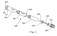
FIG. 1 is an exploded isometric view of a disposable cartridge for a hand-held, self-contained electrostatic spraying device; -
FIG. 2 is a cross-sectional view of the disposable cartridge withinFig 1 ; -
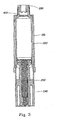
FIG. 3 is a cross-sectional view of a disposable cartridge having a static mixer; -
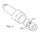
FIG. 4 is an isometric view of a disposable cartridge having at least one disc for increasing turbulent mixing; -
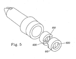
FIG. 5 is an isometric view of a disposable cartridge having at least one baffle for increasing turbulent mixing; - FIG. is a cross-sectional view of a disposable cartridge having a prop mixer;
-
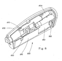
FIG. 7 is an exploded isometric view of a hand-held, self-contained electrostatic spraying device having a disposable cartridge; -
FIG. 8 is an assembled isometric view of the device withinFig 7 ; -
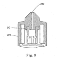
FIG. 9 is a cross-sectional view of the exiting portion of the device withinFig1 ; -
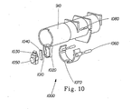
FIG. 10 is an exploded isometric view of the insert sleeve and accompanying parts withinFig. 1 ; and -
FIG. 11 is an isometric view of a disposable cartridge having a prop mixer which is unattached. - Referring to
Figures 7 and8 , a hand-held, self-containedelectrostatic spraying device 805 having adisposable cartridge 200 is shown.Disposable cartridge 200 may contain a variety of product, including but not limited to, cosmetics, skin creams, and skin lotions. The product indisposable cartridge 200 may be positively displaced (discussed infra) and powered by gearbox/motor component. Gearbox/motor component may be fixed onto a left orfirst housing 830. The gearbox/motor component can be affixed into place mechanically, adhesively, or by any other suitable technique. Gearbox/motor component preferably comprises a precision motor 810a connected to a gearbox810b. Power source 820 provides power to the device. An example of asuitable power source 820 includes, but is not limited to, two "AAA" type batteries. Thepower source 820 provides power to the device through thecontrol circuit 860 the highvoltage power supply 840, and then thehigh voltage contact 850, which contacts thedisposable cartridge 200. Highvoltage power supply 840 is powered and controlled by control circuit 860 (discussed infra). Power-onswitch 880 permits the user to cause an interruption betweenpower source 820 andcircuit control 860. Power-onswitch 880 is designed such that voltage is supplied to the remainder of the circuit only whenswitch 880 is in the "ON" or closed position. Applyswitch 870 permits the user to selectively activate motor 810a, thereby activating the delivery and spraying of the product. Gearbox/motor component has adriver 890 fastened to a shaft (not shown inFig 7 &8 , seeFig 1 ) ofgearbox 810b, for example, with a set screw (not shown).Driver 890 has a number of protruding fingers, for example, three, which can fit into the matching recesses on the back ofactuator 240. - Alternatively, the
product reservoir 220 may be formed of a conductive material and used to maintain the product reservoir at a high potential instead of having a separate conductive shield around thereservoir 220. Acartridge insulator 260 can prevent discharge from theconducive product reservoir 220 to points having a lower potential that are in close proximity to theproduct reservoir 220. Theproduct reservoir 220 can be molded of an electrically conductive material plastic such as acrylonitrile butadiene styrene (ABS) filled with 10% carbon fibers. Thecartridge insulator 260 provides an insulating cover to prevent discharge from theconductive product reservoir 220 to objects within the device having lower electrical potentials. In this embodiment, theconductive shield 210 is not required. - A first aspect of this invention relates to a means of mechanically mixing and re-suspending separated material within either
product reservoir 220 or within the subsequent product delivery pathway. In a first embodiment, as exampled inFigure 2 , one ormore mixing balls 290 are placed withinproduct reservoir 220.Disposable cartridge 200 is then shaken by the operator which causes mixingball 290 to move withinproduct reservoir 220. The movement of mixingball 290 withinproduct reservoir 220 achieves turbulent mixing of the product withinproduct reservoir 220, thereby reconstituting any separated product. It may be appreciated that the shaking ofdisposable cartridge 200 may occur while it is either inside or outside of the intended electrostatic spraying device. - In yet another embodiment that provides for product mixing, as exampled in
Figure 3 , astatic mixer 400 is placed in fluid communication betweenproduct reservoir 220 andnozzle exit orifice 280.Static mixer 400 is designed such that it creates a high degree of turbulent mixing within the fluid flow path in comparison to a straight fluid flow path. The turbulent mixing achieved within the fluid flow path should reconstitute any separated product.Static mixers 400 include, but are not limited to,: - 1. a helical type structure, as exampled in
Figure 3 , although other geometries may be appreciated; - 2. at least one
disc 500, as exampled inFigure 4 , having at least one hole 510.Disc 500 being inserted within the product flow path. A plurality ofdiscs 500 may be inserted, and more preferably with their holes 510 not being in axial alignment in order to increase turbulent mixing. It may be appreciated that one skilled in the art may change the diameter of holes 510, the location of holes 510, and/or the number of holes 510 in order to alter the degree of turbulent mixing. The diameter of hole 510 in the embodiment ofFigure 4 is approximately 0.030" diameter. - 3. at least one
baffle 600, as exampled inFigure 5 , having at least oneopening 610.Baffle 600 being inserted within the product flow path. A plurality ofbaffles 600 may be inserted, more preferably with theiropenings 610 not being in axial alignment in order to increase turbulent mixing. It may be appreciated that one skilled in the art may change the change the size ofbaffles 610, the location ofbaffles 610, and/or the number ofbaffles 610 in order to alter the degree of turbulent mixing. - In yet another embodiment, as exampled in
Figure 6 , aprop mixer 700 is added withinproduct reservoir 220 in order to provide product mixing.Prop mixer 700 may take the form of a paddle connected topiston 230. Aspiston 230 rotates up or down, so does propmixer 700, thereby creating turbulent mixing withinproduct reservoir 220. It may also be appreciated by one skilled in the art thatsuch prop mixer 700 need not necessarily be attached to apiston 230. Such alternative configurations include, but are not limited to: - 1. prop
mixer 700 being attached to another rotating member (e.g. threaded shaft 250) within either theproduct reservoir 220 or subsequent product delivery pathway; or - 2. prop
mixer 700 is unattached but yet still contained in said disposable so as to allowprop mixer 700 to rotate about a longitudinal axis to said disposable cartridge in response to product flow. - Yet another aspect of this invention relates to maintaining contact between
high voltage contact 850 andconductive shield 210 ondisposable cartridge 200. For the class of electrostatic spraying devices with removable/ replaceable product reservoirs, the ability to maintain the high voltage connection between the device itself and thedisposable cartridge 200 is paramount for maintaining a consistent, steady state spray. When interruptions exists in the connection between thehigh voltage contact 850 and conductive shield 210 (or any other similar electrodes), spraying is interrupted and/or an undesirable spray is produced. In one embodiment, as exampled inFigure 1 ,conductive shield 210 is of substantially circular geometry and has an annularelectrode contact portion 300. Annularelectrode contact portion 300 improves the intimate contact between thehigh voltage contact 850 andconductive shield 210 which is particularly important when theproduct reservoir 220 is rotated or moved withindevice 805. Such rotation and/or movement results in a period of interrupted supply of the high voltage power source, which leads to interruptions in spray performance. The addition of annularelectrode contact portion 300 helps to minimize this problem. In an alternative design (not shown), it may also be appreciated by one skilled in the art to construct thehigh voltage contact 850 in a substantially circular geometry in order to achieve similar results. One skilled in the art would appreciate the use of spring biasing to improve contact between thehigh voltage contact 850 andconductive shield 210, as exampled inFigure 7 . InFigure 7 ,high voltage contact 850 is configured as a 'leaf spring' such that when adisposable cartridge 200 is loaded intodevice 805, the leaf spring is biased to maintain contact withconductive shield 210. In yet another embodiment which improves the intimate contact between thehigh voltage contact 850 andconductive shield 210 is shown inFigures 9 and10 , further described below. - As exampled in
Figures 9 and10 , both locking and ejection features may be incorporated intodisposable cartridge 200 and sprayingdevice 805. In this embodiment, acatch mechanism 1020 is used to securedisposable cartridge 200 intoinsert sleeve 910 at aclasp location 1010.Catch mechanism 1020 also provides a positive tactile and audible signal to the user thatdisposable cartridge 200 is properly installed within device 5.Locking mechanism 1000 consists ofactuator button 1050, lockingslide 1030 and lockingspring 1040.Locking mechanism 1000 may be connected to the underside ofdisposable cartridge 200 or any other suitable location. Lockingslide 1030 is biased in the "UP" position by lockingspring 1040. When adisposable cartridge 200 is installed, lockingslide 1030 is moved down anddisposable cartridge 200 is placed withininsert sleeve 910. Whendisposable cartridge 200 is completely withininsert sleeve 910, lockingslide 1030 will slip into locking lug 310 (shown inFigure 1 ), thereby causing an audible click and securely locking disposable,cartridge 200 inside ofinsert sleeve 910.Actuator 240 moveselectrode cover 1070 in the same direction ofdisposable cartridge 200 insertion, thereby exposing high voltage contact 850 (not shown inFigure 10 ) inside of device 5.Electrode cover 1070 may be mounted within and guided back byslide channel 1080. While moving back,electrode cover 1070 compressesbias spring 1060. When a user desires to removedisposable cartridge 200 frominsert sleeve 910, the user actuatesactuator button 1050 to move lockingslide 1030 down, thereby disengaging it from lockinglug 310.Disposable cartridge 200 is then moved forward withininsert sleeve 910 by the decompression ofbias spring 1060. The user can then finish removingdisposable cartridge 200 fromdevice 805. Once installed and secured in place,locking mechanism 1000 will preventdisposable cartridge 200 from being inadvertently removed through shaking and handling ofdevice 805 during usage and storage. - Having shown and described the preferred embodiments of the present invention, further adaptions of the present invention as described herein can be accomplished by appropriate modifications by one of ordinary skill in the art without departing from the scope of the present invention. Several of these potential modifications and alternatives have been mentioned, and others will be apparent to those skilled in the art. For example, while exemplary embodiments of the present invention have been discussed for illustrative purposes, it should be understood that the elements described will be constantly updated and improved by technological advances. Accordingly, the scope of the present invention should be considered in terms of the following claims.
- Relevant electrostatic spray devices and cartridges are described in the following commonly-assigned, concurrently-filed U.S. Patent Applications:
- "Electrostatic Spray Device", which is published as
US 2001/020653 . - "Electrostatic Spray Device", which is published as
US 2001/038097 . - "Electrostatic Spray Device", which is published as
US 2001/020652 .
Claims (8)
- A cartridge (200) configured to contain and deliver a product for use with an electrostatic spray device characterized by:- a reservoir (220) configured to contain the product;- a nozzle to disperse the product, said nozzle having an exit orifice (280);- a channel disposed between said reservoir and said nozzle (280), wherein said channel permits the electrostatic charging of the product upon said product moving within said channel;- a high voltage contact (850) for receiving power from the electrostatic device;- a high voltage electrode electrically connected to said high voltage contact (850), said high voltage electrode being configured to charge the product in said channel;- a high voltage shield (210) substantially surrounding said reservoir, said high voltage shield being conductive;- a mixing mechanism (290; 400; 500, 510; 600) disposed between said reservoir (220) and said nozzle, said mixing mechanism being in fluid communication with the product, whereby said mixing mechanism reconstitutes the product.
- The cartridge of Claim 1, wherein said mixing mechanism is at least one mixing ball (290).
- The cartridge of Claim1, wherein said mixing mechanism is at least one static mixer (400).
- The cartridge of Claim 1, wherein said mixing mechanism is at least one disc (500) having at least one hole (510).
- The cartridge of Claim 4, wherein a plurality of said discs are arranged such that their respective holes are not axially aligned in order to increase turbulent mixing.
- The cartridge of Claim 4, wherein said hole has a diameter of approximately 0.030 inches.
- The cartridge of Claim 1, wherein said mixing mechanism is at least one baffle (600) having at least one opening.
- The cartridge of Claim 7, wherein a plurality of said baffles are arranged such that their respective opening are not axially aligned in order to increase turbulent mixing.
Applications Claiming Priority (3)
| Application Number | Priority Date | Filing Date | Title |
|---|---|---|---|
| US759549 | 2001-01-12 | ||
| US09/759,549 US6814318B2 (en) | 1999-08-18 | 2001-01-12 | Disposable cartridge for electrostatic spray device |
| PCT/US2002/000693 WO2002055209A2 (en) | 2001-01-12 | 2002-01-11 | Disposable cartridge for electrostatic spray device |
Publications (2)
| Publication Number | Publication Date |
|---|---|
| EP1349666A2 EP1349666A2 (en) | 2003-10-08 |
| EP1349666B1 true EP1349666B1 (en) | 2008-12-31 |
Family
ID=25056072
Family Applications (1)
| Application Number | Title | Priority Date | Filing Date |
|---|---|---|---|
| EP02707433A Expired - Lifetime EP1349666B1 (en) | 2001-01-12 | 2002-01-11 | Disposable cartridge for electrostatic spray device |
Country Status (11)
| Country | Link |
|---|---|
| US (1) | US6814318B2 (en) |
| EP (1) | EP1349666B1 (en) |
| JP (1) | JP2004517713A (en) |
| KR (1) | KR20030070104A (en) |
| CN (1) | CN1313213C (en) |
| AT (1) | ATE419069T1 (en) |
| CA (1) | CA2432226A1 (en) |
| CZ (1) | CZ20031494A3 (en) |
| DE (1) | DE60230582D1 (en) |
| MX (1) | MXPA03006256A (en) |
| WO (1) | WO2002055209A2 (en) |
Families Citing this family (20)
| Publication number | Priority date | Publication date | Assignee | Title |
|---|---|---|---|---|
| DE60320535T2 (en) * | 2002-02-25 | 2009-06-10 | The Procter & Gamble Company, Cincinnati | ELECTROSTATIC SPRAYER |
| US7841549B2 (en) * | 2004-02-09 | 2010-11-30 | Panasonic Electric Works Co., Ltd. | Electrostatic spraying device |
| WO2005075090A1 (en) * | 2004-02-09 | 2005-08-18 | Matsushita Electric Works, Ltd. | Electrostatic spraying device |
| EP1781414B1 (en) * | 2004-02-09 | 2008-11-12 | Matsushita Electric Works, Ltd | Electrostatic spraying device |
| US7867141B2 (en) * | 2004-07-21 | 2011-01-11 | Panasonic Electric Works Co., Ltd. | Physical activity measuring system |
| EP1848542A1 (en) | 2005-02-11 | 2007-10-31 | Battelle Memorial Institute | Ehd aerosol dispensing device and spraying method |
| EP1920581A4 (en) | 2006-09-01 | 2008-09-10 | Research In Motion Ltd | Integrated dialing |
| US8960575B2 (en) * | 2009-01-13 | 2015-02-24 | Finishing Brands Holdings Inc. | Electrostatic spray system and method |
| US8893990B2 (en) * | 2010-02-26 | 2014-11-25 | Finishing Brands Holdings Inc. | Electrostatic spray system |
| US8833679B2 (en) | 2010-11-24 | 2014-09-16 | Finishing Brands Holdings, Inc. | Electrostatic spray system with grounding teeth |
| JP6112130B2 (en) * | 2015-03-25 | 2017-04-12 | トヨタ自動車株式会社 | Electrostatic nozzle, discharge device, and method for manufacturing semiconductor module |
| FR3045298B1 (en) * | 2015-12-17 | 2018-01-26 | L'oreal | APPARATUS FOR TREATING HUMAN KERATINIC MATERIALS |
| FR3045289B1 (en) | 2015-12-17 | 2021-09-03 | Oreal | DEVICE FOR TREATMENT OF HUMAN KERATINIC MATERIALS, IN PARTICULAR USING AN ELECTRIC CURRENT |
| FR3045296B1 (en) | 2015-12-17 | 2018-01-26 | L'oreal | DEVICE FOR THE TREATMENT OF HUMAN KERATINIC MATERIALS, PARTICULARLY USING AN ELECTRICAL CURRENT |
| US10851475B2 (en) | 2017-11-21 | 2020-12-01 | Kao Corporation | Electrospinning apparatus and systems and methods thereof |
| TWI805687B (en) | 2018-02-08 | 2023-06-21 | 日商花王股份有限公司 | Composition for coating film formation |
| US11583487B2 (en) | 2018-08-09 | 2023-02-21 | Kao Corporation | Method for producing coating |
| USD925694S1 (en) | 2018-08-10 | 2021-07-20 | Kao Corporation | Cartridge for fluid emitting device |
| USD913420S1 (en) | 2018-08-10 | 2021-03-16 | Kao Corporation | Fluid emitting device |
| USD910808S1 (en) | 2018-08-10 | 2021-02-16 | Kao Corporation | Main body of fluid emitting device |
Family Cites Families (60)
| Publication number | Priority date | Publication date | Assignee | Title |
|---|---|---|---|---|
| US2159894A (en) | 1937-02-04 | 1939-05-23 | Posie L Hines | Sprayer |
| US2629516A (en) | 1951-10-02 | 1953-02-24 | Lucretia E Badham | Combination liquid pistol and spotlight |
| DE1050338B (en) | 1952-12-30 | |||
| FR2127433A5 (en) | 1971-03-01 | 1972-10-13 | Tech Cuir Centre | Electrostatic spraying process and machine - for finishing of leathers |
| GB1454395A (en) | 1973-07-26 | 1976-11-03 | Volstatic Coatings Ltd | Power supply voltage control circuit |
| US4122845A (en) | 1975-09-30 | 1978-10-31 | Bowles Fluidics Corporation | Personal care spray device |
| US4079894A (en) | 1976-07-14 | 1978-03-21 | Nordson Corporation | Electrostatic spray coating gun |
| US4194696A (en) | 1976-07-14 | 1980-03-25 | Nordson Corporation | Electrostatic spray coating gun |
| US4331298A (en) | 1977-03-02 | 1982-05-25 | Ransburg Corporation | Hand-held coating-dispensing apparatus |
| US4258073A (en) | 1978-03-02 | 1981-03-24 | Payne John M | Taking of finger prints |
| BE868443A (en) | 1978-06-26 | 1978-12-27 | Staar Dev Cy S A | SINGLE-DOSAGE PACKAGING / DISPENSER SYSTEM |
| SU867927A1 (en) | 1979-04-02 | 1981-09-30 | Орловский научно-исследовательский институт легкого машиностроения | Chamber for topping leather in electrostatic field |
| BE882450A (en) | 1980-03-26 | 1980-07-16 | Ransburg G M B H | DEVICE FOR ELECTROSTATIC DISPERSION IN A SHOWER OF COATING SUBSTANCE |
| BE882449A (en) | 1980-03-26 | 1980-07-16 | Ransburg Japan Ltd | ELECTROSTATIC COATING PROCESS AND ROTARY PAINT SPRAYING DEVICE FOR CARRYING OUT SAID METHOD |
| DE3174591D1 (en) | 1981-01-30 | 1986-06-12 | Ici Plc | Process of spraying emulsions and apparatus thereof |
| EP0096731A1 (en) | 1982-06-09 | 1983-12-28 | Gabriel Bernaz | Apparatus for aesthetic and electrotherapeutic care, and atomising device |
| GB2128900B (en) | 1982-10-29 | 1985-11-20 | Theoktiste Christofidis | Ionising spray |
| GB8305816D0 (en) | 1983-03-02 | 1983-04-07 | Ici Plc | Containers |
| EP0120633B1 (en) | 1983-03-25 | 1988-12-14 | Imperial Chemical Industries Plc | Spraying apparatus |
| US5229105A (en) | 1986-05-28 | 1993-07-20 | Donald Basiliere | Multi-active skin preparation |
| US4907727A (en) | 1988-10-31 | 1990-03-13 | Illinois Tool Works, Inc. | Dispensing device having improved plunger assemblies |
| US4971257A (en) * | 1989-11-27 | 1990-11-20 | Marc Birge | Electrostatic aerosol spray can assembly |
| US5105984A (en) | 1990-06-27 | 1992-04-21 | Kazimir Charles E | Paste tube dispenser and method for making same |
| ES2071927T3 (en) | 1990-07-25 | 1995-07-01 | Ici Plc | ELECTROSTATIC SPRAY METHOD. |
| DK0468736T3 (en) * | 1990-07-25 | 1997-09-01 | Ici Plc | Apparatus and method for electrostatic spraying. |
| GB9023339D0 (en) | 1990-10-26 | 1990-12-05 | Ici Plc | Dispensing of fluids |
| US5296681A (en) | 1991-01-15 | 1994-03-22 | Gunter Tschauder | Apparatus for hot moistening face-towels |
| GB9101812D0 (en) | 1991-01-28 | 1991-03-13 | Morgan Crucible Co | Dispensing of fluids |
| PT501725E (en) | 1991-03-01 | 2001-10-31 | Procter & Gamble | PULVERIZATION OF LIQUIDS |
| GB9115276D0 (en) | 1991-07-15 | 1991-08-28 | Unilever Plc | Skin treatment system |
| GB9115277D0 (en) | 1991-07-15 | 1991-08-28 | Unilever Plc | Spraying system |
| GB9115279D0 (en) | 1991-07-15 | 1991-08-28 | Unilever Plc | Hair and scalp treatment system |
| GB9115278D0 (en) | 1991-07-15 | 1991-08-28 | Unilever Plc | Liquid spraying apparatus and method |
| GB9115275D0 (en) | 1991-07-15 | 1991-08-28 | Unilever Plc | Colour cosmetic spray system |
| CA2076488A1 (en) | 1991-09-27 | 1993-03-28 | James A. Quinn | Continuous monitoring electrostatic discharge system |
| DE4138763A1 (en) | 1991-11-26 | 1993-05-27 | Basf Ag | USE OF HOMO- OR COPOLYMERISATS BASED ON QUATERNIZED 1-VINYLIMIDAZOLES AS ORGANIC POLYELECTROLYTE |
| US5531384A (en) | 1992-06-18 | 1996-07-02 | Greene; Robert H. | Spray gun |
| JP3100783B2 (en) | 1992-10-15 | 2000-10-23 | キユーピー株式会社 | Phosphatidylcholine and method for producing the same |
| GB9224191D0 (en) | 1992-11-18 | 1993-01-06 | Unilever Plc | Cosmetic delivery system |
| CA2149861C (en) | 1992-11-23 | 2001-06-12 | Louis L. Punto | Self-tanning cosmetic compositions and methods of using the same |
| GB2273872A (en) | 1992-12-22 | 1994-07-06 | Unilever Plc | A method of treating skin |
| GB2273673A (en) | 1992-12-22 | 1994-06-29 | Unilever Plc | Dental active delivery system |
| DE4312262A1 (en) * | 1993-04-15 | 1994-10-20 | Gema Volstatic Ag | Electrostatic spray device |
| WO1994027560A1 (en) | 1993-05-26 | 1994-12-08 | The Procter & Gamble Company | Solid cosmetics having moisturizing effect |
| US5674481A (en) | 1993-06-24 | 1997-10-07 | Wahi; Ashok L. | Electrostatically charged nasal topical application product |
| US5468488A (en) | 1993-06-24 | 1995-11-21 | Wahi; Ashok L. | Electrostatically charged nasal application product and method |
| JP3686675B2 (en) * | 1993-11-16 | 2005-08-24 | ザ プロクター アンド ギャンブル カンパニー | Electrostatic spraying equipment |
| JP3403199B2 (en) | 1994-04-29 | 2003-05-06 | ザ プラクター アンド ギャムブル カンパニー | Spraying equipment |
| CH688080A5 (en) | 1994-09-29 | 1997-05-15 | Kwc Ag | Shower with a handle and a actuated by a hand lever shutoff. |
| GB9511514D0 (en) | 1995-06-07 | 1995-08-02 | Ici Plc | Electrostatic spraying |
| GB9420511D0 (en) | 1994-10-11 | 1994-11-23 | Ici Plc | High voltage generator |
| PL179126B1 (en) | 1994-10-04 | 2000-07-31 | Procter & Gamble | Method of and apparatus for electrostatically atomising solid particles |
| WO1997033527A1 (en) | 1996-03-11 | 1997-09-18 | The Procter & Gamble Company | Electrostatic hand sanitizer |
| US6079634A (en) * | 1996-05-30 | 2000-06-27 | The Procter & Gamble Company | Electrostatic spraying |
| GB9622623D0 (en) | 1996-10-30 | 1997-01-08 | Ici Plc | Dispensing devices |
| JPH10146216A (en) | 1996-11-18 | 1998-06-02 | Shiseido Co Ltd | Applying tool for makeup |
| EP0941145B1 (en) * | 1996-12-06 | 2002-09-18 | ABB Research Ltd. | Powder spraying device |
| US6682004B2 (en) | 1999-08-18 | 2004-01-27 | The Procter & Gamble Company | Electrostatic spray device |
| US7712687B2 (en) | 1999-08-18 | 2010-05-11 | The Procter & Gamble Company | Electrostatic spray device |
| US6638233B2 (en) | 1999-08-19 | 2003-10-28 | Fox Hollow Technologies, Inc. | Apparatus and methods for material capture and removal |
-
2001
- 2001-01-12 US US09/759,549 patent/US6814318B2/en not_active Expired - Lifetime
-
2002
- 2002-01-11 KR KR10-2003-7009346A patent/KR20030070104A/en not_active Ceased
- 2002-01-11 CA CA002432226A patent/CA2432226A1/en not_active Abandoned
- 2002-01-11 CZ CZ20031494A patent/CZ20031494A3/en unknown
- 2002-01-11 DE DE60230582T patent/DE60230582D1/en not_active Expired - Fee Related
- 2002-01-11 MX MXPA03006256A patent/MXPA03006256A/en unknown
- 2002-01-11 JP JP2002555931A patent/JP2004517713A/en active Pending
- 2002-01-11 AT AT02707433T patent/ATE419069T1/en not_active IP Right Cessation
- 2002-01-11 WO PCT/US2002/000693 patent/WO2002055209A2/en not_active Ceased
- 2002-01-11 CN CNB028035488A patent/CN1313213C/en not_active Expired - Lifetime
- 2002-01-11 EP EP02707433A patent/EP1349666B1/en not_active Expired - Lifetime
Also Published As
| Publication number | Publication date |
|---|---|
| EP1349666A2 (en) | 2003-10-08 |
| CN1484548A (en) | 2004-03-24 |
| KR20030070104A (en) | 2003-08-27 |
| JP2004517713A (en) | 2004-06-17 |
| ATE419069T1 (en) | 2009-01-15 |
| US20010023902A1 (en) | 2001-09-27 |
| CN1313213C (en) | 2007-05-02 |
| CZ20031494A3 (en) | 2003-11-12 |
| US6814318B2 (en) | 2004-11-09 |
| WO2002055209A2 (en) | 2002-07-18 |
| MXPA03006256A (en) | 2003-09-22 |
| WO2002055209A3 (en) | 2003-02-27 |
| DE60230582D1 (en) | 2009-02-12 |
| CA2432226A1 (en) | 2002-07-18 |
Similar Documents
| Publication | Publication Date | Title |
|---|---|---|
| US6814318B2 (en) | Disposable cartridge for electrostatic spray device | |
| US7152817B2 (en) | Electrostatic spray device | |
| US6216966B1 (en) | Dispensing devices | |
| JP6196223B2 (en) | Electrostatic fluid distributor without using VOC | |
| KR100484360B1 (en) | Disposable cartridge for use in a hand-held electrostatic sprayer apparatus | |
| JP2003507166A (en) | Hand-held electrostatic spray device | |
| KR20180078281A (en) | Aseptic aerosol misting device | |
| AU2438492A (en) | Spray gun | |
| EP2070839B1 (en) | Lead screw locking device for handheld electrostatic atomizing device | |
| KR100386386B1 (en) | Actuators for Electrostatically Charged Aerosol Spray Systems | |
| JP7394595B2 (en) | electrostatic spray device | |
| DE3202597A1 (en) | Device for atomising fluids | |
| AU2002241841A1 (en) | Disposable cartridge for electrostatic spray device | |
| KR20180077240A (en) | Aseptic aerosol misting device | |
| US11678739B1 (en) | Vibrating soap or lotion dispensing bath brush | |
| AU2002241842A1 (en) | Electrostatic spray device | |
| WO2023171764A1 (en) | Electrostatic spraying device |
Legal Events
| Date | Code | Title | Description |
|---|---|---|---|
| PUAI | Public reference made under article 153(3) epc to a published international application that has entered the european phase |
Free format text: ORIGINAL CODE: 0009012 |
|
| 17P | Request for examination filed |
Effective date: 20030718 |
|
| AK | Designated contracting states |
Kind code of ref document: A2 Designated state(s): AT BE CH CY DE DK ES FI FR GB GR IE IT LI LU MC NL PT SE TR |
|
| AX | Request for extension of the european patent |
Extension state: AL LT LV MK RO SI |
|
| 17Q | First examination report despatched |
Effective date: 20070724 |
|
| GRAP | Despatch of communication of intention to grant a patent |
Free format text: ORIGINAL CODE: EPIDOSNIGR1 |
|
| GRAS | Grant fee paid |
Free format text: ORIGINAL CODE: EPIDOSNIGR3 |
|
| GRAA | (expected) grant |
Free format text: ORIGINAL CODE: 0009210 |
|
| AK | Designated contracting states |
Kind code of ref document: B1 Designated state(s): AT BE CH CY DE DK ES FI FR GB GR IE IT LI LU MC NL PT SE TR |
|
| REG | Reference to a national code |
Ref country code: GB Ref legal event code: FG4D Ref country code: CH Ref legal event code: EP |
|
| REF | Corresponds to: |
Ref document number: 60230582 Country of ref document: DE Date of ref document: 20090212 Kind code of ref document: P |
|
| REG | Reference to a national code |
Ref country code: IE Ref legal event code: FG4D |
|
| PG25 | Lapsed in a contracting state [announced via postgrant information from national office to epo] |
Ref country code: FI Free format text: LAPSE BECAUSE OF FAILURE TO SUBMIT A TRANSLATION OF THE DESCRIPTION OR TO PAY THE FEE WITHIN THE PRESCRIBED TIME-LIMIT Effective date: 20081231 Ref country code: NL Free format text: LAPSE BECAUSE OF FAILURE TO SUBMIT A TRANSLATION OF THE DESCRIPTION OR TO PAY THE FEE WITHIN THE PRESCRIBED TIME-LIMIT Effective date: 20081231 |
|
| NLV1 | Nl: lapsed or annulled due to failure to fulfill the requirements of art. 29p and 29m of the patents act | ||
| PG25 | Lapsed in a contracting state [announced via postgrant information from national office to epo] |
Ref country code: BE Free format text: LAPSE BECAUSE OF FAILURE TO SUBMIT A TRANSLATION OF THE DESCRIPTION OR TO PAY THE FEE WITHIN THE PRESCRIBED TIME-LIMIT Effective date: 20081231 Ref country code: ES Free format text: LAPSE BECAUSE OF FAILURE TO SUBMIT A TRANSLATION OF THE DESCRIPTION OR TO PAY THE FEE WITHIN THE PRESCRIBED TIME-LIMIT Effective date: 20090411 |
|
| PG25 | Lapsed in a contracting state [announced via postgrant information from national office to epo] |
Ref country code: MC Free format text: LAPSE BECAUSE OF NON-PAYMENT OF DUE FEES Effective date: 20090131 Ref country code: AT Free format text: LAPSE BECAUSE OF FAILURE TO SUBMIT A TRANSLATION OF THE DESCRIPTION OR TO PAY THE FEE WITHIN THE PRESCRIBED TIME-LIMIT Effective date: 20081231 Ref country code: PT Free format text: LAPSE BECAUSE OF FAILURE TO SUBMIT A TRANSLATION OF THE DESCRIPTION OR TO PAY THE FEE WITHIN THE PRESCRIBED TIME-LIMIT Effective date: 20090601 Ref country code: SE Free format text: LAPSE BECAUSE OF FAILURE TO SUBMIT A TRANSLATION OF THE DESCRIPTION OR TO PAY THE FEE WITHIN THE PRESCRIBED TIME-LIMIT Effective date: 20090331 |
|
| REG | Reference to a national code |
Ref country code: CH Ref legal event code: PL |
|
| REG | Reference to a national code |
Ref country code: IE Ref legal event code: MM4A |
|
| PG25 | Lapsed in a contracting state [announced via postgrant information from national office to epo] |
Ref country code: CH Free format text: LAPSE BECAUSE OF NON-PAYMENT OF DUE FEES Effective date: 20090131 Ref country code: DK Free format text: LAPSE BECAUSE OF FAILURE TO SUBMIT A TRANSLATION OF THE DESCRIPTION OR TO PAY THE FEE WITHIN THE PRESCRIBED TIME-LIMIT Effective date: 20081231 Ref country code: LI Free format text: LAPSE BECAUSE OF NON-PAYMENT OF DUE FEES Effective date: 20090131 Ref country code: DE Free format text: LAPSE BECAUSE OF NON-PAYMENT OF DUE FEES Effective date: 20090801 |
|
| PLBE | No opposition filed within time limit |
Free format text: ORIGINAL CODE: 0009261 |
|
| STAA | Information on the status of an ep patent application or granted ep patent |
Free format text: STATUS: NO OPPOSITION FILED WITHIN TIME LIMIT |
|
| REG | Reference to a national code |
Ref country code: FR Ref legal event code: ST Effective date: 20091030 |
|
| 26N | No opposition filed |
Effective date: 20091001 |
|
| PG25 | Lapsed in a contracting state [announced via postgrant information from national office to epo] |
Ref country code: IE Free format text: LAPSE BECAUSE OF NON-PAYMENT OF DUE FEES Effective date: 20090111 |
|
| PG25 | Lapsed in a contracting state [announced via postgrant information from national office to epo] |
Ref country code: FR Free format text: LAPSE BECAUSE OF NON-PAYMENT OF DUE FEES Effective date: 20090302 |
|
| PG25 | Lapsed in a contracting state [announced via postgrant information from national office to epo] |
Ref country code: GR Free format text: LAPSE BECAUSE OF FAILURE TO SUBMIT A TRANSLATION OF THE DESCRIPTION OR TO PAY THE FEE WITHIN THE PRESCRIBED TIME-LIMIT Effective date: 20090401 |
|
| PG25 | Lapsed in a contracting state [announced via postgrant information from national office to epo] |
Ref country code: IT Free format text: LAPSE BECAUSE OF FAILURE TO SUBMIT A TRANSLATION OF THE DESCRIPTION OR TO PAY THE FEE WITHIN THE PRESCRIBED TIME-LIMIT Effective date: 20081231 |
|
| PG25 | Lapsed in a contracting state [announced via postgrant information from national office to epo] |
Ref country code: LU Free format text: LAPSE BECAUSE OF NON-PAYMENT OF DUE FEES Effective date: 20090111 |
|
| PG25 | Lapsed in a contracting state [announced via postgrant information from national office to epo] |
Ref country code: TR Free format text: LAPSE BECAUSE OF FAILURE TO SUBMIT A TRANSLATION OF THE DESCRIPTION OR TO PAY THE FEE WITHIN THE PRESCRIBED TIME-LIMIT Effective date: 20081231 |
|
| PG25 | Lapsed in a contracting state [announced via postgrant information from national office to epo] |
Ref country code: CY Free format text: LAPSE BECAUSE OF FAILURE TO SUBMIT A TRANSLATION OF THE DESCRIPTION OR TO PAY THE FEE WITHIN THE PRESCRIBED TIME-LIMIT Effective date: 20081231 |
|
| PGFP | Annual fee paid to national office [announced via postgrant information from national office to epo] |
Ref country code: GB Payment date: 20201230 Year of fee payment: 20 |
|
| REG | Reference to a national code |
Ref country code: GB Ref legal event code: PE20 Expiry date: 20220110 |
|
| PG25 | Lapsed in a contracting state [announced via postgrant information from national office to epo] |
Ref country code: GB Free format text: LAPSE BECAUSE OF EXPIRATION OF PROTECTION Effective date: 20220110 |