EP1349373A2 - Method of correcting color image data according to correction table - Google Patents
Method of correcting color image data according to correction table Download PDFInfo
- Publication number
- EP1349373A2 EP1349373A2 EP03005852A EP03005852A EP1349373A2 EP 1349373 A2 EP1349373 A2 EP 1349373A2 EP 03005852 A EP03005852 A EP 03005852A EP 03005852 A EP03005852 A EP 03005852A EP 1349373 A2 EP1349373 A2 EP 1349373A2
- Authority
- EP
- European Patent Office
- Prior art keywords
- image data
- lattice points
- value
- color image
- lattice
- Prior art date
- Legal status (The legal status is an assumption and is not a legal conclusion. Google has not performed a legal analysis and makes no representation as to the accuracy of the status listed.)
- Withdrawn
Links
Images










Classifications
-
- H—ELECTRICITY
- H04—ELECTRIC COMMUNICATION TECHNIQUE
- H04N—PICTORIAL COMMUNICATION, e.g. TELEVISION
- H04N1/00—Scanning, transmission or reproduction of documents or the like, e.g. facsimile transmission; Details thereof
- H04N1/46—Colour picture communication systems
- H04N1/56—Processing of colour picture signals
- H04N1/60—Colour correction or control
- H04N1/6016—Conversion to subtractive colour signals
- H04N1/6019—Conversion to subtractive colour signals using look-up tables
Definitions
- the process of forcibly allocating the coordinate point corresponding to target color image data to the peripheral lattice point prior to referring to the color correction table is called the 'prior art pre-conversion process'.
- the corrected color image data obtained from the lattice points allocated by the prior art pre-conversion process is different from the original corrected color image data obtained by direct color correction of the target color image data.
- the error arising due to pre-conversion is called the 'pre-conversion error'.
- the preferable procedure of pre-conversion enables the pre-conversion errors arising in the individual color image data to be mutually cancelled and makes the total error in a predetermined image area within an allowable level. This desirably prevents the image quality from being worsened by the pre-conversion error.
- the procedure receives the target color image data expressed by the coordinate value in the color space and selects N (where N is an integer of not less than 2) lattice points in an undefined manner among lattice points that have distances of not longer than a preset value from the coordinate value of the target color image data.
- N is an integer of not less than 2
- lattice points in an undefined manner means that the selected lattice points are not fixed to the target color image data. Namely different lattice points may be selected every time for the identical target color image data.
- the selection in the undefined manner includes selection in a probabilistic manner or a stochastic manner.
- the procedure specifies the corrected color image data corresponding to the target color image data, based on the corrected data stored at the selected N lattice points.
- the selected lattice points are not fixed according to the coordinate value of the target color image data, but the N lattice points are selected in an undefined manner.
- the technique of undefined selection allows to adopt a simple method and ensures the higher-speed selection of the multiple lattice points, compared with the technique of defined selection according to the coordinate value of the target color image data, thus enabling the target color image data to be corrected at a higher speed.
- the N lattice points are selected in an undefined manner.
- the technique of undefined selection ensures the higher-speed selection of the multiple lattice points, compared with the technique of defined selection.
- the corrected data specification module reads the corrected data stored at the selected N lattice points from the correction table and calculates an arithmetic mean of the corrected data read from the selected N lattice points, so as to specify corrected color image data corresponding to the target color image data.
- the conventional interpolation technique specifies adequate weight coefficients according to the positional relationship between the coordinate value of the target color image data and respective lattice points and multiplies the corrected data stored at the respective lattice points by the specified weight coefficients.
- the arrangement of the invention does not require such multiplication and thereby ensures the higher-speed processing than the interpolation technique.
- the arrangement specifies the arithmetic mean of the corrected data read from the multiple lattice points as the corrected color image data corresponding to the target color image data.
- the third application of the image processing apparatus and the image processing method of the invention desirably reduce the pre-conversion error and ensure quick output of a high-quality resulting image without increasing the storage capacity required for the correction table.
- the noise is selectable from a predetermined range.
- the threshold value is determined in advance to allow for mutual cancellation of the differences between the respective noises and the threshold value and to cause the total difference to be not greater than an allowable level.
- the multiple lattice points are selected, based on the result of comparison between the decision data and the predetermined threshold value. This arrangement effectively restricts the total correction error arising in the process of correcting a large number of target color image data to be not greater than a preset level and thereby ensures output of a high-quality resulting image.
- one preferable procedure selects two lattice points for the target color image data and specifies the corrected color image data corresponding to the target color image data based on the corrected data read from the selected two lattice points.
- the arrangement of selecting two lattice points for the target color image data and specifying the corrected color image data effectively reduces the pre-conversion error as discussed later in detail.
- This arrangement desirably decreases the pre-conversion error and ensures output of a high-quality resulting image without increasing the storage capacity required for the correction table.
- the general bit shifting operation in the computer can be used to implement the quick calculation of the arithmetic mean and thereby ensure high-speed correction of the target color image data.
- An adequate number of lattice points may be selected for the target color image data according to image processing conditions.
- the procedure may detect setting of a processing mode, which gives a priority to at least either of an execution speed of the preset series of correction and a correction accuracy of the target color image data, and select a specified number of the lattice points according to the detected processing mode.
- the execution speed of the preset series of correction or the correction accuracy of the target color image data may be set in an explicit manner or may be specified based on the settings of the image processing conditions.
- One preferable arrangement of the above application selects a greater number of the lattice points in a certain setting of the processing mode that gives the priority to the correction accuracy over the execution speed than a number of lattice points in another setting of the processing mode that gives the priority to the execution speed over the correction accuracy.
- the target color image data may be RGB image data expressed by coordinate values in a color space defined by a red (R) axis, a green (G) axis, and a blue (B) axis.
- the correction table may store tone values of at least cyan, magenta, and yellow as the corrected data.
- the computer program causes a computer to attain the functions of: (A) storing corrected data, which is expressed by a coordinate value, at each of lattice points defined by division of the color space with regard to each dimension; (B) selecting N (where N is an integer of not less than 2) lattice points in an overlap-allowable manner among lattice points that have distances of not longer than a preset value from the coordinate value of the target color image data; and (C) specifying corrected color image data corresponding to the target color image data, based on the corrected data stored at the selected N lattice points.
- the function (B) selects the N lattice points in an undefined manner.
- the function (B) when the target color image data is expressed by a coordinate value in an M-dimensional color space (where M is an arbitrary positive integer), selects multiple but not greater than M lattice points as the N lattice points.
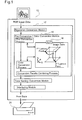
- the pre-conversion / color conversion module 14 sequentially carries out a pre-conversion process, a color conversion process, and a conversion results combining process with regard to the RGB image data transmitted from the resolution conversion module.
- the color conversion process refers to a color conversion look-up table LUT 16 to convert image data expressed by tone values of respective R, G, and B colors into image data expressed by tone values of colors printable by the color printer 20, that is, cyan (C), magenta (M), and yellow (Y).
- the color conversion table LUT 16 stores tone values of the CMY colors mapped to the RGB image data at respective lattice points, which are defined by dividing an RGB color space into lattices.
- the following description is on the assumption that the color printer 20 uses inks of only the C, M, and Y colors.
- the explanation is, however, applicable to any color printer with additional color inks, for example, black (K), light cyan (LC), and light magenta (LM).
- the coordinate point of the image data is allocated to the two lattice points in the illustrated example.
- the number of the lattice points to be allocated is not restricted to 2, but the coordinate point may be allocated to a greater number of lattice points.
- the coordinate point may be allocated to one identical lattice point in an overlapping manner. Namely the first lattice point and the second lattice point in the illustrated example may be an identical lattice point.
- the pre-conversion process generates multiple lattice points from one coordinate point of the color image data.
- the subsequent color conversion process refers to the color conversion table LUT to convert RGB color image data at the respective lattice points into CYM color image data.
- tetrahedral interpolation which has the less number of lattice points to be referred to, among various interpolation techniques should refer to data at four lattice points.
- the procedure of the present invention should refer to data at only two lattice points for color conversion.
- the pre-conversion error arising by the procedure of the present invention is greater than the pre-conversion error arising by the prior art interpolation technique, the pre-conversion error within the allowable range does not significantly affect the picture quality. In most cases, referring to data at only two lattice points sufficiently reduces the pre-conversion error.
- a second application of the present invention selects M or less multiple lattice points in the LUT in the vicinity of each coordinate point of M-dimensional color image data and allocates the coordinate point of the M-dimensional color image data to the selected multiple lattice points.
- the procedure then reads the CMY image data stored at the multiple lattice points and calculates the CMY image data corresponding to the RGB image data, based on the CMY image data read from the lattice points. Because of the similar reason to that discussed in the first application of the present invention, this arrangement desirably reduces the pre-conversion error, compared with the prior art pre-conversion technique that allocates one coordinate point to one lattice point.
- the number of lattice points, to which the M-dimensional image data is allocated is not greater than M. This ensures the higher-speed color conversion.
- the prior art interpolation method should refer to at least (M+1) lattice points for color conversion of the M-dimensional image data. Compared with this prior art method, the pre-conversion / color conversion process of the second application according to the present invention significantly shortens the total time required for color conversion.
- a third application of the present invention reads the CMY image data from multiple lattice points, to which the image data is allocated, calculates an arithmetic mean of the CMY image data read from the multiple lattice points, and calculates CMY image data corresponding to the RGB image data based on the calculated arithmetic mean. Because of the similar reason to that discussed in the first application of the present invention, the process of color conversion of the RGB image data based on the arithmetic mean of the CMY image data read from the multiple lattice points, to which one coordinate point is allocated, desirably reduces the pre-conversion error, compared with the prior art pre-conversion technique.
- Fig. 2(b) shows a process of allocating image data to two lattice points. Allocation of image data to a greater number of lattice points is allowable. This arrangement will be discussed later as a modified example.
- the two lattice points, to which the image data is allocated are differentiated as a first lattice point and a second lattice point.
- the image data may be allocated to the one identical lattice point P1 in an overlapping manner or may alternatively be allocated to the two lattice points P1 and P2.
- the tone value C1 is obtained from both of the first lattice point and the second lattice point.
- the tone value of the color-converted image data is accordingly equal to the tone value C1 as the arithmetic mean of the obtained tone values.
- the arithmetic mean is not restrictive at all, but the tone value of the color-converted image data may be equal to an internally dividing point of the obtained tone values at an arbitrary ratio.
- a pre-conversion error equal to a tone value difference (Cx - C1), where Cx denotes a tone value of color-converted image data obtained without pre-conversion (for example, by the known interpolation method).
- Cx denotes a tone value of color-converted image data obtained without pre-conversion (for example, by the known interpolation method).
- the pre-conversion error is maximized in the case of allocation of the image data to the identical lattice point P1 as both of the first lattice point and the second lattice point, when the image data has an intermediate tone value between the tone values of the lattice points P1 and P2.
- This error is equal to an error arising due to allocation of the image data corresponding to the midpoint of the lattice points P1 and P2 to the lattice point P1 in the prior art pre-conversion technique shown in Fig. 2(a).
- the maximum pre-conversion error is thus significantly reduced.
- 3(a) is obtained by dividing the range from the tone value R1 to the tone value R2 into 50 equal parts, carrying out pre-conversion of image data corresponding to respective divisional points multiple times (about thousand times), and connecting calculated standard deviations of pre-conversion errors at the respective divisional points.
- the prior art pre-conversion technique that allocates one image data to one lattice point gives the maximum pre-conversion error by allocation of the image data equivalent to the lattice point P2 to the lattice point P1.
- the pre-conversion process of the present invention that allocates one image data to two lattice points significantly reduces the maximum pre-conversion error.
- Several methods are applicable for allocation of one image data to two lattice points. These methods will be described later in detail as embodiments of the present invention.
- the tone value C1 is read from the first lattice point and the tone value C4 is read from the second lattice point.
- the resulting tone value of the color-converted image data is the arithmetic mean of these tone values, that is, a tone value (C1+C4)/2.
- This calculated tone value is substantially equivalent to the tone value obtained by color conversion of image data at the midpoint between the lattice points P1 and P4.
- the procedure of the modified example specifies a lattice point having defined tone values of the respective components as the first lattice point and a lattice point having undefined tone values of the respective components as the second lattice point.
- the tone value R1 of the R component and the tone value G2 of the G component are defined.
- the first lattice point is accordingly allocated to the lattice point P3 having the coordinate values (R1,G2), which are the combination of the defined tone values of the respective components.
- the arrow of solid line extending from the symbol ' ⁇ ' representing the coordinate point of the image data to the lattice point P3 in Fig. 5(a) schematically shows allocation of the first lattice point to the lattice point P3.
- An ink cartridge 242 where the K ink is kept and an ink cartridge 243 where the C ink, the M ink, and the Y ink are kept are attached to the carriage 240. Attachment of the ink cartridges 242 and 243 to the carriage 240 causes the respective color inks in the ink cartridges 242 and 243 to be led to ink ejection heads 244 through 247 of the respective colors disposed below the print head 241 via ink conduits (not shown) and to be ejected from the corresponding ink ejection heads 244 through 247 in the form of ink droplets.
- the control circuit 260 includes a CPU 261, a ROM 262, and a RAM 263.
- the control circuit 260 controls the operations of the carriage motor 230 and the sheet feed motor 235 to regulate main scans and sub-scans of the carriage 240 and to make ink droplets ejected from respective nozzles at adequate timings based on the print data supplied from the computer 100. Under the control of the control circuit 260, ink dots of the respective colors are created at adequate positions on the printing paper P.
- the color printer 200 prints color images based on this principle.
- the image data have already been converted into the data of the lattice points in the LUT in the pre-conversion process.
- the color conversion process of the embodiment is thus required to simply read the data stored at the lattice points.
- the pre-conversion process of the embodiment converts one image data into data of multiple lattice points.
- the color conversion process of the embodiment accordingly reads the data of the multiple lattice points and calculates color-converted image data based on the data of the multiple lattice points. Both the process of reading the data stored at the lattice points and the process of calculating the color-converted image data based on the read data are implemented quickly.
- the color conversion process of the embodiment implements the processing at an extremely higher speed. The details of the color conversion process of the embodiment will be discussed later.
- the printer driver 12 carries out a tone number conversion process subsequent to the color conversion process (step S106).
- the RGB image data have been converted to the tone data of the C, M, Y, and K colors by the color conversion process.
- the tone data of each color has a range of 256 tones, that is, from a tone value 0 to a tone value 255.
- the color printer 200 of the embodiment is, however, capable of taking only either one of the two states 'dot creation state' and 'dot non-creation state'. It is accordingly required to convert the tone data of each color having the range of 256 tones into image data of 2 tones expressible by the color printer 200. Such conversion of the tone number is called the tone number conversion process.
- the printer driver 12 carries out an interlacing process (step S108).
- the interlacing process rearranges the image data of 2 tones corresponding to the dot creation state and the dot non-creation state in a specific order to be transferred to the color printer 200 by taking into account the order of dot creation.
- the printer driver 12 outputs the resulting image data, which have undergone the interlacing process, as print data to the color printer 200 (step S110).
- the color printer 200 creates ink dots of the respective colors on a printing medium according to the print data, thus printing a color image corresponding to the image data on the printing medium.
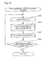
- Fig. 10 is a flowchart showing the pre-conversion / color conversion process of the first embodiment. This routine is executed by the printer driver 12 that utilizes the functions of the CPU 102 in the computer 100.
- the procedure After allocation of the image data to the first lattice point and the second lattice point, the procedure reads the tone values of the C, M, and Y colors stored at the first lattice point and the second lattice point in the LUT, thereby implementing color conversion of the RGB image data into the CMY image data (step S204). The details of this process will be discussed later.
- step S206 It is then determined whether or not the processing has been completed with regard to all the input RGB image data (step S206). When there is any non-converted RGB image data, the program returns to step S200 to carry out the series of processing. When all the RGB image data have been converted to the CMY image data, the program exits from the pre-conversion / color conversion process shown in the flowchart of Fig. 10 and returns to the image data conversion routine shown in the flowchart of Fig. 9.
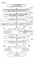
- Fig. 11 is a flowchart showing the process of allocating the image data to the lattice points (the pre-conversion process) in the pre-conversion / color conversion process.
- the processing at step S202 in the flowchart of Fig. 10 is described in detail with reference to the flowchart of Fig. 11.
- the printer driver 12 first detects the coordinate values of each lattice point in the vicinity of target image data Dx on the color space (step S300).
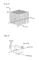
- Fig. 12 shows division of the color space into multiple small cubes or rectangular parallelepipeds by separation of the R, G, and B axes by multiple coordinate values.
- the LUT color conversion table
- the LUT is a numerical table including the tone values of the C, M, and Y colors mapped to the coordinate values of the lattice points and stored at the respective lattice points obtained by such division of the color space.
- a coordinate point corresponding to the input target RGB image data Dx is included in one of the multiple rectangular parallelepipeds in the RGB color space.
- Fig. 13 shows a coordinate point corresponding to the target image data Dx included in one specific rectangular parallelepiped.
- the specific rectangular parallelepiped is defined by dividing the RGB color space by tone values R1 and R2 on the axis R, by tone values G1 and G2 on the axis G, and by tone values B1 an B2 on the axis B.
- the target image data Dx is included in the range of the tone values R1 and R2.
- the target image data Dx is included in the range of the tone values G1 and G2.
- the target image data Dx is included in the range of the tone values B1 and B2.
- step S300 detects the coordinate values of the respective color components at the lattice points including the image data Dx (that is, the coordinate values of the adjoining lattice points on both sides of the target image data Dx with regard to each color component).
- the following description mainly regards the R component, since the respective color components R, G, and B are subjected to practically the same series of processing.
- the program After detecting the coordinate values including the target image data Dx (that is, the coordinate values of the adjoining lattice points on both sides of the target image data Dx) with regard to each component, the program calculates the interval of the coordinate values and generates a first noise Ns1 (step S302).
- This processing is discussed with an example of the component R.
- the target image data Dx is included in the range of the tone values R1 and R2, and the interval of the coordinate values is equal to a tone value (R2-R1).
- the generated first noise Ns1 has an amplitude that is half the interval of the coordinate values.
- the first noise Ns1 is calculated with regard to each of the R, G, and B color components, while the random digit generated by the function RD[0,1] may be an identical value for all the components R, G, and B.
- the first noise Ns1 may thus have an identical setting for all the components R, G, and B. Sharing the identical random digit and the identical setting of the first noise Ns1 desirably reduces the total processing time.
- the program subsequently sets an upper coordinate value Gup (the coordinate value corresponding to the greater tone value between the coordinate values of the adjoining lattice points on both sides of the target image data Dx) to a threshold value th (step S306), and compares the calculated first decision data Dr1 with the setting of the threshold value th with regard to each component (step S308).
- the upper coordinate value Gup is set to a coordinate value Pre1 of the first lattice point with regard to the certain component (step S310).
- a lower coordinate value Glw (the coordinate value corresponding to the smaller tone value between the coordinate values of the adjoining lattice points on both sides of the target image data Dx) is set to the coordinate value Pre1 of the first lattice point with regard to the certain component (step S312).
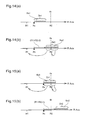
- Fig. 14(a) shows a process of setting the tone value of the first lattice point with regard to the component R.
- the symbol 'closed triangle' represents the position of the R component Rx of the image data Dx.
- the upper coordinate value Gup and the lower coordinate value Glw adjoining to the image data Dx are respectively equal to the tone value R2 and the tone value R1.
- the first noise Ns1 takes an arbitrary tone value in the range from the tone value '0' to the tone value (R2-R1)/2.
- the first decision data Dr1 obtained by adding the first noise Ns1 to the R component Rx of the image data Dx accordingly takes an arbitrary value in a hatched range shown in Fig. 14(a).
- the threshold value th is set equal to the tone value R2.
- the first decision data Dr1 does not exceed the threshold value th.
- the lower coordinate value Glw (the tone value R1) is always set to the R component of the first lattice point.
- the arrow of broken line extending from the hatched range to the coordinate value R1 in Fig. 14(b) schematically shows the fixed setting of the tone value R1 to the R component of the first lattice point, regardless of the setting of the first decision data Dr1.
- Fig. 15(a) shows a process of setting the R component of the first lattice point when the R component Rx of the target image data Dx is greater than the mean value of the two adjoining coordinate values R1 and R2.
- the first decision data Dr1 obtained by adding the first noise Ns1 to the R component Rx of the image data Dx takes an arbitrary value in a hatched range of Fig. 15(a). As described previously, the first noise Ns1 takes an arbitrary value in the range from the tone value '0' to the tone value (R2-R1)/2.
- the first decision data Dr1 obtained by adding the first noise Ns1 to the R component Rx of the image data Dx may thus be greater than or smaller than the threshold value th.
- the lower coordinate value Glw (the tone value R1) is set to the R component of the first lattice point.
- the upper coordinate value Gup (the tone value R2) is set to the R component of the first lattice point.
- the arrow of broken line extending from a left side of the threshold value th in the hatched range toward the coordinate value R1 in Fig. 15(a) schematically shows setting of the tone value R1 to the R component of the first lattice point, when the first decision data Dr1 is smaller than the threshold value th.
- Fig. 15(a) schematically shows setting of the tone value R2 to the R component of the first lattice point, when the first decision data Dr1 is greater than the threshold value th.
- the processing of steps S308 through S312 in the flowchart of Fig. 11 sets the tone values of the respective components of the first lattice point in this manner, thereby selecting the first lattice point.
- the program After selection of the first lattice point according to the above procedure, the program carries out selection of the second lattice point.
- the process of selecting the second lattice point first calculate a second noise Ns2 (step S314 in the flowchart of Fig. 11).
- the second noise Ns2 is the sum of the first noise Ns1 and half of the tone difference between the upper coordinate value Gup and the lower coordinate value Glw adjoining to the image data Dx.
- the second noise Ns2 is calculated with regard to each component. In the case where the rectangular parallelepiped including the coordinate point of the target image data is a cube, an identical value may be set to the second noise Ns2 for all the components.
- the program adds the second noise Ns2 to each component of the target image data Dx to calculate second decision data Dr2 (step S316) and compares the calculated second decision data Dr2 with the setting of the threshold value th with regard to each component (step S318).
- the upper coordinate value Gup is set to a coordinate value Pre2 of the second lattice point with regard to the certain component (step S320).
- the lower coordinate value Glw is set to the coordinate value Pre2 of the second lattice point with regard to the certain component(step S312).
- the upper coordinate value Gup is always set to the R component of the second lattice point.
- the second decision data Dr2 obtained by adding the second noise Ns2 to the R component Rx of the image data Dx takes an arbitrary value in a hatched range of Fig. 15(b), when the R component Rx of the image data Dx is greater than the mean value (R1+R2)/2.
- the second decision data Dr2 is always greater than the threshold value th, regardless of the image data Dx.
- the tone value R2 is thus always set to the R component of the second lattice point.
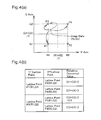
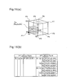
- Fig. 16 shows allocation of the image data Dx to the first lattice point and the second lattice point when the respective components Rx, Gx, and Bx of the image data Dx are closer to the corresponding lower coordinate values than the corresponding upper coordinate values, that is, when the image data Dx is in a hatched range of Fig. 16(a).
- the tone values Rx, Gx, and Bx of the R, G, and B components of the image data Dx are closer to the lower coordinate values R1, G1, and B1 respectively.
- the lower coordinate values R1, G1, and B1 are thus always set to the respective components of the first lattice point, as discussed previously with reference to Fig. 14(a).
- the respective components of the second lattice point may be set equal to the lower coordinate values R1, G1, and B1 or equal to the upper coordinate values R2, G2, and B2 according to the setting of the second noise Ns2, as discussed previously with reference to Fig. 14(b).
- Fig. 16(b) shows the tone values of the respective components in the possible combinations of the first lattice point and the second lattice point.
- the tone values R1, G1, and B1 corresponding to the lower coordinate values are set to the R, G, and B components of the first lattice point.
- a lattice point P1 (R1,G1,B1) is allocated to the first lattice point.
- the R component of the second lattice point is set equal to either the tone value R1 (corresponding to the lower coordinate value) or the tone value R2 (corresponding to the upper coordinate value).
- the G component of the second lattice point is set equal to either the tone value G1 (corresponding to the lower coordinate value) or the tone value G2 (corresponding to the upper coordinate value).
- the B component of the second lattice point is set equal to either the tone value B1 (corresponding to the lower coordinate value) or the tone value B2 (corresponding to the upper coordinate value).
- the lattice point P1 R1,G1,B1
- a lattice point P2 R2,G1,B1
- a lattice point P3 R2,G2,B1
- a lattice point P4 R1,G2,B1
- a lattice point P5 R1,G1,B2
- a lattice point P6 R2,G1,B2
- a lattice point P7(R2,G2,B2)
- a lattice point P8 R1,G2,B2
- the symbol 'closed circle' in Fig. 16(a) represents allocation of the lattice point P1 to the first lattice point.
- the symbols 'open circle' in Fig. 16(a) represent allocation of one of these lattice points P1 through P8 to the second lattice point.
- Fig. 17(b) shows the tone values of the respective components in the possible combinations of the first lattice point and the second lattice point.
- Either one of the lattice point P1 (R1,G1,B1) and the lattice point P5 (R1,G1,B2) is allocated to the first lattice point, whereas one of the lattice point P5 (R1, G1, B2), the lattice point P8 (R1,G2,B2), the lattice point P6 (R2,G1,B2), and the lattice point P7 (R2,G2,B2) is allocated to the second lattice point.
- FIG. 17(a) represent allocation of either one of the lattice points P1 and P5 to the first lattice point.
- the symbols 'open circle' in Fig. 17(a) represent allocation of one of the lattice points P5, P6, P7, and P8 to the second lattice point.
- the lattice point allocation process (the pre-conversion process) shown in the flowchart of Fig. 11 selects the first lattice point and the second lattice point according to the coordinate values of the target image data Dx.
- An identical lattice point may be selected in an overlapping manner as the first lattice point and the second lattice point.
- the program exits from the routine of the pre-conversion process shown in the flowchart of Fig. 11 and returns to the routine of the pre-conversion / color conversion process shown in the flowchart of Fig. 10.
- the program carries out the color conversion process (step S204 in the flowchart of Fig. 10).
- the pre-conversion process allocates the image data Dx expressed by the tone values of the R, G, and B color components to the first lattice point and the second lattice point. Each of these lattice points is also expressed by a combination of the coordinate values of the R, G, and B components.
- the subsequent color conversion process converts the coordinate values of the R, G, and B components into CMY image data expressed by the tone values of the color inks used in the color printer 200, that is, the C, M, and Y color inks.
- Fig. 18 is a flowchart showing a processing routine of the color conversion process carried out subsequent to the pre-conversion process.
- the printer driver 12 executes the color conversion process by utilizing the functions of the CPU 102 in the computer 100. The details of the color conversion process are discussed with reference to the flowchart of Fig. 18.
- the printer driver 12 When the program enters the routine of the color conversion process, the printer driver 12 first reads the tone values of the respective color components stored at the first lattice point in the LUT (color conversion table) (step S400). As described previously, a combination of the tone values of the respective, color inks used in the color printer 200, for example, the C, M, and Y color inks, is stored at each lattice point in the LUT. The processing of step S400 reads the tone values of the respective color components stored at the first lattice point, so as to convert the coordinate values of the R, G, and B components representing the first lattice point into the tone values of the C, M, and Y components.
- the following description is on the assumption that the tone values of only the C, M, and Y color components are stored at each lattice point in the LUT.
- the tone values of additional color inks used in the color printer 200 for example, K (black) ink, may also be stored at each lattice point in the LUT.
- the printer driver 12 subsequently reads the tone values of the C, M, and Y components stored at the second lattice point in the LUT, so as to convert the coordinate values of the R, G, and B components representing the second lattice point into the tone values of the C, M, and Y components (step S402).
- the printer driver 12 After reading the tone values of the C, M, and Y components stored at the first lattice point and the second lattice point, the printer driver 12 calculates an arithmetic mean of the tone values of the first lattice point and the second lattice point with regard to each component and thereby specifies CMY image data Dcx corresponding to the target RGB image data Dx (step S404).
- C1, M1, and Y1 represent the tone values of the C, M, and Y components read from the first lattice point
- C2, M2, and Y2 represent the tone values of the C, M, and Y components read from the second lattice point.
- the program exits from the processing routine of the color conversion process shown in the flowchart of Fig. 18 and returns to the processing routine of the pre-conversion / color conversion process shown in the flowchart of Fig. 10.
- the RGB image data read at step S200 in the flowchart of Fig. 10 has been converted to the CMY image data Dcx expressed by the tone values of the C, M, and Y components via the first lattice point and the second lattice point.
- the tone value of each component of the CMY image data Dcx is the mean of the tone values read from the first lattice point and the second lattice point with regard to the component.
- the tone value of each component of the CMY image data Dcx may be a value that internally divides the tone values read from the two lattice points at a predetermined ratio or at an arbitrary ratio.
- the resulting color-converted image data Dcx is specified by internally dividing the tone value C1 stored at the lattice point P1 and the tone value C2 stored at the lattice point P2 at an inverse ratio of the distance.
- Fig. 19(c) shows setting of the second lattice point.
- the second lattice point is set according to the result of the comparison between the second decision data Dr2 and the threshold value th.
- the lattice point P1 is allocated to the second lattice point.
- the second decision data Dr2 is greater than the threshold value th, on the contrary, the lattice point P2 is allocated to the second lattice point.
- the second decision data Dr2 is obtained by adding the first noise Ns1 and the tone value (R2-R1)/2 to the image data Dx, where the first noise Ns1 takes an arbitrary value in a range of 0 to (R2-R1)/2.
- the second decision data Dr2 obtained by adding the first noise Ns1 and the tone value (R2-R1)/2 to the tone value Dx takes an arbitrary value in a range of a tone value ⁇ R2-(R2-R1)/4 ⁇ to a tone value ⁇ R2+(R2-R1)/4 ⁇ with a substantially equal probability.
- the possible range of the second decision data Dr2 is shown as a hatched area in Fig. 19(c).
- the image data Dx is allocated to the lattice point P1.
- the second decision data Dr2 is greater than the threshold value th in (that is, on the right side of) the hatched range of Fig. 19(c), on the contrary, the image data Dx is allocated to the lattice point P2.
- the second lattice point is set either at the lattice point P1 or at the lattice point P2 with substantially the same probability.
- the image data Dx is allocated to either one of the lattice points P1 and P2 to make the ratio of the lattice point P1 to the lattice point P2 equal to 3 to 1.
- the image data Dx is converted to the tone value C1 or the tone value C2 at the ratio of 3 to 1.
- the image data Dx has the tone value that internally divides the lattice points P1 and P2 at the ratio of 1 to 3.
- the resulting tone value of the color-converted image data specified by the procedure of the embodiment coincides with the tone value calculated by the interpolation technique, regardless of the ratio of internal division of two lattice points.
- Individual image data has a pre-conversion error due to allocation of the image data to either one of the lattice points P1 and P2. In the case of processing a large number of image data, however, the pre-conversion errors arising in the respective image data are cancelled mutually. This gives the result coincident with the calculation by the interpolation technique.
- the pre-conversion / color conversion procedure of the embodiment first carries out the pre-conversion process to allocate target image data to multiple lattice points in the LUT.
- the procedure subsequently reads the tone values of each color component stored at the multiple lattice points and combines the read tone values with regard to the color component to specify the color-converted image data corresponding to the target image data.
- the arrangement of allocating the image data to multiple lattice points prior to color conversion significantly reduces the resultant pre-conversion error, compared with the prior art pre-conversion technique that allocates the image data to only one lattice point, based on the principle discussed previously.
- the pre-conversion process of the embodiment that allocates the image data to the two lattice points ensures the higher accuracy of subsequent color conversion. This is ascribed to the following reason.
- the tone value rounded to an integer is stored at each lattice point in the LUT.
- the resulting image data obtained by color conversion subsequent to the prior art pre-conversion is accordingly an integral value including a round error.
- the resulting image data obtained by color conversion subsequent to the pre-conversion of the embodiment is, on the other had, calculated from the tone values (integers) stored at the two lattice points and may thus take a decimal value.
- the color conversion subsequent to the pre-conversion of the embodiment accordingly makes the resulting image data free from the round error. This arrangement thus ensures the higher accuracy of color conversion.
- the pre-conversion / color conversion procedure of the embodiment may calculate the arithmetic mean of the tone values read from the multiple lattice points to specify the resulting color-converted CMY image data Dcx corresponding to the target RGB image data Dx.
- the arithmetic mean is calculated at a high speed. Compared with the color conversion by the interpolation technique, the arrangement of the embodiment ensures the extremely higher speed color conversion. Especially when the number of the multiple lattice points is a multiple number of 2 (for example, 2 or 4), the arithmetic mean is calculated very quickly by utilizing the bit shifting technique in the CPU.
- the pre-conversion / color conversion procedure of the embodiment reads the tone values stored at multiple lattice points and thus naturally increases the total processing time, compared with the prior art pre-conversion technique.
- the process of reading the tone values stored at the lattice points is, however, implemented at an extremely high speed.
- the increase in number of lattice points, from which the tone values are read, thus only slightly extends the total processing time.
- the processing speed of the pre-conversion / color conversion procedure of the embodiment is thus comparable to that of the prior art pre-conversion technique.
- the procedure of the above embodiment calculates the arithmetic mean of the tone values stored at the first lattice point and the second lattice point to specify the color-converted image data Dcx.
- this arrangement enables the pre-conversion errors arising in the individual image data to be mutually cancelled.
- the resulting color-converted image data is thus equivalent to the result by the conventional interpolation technique.
- the method of calculating the arithmetic mean of the tone values read from the multiple lattice points is not restrictive at all, but the color converted image data may be specified by another technique.
- the procedure of the first embodiment utilizes the random noises based on random digits as the first noise Ns1 and the second noise Ns2.
- the error diffusion technique may be applied, instead of utilizing such random noises.
- the error diffusion technique diffuses an error arising in a certain pixel to peripheral non-processed pixels in the course of processing.
- the processing based on the error diffusion technique is described briefly as one possible modification of the first embodiment.
- the pre-conversion / color conversion procedure shown in the flowchart of Fig. 10 generally starts the processing in a pixel at the upper left corner of an image as a starting pixel and sequentially carries out the processing from the left-end pixel to the right-end pixel on each line. After the right-end pixel on a certain line, the processing shifts to a new line immediately below the certain line and proceeds from the left-end pixel to the right-end pixel on the new line. This series of processing is repeated until the processing of all the pixels in one image plane has been completed.
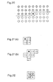
- Fig. 20 shows a mid state of the pre-conversion / color conversion process with regard to image data of one image plane.
- the symbol '*' shown on the center of Fig. 20 represents a target pixel, which is currently being processed.
- the hatched circles in an area above and on the left of the target pixel represent processed pixels, whereas the open circles in the residual area below and on the right of the target pixel represent non-processed pixels.
- the procedure shifts the target pixel rightward by one pixel, specifies the right adjacent pixel as a new target pixel, and allocates the image data of the new target pixel to two lattice points in the LUT.
- the allocation is carried out by comparing the first decision data Dr1 as the sum of the first noise Ns1 and the image data Dx and the second decision data Dr2 as the sum of the second noise Ns2 and the image data Dx with the threshold value th.
- the procedure of the first embodiment uses a random digit to set the first noise Ns1.
- the modified example utilizing the error diffusion method uses the total of divisions of errors diffused from peripheral processed pixels to the target pixel as the first noise Ns1.
- Fig. 22 conceptually shows diffusion of divisions of errors arising in peripheral processed pixels to a target pixel.
- the weight coefficients shown in Fig. 21(a) are used for the error diffusion.
- the rectangle with '*' represents the target pixel, and the rectangles with hatched circles represent the processed pixels.
- the arrows extending from the processed pixels to the target pixel schematically show diffusion of error divisions.
- the procedure of this modified example specifies the sum of the error divisions diffused from these peripheral pixels as the first noise Ns1 and the sum of the first noise and the mean of the tone values read from the lattice points as the second noise Ns2.
- the modified example based on the error diffusion technique specifies the total of the error divisions diffused from the peripheral non-processed pixels as the first noise Ns1 and exerts the similar effects to those of the first embodiment. This is described briefly.
- the image data Dx may be allocated twice to an identical lower lattice point (that is, a lattice point having the smaller coordinate value) or may otherwise be allocated to an upper lattice point (that is, the lattice point having the greater coordinate value) and the lower lattice point.
- the initial value of the first noise Ns1 is set equal to '0'. As discussed previously with reference to Fig. 14, in this case, both the first lattice point and the second lattice point are allocated to the lower lattice point. This causes an error in the target pixel.
- the error arising in the target pixel is smaller than half the tone value difference between the upper lattice point and the lower lattice point.
- a next target pixel adjacent to the current target pixel has divisions of errors that arise in peripheral processed pixels in this manner and are diffused from the processed pixels.
- the first noise Ns1 in the next target pixel is accordingly smaller than half the tone value difference between the upper lattice point and the lower lattice point.
- the maximum error arising in each target pixel is the tone value that is half the interval between the two lattice points.
- the image data Dx may be allocated to the upper lattice point and the lower lattice point or may otherwise be allocated twice to the identical upper lattice point.
- the initial value of the first noise Ns1 is set equal to '0'. As discussed previously with reference to Fig. 15, in this case, the first lattice point is allocated to the lower lattice point and the second lattice point is allocated to the upper lattice point.
- the error arising in the target pixel is smaller than half the tone value difference between the upper lattice point and the lower lattice point.
- a next target pixel adjacent to the current target pixel has divisions of errors that arise in peripheral processed pixels in this manner and are diffused from the processed pixels.
- the first noise Ns1 in the next target pixel is accordingly smaller than half the tone value difference between the upper lattice point and the lower lattice point.
- the maximum error arising in each target pixel is the tone value that is half the interval between the two lattice points.
- the total error of the two lattice points takes an arbitrary value in the range from the tone value '0' to the tone value that is half the interval between the two lattice points including the image data Dx, regardless of the value of the image data Dx. Divisions of such errors are diffused from peripheral processed pixels to each target pixel.
- the first noise Ns1 in each target pixel takes an arbitrary value in the range from the tone value '0' to the tone value that is half the interval between the two lattice points including the image data Dx.
- the first noise Ns1 in the procedure of utilizing the errors by the error diffusion technique is equivalent to the first noise Ns1 in the procedure of generating the errors based on random digits.
- the procedure of the modified example accordingly has the similar effects to those of the first embodiment discussed above.
- the error diffusion method has the function of canceling the errors arising in the peripheral pixels.
- the procedure of the modified example based on the error diffusion technique accordingly enables effective cancellation of the pre-conversion errors arising in the respective pixels and advantageously ensures printing of the higher-quality image.
- the procedure of the first embodiment allocates the image data Dx to the two lattice points, the first lattice point and the second lattice point.
- the number of lattice points, to which the image data Dx is allocated is not restricted to 2, but may be greater than 2. The following describes such a case as a pre-conversion / color conversion procedure of a second embodiment.
- Fig. 23 is a flowchart showing a processing routine of allocating image data to multiple lattice points (pre-conversion process) carried out in the second embodiment. This process is executed after the step of reading image data in the pre-conversion / color conversion process shown in the flowchart of Fig. 10.
- the primary difference from the pre-conversion process of the first embodiment discussed previously with reference to the flowchart of Fig. 11 is an increase in number of the lattice points, to which the image data is allocated, to 3.
- the process of allocating the image data to the three lattice points is readily expandable to the process of allocating the image data to a greater number of lattice points.
- the following describes the process of allocating the image data to the three lattice points in the second embodiment with reference to the flowchart of Fig. 23.
- the printer driver 12 first detects the coordinate values of each lattice point in the vicinity of target image data Dx on the color space (step S500). As shown in Fig. 13, the procedure of step S500 selects a rectangular parallelepiped including the coordinate point of the target image data Dx among a large number of small rectangular parallelepipeds constituting the LUT (color conversion table) and specifies the coordinate values of the respective vertexes of the selected rectangular parallelepiped with regard to each color component.
- the printer driver 12 subsequently sets an upper coordinate value Gup to the threshold value th with regard to each color component (step S502).
- the upper coordinate value Gup corresponds to the greater tone value when the coordinate values of the lattice points detected at step S500 are grouped into the respective color components.
- the upper coordinate values Gup of the R component, the G component, and the B component are respectively equal to the tone value R2, the tone value G2, and the tone value B2.
- the lower coordinate value Glw corresponds to the smaller tone value when the coordinate values of the lattice points detected at step S500 are grouped into the respective color components.
- the lower coordinate values Glw of the R component, the G component, and the B component are respectively equal to the tone value R1, the tone value G1, and the tone value B1. This series of processing is carried out with regard to the respective color components to specify the first lattice point.
- the printer driver 12 calculates a second noise Ns2 and second decision data Dr2 for setting a second lattice point (step S508).
- the second noise Ns2 is the sum of the first noise Ns1 and a tone value that internally divides the lower coordinate value Glw and the upper coordinate value Gup adjoining to the image data Dx at a ratio of 1 to 3. Addition of the tone value that internally divides the coordinate values Glw and Gup at the ratio of 1 to 3 is ascribed to allocation of the image data Dx to the three lattice points.
- the second noise Ns2 is the sum of the first noise Ns1 and a tone value that internally divides the lower coordinate value Glw and the upper coordinate value Gup at a ratio of 1 to N.
- the printer driver 12 subsequently sets a second lattice point based on the result of comparison between the calculated second decision data Dr2 and the preset threshold value th (step S510).
- the upper coordinate value Gup is set to the coordinate value of the second lattice point with regard to the certain color component. Otherwise the lower coordinate value Glw is set to the coordinate value of the second lattice point.
- the program then sets a third lattice point in a similar manner to that of the first lattice point and the second lattice point.
- the printer driver 12 calculates a third noise Ns3 and third decision data Dr3 (step S512), and sets the third lattice point based on the result of comparison between the calculated third decision data Dr3 and the preset threshold value th (step S514).
- the third noise Ns3 is the sum of the first noise Ns1 and a tone value that internally divides the lower coordinate value Glw and the upper coordinate value Gup adjoining to the image data Dx at a ratio of 2 to 3.
- the third decision data Dr3 is obtained by adding the third noise Ns3 to the image data Dx.
- the upper coordinate value Gup is set to the coordinate value of the third lattice point with regard to the certain color component. Otherwise the lower coordinate value Glw is set to the coordinate value of the third lattice point. This series of processing is carried out with regard to the respective color components to specify the third lattice point.
- Fig. 24 conceptually shows allocation of the image data Dx to the three lattice points.
- Figs. 24(a), 24(b), and 24(c) respectively show allocation of the image data Dx to the first lattice point, the second lattice point, and the third lattice point.
- Fig. 24 regards the process of setting the coordinate values of only the R component at the respective lattice points. The explanation is naturally applicable to the other color components G and B.
- the first decision data Dr1 obtained by adding the first noise Ns1 to the image data Dx takes an arbitrary value in a hatched range of Fig. 24(a).
- the first decision data Dr1 never exceeds the threshold value th.
- the coordinate value R1 is thus constantly set to the R component of the first lattice point.
- the second decision data Dr2 obtained by adding the second noise Ns2 to the image data Dx may be smaller than the threshold value th or greater than the threshold value th according to the value of the second noise Ns2 as shown by a hatched range in Fig. 24(b).
- the coordinate value R1 is set to the R component of the second lattice point when the second decision data Dr2 is smaller than the threshold value th.
- the coordinate value R2 is set to the R component of the second lattice point when the second decision data Dr2 is greater than the threshold value th.
- the third decision data Dr3 obtained by adding the third noise Ns3 to the image data Dx is always greater than the threshold value th, regardless of the value of the third noise Ns3, as shown by a hatched range in Fig. 24(c).
- the coordinate value R2 is thus constantly set to the R component of the third lattice point.
- Fig. 25 shows settings of the R components of the three lattice points according to the value of the image data Dx.
- the upper most row shows the settings when the image data Dx is in a range from the coordinate value R1 to the coordinate value ⁇ R1+(R2-R1)/3 ⁇ .
- the middle row shows the settings when the image data Dx is in the range from the coordinate value ⁇ R1+(R2-R1)/3 ⁇ to the coordinate value ⁇ R1+((R2-R1) ⁇ 2/3), that is, in the case of Fig. 24.
- the lower most row shows the settings when the image data Dx is in a range from the coordinate value ⁇ R1+((R2-R1) ⁇ 2/3) to the coordinate value R2.
- the image data Dx is defined by the tone values of the R, G, and B components, and the resulting color-converted image data is defined by the tone values of the C, M, and Y components.
- a tone value C1 is stored as the color-converted tone value at the lattice point of the coordinate value R1 in the LUT.
- a tone value C2 is stored at the lattice point of the coordinate value R2 in the LUT.
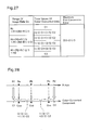
- Fig. 27 shows the resulting tone values obtained by the color conversion of the three lattice points set by the pre-conversion process of the second embodiment.
- the first lattice point, the second lattice point, and the third lattice point are set according to the value of the image data Dx.
- the tone values of the color-converted image data are thus varied according to the value of the image data Dx.
- the color converted image data has either the tone value C1 or a tone value ⁇ (2/3) ⁇ C1+(1/3) ⁇ C2 ⁇ .
- the color-converted image data has either the tone value ⁇ (2/3) ⁇ C1+(1/3) ⁇ C2 ⁇ or a tone value ⁇ (1/3) ⁇ C1+(2/3) ⁇ C2 ⁇ .
- the image data Dx is in the range from the coordinate value ⁇ R1+((R2-R1) ⁇ 2/3) to the coordinate value R2
- the color-converted image data has either the tone value ⁇ (1/3) ⁇ C1+(2/3) ⁇ C2 ⁇ or the tone value C2.
- the maximum pre-conversion error does not exceed a tone value (C2-C1)/3, regardless of the range of the image data Dx. This is described with reference to Fig. 28.
- Fig. 28 shows an example of color conversion of the RGB image data to the tone values of the C, M, and Y color components.
- the illustration is focused on only the R component of the RGB image data and the tone value of the C color component.
- the tone value C1 is stored at the lattice point of the coordinate value R1 in the LUT, and the tone value C2 is stored at the lattice point of the coordinate value R2.
- the image data has an R component Ra that is in the range from the coordinate value R1 to the coordinate value ⁇ R1+(R2-R1)/3 ⁇ .
- the image data Ra is converted into a tone value Cca by color conversion based on the interpolation technique.
- arrow of broken line extending from the coordinate value Ra of the image data on the R axis to the C component of the color-converted image data in Fig. 28 schematically shows conversion of the image data Ra into the tone value Cca by the color conversion based on the interpolation technique.
- the pre-conversion error arising by color conversion of the image data Ra is maximized (that is, the length of the arc of the broken line is maximized), when the color-converted image data has the tone value ⁇ (2/3) ⁇ C1+(1/3) ⁇ C2 ⁇ while the image data Ra is approximate to the coordinate value R1 or when the color-converted image data has the tone value C1 while the image data Ra is approximate to the coordinate value ⁇ R1+(R2-R1)/3 ⁇ .
- the maximum pre-conversion error is the tone value (C2-C1)/3.
- the above explanation is also applicable to an R component Rb of the image data that is in the range from the coordinate value ⁇ R1+(R2-R1)/3 ⁇ to the coordinate value ⁇ R1+((R2-R1) ⁇ 2/3) ⁇ , as well as to an R component Rc of the image data that is in the range from the coordinate value ⁇ R1+((R2-R1) ⁇ 2/3) ⁇ to the coordinate value R2.
- the image data Rb and the image data Rc are respectively converted into a tone value Ccb and a tone value Ccc by color conversion based on the interpolation technique. As shown in Fig.
- the pre-conversion / color conversion process of the second embodiment converts the image data Rb into either the tone value ⁇ (2/3) ⁇ C1+(1/3) ⁇ C2 ⁇ or the tone value ⁇ (1/3) ⁇ C1+(2/3) ⁇ C2 ⁇ , while converting the image data Rc into either the tone value ⁇ (1/3) ⁇ C1+(2/3) ⁇ C2 ⁇ or the tone value C2.
- the maximum pre-conversion error is the tone value (C2-C1)/3.
- the maximum pre-conversion error is 1/3 of the interval between the coordinate values of the lattice points including the image data Dx, regardless of the value of the image data Dx. This arrangement thus significantly reduces the pre-conversion error, compared with the prior art pre-conversion technique.
- the pre-conversion process of the second embodiment allocates the image data to the three lattice points, and the color conversion process is accordingly required to read the tone values stored at the three lattice points in the LUT.
- the increase in number of lattice points, from which the tone values are read slightly extends the processing time required for color conversion.
- the arrangement of the second embodiment still significantly shortens the total processing time, compared with the conventional color conversion method utilizing the interpolation technique. This is described with reference to Fig. 29.
- Fig. 29 conceptually shows the image data Dx included in a rectangular parallelepiped in the LUT.
- the pre-conversion process of the second embodiment allocates the image data Dx to the three lattice points.
- the conventional color conversion method that utilizes the interpolation technique for color conversion of the image data Dx should refer to four lattice points P1, P2, P4, and P5 and read the tone values stored at these lattice points P1, P2, P4, and P5, even in the case of tetrahedral interpolation that has the less number of lattice points to be referred to.
- the number of lattice points to be referred to for reading the tone values is 3 in the pre-conversion / color conversion procedure of the second embodiment, but is 4 in the conventional color conversion method utilizing the interpolation technique. Namely the processing time required for color conversion in the pre-conversion / color conversion procedure of the second embodiment is shorter than that in the conventional color conversion method utilizing the interpolation technique.
- the interpolation requires specification of the distances between the image data Dx and the four lattice points P1, P2, P4, and P5.
- the color conversion process of the second embodiment may specify the color-converted image data by simply calculating the arithmetic mean of the tone values read from the multiple lattice points. It is accordingly not necessary to specify the distances between the image data Dx and the respective lattice points. Even in the case of the increased number of lattice points, to which the image data is allocated, the pre-conversion / color conversion process of the second embodiment still significantly reduces the total processing time, compared with the conventional color conversion method utilizing the interpolation technique.
- the printer driver 12 calculates the mean of an upper coordinate value (Gup) and a lower coordinate value (Glw) and sets the calculated mean to a threshold value th (step S702).
- the upper coordinate value Gup corresponds to the greater tone value when the coordinate values of the lattice points detected at step S700 are grouped into the respective color components.
- the lower coordinate value Glw corresponds to the smaller tone value.
- the upper coordinate value Gup and the lower coordinate value Glw are present with regard to each color component of the image data Dx, and the threshold value th is also set for each color component.
- the color component is not specified in the following description. The description is applicable to all the color components of the image data, unless otherwise specified.
- the target image data Dx is compared with the setting of the threshold value th with regard to each color component (step S704).
- the lower coordinate value Glw is set to a coordinate value Pre1 of the first lattice point (step S706).
- the upper coordinate value Gup is set to the coordinate value Pre1 of the first lattice point (step S708).
- Fig. 31 conceptually shows setting of the first lattice point.
- a tone value R1 corresponding to the lower coordinate value Glw is set to the R component of the first lattice point.
- the arrow of solid line in Fig. 31(a) schematically shows setting of the tone value R1 to the coordinate value of the first lattice point.
- Fig. 31(b) shows the setting when the R component Rx of the image data is greater than the threshold value th.
- the pre-conversion process of the third embodiment utilizes a noise to set the second lattice point.
- the process of setting the second lattice point first generates a noise Ns (step S712).
- the noise Ns may be identical with the first noise Ns1 used in the pre-conversion process of the first embodiment.
- the noise Ns is calculated with regard to each of the R, G, and B color components, while the random digit generated by the function RD[0,1] may be an identical value for all the components R, G, and B.
- the rectangular parallelepiped including the coordinate point of the target image data is a cube, an identical value may be set to the noise Ns for all the color components.
- the noise may not be specified by using a random digit, but the error by the error diffusion method may be used for the noise as discussed in the modified example of the first embodiment.
- the lower coordinate value Glw is set to the coordinate value Pre2 of the second lattice point (step S720). This series of processing is carried out with regard to each color component to specify the second lattice point.
- FIG. 32(a) schematically shows the setting of the tone value R1 to the R component of the second lattice point, when the decision data Dr is smaller than the threshold value th.
- the arrow of broken line extending from a right side of the threshold value th in the hatched range to the coordinate value R2 in Fig. 32(a) schematically shows the setting of the tone value R2 to the R component of the second lattice point, when the decision data Dr is greater than the threshold value th.
- the pre-conversion process of the third embodiment specifies the first lattice point and the second lattice point in the above manner and gives similar results to those obtained by the pre-conversion process of the first embodiment discussed previously.
- the pre-conversion process of the third embodiment uses only one noise to set the two lattice points. This arrangement simplifies the processing flow.
- the pre-conversion process of the third embodiment allocates the image data Dx to the two lattice points.
- the number of the lattice points, to which the image data is allocated is not restricted to 2.
- the pre-conversion process of the third embodiment is expandable to be applied for allocation of the image data to a greater number of lattice points. This application is discussed below as a pre-conversion process of a modified example.
- Fig. 33 shows expansion of the pre-conversion process of the third embodiment to be applied for allocation of image data to three lattice points.
- the closed triangle represents the position of the R component Rx of the image data Dx.
- R1 and R2 are tone values respectively corresponding to the lower coordinate value Glw and the upper coordinate value Gup adjoining to the image data Dx.
- the pre-conversion process in the modified example of the third embodiment uses three threshold values th1, th2, and th3, which are respectively set equal to a tone value ⁇ R1+(R2-R1)/3 ⁇ , a tone value ⁇ R1+(R2 ⁇ R1) ⁇ 2/3 ⁇ , and a tone value R2.
- Fig. 33(a) shows the settings when the R component Rx of the image data Dx is in a range from the tone value R1 to the tone value ⁇ R1+(R2-R1)/3 ⁇ .
- Fig. 33(b) shows the settings when the R component Rx of the image data Dx is in a range from the tone value ⁇ R1+(R2-R1)/3 ⁇ to the tone value ⁇ R1+((R2-R1) ⁇ 2/3).
- Fig. 33(c) shows the settings when the R component Rx of the image data Dx is in a range from the tone value ⁇ R1+((R2-R1) ⁇ 2/3) to the tone value R2.
- Fig. 33 shows only the process of setting the coordinate values of the first through the third lattice points with regard to the R component. The principle of the setting is also applicable for the other components G and B.
- the first lattice point and the second lattice point are set equal to the tone value R1 (corresponding to the lower coordinate value).
- the arrow of solid line and the arrow of broken line respectively extending from the image data Rx to the tone value R1 in Fig. 33(a) show the settings of the tone value R1 to the R components of the first lattice point and the second lattice point.
- the decision data Dr is obtained by adding the noise Ns to the image data Dx.
- the calculated decision data Dr is compared with the threshold value th1.
- a hatched range in Fig. 33(a) shows a possible range of the decision data Dr.
- the R component of the third lattice point is set equal to the tone value R1. Otherwise the R component of the third lattice point is set equal to the tone value R2.
- the arrows of one-dot chain line in Fig. 33(a) schematically show the setting of the R component of the third lattice point equal to either the tone value R1 or the tone value R2. This series of processing is carried out with regard to the respective color components, so as to specify the first lattice point, the second lattice point, and the third lattice point.
- the R component of the first lattice point is set equal to the tone value R1 (corresponding to the lower coordinate value), and the R component of the second lattice point is set equal to the tone value R2 (corresponding to the upper coordinate value).
- the arrow of solid line extending from the image data Rx to the tone value R1 in Fig. 33(b) schematically shows the setting of the R component of the first lattice point equal to the tone value R1.
- the arrow of broken line extending from the image data Rx to the tone value R2 in Fig. 33(b) schematically shows the setting of the R component of the second lattice point equal to the tone value R2.
- the three lattice points are specified in a similar manner.
- the procedure is described briefly with reference to Fig. 33(c).
- the tone value R2 (corresponding to the upper coordinate value) is set to both the R components of the first lattice point and the second lattice point.
- the procedure then adds the noise Ns to the R component Rx of the image data Dx to calculate the decision data Dr, and compares the calculated decision data Dr with the threshold value th3.
- the pre-conversion process in the modified example of the third embodiment uses only one noise to allocate the image data to the three lattice points. This arrangement ensures the higher-speed pre-conversion process.
- the embodiments discussed above regard the case of converting the image data expressed in the RGB color system into the image data expressed in the CMY color system.
- the technique of the invention is not restricted to conversion of image data in a certain color system into image data in a different color system.
- the principle of the invention is also applicable for correction of the image data in an identical color system.
Landscapes
- Engineering & Computer Science (AREA)
- Multimedia (AREA)
- Signal Processing (AREA)
- Image Processing (AREA)
- Facsimile Image Signal Circuits (AREA)
- Color Image Communication Systems (AREA)
Abstract
Description
The above and other objects, features, aspects, and advantages of the present invention will become more apparent from the following detailed description of the preferred embodiments with the accompanying drawings.
The above embodiments are to be considered in all aspects as illustrative and not restrictive. There may be many modifications, changes, and alterations without departing from the scope or spirit of the main characteristics of the present invention.
The scope and spirit of the present invention are indicated by the appended claims, rather than by the foregoing description.
Claims (42)
- An image processing apparatus that receives target color image data, which is expressed by a coordinate value in at least one-dimensional color space, makes the target color image data subjected to a preset series of correction, and outputs corrected color image data, said image processing apparatus comprising:a correction table that stores corrected data, which is expressed by a coordinate value, at each of lattice points defined by division of the color space with regard to each dimension;a lattice point selection module that selects N (where N is an integer of not less than 2) lattice points in an overlap-allowable manner among lattice points that have distances of not longer than a preset value from the coordinate value of the target color image data; anda corrected data specification module that specifies corrected color image data corresponding to the target color image data, based on the corrected data stored at the selected N lattice points.
- An image processing apparatus in accordance with claim 1, wherein said lattice point selection module selects the N lattice points in an undefined manner.
- An image processing apparatus in accordance with claim 2, wherein said lattice point selection module selects N divisional tone values with regard to each dimension, which represent tone values of dividing each dimension of the color space, so as to specify the N lattice points, and
the selection of the divisional tone values is carried out in such a manner that a divisional tone value closer to the coordinate value of the target color image data is selected with a higher probability. - An image processing apparatus in accordance with claim 2, wherein said corrected data specification module calculates an arithmetic mean of the corrected data stored at the N lattice points and specifies the corrected color image data corresponding to the target color image data, based on the calculated arithmetic mean.
- An image processing apparatus in accordance with claim 1, wherein said lattice point selection module, when the target color image data is expressed by a coordinate value in an M-dimensional color space (where M is an arbitrary positive integer), selects multiple but not greater than M lattice points as the N lattice points.
- An image processing apparatus in accordance with claim 5, wherein said lattice point selection module selects the N lattice points in an undefined manner.
- An image processing apparatus in accordance with claim 5, wherein said lattice point selection module selects multiple but not greater than M divisional tone values with regard to each dimension, which represent tone values of dividing each dimension of the color space, so as to specify the multiple lattice points, and
the selection of the divisional tone values is carried out in such a manner that a divisional tone value closer to the coordinate value of the target color image data is selected with a higher probability. - An image processing apparatus in accordance with claim 5,
wherein said corrected data specification module calculates an arithmetic mean of the corrected data stored at the selected multiple lattice points and specifies the corrected color image data corresponding to the target color image data, based on the calculated arithmetic mean. - An image processing apparatus in accordance with claim 1, wherein said corrected data specification module reads the corrected data stored at the selected N lattice points from said correction table and calculates an arithmetic mean of the corrected data read from the selected N lattice points, so as to specify corrected color image data corresponding to the target color image data.
- An image processing apparatus in accordance with claim 9, wherein said lattice point selection module selects the N lattice points in an undefined manner.
- An image processing apparatus in accordance with claim 9, wherein said lattice point selection module selects N divisional tone values with regard to each dimension, which represent tone values of dividing each dimension of the color space, so as to specify the N lattice points, and
the selection of the divisional tone values is carried out in such a manner that a divisional tone value closer to the coordinate value of the target color image data is selected with a higher probability. - An image processing apparatus in accordance with any one of claims 2, 5, and 9, wherein said lattice point selection module selects K (where K is an integer of not less than 2) lattice points, such that a difference between an expected probabilistic value of each of the K lattice points and the coordinate value of the target color image data is not greater than a preset level.
- An image processing apparatus in accordance with claim 12, wherein said lattice point selection module selects K divisional tone values with regard to each dimension, which represent tone values of dividing each dimension of the color space, so as to specify the K lattice points.
- An image processing apparatus in accordance with claim 13, wherein said lattice point selection module comprises:a decision data generation sub-module that adds a noise to the coordinate value of the target color image data to generate decision data with regard to each dimension; anda divisional tone value selection sub-module that compares the decision data of each dimension with a predetermined threshold value, so as to select the K divisional tone values with regard to each dimension.
- An image processing apparatus in accordance with claim 14, said image processing apparatus further comprising:a divisional tone value specification module that specifies, with regard to each dimension, a first divisional tone value and a second divisional tone value out of the K divisional tone values, wherein said first divisional tone value is closest to the coordinate value of the target color image data among smaller divisional tone values than the coordinate value of the target color image data, and said second divisional tone value is closest to the coordinate value of the target color image data among greater divisional tone values than the coordinate value of the target color image data; anda noise generation module that calculates an inter-lattice tone value difference between the first divisional tone value and the second divisional tone value and generates K noises of different expected values in a range from a tone value '0' to the inter-lattice tone value difference, with regard to each dimension,wherein said decision data generation sub-module adds the K noises to the coordinate value of the target color image data, so as to generate K decision data with regard to each dimension, andsaid divisional tone value selection module selects either of the first divisional tone value and the second divisional tone value based on a result of the comparison between each of the K decision data and the predetermined threshold value, so as to select the K divisional tone values.
- An image processing apparatus in accordance with claim 15, wherein said noise generation module comprises:a shift quantity calculation sub-module that calculates a tone value that is 1/K of the inter-lattice tone value difference as a shift quantity with regard to each dimension,a reference noise generation sub-module that generates noise in a range from a tone value '0' to the calculated shift quantity as a reference noise with regard to each dimension; anda noise shifting sub-module that shifts the reference noise by the calculated shift quantity (K-1) times, so as to generate the K noises of different expected values.
- An image processing apparatus in accordance with claim 14, said image processing apparatus further comprising:wherein said first divisional tone value is closest to the coordinate value of the target color image data among smaller divisional tone values than the coordinate value of the target color image data, and said second divisional tone value is closest to the coordinate value of the target color image data among greater divisional tone values than the coordinate value of the target color image data; anda divisional tone value specification module that specifies, with regard to each dimension, a first divisional tone value and a second divisional tone value out of the K divisional tone values,
a threshold value setting module that sets the second divisional tone value and (K-1) tone values, which equally divide an interval between the first divisional tone value and the second divisional tone value, as K threshold values,
wherein said decision data generation sub-module adds a noise corresponding to a tone value difference between the first divisional tone value and the second divisional tone value to the coordinate value of the target color image data, so as to generate the decision data with regard to each dimension, and
said divisional tone value selection sub-module selects either of the first divisional tone value and the second divisional tone value based on a result of the comparison between the generated decision data and each of the K threshold values, so as to select the K divisional tone values. - An image processing apparatus in accordance with claim 12, wherein said lattice point selection module selects two lattice points.
- An image processing apparatus in accordance with claim 12, said image processing apparatus further comprising:wherein said lattice point selection module selects a specified number of the lattice points according to the detected processing mode.a processing mode detection module that detects setting of a processing mode, which gives a priority to at least either of an execution speed of the preset series of correction and a correction accuracy of the target color image data,
- An image processing apparatus in accordance with claim 19, wherein said lattice point selection module selects a greater number of the lattice points in a certain setting of the processing mode that gives the priority to the correction accuracy over the execution speed than a number of lattice points in another setting of the processing mode that gives the priority to the execution speed over the correction accuracy.
- An image processing apparatus in accordance with claim 12, wherein the target color image data is RGB image data expressed by coordinate values in a color space defined by a red (R) axis, a green (G) axis, and a blue (B) axis, and
said correction table stores tone values of at least cyan, magenta, and yellow as the corrected data. - An image processing method that receives target color image data, which is expressed by a coordinate value in at least one-dimensional color space, makes the target color image data subjected to a preset series of correction, and outputs corrected color image data, said image processing method comprising the steps of:(A) storing corrected data, which is expressed by a coordinate value, at each of lattice points defined by division of the color space with regard to each dimension;(B) selecting N (where N is an integer of not less than 2) lattice points in an overlap-allowable manner among lattice points that have distances of not longer than a preset value from the coordinate value of the target color image data; and(C) specifying corrected color image data corresponding to the target color image data, based on the corrected data stored at the selected N lattice points.
- An image processing method in accordance with claim 22, wherein said step (B) selects the N lattice points in an undefined manner.
- An image processing method in accordance with claim 22, wherein said step (B), when the target color image data is expressed by a coordinate value in an M-dimensional color space (where M is an arbitrary positive integer), selects multiple but not greater than M lattice points as the N lattice points.
- An image processing method in accordance with claim 22, wherein said step (C) reads the corrected data stored at the selected N lattice points from said correction table and calculates an arithmetic mean of the corrected data read from the selected N lattice points, so as to specify corrected color image data corresponding to the target color image data.
- An image processing method in accordance with any one of claims 23 through 25, wherein said step (B) selects K (where K is an integer of not less than 2) lattice points, such that a difference between an expected probabilistic value of each of the K lattice points and the coordinate value of the target color image data is not greater than a preset level.
- An image processing method in accordance with any one of claims 23 through 25, wherein said step (B) selects two lattice points.
- A printing apparatus that receives target color image data, which is expressed by a coordinate value in at least one-dimensional color space, makes the target color image data subjected to a preset series of correction, and prints a resulting color image based on corrected color image data, said printing apparatus comprising:a correction table that stores corrected data, which is expressed by a coordinate value, at each of lattice points defined by division of the color space with regard to each dimension;a lattice point selection module that selects N (where N is an integer of not less than 2) lattice points in an overlap-allowable manner among lattice points that have distances of not longer than a preset value from the coordinate value of the target color image data;a corrected data specification module that specifies corrected color image data corresponding to the target color image data, based on the corrected data stored at the selected N lattice points; anda printing module that prints the resulting color image based on the corrected color image data.
- A printing apparatus in accordance with claim 28, wherein said lattice point selection module selects the N lattice points in an undefined manner.
- A printing apparatus in accordance with claim 28, wherein said lattice point selection module, when the target color image data is expressed by a coordinate value in an M-dimensional color space (where M is an arbitrary positive integer), selects multiple but not greater than M lattice points as the N lattice points.
- A printing apparatus in accordance with claim 28, wherein said corrected data specification module reads the corrected data stored at the selected N lattice points from said correction table and calculates an arithmetic mean of the corrected data read from the selected N lattice points, so as to specify corrected color image data corresponding to the target color image data.
- A printing apparatus in accordance with any one of claims 29 through 31, wherein said lattice point selection module selects K (where K is an integer of not less than 2) lattice points, such that a difference between an expected probabilistic value of each of the K lattice points and the coordinate value of the target color image data is not greater than a preset level.
- A recording medium, in which a computer program is recorded in a computer readable manner, said computer program actualizing an image processing method that receives target color image data, which is expressed by a coordinate value in at least one-dimensional color space, makes the target color image data subjected to a preset series of correction, and outputs corrected color image data,
said computer program causing a computer to attain the functions of:(A) storing corrected data, which is expressed by a coordinate value, at each of lattice points defined by division of the color space with regard to each dimension;(B) selecting N (where N is an integer of not less than 2) lattice points in an overlap-allowable manner among lattice points that have distances of not longer than a preset value from the coordinate value of the target color image data; and(C) specifying corrected color image data corresponding to the target color image data, based on the corrected data stored at the selected N lattice points. - A recording medium in accordance with claim 33, wherein said function (B) selects the N lattice points in an undefined manner.
- A recording medium in accordance with claim 33, wherein said function (B), when the target color image data is expressed by a coordinate value in an M-dimensional color space (where M is an arbitrary positive integer), selects multiple but not greater than M lattice points as the N lattice points.
- A recording medium in accordance with claim 33, wherein said function (C) reads the corrected data stored at the selected N lattice points from said correction table and calculates an arithmetic mean of the corrected data read from the selected N lattice points, so as to specify corrected color image data corresponding to the target color image data.
- A recording medium in accordance with any one of claims 34 through 36, wherein said function (B) selects K (where K is an integer of not less than 2) lattice points, such that a difference between an expected probabilistic value of each of the K lattice points and the coordinate value of the target color image data is not greater than a preset level.
- A computer program that causes a computer to actualize an image processing method that receives target color image data, which is expressed by a coordinate value in at least one-dimensional color space, makes the target color image data subjected to a preset series of correction, and outputs corrected color image data,
said computer program causing the computer to attain the functions of:(A) storing corrected data, which is expressed by a coordinate value, at each of lattice points defined by division of the color space with regard to each dimension;(B) selecting N (where N is an integer of not less than 2) lattice points in an overlap-allowable manner among lattice points that have distances of not longer than a preset value from the coordinate value of the target color image data; and(C) specifying corrected color image data corresponding to the target color image data, based on the corrected data stored at the selected N lattice points. - A computer program in accordance with claim 38, wherein said function (B) selects the N lattice points in an undefined manner.
- A computer program in accordance with claim 38, wherein said function (B), when the target color image data is expressed by a coordinate value in an M-dimensional color space (where M is an arbitrary positive integer), selects multiple but not greater than M lattice points as the N lattice points.
- A computer program in accordance with claim 38, wherein said function (C) reads the corrected data stored at the selected N lattice points from said correction table and calculates an arithmetic mean of the corrected data read from the selected N lattice points, so as to specify corrected color image data corresponding to the target color image data.
- A computer program in accordance with any one of claims 39 through 41, wherein said function (B) selects K (where K is an integer of not less than 2) lattice points, such that a difference between an expected probabilistic value of each of the K lattice points and the coordinate value of the target color image data is not greater than a preset level.
Applications Claiming Priority (2)
| Application Number | Priority Date | Filing Date | Title |
|---|---|---|---|
| JP2002079564A JP3823858B2 (en) | 2002-03-20 | 2002-03-20 | Correction method of color image data using correction table |
| JP2002079564 | 2002-03-20 |
Publications (2)
| Publication Number | Publication Date |
|---|---|
| EP1349373A2 true EP1349373A2 (en) | 2003-10-01 |
| EP1349373A3 EP1349373A3 (en) | 2006-10-11 |
Family
ID=27800387
Family Applications (1)
| Application Number | Title | Priority Date | Filing Date |
|---|---|---|---|
| EP03005852A Withdrawn EP1349373A3 (en) | 2002-03-20 | 2003-03-14 | Method of correcting color image data according to correction table |
Country Status (4)
| Country | Link |
|---|---|
| US (1) | US7336392B2 (en) |
| EP (1) | EP1349373A3 (en) |
| JP (1) | JP3823858B2 (en) |
| CN (1) | CN1223170C (en) |
Cited By (2)
| Publication number | Priority date | Publication date | Assignee | Title |
|---|---|---|---|---|
| CN100417180C (en) * | 2005-01-18 | 2008-09-03 | 三星电子株式会社 | Method of creating color mapping lookup table and color mapping method using the table |
| US7515304B2 (en) * | 2005-01-12 | 2009-04-07 | Seiko Epson Corporation | Smoothing of dispositions of lattice points for creation of profile |
Families Citing this family (37)
| Publication number | Priority date | Publication date | Assignee | Title |
|---|---|---|---|---|
| JP4338183B2 (en) * | 2003-08-11 | 2009-10-07 | キヤノン株式会社 | Color separation data generation method and image processing apparatus |
| MXPA05007706A (en) * | 2004-07-23 | 2006-01-26 | Thomson Licensing Sa | Method and device for processing video data by combining error diffusion and another dithering. |
| JP4706237B2 (en) * | 2004-11-19 | 2011-06-22 | ブラザー工業株式会社 | Data processing apparatus, data processing method, and data processing program |
| JP4724413B2 (en) * | 2004-11-26 | 2011-07-13 | キヤノン株式会社 | Data classification method |
| JP4701685B2 (en) * | 2004-11-26 | 2011-06-15 | ブラザー工業株式会社 | Data processing apparatus, data processing method, and data processing program |
| US7660013B2 (en) * | 2005-01-13 | 2010-02-09 | Eastman Kodak Company | Method of converting a color recipe |
| EP1742458A1 (en) * | 2005-06-13 | 2007-01-10 | Thomson Licensing | Apparatus and method for image processing of digital image pixels |
| KR100707269B1 (en) * | 2005-08-18 | 2007-04-16 | 삼성전자주식회사 | Color control device and method for adaptively adjusting the color of an image to pixels |
| EP1764633A1 (en) * | 2005-09-09 | 2007-03-21 | Draka Comteq B.V. | Optical fiber with reduced stimulated brillouin scattering |
| KR100834615B1 (en) * | 2006-01-24 | 2008-06-02 | 삼성전자주식회사 | Color conversion method based on error correction table |
| JP4189517B2 (en) * | 2006-03-13 | 2008-12-03 | コニカミノルタビジネステクノロジーズ株式会社 | Image processing apparatus, image processing method, and program |
| JP2008005469A (en) * | 2006-05-24 | 2008-01-10 | Seiko Epson Corp | Image processing apparatus, printing apparatus, image processing method, color correction table setting method, and printing method |
| JP4277890B2 (en) * | 2006-09-28 | 2009-06-10 | セイコーエプソン株式会社 | Document editing apparatus, program, and storage medium |
| JPWO2008044437A1 (en) * | 2006-10-05 | 2010-02-04 | コニカミノルタエムジー株式会社 | Image processing method and image processing apparatus |
| US7940982B1 (en) | 2007-05-31 | 2011-05-10 | Zoran Corporation | Method and apparatus for color space conversion using per-color selection of look-up table density |
| US7843465B1 (en) | 2007-05-31 | 2010-11-30 | Zoran Corporation | Method and apparatus for mapping a multi-dimensional signal from one space to another space |
| US8432572B2 (en) * | 2007-06-29 | 2013-04-30 | Konica Minolta Laboratory U.S.A., Inc. | Systems and methods of trapping for print devices |
| CN101350882B (en) * | 2007-07-17 | 2010-04-14 | 鸿富锦精密工业(深圳)有限公司 | Image color enhancement system and method |
| US7869088B2 (en) * | 2007-12-28 | 2011-01-11 | Infoprint Solutions Company, Llc | Methods and apparatus for determining a lookup table size for an AFP link CMR |
| US7903286B2 (en) * | 2008-03-27 | 2011-03-08 | Konica Minolta Systems Laboratory, Inc. | Systems and methods for color conversion |
| US8570340B2 (en) | 2008-03-31 | 2013-10-29 | Konica Minolta Laboratory U.S.A., Inc. | Systems and methods for data compression |
| US8699042B2 (en) * | 2008-06-12 | 2014-04-15 | Konica Minolta Laboratory U.S.A., Inc. | Systems and methods for multi-mode color blending |
| JP4930505B2 (en) * | 2008-12-26 | 2012-05-16 | コニカミノルタビジネステクノロジーズ株式会社 | Image forming apparatus, color conversion program, and color conversion method |
| US8363067B1 (en) | 2009-02-05 | 2013-01-29 | Matrox Graphics, Inc. | Processing multiple regions of an image in a graphics display system |
| CN102349289B (en) | 2009-03-11 | 2015-04-22 | 惠普开发有限公司 | Color space matching of video signals |
| JP2011189512A (en) * | 2010-03-11 | 2011-09-29 | Seiko Epson Corp | Liquid ejection device and liquid ejection method |
| US8711453B2 (en) | 2010-05-24 | 2014-04-29 | Canon Kabushiki Kaisha | Data processing apparatus and data processing method for reducing an uneven color made up of two or more ink colors |
| JP2012142849A (en) * | 2011-01-05 | 2012-07-26 | Canon Inc | Image processing device, recording device, and image processing method |
| CN102393965B (en) * | 2011-06-01 | 2014-01-29 | 博雅智汇国际有限公司 | A method for color correction of colorimeter by using tetrahedron interpolation method |
| US11212962B2 (en) | 2013-02-20 | 2022-01-04 | Deere & Company | Field condition determination |
| JP2014219724A (en) * | 2013-05-01 | 2014-11-20 | キヤノン株式会社 | Image processor, method for controlling image processor, and program |
| US9532019B2 (en) * | 2014-06-20 | 2016-12-27 | Sz Zunzheng Digital Video Co., Ltd | Color grading monitor, color grading system and color grading method thereof |
| US10163248B1 (en) * | 2017-08-02 | 2018-12-25 | Microtek International Inc. | Image processing method and scanning system using the same |
| JP6915483B2 (en) * | 2017-09-27 | 2021-08-04 | 富士フイルムビジネスイノベーション株式会社 | Image processing equipment, image processing systems and programs |
| CN110085192B (en) * | 2019-04-01 | 2020-07-17 | 南京巨鲨显示科技有限公司 | Calibration method for color curve of medical display |
| JP2021145239A (en) * | 2020-03-12 | 2021-09-24 | 富士フイルムビジネスイノベーション株式会社 | Image processing device and program |
| CN117037695B (en) * | 2023-08-11 | 2026-04-03 | 北京集创北方科技股份有限公司 | Methods, devices, electronic equipment and storage media for determining voltage values |
Family Cites Families (25)
| Publication number | Priority date | Publication date | Assignee | Title |
|---|---|---|---|---|
| US4992861A (en) * | 1988-10-18 | 1991-02-12 | Eastman Kodak Company | Color image reproduction apparatus having a digitally operated look-up table constructed by means of a least squares algorithm |
| JPH04185075A (en) | 1990-11-20 | 1992-07-01 | Canon Inc | Color picture processor |
| US5504821A (en) * | 1993-03-31 | 1996-04-02 | Matsushita Electric Industrial Co., Ltd. | Color converting apparatus for performing a three-dimensional color conversion of a colored picture in a color space with a small capacity of memory |
| JP3286480B2 (en) * | 1994-12-16 | 2002-05-27 | 松下電器産業株式会社 | Signal conversion method |
| US5786907A (en) * | 1994-12-20 | 1998-07-28 | International Business Machines Corporation | High speed color compensation system |
| US6415065B1 (en) * | 1995-08-04 | 2002-07-02 | Canon Kabushiki Kaisha | Image processing apparatus and method therefor |
| JP3823424B2 (en) * | 1996-02-29 | 2006-09-20 | セイコーエプソン株式会社 | Image processing apparatus and image processing method |
| US5862253A (en) * | 1996-05-03 | 1999-01-19 | Harlequin Group Plc | Color imaging system and process with high-speed rendering |
| US6825958B1 (en) * | 1996-10-24 | 2004-11-30 | Seiko Epson Corporation | Device and method of fabricating color conversion table and medium recording program for forming color conversion table |
| US6215561B1 (en) * | 1997-02-28 | 2001-04-10 | Seiko Epson Corporation | Image processing apparatus and image processing method |
| US6118549A (en) * | 1997-03-26 | 2000-09-12 | Sharp Kabushiki Kaisha | Color conversion device |
| JPH10308877A (en) * | 1997-05-09 | 1998-11-17 | Toshiba Corp | Image processing device and image forming device |
| JPH1155536A (en) * | 1997-07-31 | 1999-02-26 | Fujitsu Ltd | Color conversion table, color conversion device, color signal generation device, color conversion table creation method, color conversion method, and color gamut determination method |
| US6304671B1 (en) * | 1997-10-08 | 2001-10-16 | Seiko Epson Corporation | Image processing apparatus using an offset correction table enabling interpolation to be performed without conditional jumps |
| JPH11215389A (en) * | 1998-01-23 | 1999-08-06 | Minolta Co Ltd | Image-processing unit |
| JP4191832B2 (en) * | 1998-12-22 | 2008-12-03 | 株式会社東芝 | Color conversion correspondence table construction method and color conversion device |
| JP4191854B2 (en) * | 1999-08-20 | 2008-12-03 | 東芝テック株式会社 | Color image processing device |
| DE60142867D1 (en) * | 2000-01-20 | 2010-10-07 | Sony Corp | METHOD FOR DRIVING A RECORDING HEAD, RECORDING HEAD AND INK JET PRESSURE DEVICE |
| JP2002016874A (en) * | 2000-04-28 | 2002-01-18 | Fuji Photo Film Co Ltd | Image processing method and apparatus, and recording medium recording program therefor |
| JP4221912B2 (en) * | 2000-05-17 | 2009-02-12 | コニカミノルタビジネステクノロジーズ株式会社 | Color conversion apparatus and program |
| JP2002187314A (en) * | 2000-09-12 | 2002-07-02 | Canon Inc | Image processing apparatus and method, prediction method, display method, and management method |
| JP4750262B2 (en) * | 2000-10-31 | 2011-08-17 | 富士フイルム株式会社 | Profile creation apparatus, profile creation method, and profile creation program storage medium |
| JP3712057B2 (en) * | 2001-08-30 | 2005-11-02 | セイコーエプソン株式会社 | Color conversion table creation method, color conversion table creation device, color conversion table creation program, color conversion device, and printing device |
| US7136523B2 (en) * | 2001-10-04 | 2006-11-14 | Canon Kabushiki Kaisha | Color correction table forming method and apparatus, control program and storage medium |
| JP2003116018A (en) * | 2001-10-05 | 2003-04-18 | Hitachi Ltd | Image processing apparatus and image processing method |
-
2002
- 2002-03-20 JP JP2002079564A patent/JP3823858B2/en not_active Expired - Fee Related
-
2003
- 2003-03-11 CN CNB031201776A patent/CN1223170C/en not_active Expired - Fee Related
- 2003-03-14 EP EP03005852A patent/EP1349373A3/en not_active Withdrawn
- 2003-03-14 US US10/390,063 patent/US7336392B2/en not_active Expired - Lifetime
Cited By (3)
| Publication number | Priority date | Publication date | Assignee | Title |
|---|---|---|---|---|
| US7515304B2 (en) * | 2005-01-12 | 2009-04-07 | Seiko Epson Corporation | Smoothing of dispositions of lattice points for creation of profile |
| CN100417180C (en) * | 2005-01-18 | 2008-09-03 | 三星电子株式会社 | Method of creating color mapping lookup table and color mapping method using the table |
| US8384961B2 (en) | 2005-01-18 | 2013-02-26 | Samsung Electronics Co., Ltd. | Method of creating color-mapping lookup table and color-mapping method using the same |
Also Published As
| Publication number | Publication date |
|---|---|
| US7336392B2 (en) | 2008-02-26 |
| JP2003283854A (en) | 2003-10-03 |
| EP1349373A3 (en) | 2006-10-11 |
| CN1223170C (en) | 2005-10-12 |
| JP3823858B2 (en) | 2006-09-20 |
| US20040021882A1 (en) | 2004-02-05 |
| CN1445978A (en) | 2003-10-01 |
Similar Documents
| Publication | Publication Date | Title |
|---|---|---|
| EP1349373A2 (en) | Method of correcting color image data according to correction table | |
| KR960007261B1 (en) | Method and system for converting scanned image information to printed media output, Method and system for converting scanned image information to printed media hard copy output, Sequential dither method and system for image playback | |
| EP0820189B1 (en) | Method and apparatus for converting color space | |
| US6068361A (en) | Method and apparatus for multiple drop error diffusion in a liquid ink printer | |
| US7411707B2 (en) | Image processing apparatus and method thereof | |
| EP1722549A1 (en) | Image output system for outputting image based on information of number of dots to be formed in predetermined area | |
| EP1267565A2 (en) | Method for multilevel printing of digital images using reduced colorant amounts | |
| EP1333659A1 (en) | Image processing device, printing control device, image processing method, and recorded medium | |
| US20110149304A1 (en) | Image Output Control System, Image Processing Device, and Image Processing Method | |
| US20080123147A1 (en) | Control Of Ink Ejection Amount Based on Dot Formation Order | |
| EP1437678B1 (en) | Colorimetric ink depletion processing for printers | |
| JP4604940B2 (en) | Image processing apparatus and printing apparatus for bidirectional printing | |
| US6870641B2 (en) | Image processing apparatus, method of image processing, print control apparatus, and recording media | |
| EP1195984A2 (en) | Image processing apparatus, print control apparatus, method of image processing, and recording medium | |
| US20070041054A1 (en) | Image output control system, image output device, and image processing device | |
| JP4400739B2 (en) | Color conversion method, color conversion device, color conversion program, print control method, print control device, and print control program | |
| US7375855B2 (en) | Image processing apparatus for converting image data by unit of multiple pixels | |
| CN100374301C (en) | Print data conversion method and apparatus | |
| JP4456823B2 (en) | Printing device that prints an image while grouping and storing the determination result of dot formation, and print control device therefor | |
| JP7341904B2 (en) | Image processing device and image processing method | |
| US8662613B2 (en) | Inkjet recording system and inkjet recording method | |
| JP2005295131A (en) | Image processing apparatus, image processing method, and image processing program | |
| JP4092983B2 (en) | Image processing apparatus for performing filter processing according to output resolution | |
| EP1608144A1 (en) | Image output control system, image output device, and image processing device | |
| JP2005269131A (en) | Image processing apparatus, image processing method, and image processing program |
Legal Events
| Date | Code | Title | Description |
|---|---|---|---|
| PUAI | Public reference made under article 153(3) epc to a published international application that has entered the european phase |
Free format text: ORIGINAL CODE: 0009012 |
|
| 17P | Request for examination filed |
Effective date: 20030411 |
|
| AK | Designated contracting states |
Kind code of ref document: A2 Designated state(s): AT BE BG CH CY CZ DE DK EE ES FI FR GB GR HU IE IT LI LU MC NL PT SE SI SK TR |
|
| AX | Request for extension of the european patent |
Extension state: AL LT LV MK RO |
|
| PUAL | Search report despatched |
Free format text: ORIGINAL CODE: 0009013 |
|
| AK | Designated contracting states |
Kind code of ref document: A3 Designated state(s): AT BE BG CH CY CZ DE DK EE ES FI FR GB GR HU IE IT LI LU MC NL PT SE SI SK TR |
|
| AX | Request for extension of the european patent |
Extension state: AL LT LV MK RO |
|
| AKX | Designation fees paid |
Designated state(s): DE FR GB IT |
|
| 17Q | First examination report despatched |
Effective date: 20090520 |
|
| STAA | Information on the status of an ep patent application or granted ep patent |
Free format text: STATUS: THE APPLICATION IS DEEMED TO BE WITHDRAWN |
|
| 18D | Application deemed to be withdrawn |
Effective date: 20091001 |