EP1349342A1 - A method, an output unit, a terminal, and computer program products for reconstructing a continuous data stream at the receiving point of a packet network - Google Patents
A method, an output unit, a terminal, and computer program products for reconstructing a continuous data stream at the receiving point of a packet network Download PDFInfo
- Publication number
- EP1349342A1 EP1349342A1 EP02360111A EP02360111A EP1349342A1 EP 1349342 A1 EP1349342 A1 EP 1349342A1 EP 02360111 A EP02360111 A EP 02360111A EP 02360111 A EP02360111 A EP 02360111A EP 1349342 A1 EP1349342 A1 EP 1349342A1
- Authority
- EP
- European Patent Office
- Prior art keywords
- packet
- estimation
- data
- delay
- value
- Prior art date
- Legal status (The legal status is an assumption and is not a legal conclusion. Google has not performed a legal analysis and makes no representation as to the accuracy of the status listed.)
- Withdrawn
Links
- 238000000034 method Methods 0.000 title claims abstract description 91
- 238000004590 computer program Methods 0.000 title claims abstract description 10
- 238000005259 measurement Methods 0.000 claims abstract description 10
- 230000005540 biological transmission Effects 0.000 claims description 9
- 239000000872 buffer Substances 0.000 description 31
- 230000008569 process Effects 0.000 description 29
- 238000010586 diagram Methods 0.000 description 16
- 230000006870 function Effects 0.000 description 8
- 230000001934 delay Effects 0.000 description 7
- 238000004364 calculation method Methods 0.000 description 4
- 238000006243 chemical reaction Methods 0.000 description 4
- 230000001186 cumulative effect Effects 0.000 description 4
- 238000004422 calculation algorithm Methods 0.000 description 3
- 238000005315 distribution function Methods 0.000 description 3
- 238000005457 optimization Methods 0.000 description 3
- 230000006978 adaptation Effects 0.000 description 2
- 230000003139 buffering effect Effects 0.000 description 2
- 230000001419 dependent effect Effects 0.000 description 2
- 230000000694 effects Effects 0.000 description 2
- 230000007246 mechanism Effects 0.000 description 2
- 238000013179 statistical model Methods 0.000 description 2
- 230000032258 transport Effects 0.000 description 2
- 238000010521 absorption reaction Methods 0.000 description 1
- 230000003044 adaptive effect Effects 0.000 description 1
- 230000008859 change Effects 0.000 description 1
- 230000008878 coupling Effects 0.000 description 1
- 238000010168 coupling process Methods 0.000 description 1
- 238000005859 coupling reaction Methods 0.000 description 1
- 238000000354 decomposition reaction Methods 0.000 description 1
- 230000007423 decrease Effects 0.000 description 1
- 230000003111 delayed effect Effects 0.000 description 1
- 230000001066 destructive effect Effects 0.000 description 1
- 238000001514 detection method Methods 0.000 description 1
Images


Classifications
-
- H—ELECTRICITY
- H04—ELECTRIC COMMUNICATION TECHNIQUE
- H04L—TRANSMISSION OF DIGITAL INFORMATION, e.g. TELEGRAPHIC COMMUNICATION
- H04L65/00—Network arrangements, protocols or services for supporting real-time applications in data packet communication
- H04L65/80—Responding to QoS
-
- H—ELECTRICITY
- H04—ELECTRIC COMMUNICATION TECHNIQUE
- H04L—TRANSMISSION OF DIGITAL INFORMATION, e.g. TELEGRAPHIC COMMUNICATION
- H04L65/00—Network arrangements, protocols or services for supporting real-time applications in data packet communication
- H04L65/60—Network streaming of media packets
- H04L65/75—Media network packet handling
- H04L65/764—Media network packet handling at the destination
-
- H—ELECTRICITY
- H04—ELECTRIC COMMUNICATION TECHNIQUE
- H04L—TRANSMISSION OF DIGITAL INFORMATION, e.g. TELEGRAPHIC COMMUNICATION
- H04L9/00—Cryptographic mechanisms or cryptographic arrangements for secret or secure communications; Network security protocols
- H04L9/40—Network security protocols
-
- H—ELECTRICITY
- H04—ELECTRIC COMMUNICATION TECHNIQUE
- H04L—TRANSMISSION OF DIGITAL INFORMATION, e.g. TELEGRAPHIC COMMUNICATION
- H04L12/00—Data switching networks
- H04L12/64—Hybrid switching systems
- H04L12/6418—Hybrid transport
- H04L2012/6481—Speech, voice
-
- H—ELECTRICITY
- H04—ELECTRIC COMMUNICATION TECHNIQUE
- H04L—TRANSMISSION OF DIGITAL INFORMATION, e.g. TELEGRAPHIC COMMUNICATION
- H04L12/00—Data switching networks
- H04L12/64—Hybrid switching systems
- H04L12/6418—Hybrid transport
- H04L2012/6489—Buffer Management, Threshold setting, Scheduling, Shaping
-
- H—ELECTRICITY
- H04—ELECTRIC COMMUNICATION TECHNIQUE
- H04L—TRANSMISSION OF DIGITAL INFORMATION, e.g. TELEGRAPHIC COMMUNICATION
- H04L65/00—Network arrangements, protocols or services for supporting real-time applications in data packet communication
- H04L65/1066—Session management
- H04L65/1101—Session protocols
Definitions
- This invention relates to a method for reconstructing non-continuous packetized data of a continuous data stream like streamed media, voice, audio, or video from a data connection into a continuous data stream at the receiving point of a packet-based network as well as, an output unit, a terminal, and computer program products therefore.
- the QoS requirements at network level are typically specified in terms of bounds on worst-case end-to-end delay on the worst-case packet loss rate and on the worst-case delay jitter for packets of the connection. Other parameters may be specified as well, such as deadline miss rate.
- the desired delivery time for each message across the network is bounded by a deadline, a specific maximum delivery delay. This delay bound is an application-layer, end-to-end timing constraint.
- delay jitter which is the variation in delay experienced by packets in a single connection, is a critical performance metric. For example, in video transmission, jitter may cause some frames to arrive early, and others to arrive late. Although the transmission of all frames satisfies the deadline requirement, the displayed movie may appear jittery. Same applies to streamed audio data.
- Buffers at the receiver can be used to control delay jitter.
- the amount of buffer space required can be determined from the peak rate and the delay jitter of the delivery process and can be quite large for a network with no control of delay.
- Streamed data is a data sequence that is transmitted and processed continuously. Streaming is the process of continuously appending data to a data stream.
- a packet is a piece of data consisting of a header and a payload information. Packetizing is the process of decomposing data into a set of (small) packets, where the header is used to store information for reconstruction, e.g. a sequence number.
- a data channel is a connection between two network units that is able to transport data. Delay is the time between sending and receiving a packet. Delay jitter is the variation in delay. Packet loss is an infinite delay.
- a common used technique for streamed data is to use a buffer at the receiver for reducing delay jitter and packet loss against an increased overall delay.
- a buffer at the receiver for reducing delay jitter and packet loss against an increased overall delay.
- Especially real-time streamed data like video or audio streams, needs to be on-line processed, i.e., with small delay and small jitter delay.
- a well known algorithm to solve this problem is to buffer streamed data and to replay the buffer at a constant speed to absorb delay variations and play-out packets at fixed deadline, called jitter absorption. Packets received after deadline are discarded.
- a more sophisticated algorithm is to monitor delay and/or delay variation and adapt play-out time accordingly, called jitter adaptation. An application might then slow down play-out when delay increases to avoid loss and speed up play-out when delay decreases to reduce delay.
- the present invention is a method for reconstructing non-continuous packetized data of a continuous data stream like streamed media, voice, audio, or video from a data connection into a continuous data stream at the receiving point of a packet-based network, comprising the steps of
- the essential idea of the invention is iterative gathering network observations for a statistical prediction of network behavior, and adapting iterative said converting method according to said prediction.
- the present invention uses a continuous optimization for adapting the parameters of a conversion method. This optimization decomposes into three steps. Continuously gathering network observations, i.e. quality of service measurements, deriving a statistical prediction from these network observations, and adapting the parameters of the conversion method according to said prediction.
- Figure 1 shows of a network B1 two data channels B2, an output unit B3, and two terminals, a computer terminal B4 and a telephone terminal B5.
- the terminal B4 has an output unit B3.
- This output unit B3 is connected via a data channel B2 with a network B1.
- the telephone terminal B5 is as well connected with the network B1 via a data channel B2.
- Both terminals B4, B5 in the role of a receiver, are connected with the network B1 via data channels B2.
- the terminals receive packets over the data channels and these packets contain streamed data, which has to be reconstructed.
- output unit B3 To be able to reconstruct the data stream, there might be a special hardware, called output unit B3, that alternatively might be integrated in the terminal.
- the terminal and the output unit are assumed to be controlled by a computer program.
- Figure 2. shows a control entity A1, a buffer queue A2, an input channel A3, an output stream A4, an input packet sequence A5, an output data stream A6 and an illustration of two time intervals A7 between two consecutive packets also known as packet inter-arrival times.
- the control entity A1 controls the buffer queue A2, i.e. when the queue has to be emptied and filled.
- the buffer queue A2 is connected with the input channel A3 transporting the input packet sequence A5.
- the input packet sequence A5 consists of a sequence of packets A5, where each packet having a packet sequence number 15,16, ..., 20. This input packet sequence A5 needs not coinciding with the packet number sequence as illustrated in the drawing.
- the figure does not show the packet representation, i.e. header, payload, etc.
- the buffer queue A2 is also connected with the output stream A4 transporting the ordered continuous output data stream A6.
- the output stream is ordered by packet numbers and the time interval between two consecutive packets disappears, by using the previously buffered reservoir.
- the output stream data carries data from packets 1,2,3,4,5
- the buffer queue A2 stores packets 6, 7, 8, 9, 10, 11, 12, 13, and the input channel data A5 consists of the packets 15, 14, 16, 17, 19, 18, 20.
- the figure illustrates the functionality of reconstructing a data stream.
- the arriving packets, each having its number, are translated into an ordered continuous data stream where the data is ordered by the packet numbers and the time interval between the content of two consecutive packets disappears.
- the network might have additional characteristics, e.g. an asserted delay bound that should be taken into account when implementing the described functionality.
- there is no packet loss In case of packet loss additional strategies have to be considered beside buffering, e.g., reconstruction of packet information on the application layer or depending if network resources and time are available an additional request for re-transmission.
- Figure 3 shows a use case diagram according to the UML notation, from the 'Unified Modeling Language User Guide', G. Booch, J. Rumbaugh, I. Jacobson, Addison-Wesley, Reading MA, 1999, pages 233 - 236, containing the actors "Network” and “Application”, as well as a use case “Converter” and a use case “Control”.
- the "Network” is associated with the “Converter” by "Data channel”
- the "Application” is associated with the "Converter” by "Data stream”.
- the "Converter” is extended by the "Control”.
- the diagram shows the problem context, namely the data channel “Data channel” supporting the jittered packet data stream shown in Figure 2, and a application “Application” requesting the reconstructed continuous streamed data.
- This reconstruction is performed by a controlled converter “Converter” extended by “Control”.
- the control mechanism is explicitly stated. It might be hidden by other use cases as side effects, e.g. a scheduler integrated in an operating system.
- Figure 4. shows a class diagram according to the UML Notation, from the 'Unified Modeling Language User Guide', G. Booch, J. Rumbaugh, I. Jacobson, Addison-Wesley, Reading MA, 1999, pages 105 - 108, containing the data types "Channel”, “Stream”, and “PriorityQueue”; the processes “Receive” and “Stream”; and a class “Estimation”.
- “Channel” provides the two methods “End” and “Fetch”.
- “Stream” provides the two methods “Append” and "Read”.
- “PriorityQueue” provides four methods "Add”, “Get”, “IsEmpty”, and "Size”.
- the diagram shows an architecture for streamed data reconstruction.
- This architecture has a framework character. It is designed for illustration purposes. It allows to substitute the estimation and to simplify the description by abstraction.
- An architecture of a realization is influenced by the complete product design.
- the architecture consists of three abstract data types, a channel, a stream and a priority queue, as well as two processes, “Receive” and "Stream”.
- the priority queue is chosen to illustrate the abstract buffering mechanism. It is not necessary to use abstract data types. For instance, a often used technique instead of a priority queue is a straight forward array implementation of a buffer queue.
- the data type "Channel” is aggregated by the process “Receive”.
- the data type “Stream” is aggregated by the process “Stream”.
- the data type "PriorityQueue” and the class “Estimation” are both associated to both processes “Receive” and "Stream”.
- the method “End” of the data type “Channel” returns the Boolean true when the last packet of the packet sequence has arrived, the Boolean false otherwise.
- the method “Fetch” returns the next received packet.
- the method “Append” of the data type “Stream” appends the argument to the end of this stream.
- the method “Read” reads the head of this stream (destructive).
- the method “Add” of the data type “PriorityQueue” enters the argument into this priority queue.
- the method “Get” returns the least element of this priority queue.
- the method “isEmpty” returns the Boolean true if this priority queue contains no element, the Boolean false otherwise.
- the method “Size” returns the number of elements contained in this priority queue.
- the method “Measure” of the class “Estimation” collects network performance information and updates network characteristics accordingly.
- the method “Predict” returns values for controlling the behavior of the two processes.
- the two processes are controlled by the class “Estimation” that measures network behavior and derives network performance predictions.
- the two processes “Receive” and “Stream” use this prediction in order to adapt their behavior, e.g. the use of the buffer queue or the stream speed etc.
- Figure 5 shows a program implementing the architecture for streamed data reconstruction of Figure 4.
- the abstract notation for the program consists of a declaration part for variables and types, labeled by 'DECLARATION' and an implementation part labeled by 'IMPLEMENTATION'.
- the variable declaration part consists of three objects:
- the type declaration part consists of three data types:
- the process iterative reads a packet from the input channel, update the performance statistic of the network and buffers the packet, until the last packet is arrived.
- the process "Stream” consists of a main loop, framed by 'WHILE' and 'END WHILE', with the terminating condition 'NOT (Input.End() AND Buffer.isEmpty())' and a body consisting of the statement 'Estimation.Predict(BufferSize, DelayTime)' followed by a sequence of further while loops.
- the first while loop, framed by 'WHILE' and 'WAIT END WHILE' has the terminating condition 'Buffer.Size() ⁇ BufferSize' waits until the buffer is filled according to the predicted value Buffer.Size.
- the kernel of the described program and the control of the processes and the buffer is the class "Estimation".
- This class contains the variable "meanDelay”. In general this class contains variables for measured network characteristics.
- the class "Estimation” consists of a set of variables for the statistical observations and two methods,
- Figure 6. shows a program implementing a class Estimation introduced in Figure 5.
- the class "Estimation” is framed by 'CLASS Estimation' and 'END CLASS Estimation' and contains five variables, three reals “T”, “sr”, and “tr”, as well as two integers “R” and “n”, and two methods.
- Figure 7 shows three diagrams, labeled by O1, O2, and O3.
- the x-axis of each diagram is the time and the Y-axis are packets.
- Diagram O1 shows encoding and packetisation
- diagram O2 shows transportation through a network
- diagram O3 shows the stream resuming at the receiver.
- the figure depicts an encoding - transmission - decoding scenario.
- Diagram O1 consists of a packet P (1,1) and two occurrences of packet P (2,1) .
- Diagram O2 consists of a waiting packet W (2,1) and two total service time intervals N stag T S for each packet
- Diagram O3 consists of a de-jittering delay T jit and a decoding delay T dec .
- the diagrams are connected via three dashed arrows showing a path of packet P (2,1) .
- the horizontal double arrows A 2 shows a time interval until packet P (2,1) arrives
- the horizontal arrow W 2,1 shows a waiting time interval of packet P (2,1) .
- a horizontal arrow N stag T S shows a service time interval of P (2,1)
- a horizontal arrow d 2,1 shows a delay of packet P (2,1) .
- Assumptions for the shown scenario are identical encoding (e.g.
- Negative-exponentially distributed connection inter-arrival time A 2 is assumed at the encoder. Shown in diagram O2 a packet-based network delays discontinuously packets with a deterministic service time N stag T S . No priorities, no re-transmission, no overtaking, no change in routing, only real-time traffic, and no disturbing data traffic is assumed.
- the packet P (2,1) is traced through the described scenario. At the sender this packet is created after the time A 2 starting from the creation event of the preceding packet P (1,1) . When the first packet is processed the packet P (2,1) enters the network. There it waits for the time W 2,1 . When the waiting time is passed the network transports the packet within time N stag T S to the receiver. At the receiver it is buffered for a time T jit and decoded within a time T dec .
- the following section contains an example application for a stream transmission scenario where a size of a file to stream is known and a network that delays equally sized packets equally. Then considering the following intermediate scenario enabling one to determine the optimal buffer size for continuos streaming, i.e., the following three events coincide: buffer is empty, the file is completely transmitted, and the buffer is completely streamed. Because of the deterministic delay assumption there is no need for prediction. But the example shows the dependence of the scenario parameters and illustrates the adaptive buffer functionality. In an intermediate scenario there is a rest of the stream to transmit at the sender, called rest, of size R, a buffered stream, called buffer, of size B and a played stream at the sender.
- the transmission rate tr is 1 / T
- the stream rate is a constant, say sr.
- the transmission time for the rest is R / tr
- the time for streaming the rest and buffer is (R+B) / sr .
- T(n) The mean delay T(n) for n transmitted packets each having its own delay t i is the sum delay t 1 + t 2 + ... + t n divided by n.
- T(n + 1) (n * T(n) + t n + 1 ) / (n + 1).
- the above discussion is illustrated as an implementation of class 'Estimation' shown in Figure 6.
- the statistical model can be enhanced by observable properties of the network like packet routing, traffic, or network topology, and of the stream content itself, like length pauses and talk spurts in the case of voice data streams, as well as past transmissions or even past connections.
- the following section describes a more complex application for the special case of reducing delay jitter for a packetized voice network, with minimal delay, i.e., small queues in the context and with the assumptions of Figure 6.
- a set of recursive measurement and prediction equations, based on multiple probabilistic models is developed illustrating the claimed method.
- the main assumptions are a constant inter-arrival time for the packets at the network during active voice, but no constant inter-departure time when arriving at the receiver.
- T enc,P,dec N F T F + T LA + T enc + T dec
- D N stag T S + W N
- dejittering delay T jit .
- the initial values for the statistical model are:
- the following list contains the set of values for initialisation and adaptation.
- the delay of the r th packet produced from the i th connection during busy period m is denoted as d k m + i,r .
- W k m +l,r denotes the waiting time of packet number k m + i,r.
- I i -1 describes the total inter-arrival period from the begin of route busy period m until network arrival instant of the r th packet of the i th connection.
- Y i -1 is the Erlang distributed time interval of i -1 negative-exponentially distributed successive call inter-arrival time intervals.
- r denotes the relative total inter-arrival time of the r th packet produced from the i th call.
- the negative-exponentially distributed encoder inter-arrival time of the l th connection is named A k m +l .
- the "Measure” method for this example initializes the statistic observations by gathering the following values during call set-up
- the quality of service restriction for streamed voice data are for packet loss requirement t D r ⁇ t D ref + T (0) / jit + ( r - ref ) N F T F and for delay requirement d r + T (0) / jit ⁇ d E2E .
- the waiting time summarises the complete busy period until packet number k m + i ,.
- the total number of network packet arrivals from the begin of the busy period m until service begin of the observed packet is q k m + i,r .
- connection j 2, ..., i
- the amount of additional packets from calls arriving after the observed connection i until network arrival instant of packet number r is Number of additional packet arrivals of previous connections between i th connection arrival instant and network arrival instant of packet r from connection i is
- the mean delay of an arbitrary packet is
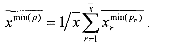
- Average minimum amount of additional packets from previous connections at network arrival instant of packet number r is and of an arbitrary packet
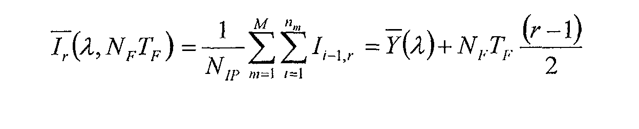
- Mean total inter-arrival time of an arbitrary packet is and for the i th call: and for the r th packet:
Landscapes
- Engineering & Computer Science (AREA)
- Multimedia (AREA)
- Computer Networks & Wireless Communication (AREA)
- Signal Processing (AREA)
- Computer Security & Cryptography (AREA)
- Data Exchanges In Wide-Area Networks (AREA)
Abstract
Description
A packet is a piece of data consisting of a header and a payload information. Packetizing is the process of decomposing data into a set of (small) packets, where the header is used to store information for reconstruction, e.g. a sequence number.
A data channel is a connection between two network units that is able to transport data. Delay is the time between sending and receiving a packet. Delay jitter is the variation in delay. Packet loss is an infinite delay.
A more sophisticated algorithm is to monitor delay and/or delay variation and adapt play-out time accordingly, called jitter adaptation. An application might then slow down play-out when delay increases to avoid loss and speed up play-out when delay decreases to reduce delay.
- providing of at least one estimation method based on at least one characteristic value concerning data connections of the kind intended for,
- gathering measurements of at least one value characterizing the data connection,
- evaluating a de-jittering delay for the data connection by predicted parameters taking into account the at least one provided value and the at least one gathered value,
- delaying and converting the data packets following the evaluated de-jittering delay.
The invention also relates to an output unit, a terminal, and computer program products for a terminal and for an output unit.
The present invention uses a continuous optimization for adapting the parameters of a conversion method. This optimization decomposes into three steps. Continuously gathering network observations, i.e. quality of service measurements, deriving a statistical prediction from these network observations, and adapting the parameters of the conversion method according to said prediction.
The terminal B4 has an output unit B3. This output unit B3 is connected via a data channel B2 with a network B1. The telephone terminal B5 is as well connected with the network B1 via a data channel B2.
In the illustrated configuration the output stream data carries data from packets 1,2,3,4,5, the buffer queue A2 stores packets 6, 7, 8, 9, 10, 11, 12, 13, and the input channel data A5 consists of the packets 15, 14, 16, 17, 19, 18, 20.
The network might have additional characteristics, e.g. an asserted delay bound that should be taken into account when implementing the described functionality. In further, it is assumed that there is no packet loss. In case of packet loss additional strategies have to be considered beside buffering, e.g., reconstruction of packet information on the application layer or depending if network resources and time are available an additional request for re-transmission.
The "Network" is associated with the "Converter" by "Data channel" and the "Application" is associated with the "Converter" by "Data stream". The "Converter" is extended by the "Control".
"Channel" provides the two methods "End" and "Fetch". "Stream" provides the two methods "Append" and "Read". "PriorityQueue" provides four methods "Add", "Get", "IsEmpty", and "Size". "Estimation" provides the two methods "Measure" and "Predict".
The diagram shows an architecture for streamed data reconstruction. This architecture has a framework character. It is designed for illustration purposes. It allows to substitute the estimation and to simplify the description by abstraction. An architecture of a realization is influenced by the complete product design.
The architecture consists of three abstract data types, a channel, a stream and a priority queue, as well as two processes, "Receive" and "Stream".
The priority queue is chosen to illustrate the abstract buffering mechanism. It is not necessary to use abstract data types. For instance, a often used technique instead of a priority queue is a straight forward array implementation of a buffer queue.
The method "Append" of the data type "Stream" appends the argument to the end of this stream. The method "Read" reads the head of this stream (destructive).
The method "Add" of the data type "PriorityQueue" enters the argument into this priority queue.
The method "Get" returns the least element of this priority queue. The method "isEmpty" returns the Boolean true if this priority queue contains no element, the Boolean false otherwise. The method "Size" returns the number of elements contained in this priority queue.
The method "Measure" of the class "Estimation" collects network performance information and updates network characteristics accordingly. The method "Predict" returns values for controlling the behavior of the two processes.
The two processes are controlled by the class "Estimation" that measures network behavior and derives network performance predictions. The two processes "Receive" and "Stream" use this prediction in order to adapt their behavior, e.g. the use of the buffer queue or the stream speed etc.
The abstract notation for the program consists of a declaration part for variables and types, labeled by 'DECLARATION' and an implementation part labeled by 'IMPLEMENTATION'. The variable declaration part consists of three objects:
- a data type "Channel", framed by 'DATA TYPE Channel' and 'END DATA TYPE Channel',
- a data type "Stream", framed by 'DATA TYPE Stream' and 'END DATA TYPE Stream',
- a data type "PriorityQueue", framed by 'DATA TYPE PriorityQueue' and 'END DATA TYPE PriorityQueue'.
- a process "Receive", framed by 'PROCESS Receive' and 'END PROCESS Receive', and
- a process "Stream" framed by 'PROCESS Stream' and 'END PROCESS Stream',
- a class "Estimation", framed by 'CLASS Estimation' and 'END CLASS Estimation'.
- a method "End", returning the Boolean true if the input packet sequence ends, and
- a method "Fetch", returning the next arrived packet.
- a method "Append", adding a data element at the end of this stream, and
- a method "Read", returning the next element of the stream.
- a method "Add", adding a packet to this priority queue
- a method "Get", returning and removing the packet with the least element, i.e. the packet with the least number, from this priority queue,
- a method "IsEmpty", returning the Boolean true if the priority queue contains no packet,
- a method "Size", returning an integer, the number of packets contained in this priority queue.
Hence, the process iterative reads a packet from the input channel, update the performance statistic of the network and buffers the packet, until the last packet is arrived.
The second while loop, framed by 'WHILE' and 'END WHILE', with the terminating condition 'NOT Buffer.isEmpty()' and a body consisting of the statement sequence 'Output.Append(Buffer.Get())'; 'DELAY(DelayTime)', empties the buffer and serves the stream continuously with a homogenous by the Estimation predicted delay.
The latter two loops are iterated until the complete stream is reconstructed.
Furthermore, the class "Estimation" consists of a set of variables for the statistical observations and two methods,
- a method "Measure" that updates the network characteristics by observed events, here a packet arrival, and
- a method "Predict", that returns parameters for the conversion, here BufferSize and DelayTime, based on gathered network characteristics.
- A method "Measure" that updates the mean delay T by an observed packet delay t, as well as the decrement of the number of remaining packets R and
- A method "Predict", that returns parameters for the conversion, buffer size B and delay time (the reciprocal of the sample rate), based on gathered network characteristics.
The diagrams are connected via three dashed arrows showing a path of packet P(2,1).
The horizontal double arrows A2 shows a time interval until packet P(2,1) arrives The horizontal arrow W2,1 shows a waiting time interval of packet P(2,1). A horizontal arrow Nstag TS shows a service time interval of P(2,1) , and a horizontal arrow d2,1 shows a delay of packet P(2,1) . Assumptions for the shown scenario are identical encoding (e.g. Voice Activity Detection or not) and packetisation of the arriving calls, with no time stamps and available packet sequence numbers. Negative-exponentially distributed connection inter-arrival time A2 is assumed at the encoder.
Shown in diagram O2 a packet-based network delays discontinuously packets with a deterministic service time NstagTS . No priorities, no re-transmission, no overtaking, no change in routing, only real-time traffic, and no disturbing data traffic is assumed.
The packet P(2,1) is traced through the described scenario. At the sender this packet is created after the time A2 starting from the creation event of the preceding packet P(1,1) . When the first packet is processed the packet P(2,1) enters the network. There it waits for the time W2,1 . When the waiting time is passed the network transports the packet within time Nstag TS to the receiver. At the receiver it is buffered for a time Tjit and decoded within a time Tdec .
For most packet networks the assumption that each packet is delayed equally is wrong. But one could approximate the real delay with the mean delay of the already transmitted packets instead. The mean delay T(n) for n transmitted packets each having its own delay ti is the sum delay t1 + t2 + ... + tn divided by n. For calculation T(n+1) consider T(n+1)=(t1 +t2 +...+tn +tn + 1)/(n+1)=((t1 +t2 +...+tn)+tn + 1)/(n+1), but (t1 +t2 +...+tn) = n * T(n). Hence T(n+1) = (n * T(n) + tn + 1) / (n+1).
The above discussion is illustrated as an implementation of class 'Estimation' shown in Figure 6.
The statistical model can be enhanced by observable properties of the network like packet routing, traffic, or network topology, and of the stream content itself, like length pauses and talk spurts in the case of voice data streams, as well as past transmissions or even past connections.
The following section describes a more complex application for the special case of reducing delay jitter for a packetized voice network, with minimal delay, i.e., small queues in the context and with the assumptions of Figure 6. A set of recursive measurement and prediction equations, based on multiple probabilistic models is developed illustrating the claimed method.
The main assumptions are a constant inter-arrival time for the packets at the network during active voice, but no constant inter-departure time when arriving at the receiver.
For the detailed description the following notations are used for the encoding and packetisation delay factors
- frame size TF
- encoder processing time Tenc
- look ahead TLA
- NF code words per packet
- inter-packet time NF TF
- decoder processing delay Tdec
- inter-packet time NFTF
- service time per node and packet TS
- number of traversed nodes Nstag
- total service time NstagTS
- statistical waiting time WN
- the maximum end-to-end delay is dE2E ,
- the number of traversed nodes Nstag ,
- the service time per node TS ,
- the mean number of created packets per call is
x calculated out of the mean call holding time - calls per second (dependent on daytime)
- packet frame length TF
- number of packets per frame NF
- Number of overall competing connections NIP
- Number of route busy periods M
- Number of competing connections per busy period nm
- Mean delay of an arbitrary packet:
d (Nstag,Ts,x ,λ,NFTF ) - Mean absolute relative delay of an arbitrary packet:
Δd (Nstag,Ts,x ,λ,NFTF ) - Mean delay of the r th packet
d r (Nstag,Ts,x ,λ,NFTF ) - Average number of cumulative network packet arrivals at network arrival instant of packet
number r:
and of an arbitrary packet:


- Average relative number of cumulative network packet arrivals at network arrival instant of
packet number r.
and of an arbitrary packet:
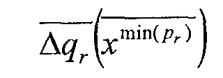

- Average minimum amount of additional packets from previous connections at network
arrival time instant of packet number r.
and of an arbitrary packet:


- Average minimum amount of additional packets from calls arriving after the observed
connection until network arrival instant of packet number r.
and an arbitrary network packet arrival instant:


- Mean total inter-arrival time of an arbitrary packet:
the i th call:
 and the r th packet:

- Mean value of NIP Erlang-(i-1) distributed time intervals:
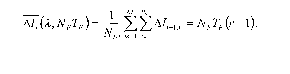
Y (λ) - Mean values of the relative absolute total inter-arrival time of an arbitrary packet:
the ith call:
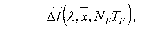 and the r th packet:

- Packet arrival instants at the decoder: tD r
- Delay of the r th packet: dr
- Reference packet number ref, which is the number of the first arriving packet
- QoS dejittering delay: Tjit
- Packet loss probability: Ploss
- Maximum allowed end-to-end delay: dE2E
- Number of packets per active voice period xk m+i
- Number of packet losses xloss
- Number of overlong delays xE2E
- Coefficient of variation c
- Hypo-exponential Process FD (t;t1,t2 ) with mean values t 1 and t 2.
- Hyper-exponential Process FD (t,p,t 1,t 2) with the mean values t 1,2 and probability p.
Ii -1 describes the total inter-arrival period from the begin of route busy period m until network arrival instant of the r th packet of the i th connection.
The total number of network packet arrivals from the beginning of the busy period m until service beginning of the observed packet is named qk
ΔIi -1, r denotes the relative total inter-arrival time of the r th packet produced from the i th call. The negative-exponentially distributed encoder inter-arrival time of the lth connection is named Ak
This prediction is based on gathered the decoder packet arrival instants tD
There are two quality of service bounds considered, namely, the packet loss restriction Pr└d > d min + T jit ┘ < Ploss and the delay restriction d max + Tjit < dE 2 E .
- the maximum end-to-end delay dE 2 E
- the highest tolerated probability for packet loss due to jitter problems Ploss
- the number of traversed nodes Nstag
- the service time per node TS
- the mean number of created packets per call
x calculated out of the mean call holding time - calls per second (dependent on daytime)
- packet frame length TF
- number of packets per frame NF for
- the (initial) service time NstagTS
- the packet length NF TF
- the initial mean delay of an arbitrary packet
d (0) :=d (Nstag,Ts,x ,λ,NFTF ) - the initial mean absolute relative delay of an arbitrary packet
Δd (0) :=Δd (Nstag,Ts,x ,λ,NFTF ) - the initial coefficient of variation c (0) =
Δd (0) /d (0) to determine the initial delay probability function.
For the shown statistical description it is necessary to count the number packets per active voice period xk
The route length Nstag and the service time NstagTS as well as the mean delay



The result is used to adapt the stream output respectively by the maximum relative delay: Δd (q) / max := d (q) / max - d min = d (q) / max - NstagTS and determine T (q) / jit according to Δd (q) / max =:T (q) / jit ≤ dE2E-d (q) / max during a silence period.
The waiting time summarises the complete busy period until packet number km + i,. starts being serviced and reduces it with the time interval Ii- 1, r : Wk
The total inter-arrival time of the rth packet of the i th call is Ii- 1, r = Y i-1 + (r-1)NFTF
The relative total arrival time of the rth packet of the i th call is ΔI i-1, r = (r-1)NFTF
The number of l= 1, ..., j and j=1, ... competing packet arrivals between i th connection arrival instant and network arrival instant of packet r from connection I is
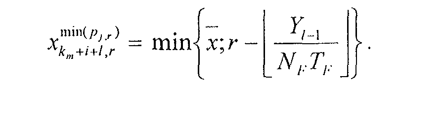

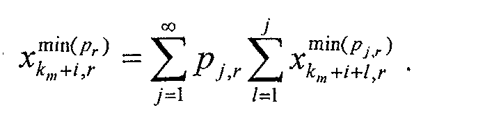



The mean absolute relative delay of an arbitrary packet









Claims (11)
- Method for reconstructing non-continuous packetized data of a continuous data stream (A5) like streamed media, voice, audio, or video from a data connection into a continuous data stream (A6) at the receiving point (B3, B4, B5) of a packet-based network (B1), comprising the steps ofproviding of at least one estimation method (Figure 4: "Estimation") based on at least one characteristic value (Figure 5,6: "Estimation") concerning data connections (A3, B2) of the kind intended for,gathering measurements of at least one value (Figure 5,6: "Estimation") characterizing the data connection,evaluating a de-jittering delay for the data connection by predicted parameters (Figure 5,6: "Estimation") taking into account the at least one provided value and the at least one gathered value,delaying and converting the data packets following the evaluated de-jittering delay (Figure 3, 4; Figure 5: "Estimation", "Stream", "Receive").
- Output unit (B3) for reconstructing non-continuous packetized data (A5) of a continuous data stream like streamed media, voice, audio, or video into a continuous data stream (A6), comprising means forproviding of at least one estimation method (Figure 4: "Estimation") based on at least one characteristic value (Figure 5,6: "Estimation") concerning data connections (A3, B2) of the kind intended for,gathering measurements of at least one value (Figure 5,6: "Estimation") characterizing the data connection,evaluating a de-jittering delay for the data connection by predicted parameters (Figure 5,6: "Estimation") taking into account the at least one provided value and the at least one gathered value,delaying and converting the data packets following the evaluated de-jittering delay (Figure 3, 4; Figure 5: "Estimation", "Stream", "Receive").
- Terminal with output unit for reconstructing non-continuous packetized data of a continuous data stream like streamed media, voice, audio, or video) into a continuous packet data stream, comprising means forproviding of at least one estimation method (Figure 4: "Estimation") based on at least one characteristic value (Figure 5,6: "Estimation") concerning data connections (A3, B2) of the kind intended for,gathering measurements of at least one value (Figure 5,6: "Estimation") characterizing the data connection,evaluating a de-jittering delay for the data connection by predicted parameters (Figure 5,6: "Estimation") taking into account the at least one provided value and the at least one gathered value,delaying and converting the data packets following the evaluated de-jittering delay (Figure 3, 4; Figure 5: "Estimation", "Stream", "Receive").
- A computer program product including software code portions for performing steps of Claim 1 for a terminal (Figure 5).
- A computer program product including software code portions for performing steps of Claim 1 for an output unit (Figure 5).
- A method according to in Claim 1 characterized by measuring the packet inter-arrival times (Figure 5,6, class "Estimation").
- A method according to in Claim 1 characterized by calculating the variation of the packet inter-arrival times (Figure 5, class "Estimation").
- A method according to in Claim 1 characterized by using a network description and routing information for predicting said parameters.
- A method according to in Claim 1 characterized by performing an initialization based of measurements of at least one value characterizing the data connection gathered by the first transmitted packets.
- A method according to in Claim 1 characterized by performing an initialization based of measurements of at least one value characterizing the data connection gathered by previous transmissions.
- A method according to in Claim 1 characterized by performing an initialization based of measurements of at least one value characterizing the data connection gathered by previous connections.
Priority Applications (2)
| Application Number | Priority Date | Filing Date | Title |
|---|---|---|---|
| EP02360111A EP1349342A1 (en) | 2002-03-28 | 2002-03-28 | A method, an output unit, a terminal, and computer program products for reconstructing a continuous data stream at the receiving point of a packet network |
| US10/397,168 US7889653B2 (en) | 2002-03-28 | 2003-03-27 | Method, output unit, and terminal for reconstructing non-continuous packetized data |
Applications Claiming Priority (1)
| Application Number | Priority Date | Filing Date | Title |
|---|---|---|---|
| EP02360111A EP1349342A1 (en) | 2002-03-28 | 2002-03-28 | A method, an output unit, a terminal, and computer program products for reconstructing a continuous data stream at the receiving point of a packet network |
Publications (1)
| Publication Number | Publication Date |
|---|---|
| EP1349342A1 true EP1349342A1 (en) | 2003-10-01 |
Family
ID=27798944
Family Applications (1)
| Application Number | Title | Priority Date | Filing Date |
|---|---|---|---|
| EP02360111A Withdrawn EP1349342A1 (en) | 2002-03-28 | 2002-03-28 | A method, an output unit, a terminal, and computer program products for reconstructing a continuous data stream at the receiving point of a packet network |
Country Status (2)
| Country | Link |
|---|---|
| US (1) | US7889653B2 (en) |
| EP (1) | EP1349342A1 (en) |
Cited By (1)
| Publication number | Priority date | Publication date | Assignee | Title |
|---|---|---|---|---|
| EP1678577A4 (en) * | 2003-10-29 | 2007-05-30 | Nokia Corp | METHOD AND APPARATUS FOR EASY ADAPTIVE MANAGEMENT OF PACKETS HAVING TIME ORDINARY CONTENT IN A RECEPTION TERMINAL |
Families Citing this family (5)
| Publication number | Priority date | Publication date | Assignee | Title |
|---|---|---|---|---|
| US7822073B2 (en) * | 2005-11-03 | 2010-10-26 | George Mason Intellectual Properties, Inc. | Packet flow side channel |
| US9236039B2 (en) | 2013-03-04 | 2016-01-12 | Empire Technology Development Llc | Virtual instrument playing scheme |
| US9794260B2 (en) * | 2015-08-10 | 2017-10-17 | Yoti Ltd | Liveness detection |
| WO2018047738A1 (en) * | 2016-09-08 | 2018-03-15 | 日本電気株式会社 | Base station device, wireless communication control system, wireless communication control method, and recording medium having base station control program stored therein |
| US11336683B2 (en) * | 2019-10-16 | 2022-05-17 | Citrix Systems, Inc. | Systems and methods for preventing replay attacks |
Citations (2)
| Publication number | Priority date | Publication date | Assignee | Title |
|---|---|---|---|---|
| WO2001033787A1 (en) * | 1999-10-29 | 2001-05-10 | Array Telecom Corporation | Method, system, and computer program product for managing jitter |
| US6259677B1 (en) * | 1998-09-30 | 2001-07-10 | Cisco Technology, Inc. | Clock synchronization and dynamic jitter management for voice over IP and real-time data |
Family Cites Families (6)
| Publication number | Priority date | Publication date | Assignee | Title |
|---|---|---|---|---|
| US4771250A (en) * | 1987-08-13 | 1988-09-13 | United States Of America As Represented By The Administrator, National Aeronautics And Space Adminstration | Digital phase-lock loop having an estimator and predictor of error |
| US5623483A (en) * | 1995-05-11 | 1997-04-22 | Lucent Technologies Inc. | Synchronization system for networked multimedia streams |
| US6304551B1 (en) * | 1997-03-21 | 2001-10-16 | Nec Usa, Inc. | Real-time estimation and dynamic renegotiation of UPC values for arbitrary traffic sources in ATM networks |
| DE60104353T2 (en) * | 2000-04-07 | 2005-07-21 | Ntt Docomo Inc. | Method and device for reducing the delay jitter in data transmission |
| US7177271B2 (en) * | 2001-09-21 | 2007-02-13 | Microsoft Corporation | Method and system for managing admission to a network |
| US7079486B2 (en) * | 2002-02-13 | 2006-07-18 | Agere Systems Inc. | Adaptive threshold based jitter buffer management for packetized data |
-
2002
- 2002-03-28 EP EP02360111A patent/EP1349342A1/en not_active Withdrawn
-
2003
- 2003-03-27 US US10/397,168 patent/US7889653B2/en not_active Expired - Fee Related
Patent Citations (2)
| Publication number | Priority date | Publication date | Assignee | Title |
|---|---|---|---|---|
| US6259677B1 (en) * | 1998-09-30 | 2001-07-10 | Cisco Technology, Inc. | Clock synchronization and dynamic jitter management for voice over IP and real-time data |
| WO2001033787A1 (en) * | 1999-10-29 | 2001-05-10 | Array Telecom Corporation | Method, system, and computer program product for managing jitter |
Non-Patent Citations (1)
| Title |
|---|
| AGRAWAL P ET AL: "Use of statistical methods to reduce delays for media playback buffering", MULTIMEDIA COMPUTING AND SYSTEMS, 1998. PROCEEDINGS. IEEE INTERNATIONAL CONFERENCE ON AUSTIN, TX, USA 28 JUNE-1 JULY 1998, LOS ALAMITOS, CA, USA,IEEE COMPUT. SOC, US, 28 June 1998 (1998-06-28), pages 259 - 263, XP010291583, ISBN: 0-8186-8557-3 * |
Cited By (2)
| Publication number | Priority date | Publication date | Assignee | Title |
|---|---|---|---|---|
| EP1678577A4 (en) * | 2003-10-29 | 2007-05-30 | Nokia Corp | METHOD AND APPARATUS FOR EASY ADAPTIVE MANAGEMENT OF PACKETS HAVING TIME ORDINARY CONTENT IN A RECEPTION TERMINAL |
| US7457282B2 (en) | 2003-10-29 | 2008-11-25 | Nokia Corporation | Method and apparatus providing smooth adaptive management of packets containing time-ordered content at a receiving terminal |
Also Published As
| Publication number | Publication date |
|---|---|
| US7889653B2 (en) | 2011-02-15 |
| US20030185246A1 (en) | 2003-10-02 |
Similar Documents
| Publication | Publication Date | Title |
|---|---|---|
| Jha et al. | Engineering Internet QoS | |
| Little et al. | Multimedia synchronization protocols for broadband integrated services | |
| Aras et al. | Real-time communication in packet-switched networks | |
| Salehi et al. | Supporting stored video: Reducing rate variability and end-to-end resource requirements through optimal smoothing | |
| Ramanathan et al. | Feedback techniques for intra-media continuity and inter-media synchronization in distributed multimedia systems | |
| US8769591B2 (en) | Fast channel change on a bandwidth constrained network | |
| US7551647B2 (en) | System and method for clock synchronization over packet-switched networks | |
| AU2008330261B2 (en) | Play-out delay estimation | |
| Ishibashi et al. | A comparative survey of synchronization algorithms for continuous media in network environments | |
| TW200536310A (en) | Packet scheduling for multimedia streaming based on priorities and buffer status | |
| WO2001033787A1 (en) | Method, system, and computer program product for managing jitter | |
| Xie et al. | Adaptive multimedia synchronization in a teleconference system | |
| Anderson | Meta-scheduling for distributed continuous media | |
| Gibbon et al. | The use of network delay estimation for multimedia data retrieval | |
| Rexford et al. | A smoothing proxy service for variable-bit-rate streaming video | |
| US7889653B2 (en) | Method, output unit, and terminal for reconstructing non-continuous packetized data | |
| Li et al. | Synchronization in real time multimedia data delivery | |
| JP2002319971A (en) | Packet data relay device and distribution device | |
| Feng | Applications and extensions of the imprecise-computation model | |
| Huo et al. | Network adapted selective frame-dropping algorithm for streaming media | |
| Eleftheriadis et al. | Architecture and algorithms of the Xphone multimedia communication system | |
| Chen | Simulation and analysis of quality of service parameters in IP networks with video traffic | |
| Class | Synchronization issues in distributed applications: Definitions, problems, and quality of synchronization | |
| Kim et al. | A TMO-based software architecture for distributed real-time multimedia processing | |
| Baldi et al. | Distortion-aware video communication with pipeline forwarding |
Legal Events
| Date | Code | Title | Description |
|---|---|---|---|
| PUAI | Public reference made under article 153(3) epc to a published international application that has entered the european phase |
Free format text: ORIGINAL CODE: 0009012 |
|
| 17P | Request for examination filed |
Effective date: 20021128 |
|
| AK | Designated contracting states |
Kind code of ref document: A1 Designated state(s): AT BE CH CY DE DK ES FI FR GB GR IE IT LI LU MC NL PT SE TR |
|
| AX | Request for extension of the european patent |
Extension state: AL LT LV MK RO SI |
|
| 17Q | First examination report despatched |
Effective date: 20031121 |
|
| AKX | Designation fees paid |
Designated state(s): AT BE CH CY DE DK ES FI FR GB GR IE IT LI LU MC NL PT SE TR |
|
| 17Q | First examination report despatched |
Effective date: 20031121 |
|
| RAP1 | Party data changed (applicant data changed or rights of an application transferred) |
Owner name: ALCATEL LUCENT |
|
| STAA | Information on the status of an ep patent application or granted ep patent |
Free format text: STATUS: THE APPLICATION IS DEEMED TO BE WITHDRAWN |
|
| 18D | Application deemed to be withdrawn |
Effective date: 20091001 |