EP1349304A2 - Method for generating channel quality feedback information in a two transmit N-receive antenna system - Google Patents
Method for generating channel quality feedback information in a two transmit N-receive antenna system Download PDFInfo
- Publication number
- EP1349304A2 EP1349304A2 EP03251637A EP03251637A EP1349304A2 EP 1349304 A2 EP1349304 A2 EP 1349304A2 EP 03251637 A EP03251637 A EP 03251637A EP 03251637 A EP03251637 A EP 03251637A EP 1349304 A2 EP1349304 A2 EP 1349304A2
- Authority
- EP
- European Patent Office
- Prior art keywords
- channel
- elements
- matrix
- eigenvectors
- quantized
- Prior art date
- Legal status (The legal status is an assumption and is not a legal conclusion. Google has not performed a legal analysis and makes no representation as to the accuracy of the status listed.)
- Granted
Links
Images
Classifications
-
- H—ELECTRICITY
- H04—ELECTRIC COMMUNICATION TECHNIQUE
- H04B—TRANSMISSION
- H04B7/00—Radio transmission systems, i.e. using radiation field
- H04B7/02—Diversity systems; Multi-antenna system, i.e. transmission or reception using multiple antennas
-
- H—ELECTRICITY
- H04—ELECTRIC COMMUNICATION TECHNIQUE
- H04B—TRANSMISSION
- H04B7/00—Radio transmission systems, i.e. using radiation field
- H04B7/02—Diversity systems; Multi-antenna system, i.e. transmission or reception using multiple antennas
- H04B7/04—Diversity systems; Multi-antenna system, i.e. transmission or reception using multiple antennas using two or more spaced independent antennas
- H04B7/06—Diversity systems; Multi-antenna system, i.e. transmission or reception using multiple antennas using two or more spaced independent antennas at the transmitting station
- H04B7/0613—Diversity systems; Multi-antenna system, i.e. transmission or reception using multiple antennas using two or more spaced independent antennas at the transmitting station using simultaneous transmission
- H04B7/0615—Diversity systems; Multi-antenna system, i.e. transmission or reception using multiple antennas using two or more spaced independent antennas at the transmitting station using simultaneous transmission of weighted versions of same signal
- H04B7/0619—Diversity systems; Multi-antenna system, i.e. transmission or reception using multiple antennas using two or more spaced independent antennas at the transmitting station using simultaneous transmission of weighted versions of same signal using feedback from receiving side
- H04B7/0621—Feedback content
- H04B7/0634—Antenna weights or vector/matrix coefficients
-
- H—ELECTRICITY
- H04—ELECTRIC COMMUNICATION TECHNIQUE
- H04B—TRANSMISSION
- H04B7/00—Radio transmission systems, i.e. using radiation field
- H04B7/02—Diversity systems; Multi-antenna system, i.e. transmission or reception using multiple antennas
- H04B7/04—Diversity systems; Multi-antenna system, i.e. transmission or reception using multiple antennas using two or more spaced independent antennas
- H04B7/06—Diversity systems; Multi-antenna system, i.e. transmission or reception using multiple antennas using two or more spaced independent antennas at the transmitting station
- H04B7/0602—Diversity systems; Multi-antenna system, i.e. transmission or reception using multiple antennas using two or more spaced independent antennas at the transmitting station using antenna switching
- H04B7/0608—Antenna selection according to transmission parameters
- H04B7/061—Antenna selection according to transmission parameters using feedback from receiving side
-
- H—ELECTRICITY
- H04—ELECTRIC COMMUNICATION TECHNIQUE
- H04B—TRANSMISSION
- H04B7/00—Radio transmission systems, i.e. using radiation field
- H04B7/02—Diversity systems; Multi-antenna system, i.e. transmission or reception using multiple antennas
- H04B7/04—Diversity systems; Multi-antenna system, i.e. transmission or reception using multiple antennas using two or more spaced independent antennas
- H04B7/06—Diversity systems; Multi-antenna system, i.e. transmission or reception using multiple antennas using two or more spaced independent antennas at the transmitting station
- H04B7/0613—Diversity systems; Multi-antenna system, i.e. transmission or reception using multiple antennas using two or more spaced independent antennas at the transmitting station using simultaneous transmission
- H04B7/0615—Diversity systems; Multi-antenna system, i.e. transmission or reception using multiple antennas using two or more spaced independent antennas at the transmitting station using simultaneous transmission of weighted versions of same signal
- H04B7/0619—Diversity systems; Multi-antenna system, i.e. transmission or reception using multiple antennas using two or more spaced independent antennas at the transmitting station using simultaneous transmission of weighted versions of same signal using feedback from receiving side
- H04B7/0636—Feedback format
-
- H—ELECTRICITY
- H04—ELECTRIC COMMUNICATION TECHNIQUE
- H04B—TRANSMISSION
- H04B7/00—Radio transmission systems, i.e. using radiation field
- H04B7/02—Diversity systems; Multi-antenna system, i.e. transmission or reception using multiple antennas
- H04B7/04—Diversity systems; Multi-antenna system, i.e. transmission or reception using multiple antennas using two or more spaced independent antennas
- H04B7/06—Diversity systems; Multi-antenna system, i.e. transmission or reception using multiple antennas using two or more spaced independent antennas at the transmitting station
- H04B7/0613—Diversity systems; Multi-antenna system, i.e. transmission or reception using multiple antennas using two or more spaced independent antennas at the transmitting station using simultaneous transmission
- H04B7/0667—Diversity systems; Multi-antenna system, i.e. transmission or reception using multiple antennas using two or more spaced independent antennas at the transmitting station using simultaneous transmission of delayed versions of same signal
- H04B7/0673—Diversity systems; Multi-antenna system, i.e. transmission or reception using multiple antennas using two or more spaced independent antennas at the transmitting station using simultaneous transmission of delayed versions of same signal using feedback from receiving side
Definitions
- the present invention relates generally to antennas in communication systems and more particularly to antenna systems in wireless communication systems.
- Antennas are part of some of the more critical components of a communication system, and in particular, wireless communication systems.
- communication signals that are transmitted by antennas over traffic channels and signaling channels will at some point propagate through the air and be received by other antennas.
- the traffic channels are communication channels through which users of the wireless communication system convey (i.e., transmit and/or receive) communication signals to each other.
- the communication signals typically carry information being conveyed between users.
- the signaling channels are communication channels through which signals that facilitate the control, maintenance and management of the communication system are conveyed.
- the signaling signals are typically transmitted by system equipment and user equipment.
- System equipment are various communication equipment owned, controlled and operated by a system operator or provider. Examples of system operators include local telephone companies and Internet service providers.
- User equipment are equipment that are typically owned and operated by users of the communication system. Examples of user equipment include cellular phones, wireless personal computers and pagers.
- the communication signals propagate through the air, they are adversely affected by various anomalies that distort such signals and cause part or all of the information being carried by said signals to be received erroneously.
- the quality of the communication channels can greatly affect the communication system's throughput.
- the throughput is the amount of information that is received without any errors for a given period of time.
- the various anomalies of a communication channel can adversely affect any one or all of a signal's parameters; some of these parameters include signal amplitude, signal phase, signal frequency.
- the signals are transmitted by transmit antennas and received by receive antennas. It should be noted that the antennas are often designed to operate as both transmit and receive antennas.
- communication systems often employ a feedback technique where a receive antenna transmits channel quality feedback information to a transmit antenna allowing the transmit antenna to modify, in some fashion, one or more of the signal's parameters.
- the channel quality feedback information is information about how transmitted signals are affected by the communication channel through which they have propagated.
- the signals propagating through the communication channel can therefore be manipulated so as to be less vulnerable to the various channel anomalies; thus the adverse effects of the channel are effectively reduced thus increasing throughput.
- the communication system can use more than one transmit antenna and more than one receive antenna for the same or different signals.
- the signals carry the same information, they may have different parameters. Therefore, the signals may be affected differently by the communication channel. Even when the signals carry the same information and have the same parameters, they may still be affected differently by the communication channel.
- One feedback technique used by many communication systems is to have the receive antennas transmit channel quality feedback information to the transmit antenna informing the transmit antennas about the quality of the transmitted signals. The parameters of the transmitted signal least adversely affected by the communication channel is then used in ensuing transmissions by the transmit antennas in an effort to improve the quality of the received signals.
- Another technique is to pre-distort the transmit signals based on the channel quality feedback information received by the transmit antennas from the receive antennas.
- the pre-distortion compensates for the anomalies that the transmitted signals experience as they propagate through the communication channel.
- the channel quality feedback information may be based on measurements of previously transmitted signals or measurements of various channel parameters from signals transmitted over the signaling channel.
- a signal that is typically transmitted over the signaling channel and measured by the system is the pilot signal.
- Many wireless communication systems have a pilot signal that, among other purposes, serves to signal the presence of system equipment.
- Another technique is to measure the amount of energy contained in the two receive signals and send that information back to the transmit antennas.
- the parameters of the signal having the higher measured energy will be used for the next transmission.
- a rather brute force method is used to determine which set of signal parameters will allow a transmitted signal to be relatively less adversely affected by the communication channel.
- These brute force methods require a relatively large amount of information to be fed back to the transmit antennas.
- the channel quality feedback information is continuously being sent back to the transmit antennas.
- Many communication systems have limited bandwidth for their signaling channels through which other critical information are conveyed. It may not, therefore, be practical to send all of the feedback information.
- the communication channel is a continually varying dynamic system, it may not be possible to efficiently and quickly modify the transmit signal to reduce its vulnerability to the channel anomalies.
- the communication channel can be modeled as an Eigenspace represented by an eigenvector matrix whose elements are complex numbers each of which is a basic unit that represents one or more measured parameters of the communication channel.
- the measured parameters of the channel include, for example, the effect of the channel on a signal's amplitude, the effect of the channel on a signal's phase and the effect of the channel on a signal's frequency.
- the measured channel parameters are also called channel parameters. For example suppose a signal is transmitted with an amplitude of 0 db, but such signal is received with a measured amplitude of-3 dB. The channel parameter for amplitude is thus -3 dB.
- a channel parameter matrix can be generated from measured channel parameters.
- a channel matrix can thus be formed from measurements of channel parameters. Again suppose, there are two transmit antennas ( T 1 and T 2 ) and two receive antennas ( R 1 and R 2 ).
- the channel parameter measurement at receive antenna R 1 due to a signal transmitted by transmit antenna T 1 is designated h 11 .
- the channel parameter measurement at receive antenna R 2 due to a signal transmitted by transmit antenna T 1 is designated h 12 .
- the channel parameter measurement at receive antenna R 1 due to a signal transmitted by transmit antenna T 2 is designated h 21 .
- the channel parameter measurement at receive antenna R 2 due to a signal transmitted by transmit antenna T 2 is designated h 22 .
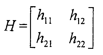
- the measured channel parameters are elements of the channel matrix H , where: and where h 11 , h 12 , h 21 and h 22 are complex numbers having complex conjugates h 11 *, h 12 *, h 21 * and h 22 *.
- a channel correlation matrix is obtained by performing a Hermitian operation on the channel matrix and premultiplying the channel matrix with this Hermitian matrix.
- the Hermitian operation is a well known matrix mathematical conversion in which all of the elements of the matrix are changed to their complex conjugates and the transpose of the complex conjugate matrix is performed.
- the channel correlation matrix is designated as S where S ⁇ H + H.
- the elements of the channel correlation matrix, S are related to eigenvalues and eigenvectors which can be obtained by a well known procedure called an eigenvalue decomposition, Applied Linear Algebra, 2d edition, Ben Noble, James W . Daniel, Prentice Hall Inc., 1977 and 1969, ISBN 0-13-041343-7.
- S ⁇ + where ⁇ is the eigenvector matrix.
- ⁇ is a diagonal eigenvalue matrix whose elements are eigenvalues and ⁇ is a matrix whose columns are eigenvectors.
- channel quality feedback information--represented in terms of the eigenvectors-- is sent or fed back to the transmit antennas to allow these antennas to modify the transmit signals so as to reduce the distortion experienced by these signals.
- the channel quality feedback information in the form of eigenvalues and/or eigenvectors represents a relatively large amount of information that is to be periodically transmitted over band-limited signaling channels of the communication system. Further, many times some of the channel information being transmitted in the form of eigenvalues. and/or eigenvectors are not as accurate in their characterization of the communication channel. In other words, there are certain eigenvalues that more accurately represent the communication channel characteristics than other eigenvalues. Therefore, not only is a great amount of information sent over the already band-limited signaling channel, but many times much of this information is not useful for reducing the anomalous effects of the communication channel.
- the present invention provides a method for generating channel quality feedback information by quantizing eigenvectors that characterize a communication channel.
- the eigenvectors are calculated from an eigenvalue decomposition of a channel correlation matrix.
- the channel correlation matrix is created from a channel matrix formed from measurements of at least one signal parameter of a signal transmitted over the communication channel.
- the elements of the channel correlation matrix are obtained through a Hermitian operation with the channel matrix. Conditional relations between elements of the channel correlation matrix are noted and thus established.
- the channel correlation matrix is expressed in terms of an eigenvector matrix and an eigenvalue matrix.
- the elements of the eigenvector matrix are calculated and certain solutions for the elements of the eigenvector matrix are selected.
- the selected solution result in two relationships between elements of the eigenvector matrix and eigenvalue matrix.
- the first relationship is that elements of the eigenvector matrix can be expressed of terms of other elements of the eigenvector matrix.
- the second relationship is that the elements of the eigenvector matrix can be expressed in terms of the eigenvalues and elements of the channel correlation matrix.
- the eigenvalues are calculated and certain solution are selected based on some conditional relationship between elements of the channel correlation matrix. Because of these relationships in the channel correlation matrix as well as the selected eigenvalues, the elements of the eigenvector matrix are bounded. The boundaries for the elements of the eigenvector matrix are calculated from the two relationships.
- the eigenvectors are then quantized meaning that certain values for the elements of the eigenvectors located within the boundaries are selected in accordance with an algorithm.
- the resulting eigenvectors having quantized and bounded elements, i.e., the bounded quantized eigenvectors are transmitted as channel quality feedback information.
- the quantized bounded eigenvectors contain relatively accurate channel quality feedback information and can be sent using a relatively small amount of information because the elements of these eigenvectors are mathematically related to each other; that is, not all of the bounded quantized eigenvectors need be transmitted over the communication channel thus allowing efficient use of the communication channel.
- the elements of the quantized bounded eigenvectors that are transmitted can be used to determine the eigenvectors that are not transmitted because of the mathematical relationship between the elements the elements of different quantized bounded eigenvectors.
- the present invention provides a method for generating channel quality feedback information by quantizing eigenvectors that characterize a communication channel.
- the eigenvectors are calculated from an eigenvalue decomposition of a channel correlation matrix.
- the channel correlation matrix is created from a channel matrix formed from measurements of at least one signal parameter of a signal transmitted over the communication channel.
- the elements of the channel correlation matrix are obtained through a Hermitian operation with the channel matrix. Conditional relations between elements of the channel correlation matrix are noted and thus established.
- the channel correlation matrix is expressed in terms of an eigenvector matrix and an eigenvalue matrix.
- the elements of the eigenvector matrix are calculated and certain solutions for the elements of the eigenvector matrix are selected.
- the selected solution result in two relationships between elements of the eigenvector matrix and eigenvalue matrix.
- the first relationship is that elements of the eigenvector matrix can be expressed of terms of other elements of the eigenvector matrix.
- the second relationship is that the elements of the eigenvector matrix can be expressed in terms of the eigenvalues and elements of the channel correlation matrix.
- the eigenvalues are calculated and certain solution are selected based on some conditional relationship between elements of the channel correlation matrix. Because of these relationships in the channel correlation matrix as well as the selected eigenvalues, the elements of the eigenvector matrix are bounded. The boundaries for the elements of the eigenvector matrix are calculated from the two relationships.
- the eigenvectors are then quantized meaning that certain values for the elements of the eigenvectors located within the boundaries are selected in accordance with an algorithm.
- the resulting eigenvectors having quantized and bounded elements, i.e., the bounded quantized eigenvectors are transmitted as channel quality feedback information.
- the quantized bounded eigenvectors contain relatively accurate channel quality feedback information and can be sent using a relatively small amount of information because the elements of these eigenvectors are mathematically related to each other; that is, not all of the bounded quantized eigenvectors need be transmitted over the communication channel thus allowing efficient use of the communication channel.
- the elements of the quantized bounded eigenvectors that are transmitted can be used to determine the eigenvectors that are not transmitted because of the mathematical relationship between the elements the elements of different quantized bounded eigenvectors.
- the method of the present invention will be explained in the context of a 2 ⁇ 2 system; that is, a system which contains two transmit antennas and two receive antennas. It will be appreciated by those skilled in the art to which this invention belongs that this invention includes systems with any number of receive antennas. Thus, in general, the method of the present invention is applicable to any 2 ⁇ N system with 2 transmit antennas and N receive antennas where N is any integer equal to 2 or greater.
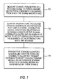
- step 100 receive antennas and associated hardware and software measure at least one parameter of received signals to create a channel matrix, H .
- the at least one signal parameter that is being measured can be, for example, the signal's voltage and the signal's relative phase both of which can be represented by one complex eigenvalue.
- the different measurements become elements of a channel matrix.
- the channel matrix thus contains measurements of parameters of received signals that propagated through the channel.
- the channel correlation matrix, S is then calculated from the channel matrix by the following operation: H + H.
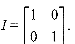
- the channel correlation matrix, S is defined as follows : where the elements of the channel correlation matrix ( a , b, and d ) are complex numbers and the elements of the unitary eigenvector matrix, ⁇ , are eigenvectors representing the voltage and phase channel characteristic of a received signal. It will readily obvious that the elements of the eigenvector matrix can represent signal characteristics other than voltage and phase.
- the eigenvector matrix is represented as follows: e 1 and e 2 are eigenvectors. The values for the elements of the channel correlation matrix are known at this point. Therefore the relationships between elements of the channel correlation matrix are apparent once the channel correlation matrix is calculated using the channel matrix and its Hermitian operator as discussed above.
- the elements within the eigenvectors (i.e., V 11 , V 12 , V 21 and V 22 ) are obtained in terms of the elements of the channel correlation matrix.
- the eigenvector matrix ⁇ that is obtained by performing eigenvalue decomposition on a channel correlation matrix has many solutions. In this invention, a particular solution is selected because of its simplifying effects. The solution in which the eigenvector matrix ⁇ has a particular first relationship between its elements is selected.
- V 2 is the real part of the complex number V 12
- V 11 , V 2 , V 3 are real numbers while V 12 , V 21 are complex numbers.
- the second relationship is that the elements of the eigenvectors can be expressed in terms of the elements of the channel correlation matrix and the eigenvalues.
- 2 + ⁇ 1 - a 2 , and V 12 ( ⁇ 2 - d )
- an expression for ⁇ 1 is obtained based on various conditional relationships between elements of the channel correlation matrix (e.g., conditional relationships between a and b ).
- conditional relationships between a and b e.g., conditional relationships between a and b .
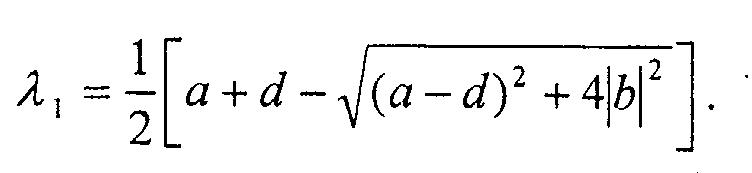
- the eigenvalue ⁇ 1 is calculated using the following equation:
- the eigenvalue ⁇ 1 is calculated using the following equation:
- the elements of the calculated eigenvectors are quantized separately independent of other elements. Because the values of the elements of the eigenvectors are bounded, any value falling within the boundary can be selected for that element.
- One particular algorithm used is to select values that are equidistant from each other along the range of values; this is called the equidistant algorithm.
- Another algorithm that can be used is to select values, which are the center points of adjacent intervals within the boundary, such that the probability a given value falls within a given range is the same. This is called the equi-probability algorithm.
- Another algorithm that can be used is to perform statistical analysis to determine the values, which when transmitted as channel quality feedback information, would least likely be received in error; this is called the statistical algorithm. Because of the relationship between the elements within the eigenvectors, only two real numbers need be transmitted. In the example above, only real numbers V 11 and V 2 need be transmitted since the remaining elements can be determined from these two numbers. Therefore, a relatively lesser amount of channel quality feedback information is transmitted to the transmit antennas; this is especially advantageous for band-limited signaling channels which typically are the communication channels through which these quantized eigenvalues are transmitted. Thus, in the example above only certain elements of the quantized bounded eigenvectors need be transmitted; the other elements can be calculated from the transmitted elements.
- the signaling channels can be part of a wireless communication system or a wireline communication system.
- the quantized bounded eigenvectors representing channel quality feedback information are transmitted over a communication channel to the transmit antennas.
- the communication channel over which such channel quality feedback information is transmitted is preferably a signaling channel.
- the channel quality feedback information can be transmitted over a traffic channel.
- the transmit antennas receiving the channel quality feedback information use such information to modify ensuing transmit signals so as to reduce adverse effects of the channel anomalies experienced by these signals.
- the quantized bounded eigenvectors can be transmitted by system equipment and/or user equipment of the communication system.
- the method of the present invention can reside as a set of instructions (i.e., a computer program, a software package), firmware, digital circuitry, analog circuitry or any combination thereof in system equipment and/or user equipment (e.g., cellular phone, pager, wireless personal computer) of the communication system.
- the communication system can be a wireline or wireless communication system.
Landscapes
- Engineering & Computer Science (AREA)
- Computer Networks & Wireless Communication (AREA)
- Signal Processing (AREA)
- Physics & Mathematics (AREA)
- Mathematical Physics (AREA)
- Radio Transmission System (AREA)
- Mobile Radio Communication Systems (AREA)
Abstract
Description




Claims (8)
- A method of generating channel quality feedback information for a communication channel of a communication system, the method comprising the step of:quantizing eigenvectors having elements and representing channel quality feedback information that is to be transmitted over the communication channel wherethe eigenvectors are calculated from an eigenvalue decomposition that uses a channel correlation matrix, conditional relationships between elements of the channel correlation matrix and an eigenvalue matrix to select certain solutions for the eigenvectors wherebythe selected solutions are bounded eigenvectors whose elements can be expressed in terms of other eigenvector elements, elements of the channel correlation matrix and elements of the eigenvalue matrix andwhere the channel correlation matrix and the eigenvalue matrix are obtained from a channel matrix formed from measurements of channel parameters.
- The method of claim 1 where the step of quantizing eigenvectors comprises the steps of:calculating boundaries of the elements of the selected eigenvectors from the elements of the eigenvector matrix, the elements of the eigenvalue matrix and the elements of the channel correlation matrix; andselecting a value that is within the calculated boundaries in accordance with an algorithm.
- The method of claim 2 where the algorithm is an equidistant algorithm.
- The method of claim 2 where the algorithm is equi-probability algorithm.
- The method of claim 2 where the algorithm is a statistical algorithm.
- The method of claim 1 further comprising the step of transmitting the quantized bounded eigenvectors over the communication channel allowing these eigenvectors to be used to reduce channel anomalies experienced by signals transmitted over the communication channel.
- The method of claim 1 where the communication channel is part of a wireless communication system and where the bounded eigenvectors are calculated and quantized by system equipment of the wireless communication system.
- The method of claim 1 where the communication channel is part of a wireless communication system and where the bounded eigenvectors are calculated and quantized by user equipment of the wireless communication system.
Applications Claiming Priority (2)
| Application Number | Priority Date | Filing Date | Title |
|---|---|---|---|
| US112232 | 2002-03-29 | ||
| US10/112,232 US6847805B2 (en) | 2002-03-29 | 2002-03-29 | Method for closed-loop subspace transmission and reception in a two transmit N-receive antenna system |
Publications (3)
| Publication Number | Publication Date |
|---|---|
| EP1349304A2 true EP1349304A2 (en) | 2003-10-01 |
| EP1349304A3 EP1349304A3 (en) | 2003-10-08 |
| EP1349304B1 EP1349304B1 (en) | 2004-08-04 |
Family
ID=27804429
Family Applications (1)
| Application Number | Title | Priority Date | Filing Date |
|---|---|---|---|
| EP03251637A Expired - Lifetime EP1349304B1 (en) | 2002-03-29 | 2003-03-18 | Method for generating channel quality feedback information in a two transmit N-receive antenna system |
Country Status (5)
| Country | Link |
|---|---|
| US (1) | US6847805B2 (en) |
| EP (1) | EP1349304B1 (en) |
| JP (1) | JP4459544B2 (en) |
| KR (1) | KR100961399B1 (en) |
| DE (1) | DE60300016T2 (en) |
Cited By (3)
| Publication number | Priority date | Publication date | Assignee | Title |
|---|---|---|---|---|
| EP1420529A3 (en) * | 2002-11-13 | 2011-05-11 | Panasonic Corporation | Receiving apparatus, transmitting apparatus, and reception method in mimo system |
| CN101019342B (en) * | 2004-09-10 | 2012-01-18 | 英特尔公司 | Closed-loop transmission beamforming method and system in MIMO system with limited feedback |
| EP1790088A4 (en) * | 2004-08-17 | 2014-04-23 | Lg Electronics Inc | METHOD FOR ESTABLISHING A FAST RETROACTION CHANNEL AND FOR TRANSMITTING INFORMATION IN A WIRELESS COMMUNICATION SYSTEM |
Families Citing this family (26)
| Publication number | Priority date | Publication date | Assignee | Title |
|---|---|---|---|---|
| CN1890895B (en) * | 2003-12-05 | 2010-04-28 | 三星电子株式会社 | Apparatus and method for transmitting data through selected eigenvector in closed loop mimo mobile communication system |
| US8983467B2 (en) * | 2003-12-09 | 2015-03-17 | Lsi Corporation | Method and apparatus for access point selection using channel correlation in a wireless communication system |
| US8204149B2 (en) * | 2003-12-17 | 2012-06-19 | Qualcomm Incorporated | Spatial spreading in a multi-antenna communication system |
| US7336746B2 (en) | 2004-12-09 | 2008-02-26 | Qualcomm Incorporated | Data transmission with spatial spreading in a MIMO communication system |
| US8169889B2 (en) | 2004-02-18 | 2012-05-01 | Qualcomm Incorporated | Transmit diversity and spatial spreading for an OFDM-based multi-antenna communication system |
| US8923785B2 (en) | 2004-05-07 | 2014-12-30 | Qualcomm Incorporated | Continuous beamforming for a MIMO-OFDM system |
| US8285226B2 (en) | 2004-05-07 | 2012-10-09 | Qualcomm Incorporated | Steering diversity for an OFDM-based multi-antenna communication system |
| KR100745688B1 (en) * | 2004-07-09 | 2007-08-03 | 한국전자통신연구원 | Apparatus for encoding and decoding multichannel audio signal and method thereof |
| US7978649B2 (en) | 2004-07-15 | 2011-07-12 | Qualcomm, Incorporated | Unified MIMO transmission and reception |
| US7362822B2 (en) * | 2004-09-08 | 2008-04-22 | Intel Corporation | Recursive reduction of channel state feedback |
| US7539253B2 (en) | 2004-09-10 | 2009-05-26 | Intel Corporation | Interpolation in channel state feedback |
| US7289770B2 (en) * | 2004-09-28 | 2007-10-30 | Intel Corporation | Compact feedback for closed loop MIMO |
| US7236748B2 (en) * | 2004-09-30 | 2007-06-26 | Intel Corporation | Closed loop feedback in MIMO systems |
| US7609780B2 (en) * | 2004-09-30 | 2009-10-27 | Intel Corporation | Method and apparatus for performing sequential closed loop multiple input multiple output (MIMO) |
| US7684761B2 (en) * | 2004-11-04 | 2010-03-23 | Nokia Corporation | Closed-loop signalling method for controlling multiple transmit beams and correspondingly adapted transceiver devices |
| KR100690608B1 (en) * | 2004-12-07 | 2007-03-09 | 엘지전자 주식회사 | How to select the channel of the wireless AW unit |
| JP4681877B2 (en) * | 2004-12-28 | 2011-05-11 | パナソニック株式会社 | Wireless terminal and wireless communication system |
| US7574057B1 (en) * | 2005-03-23 | 2009-08-11 | Lockheed Martin Corporation | Eigen-based method for covariance data compression |
| JP4445554B2 (en) * | 2005-04-14 | 2010-04-07 | パナソニック株式会社 | Wireless communication system and wireless communication method |
| GB2425922B (en) * | 2005-05-03 | 2007-08-01 | Motorola Inc | Transmission of signalling information in an OFDM communication system |
| US8543070B2 (en) | 2006-04-24 | 2013-09-24 | Qualcomm Incorporated | Reduced complexity beam-steered MIMO OFDM system |
| US8290089B2 (en) * | 2006-05-22 | 2012-10-16 | Qualcomm Incorporated | Derivation and feedback of transmit steering matrix |
| US8050644B1 (en) * | 2007-12-18 | 2011-11-01 | Hrl Laboratories, Llc | Highly linear mixer and method for cancelling FET channel resistance modulation |
| JP5532045B2 (en) * | 2009-03-25 | 2014-06-25 | 日本電気株式会社 | Communications system |
| US9319251B2 (en) * | 2010-01-04 | 2016-04-19 | Samsung Electronics Co., Ltd. | Multiple-input multiple-output (MIMO) communication system using a codebook and method of designing the codebook |
| WO2011085550A1 (en) * | 2010-01-13 | 2011-07-21 | 上海贝尔股份有限公司 | Method and apparatus for finite codebook closed-loop feedback in multiple-input multiple-output (mimo) system |
Family Cites Families (4)
| Publication number | Priority date | Publication date | Assignee | Title |
|---|---|---|---|---|
| US6859503B2 (en) * | 2001-04-07 | 2005-02-22 | Motorola, Inc. | Method and system in a transceiver for controlling a multiple-input, multiple-output communications channel |
| KR100615888B1 (en) | 2001-08-25 | 2006-08-25 | 삼성전자주식회사 | Mobile communication device and method comprising antenna array |
| DE60131576T2 (en) * | 2001-09-05 | 2008-09-25 | Nokia Corp. | RETRACTED PROCEDURE FOR MULTIPLE TRANSMITTER NECKS AND CORRESPONDING TRANSCEIVER |
| WO2003069800A1 (en) * | 2002-01-29 | 2003-08-21 | Nokia Corporation | Data transfer method in radio system |
-
2002
- 2002-03-29 US US10/112,232 patent/US6847805B2/en not_active Expired - Lifetime
-
2003
- 2003-03-18 EP EP03251637A patent/EP1349304B1/en not_active Expired - Lifetime
- 2003-03-18 DE DE60300016T patent/DE60300016T2/en not_active Expired - Lifetime
- 2003-03-21 KR KR1020030017750A patent/KR100961399B1/en not_active Expired - Fee Related
- 2003-03-26 JP JP2003084725A patent/JP4459544B2/en not_active Expired - Fee Related
Cited By (4)
| Publication number | Priority date | Publication date | Assignee | Title |
|---|---|---|---|---|
| EP1420529A3 (en) * | 2002-11-13 | 2011-05-11 | Panasonic Corporation | Receiving apparatus, transmitting apparatus, and reception method in mimo system |
| US8064945B2 (en) | 2002-11-13 | 2011-11-22 | Panasonic Corporation | Base station, communication system including base station, and transmission method |
| EP1790088A4 (en) * | 2004-08-17 | 2014-04-23 | Lg Electronics Inc | METHOD FOR ESTABLISHING A FAST RETROACTION CHANNEL AND FOR TRANSMITTING INFORMATION IN A WIRELESS COMMUNICATION SYSTEM |
| CN101019342B (en) * | 2004-09-10 | 2012-01-18 | 英特尔公司 | Closed-loop transmission beamforming method and system in MIMO system with limited feedback |
Also Published As
| Publication number | Publication date |
|---|---|
| KR100961399B1 (en) | 2010-06-09 |
| JP4459544B2 (en) | 2010-04-28 |
| US20040203473A1 (en) | 2004-10-14 |
| EP1349304A3 (en) | 2003-10-08 |
| KR20030078658A (en) | 2003-10-08 |
| DE60300016D1 (en) | 2004-09-09 |
| JP2003304180A (en) | 2003-10-24 |
| EP1349304B1 (en) | 2004-08-04 |
| DE60300016T2 (en) | 2005-09-01 |
| US6847805B2 (en) | 2005-01-25 |
Similar Documents
| Publication | Publication Date | Title |
|---|---|---|
| EP1349304B1 (en) | Method for generating channel quality feedback information in a two transmit N-receive antenna system | |
| US7242727B2 (en) | Method of determining transmit power for transmit eigenbeams in a multiple-input multiple-output communications system | |
| EP1585231B1 (en) | A method for calibrating smart antenna array systems in real time | |
| KR100444822B1 (en) | Apparatus for Calibration in Adaptive Array Antenna and Method Thereof | |
| US6738020B1 (en) | Estimation of downlink transmission parameters in a radio communications system with an adaptive antenna array | |
| CA2648029C (en) | Optimized beamforming for satellite communication | |
| US8295869B2 (en) | Method and apparatus for improving transmission efficiency in a mobile radio communications system | |
| WO2017107084A1 (en) | Feedback of sparse correlation matrix for multiple-input and multiple-output (mimo) wireless networks | |
| US11722239B2 (en) | System and method for monitoring wireless communication channel by using cooperative jamming and spoofing | |
| EP1511213B1 (en) | Radio receiver, radio transmitter and impedance control method | |
| CN119892305B (en) | Channel state information acquisition method based on condition generation countermeasure network | |
| US9838104B1 (en) | System and method for fast compression of OFDM channel state information (CSI) based on constant frequency sinusoidal approximation | |
| CN113508539A (en) | Channel estimation in MIMO systems | |
| US20190075569A1 (en) | Apparatus and method for wireless communications, and parameter optimization apparatus and method | |
| Maher Al-Hatim et al. | Artificial-intelligence-enhanced beamforming for power-efficient user targeting in 5G networks using reinforcement learning | |
| EP1551143A1 (en) | Calibration method to achieve reciprocity of bidirectional communication channels | |
| US20110068971A1 (en) | Enhanced calibration for multiple signal processing paths in a wireless network | |
| CN102158267B (en) | Method and system for processing signals | |
| KR100608736B1 (en) | Reference signal generator of smart antenna system | |
| US9479956B2 (en) | Method and apparatus for transmitting and processing user equipment feedback information | |
| WO2025209453A1 (en) | Communication method and apparatus, terminal, network side device, medium, and product | |
| US7194286B2 (en) | Method for optimizing the transmit signal in multiple antenna wireless links | |
| EP4550899A1 (en) | Method and apparatus for power control offset scaling for coherent joint transmission | |
| US10708090B1 (en) | Millimeter wave channel estimation method | |
| Riadhusin et al. | Hybrid beamforming optimization in millimeter wave mimo using deep deterministic policy gradient based deep reinforcement learning |
Legal Events
| Date | Code | Title | Description |
|---|---|---|---|
| PUAI | Public reference made under article 153(3) epc to a published international application that has entered the european phase |
Free format text: ORIGINAL CODE: 0009012 |
|
| PUAL | Search report despatched |
Free format text: ORIGINAL CODE: 0009013 |
|
| 17P | Request for examination filed |
Effective date: 20030328 |
|
| AK | Designated contracting states |
Kind code of ref document: A2 Designated state(s): AT BE BG CH CY CZ DE DK EE ES FI FR GB GR HU IE IT LI LU MC NL PT RO SE SI SK TR |
|
| AX | Request for extension of the european patent |
Extension state: AL LT LV MK |
|
| AK | Designated contracting states |
Kind code of ref document: A3 Designated state(s): AT BE BG CH CY CZ DE DK EE ES FI FR GB GR HU IE IT LI LU MC NL PT RO SE SI SK TR |
|
| AX | Request for extension of the european patent |
Extension state: AL LT LV MK |
|
| RIC1 | Information provided on ipc code assigned before grant |
Ipc: 7H 04B 7/06 A |
|
| GRAP | Despatch of communication of intention to grant a patent |
Free format text: ORIGINAL CODE: EPIDOSNIGR1 |
|
| GRAS | Grant fee paid |
Free format text: ORIGINAL CODE: EPIDOSNIGR3 |
|
| GRAA | (expected) grant |
Free format text: ORIGINAL CODE: 0009210 |
|
| AKX | Designation fees paid |
Designated state(s): DE FR GB |
|
| AK | Designated contracting states |
Kind code of ref document: B1 Designated state(s): DE FR GB |
|
| REG | Reference to a national code |
Ref country code: GB Ref legal event code: FG4D |
|
| REG | Reference to a national code |
Ref country code: IE Ref legal event code: FG4D |
|
| REF | Corresponds to: |
Ref document number: 60300016 Country of ref document: DE Date of ref document: 20040909 Kind code of ref document: P |
|
| ET | Fr: translation filed | ||
| PLBE | No opposition filed within time limit |
Free format text: ORIGINAL CODE: 0009261 |
|
| STAA | Information on the status of an ep patent application or granted ep patent |
Free format text: STATUS: NO OPPOSITION FILED WITHIN TIME LIMIT |
|
| 26N | No opposition filed |
Effective date: 20050506 |
|
| REG | Reference to a national code |
Ref country code: GB Ref legal event code: 732E Free format text: REGISTERED BETWEEN 20131121 AND 20131127 |
|
| REG | Reference to a national code |
Ref country code: FR Ref legal event code: CD Owner name: ALCATEL-LUCENT USA INC. Effective date: 20131122 |
|
| REG | Reference to a national code |
Ref country code: FR Ref legal event code: GC Effective date: 20140410 |
|
| REG | Reference to a national code |
Ref country code: FR Ref legal event code: RG Effective date: 20141015 |
|
| REG | Reference to a national code |
Ref country code: FR Ref legal event code: PLFP Year of fee payment: 13 |
|
| REG | Reference to a national code |
Ref country code: FR Ref legal event code: PLFP Year of fee payment: 14 |
|
| REG | Reference to a national code |
Ref country code: FR Ref legal event code: PLFP Year of fee payment: 15 |
|
| PGFP | Annual fee paid to national office [announced via postgrant information from national office to epo] |
Ref country code: FR Payment date: 20170322 Year of fee payment: 15 Ref country code: DE Payment date: 20170322 Year of fee payment: 15 |
|
| PGFP | Annual fee paid to national office [announced via postgrant information from national office to epo] |
Ref country code: GB Payment date: 20170322 Year of fee payment: 15 |
|
| REG | Reference to a national code |
Ref country code: DE Ref legal event code: R119 Ref document number: 60300016 Country of ref document: DE |
|
| GBPC | Gb: european patent ceased through non-payment of renewal fee |
Effective date: 20180318 |
|
| PG25 | Lapsed in a contracting state [announced via postgrant information from national office to epo] |
Ref country code: DE Free format text: LAPSE BECAUSE OF NON-PAYMENT OF DUE FEES Effective date: 20181002 |
|
| PG25 | Lapsed in a contracting state [announced via postgrant information from national office to epo] |
Ref country code: GB Free format text: LAPSE BECAUSE OF NON-PAYMENT OF DUE FEES Effective date: 20180318 |
|
| PG25 | Lapsed in a contracting state [announced via postgrant information from national office to epo] |
Ref country code: FR Free format text: LAPSE BECAUSE OF NON-PAYMENT OF DUE FEES Effective date: 20180331 |
|
| REG | Reference to a national code |
Ref country code: DE Ref legal event code: R081 Ref document number: 60300016 Country of ref document: DE Owner name: WSOU INVESTMENTS, LLC, LOS ANGELES, US Free format text: FORMER OWNER: LUCENT TECHNOLOGIES INC., MURRAY HILL, N.J., US |
|
| REG | Reference to a national code |
Ref country code: GB Ref legal event code: 732E Free format text: REGISTERED BETWEEN 20201001 AND 20201007 |