EP1349156A2 - Structure for mounting a motor on a base - Google Patents
Structure for mounting a motor on a base Download PDFInfo
- Publication number
- EP1349156A2 EP1349156A2 EP03006838A EP03006838A EP1349156A2 EP 1349156 A2 EP1349156 A2 EP 1349156A2 EP 03006838 A EP03006838 A EP 03006838A EP 03006838 A EP03006838 A EP 03006838A EP 1349156 A2 EP1349156 A2 EP 1349156A2
- Authority
- EP
- European Patent Office
- Prior art keywords
- motor
- mounting base
- mounting
- rotation shaft
- disc
- Prior art date
- Legal status (The legal status is an assumption and is not a legal conclusion. Google has not performed a legal analysis and makes no representation as to the accuracy of the status listed.)
- Granted
Links
Images



Classifications
-
- G—PHYSICS
- G11—INFORMATION STORAGE
- G11B—INFORMATION STORAGE BASED ON RELATIVE MOVEMENT BETWEEN RECORD CARRIER AND TRANSDUCER
- G11B19/00—Driving, starting, stopping record carriers not specifically of filamentary or web form, or of supports therefor; Control thereof; Control of operating function ; Driving both disc and head
- G11B19/20—Driving; Starting; Stopping; Control thereof
Definitions
- the present invention is related to a mounting structure for mounting a motor to a mounting base, and more specifically to a mounting structure for mounting a motor for rotating a disc-shaped recording medium such as an optical disc or the like used in an information recording/playback apparatus to a mounting base such as a chassis in the apparatus.
- a prior art spindle motor for rotating an optical disc such as a compact disc (CD) or the like used in a disc drive or the like is constructed from a stator 2 and a rotor 4, and the spindle motor is mounted to a feed chassis 220 which functions as a mounting base.
- a feed chassis 220 which functions as a mounting base.
- the stator 2 is generally composed from a motor mounting base 27 used as a base for mounting the spindle motor, a bearing support portion 22 which is integrally formed on the motor mounting base 27, a slide bearing 21 which rotatably supports a rotation shaft 41, and a stator core 23 around which wires 24 are wound, and the like.
- the motor mounting base 27 is fixed to the feed chassis 220 from the bottom of the feed chassis 220 by screws 28.
- the rotor 4 is constructed from the rotation shaft 41 provided with a turntable 42, a yoke 43, and permanent magnets 44 and the like.
- a bottom cover 28 is fixed to the bottom portion of the bearing support portion 22 of the motor mounting base 27 of the stator 2 so that the downward movement of the rotor 4 is restricted by the contact of a tip end 411 of the rotation shaft 41 with the cover 28.
- stator 2 is a complex structure equipped with the motor mounting base 27 and the bearing support portion 22, a plurality of components are required in order to manufacture the stator 2. Consequently, because the number of components is increased, the cost of manufacturing a spindle motor becomes unavoidably higher.
- the present invention is directed to a mounting structure of a motor to a mounting base, in which the motor includes a rotor having a rotation shaft for rotating a disc-shaped recording medium and a stator having a bearing portion for rotatably supporting the rotation shaft.
- the mounting base is provided with a shaft end receiving portion for restricting the movement of the rotation shaft in at least one direction of the axial directions of the rotation shaft.
- the shaft end receiving portion restricts the downward movement of the rotation shaft, and includes a concave part integrally formed with the mounting base.
- the shaft end receiving portion is formed from a metallic material.
- the shaft end receiving portion is formed by means of drawing.
- the mounting base is a feed chassis in an optical disc drive which includes an optical pick-up at least for playing back an optical disc, and which is constructed so that a portion of the feed chassis on which the pick-up is provided is displaceable between a raised position and a lowered position, and the motor is a spindle motor provided on the chassis for rotating the optical disc.
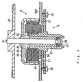
- Fig. 1 shows a first embodiment of a mounting structure for mounting a motor to a mounting base according to the present invention.
- the spindle motor 1 shown in Fig. 1 is an outer rotor type brushless motor (brushless DC motor) for rotating an optical disc such as a compact disc (CD), a CD-ROM, a CD-R or the like, for example.
- a feed chassis 220 shown in Fig. 1 is one example of a mounting base.
- the motor 1 shown in Fig, 1 is generally composed from a rotor 4, and a stator 2 equipped with a bearing portion for rotatably supporting the rotor 4.
- the stator 2 is constructed from a slide bearing 21, bearing fixing bolts 22 for mounting the slide bearing 21 to the feed chassis 220 in a fixed state, and a stator core 23 provided with coils 24, and the like.
- the slide bearing 21 rotatably supports a rotation shaft 41 of the rotor 4.
- the bearing fixing bolts 22 and the slide bearing 21 constitute a bearing portion which rotatably supports the rotation shaft 41.
- an insertion hole 211 through which the rotation shaft 41 is inserted, and two insertion holes 212 through which the bearing fixing bolts 22 are respectively inserted are formed in the slide bearing 21.
- the slide bearing 21 is mounted in a fixed state to the feed chassis 220 by inserting the bearing fixing bolts 22 through the insertion holes 212, respectively, and then fastening the bearing fixing bolts 22 to the feed chassis 220 by nuts, for example.
- the stator core 23 has an annular portion 25 in the center portion thereof, and by fitting the bearing fixing bolts 22 into holes formed in the annular portion 25, the stator core 23 is fixed with respect to the feed chassis 220 through the bearing fixing bolts 22 and the slid bearing 21.
- Nine magnetic poles 26 are formed on the annular portion 25 radially at equal angular spacings in the circumferential direction. Wires are wound around these magnetic poles 26 to form the coils 24.
- the rotor 4 is roughly constructed from the rotation shaft 41, a shaft coupling portion 45 into which one end (the top end in the example shown in Fig. 1) of the rotation shaft 41 is inserted and fixed thereto, a roughly cup-shaped yoke 43 fixedly mounted on the shaft coupling portion 45, permanent magnets 44 provided on the inner circumferential surface of the yoke 43, and a disc-shaped turntable 42 provided on the yoke 43, and the like.
- a convex portion 451 for positioning an optical disc placed on the turntable 42 is formed on the shaft attaching portion 45.
- An optical disc is placed on the turntable 42 in a state that the convex portion 451 is inserted through a hole (the center hole 102 shown in Fig. 3 described later) formed in the center of the optical disc.
- the turntable 42 is provided on the top of the yoke 43, when the yoke 43 is rotated, the turntable 42 is also rotated at the same time.
- the turntable 42 can hold the optical disc in cooperation with a clamp member (not shown in the drawing) by the attractive force of a magnet or the like, for example, and at the time of ejection, the turntable 42 is lowered so as to be able to release the optical disc. Further, an antislip pad 421 is provided on an upper peripheral portion of the turntable 42 to prevent the optical disc from slipping.
- the bottom end of the rotation shaft 41 is formed into a convex rounded shaft tip portion 411. Further, a shaft groove 412 is formed adjacent to the shaft tip portion 411. The shaft groove 412 is formed by cutting away a peripheral portion of the rotation shaft 41 to form an annular groove.
- the feed chassis 220 is used as a mounting base of the present invention.
- the feed chassis 220 is formed from a metal plate material.
- a shaft end receiving portion 221 is formed in the feed chassis 220 at a position where the motor 1 is to be mounted.
- the shaft end receiving portion 221 is formed by carrying out a drawing process to a part of the feed chassis in a die so that the part of the feed chassis undergoes plastic deformation to form a concave depression in the feed chassis 220, whereby the shaft end receiving portion 221 is integrally formed on the feed chassis 220.
- the reference number 210 is a printed circuit board having a circuit for supplying a driving electric current and control signals to the motor 1.
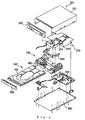
- Fig. 3 is a perspective view which shows the overall structure of a disc drive equipped with the feed chassis 220 on which the motor 1 shown in Fig. 1 is mounted.
- Fig. 4 is an exploded perspective view of the disc drive shown in Fig. 3.
- the disc drive 50 is an apparatus for carrying out recording and/or playback of a disc 100 such as a CD-ROM, a music CD, a DVD or the like.
- the disc drive is generally composed from a loading chassis 120, a disc tray 160 for conveying a disc, a main circuit board 200 arranged in the rear bottom portion of the loading chassis 120, the feed chassis 220, a pivotal frame 340, a loading cam mechanism 460 which operates the pivotal frame 340 and the disc tray 160 provided on the loading chassis 120, and a casing 360 which houses all these components.
- the casing 360 is constructed from a bottom cover 380 which covers the bottom of the disc apparatus 50, an outer cover 362 which covers the top, the left and right sides and the back of the disc drive 50, and a front panel 390 which covers the front of the disc drive 50.
- the disc tray 160 has a disc supporting portion 162 in which a disc 100 is to be placed.
- the disc tray 160 is movable in the forward and backward directions with respect to the loading chassis 120 between a disc ejection position and a disc playback position to convey the disc 100.
- the motor 1 is mounted on the feed chassis 220.
- the feed chassis 220 is equipped with an optical pick-up 250 for carrying out recording or playback of the disc 100, and an optical pick-up moving mechanism 274 provided with a sliding mechanism which moves the optical pick-up 250 in a radial direction of the disc 100.
- the pivotal frame 340 is a member for pivotally displacing the feed chassis 220 between a raised position (a position which makes it possible to carry out playback or recording of the disc 100) and a lowered position (a position for evacuating the feed chassis 220 when carrying out loading/ejecting operation of the disc 100).
- the disc drive 50 includes a loading mechanism for pivotally displacing the feed chassis 220 so that the feed chassis 220 is positioned at the raised position when the disc tray 160 is at the disc playback position, and the feed chassis 220 is positioned at the lowered position when the disc tray 160 is at the disc ejection position.
- a brace 81 is placed in the depressed portion (concave portion) which forms the shaft end receiving portion 221 of the feed chassis 220.
- the bearing fixing bolts 22, 22 are inserted into the holes formed in the annular portion 25 of the stator core 23, the insertion holes 212, 212 of the slide bearing 21, and then bolt holes formed in the feed chassis 220. Then, by fastening the bearing fixing bolts 22 with nuts (not shown in the drawings), the stator 2 is fixed with respect to the feed chassis 220.
- the rotation shaft 41 of the rotor 4 is inserted through the insertion hole 211 of the slide bearing 21 of the stator 2, and the shaft tip portion 411 of the rotation shaft 41 is inserted in the brace 81. Further, when the shaft tip portion 411 of the rotation shaft 41 is pushed in, the brace 81 undergoes elastic deformation in that direction, and when further pushing is carried out to completely insert the shaft tip portion 411, the brace 81 is restored by an elastic force to engage with the shaft groove 412. In this way, the motor 1 is mounted to the feed chassis 220.
- stator 2 because there is no need to provide the stator 2 with a separate part for supporting one end of the rotation shaft 41, the structure of the stator 2 is simplified, and this makes it possible to reduce the manufacturing cost of the motor 1.
- the shaft tip portion 411 of the shaft portion 41 is positioned in the depression (concave portion / that is, the shaft end receiving portion 221) integrally formed on the mounting base, and this makes it possible to mount the motor 1 to the mounting base with the simple operation of only mounting the stator and the rotor to the mounting base. Namely, the operation of mounting the motor 1 to the mounting base can be carried out easily.
- the mounting base is formed from a metal material, it has a certain weight, and for this reason, stability is increased. This makes it possible to reduce vibrations due to eccentric rotation of the disc rotated by the motor mounted on the mounting base.
- the shaft end receiving portion 221 is integrally formed on the mounting base, the processing steps for manufacturing the mounting base are reduced to a minimum, and this makes it possible to easily manufacture the mounting base. Further, it is possible to prevent the number of components from increasing.
- stator 2 is simplified and the number of components is reduced, it becomes possible to design a motor which is compact and light-weight.
- the shaft end receiving portion 221 is formed by a drawing process, but the shaft end receiving portion 221 may also be formed by other processing methods.
- the mounting base is constructed from a metal material, but it is also possible to construct the mounting base from another material such as wood or plastic or the like instead of metal.
- Fig. 5 is a perspective view which shows a second embodiment having such a structure.
- a shaft end receiving portion 221a may be manufactured from a separate metal plate member in which a depression is formed by a drawing process.
- a mounting base e.g., a feed chassis 220a
- a feed chassis 220a e.g., a feed chassis 220a
- the mounting structure for mounting the motor 1 to the mounting base was shown for the example application to a recording/playback apparatus or playback apparatus (that is, an optical disc drive) which uses an optical recording medium such as an optical disc or the like.
- a recording/playback apparatus or playback apparatus that is, an optical disc drive
- the example of the disc drive equipped with the mounting structure for mounting the motor 1 to the mounting base was shown as the type in which the disc is held in the horizontal direction, but it is also possible to apply the mounting structure of the present invention to a disc drive of the type that holds a disc in the vertical direction.
- the mounting structure for mounting a motor to a mounting base there is no need to provide the stator with a structure for supporting one end of the rotation shaft, and this makes it possible to reduce the number of components forming the motor.
- the processing steps for manufacturing the mounting base are reduced to a minimum, and this makes it possible to easily manufacture the mounting base equipped with the shaft end receiving portion.
- the mounting base is formed from a metal material, it is possible to reduce vibrations due to eccentric rotation of the disc rotated by the mounted motor.
- the shaft end receiving portion is formed by a drawing process, it is possible to easily form the shaft end receiving portion which supports one end of the rotation shaft.
- the mounting structure of the present invention is applied to a structure in which a feed chassis is used as a mounting base for a motor, it is possible to reduce the number of components forming the motor.
Landscapes
- Motor Or Generator Frames (AREA)
- Rotational Drive Of Disk (AREA)
Abstract
Description
Claims (5)
- In a mounting structure of a motor to a mounting base, the motor including a rotor having a rotation shaft for rotating a disc-shaped recording medium and a stator having a bearing portion for rotatably supporting the rotation shaft, wherein the mounting base is provided with a shaft end receiving portion for restricting the movement of the rotation shaft in at least one direction of the axial directions of the rotation shaft.
- The mounting structure as claimed in claim 1, wherein the shaft end receiving portion restricts the downward movement of the rotation shaft, and includes a concave part integrally formed with the mounting base.
- The mounting structure as claimed in claim 1, wherein the shaft end receiving portion is formed from a metallic material.
- The mounting structure as claimed in claim 3, wherein the shaft end receiving portion is formed by means of drawing.
- The mounting structure as claimed in any one of claims 1 to 4, wherein the mounting base is a feed chassis in an optical disc drive which includes an optical pick-up at least for reproducing an optical disc, and which is constructed so that a portion of the feed chassis on which the pick-up is provided is displaceable between a raised position and a lowered position, and the motor is a spindle motor provided on the chassis for rotating the optical disc.
Applications Claiming Priority (2)
| Application Number | Priority Date | Filing Date | Title |
|---|---|---|---|
| JP2002090903 | 2002-03-28 | ||
| JP2002090903A JP2003289642A (en) | 2002-03-28 | 2002-03-28 | Motor mounting structure to mounting base |
Publications (3)
| Publication Number | Publication Date |
|---|---|
| EP1349156A2 true EP1349156A2 (en) | 2003-10-01 |
| EP1349156A3 EP1349156A3 (en) | 2004-07-28 |
| EP1349156B1 EP1349156B1 (en) | 2007-05-02 |
Family
ID=27800506
Family Applications (1)
| Application Number | Title | Priority Date | Filing Date |
|---|---|---|---|
| EP03006838A Expired - Lifetime EP1349156B1 (en) | 2002-03-28 | 2003-03-27 | Structure for mounting a motor on a base |
Country Status (5)
| Country | Link |
|---|---|
| US (1) | US20030185141A1 (en) |
| EP (1) | EP1349156B1 (en) |
| JP (1) | JP2003289642A (en) |
| CN (1) | CN1298093C (en) |
| DE (1) | DE60313525T2 (en) |
Families Citing this family (9)
| Publication number | Priority date | Publication date | Assignee | Title |
|---|---|---|---|---|
| KR100494464B1 (en) * | 2002-03-05 | 2005-06-13 | 삼성전기주식회사 | Optical write and read apparatus |
| JP2005192313A (en) * | 2003-12-25 | 2005-07-14 | Hitachi Global Storage Technologies Netherlands Bv | Data storage device |
| JP2007174754A (en) * | 2005-12-20 | 2007-07-05 | Pioneer Electronic Corp | Spindle motor, manufacturing method thereof, and disk drive device |
| JP2009080873A (en) * | 2007-09-25 | 2009-04-16 | Hitachi Ltd | Optical information recording / reproducing device |
| JP2009211740A (en) * | 2008-02-29 | 2009-09-17 | Panasonic Corp | Method of manufacturing base member, method of manufacturing motor, method of manufacturing information apparatus, base member, motor, and information apparatus |
| KR101048248B1 (en) | 2009-07-28 | 2011-07-08 | 엘지이노텍 주식회사 | Spindle motor |
| KR20130022344A (en) * | 2011-08-26 | 2013-03-06 | 삼성전기주식회사 | Spindle motor |
| CN104810961B (en) * | 2014-01-28 | 2017-05-10 | 建准电机工业股份有限公司 | Motor with a stator having a stator core |
| JP6184934B2 (en) * | 2014-12-10 | 2017-08-23 | ミネベアミツミ株式会社 | motor |
Family Cites Families (7)
| Publication number | Priority date | Publication date | Assignee | Title |
|---|---|---|---|---|
| JPH0646036B2 (en) * | 1982-11-19 | 1994-06-15 | セイコー電子工業株式会社 | Axial flow molecular pump |
| JPH01321853A (en) * | 1988-06-22 | 1989-12-27 | Mitsubishi Electric Corp | brushless motor |
| JP2727409B2 (en) * | 1994-04-06 | 1998-03-11 | マブチモーター株式会社 | Small motor |
| JPH08249808A (en) * | 1995-03-08 | 1996-09-27 | Sanyo Electric Co Ltd | Turntable device for disk player |
| JP2863908B2 (en) * | 1995-10-26 | 1999-03-03 | ミネベア株式会社 | Hard disk drive device and method of manufacturing the same |
| JP3544800B2 (en) * | 1996-09-30 | 2004-07-21 | 松下電器産業株式会社 | Magnetic recording / reproducing device |
| JP2001314058A (en) * | 2000-04-28 | 2001-11-09 | Nippon Densan Corp | Spindle motor |
-
2002
- 2002-03-28 JP JP2002090903A patent/JP2003289642A/en active Pending
-
2003
- 2003-03-25 CN CNB031208932A patent/CN1298093C/en not_active Expired - Fee Related
- 2003-03-27 EP EP03006838A patent/EP1349156B1/en not_active Expired - Lifetime
- 2003-03-27 DE DE60313525T patent/DE60313525T2/en not_active Expired - Lifetime
- 2003-03-28 US US10/402,474 patent/US20030185141A1/en not_active Abandoned
Also Published As
| Publication number | Publication date |
|---|---|
| EP1349156A3 (en) | 2004-07-28 |
| JP2003289642A (en) | 2003-10-10 |
| CN1298093C (en) | 2007-01-31 |
| DE60313525T2 (en) | 2007-12-27 |
| CN1449089A (en) | 2003-10-15 |
| DE60313525D1 (en) | 2007-06-14 |
| EP1349156B1 (en) | 2007-05-02 |
| US20030185141A1 (en) | 2003-10-02 |
Similar Documents
| Publication | Publication Date | Title |
|---|---|---|
| CN102290905B (en) | Motor and method of manufacturing the same | |
| EP1349156B1 (en) | Structure for mounting a motor on a base | |
| JP2000011630A (en) | Disk drive | |
| US6570836B2 (en) | Disk clamping mechanism | |
| US5363260A (en) | Magnetic disk apparatus and method for manufacturing the same | |
| US5689388A (en) | Reduced-height magnetic disk drive unit, and disk mounting device for the unit | |
| US6469970B2 (en) | Disk-reproducing apparatus with integrally formed disk table and rotor | |
| JP2003059253A (en) | Spindle motor structure and thin flexible disk drive with it | |
| US6094324A (en) | Disk drive with chassis opening for receiving disk mounting portion of motor drive cone | |
| JP2000308318A (en) | Iron core coil motor and disk drive device | |
| US20040114497A1 (en) | Spindle motor for driving optical disk | |
| US6166878A (en) | Disk drive having the motor core secured via the disk rotating bearing flange to the chassis | |
| JPH11176054A (en) | Turntable device of disk player | |
| CN102034510A (en) | Motor and disk drive apparatus | |
| JPH08249808A (en) | Turntable device for disk player | |
| JP2003319604A (en) | Disk drive apparatus and system | |
| US6499210B2 (en) | Method of accurately and easily mounting a drive motor to a frame member in assembling a disk drive for driving a flexible disk | |
| JP4608808B2 (en) | Medium loading device and disk device | |
| EP1564745B1 (en) | Disk device having clamper on board | |
| JP2740463B2 (en) | Disk rotation drive | |
| JP2003068067A (en) | Disk device base plate and disk device using the same | |
| JPH10208371A (en) | Turntable driving device of disk player | |
| JPH10275389A (en) | Disk holder for disk player | |
| US20070271575A1 (en) | Disk Drive Unit | |
| JP2007080405A (en) | Disk rotating device |
Legal Events
| Date | Code | Title | Description |
|---|---|---|---|
| PUAI | Public reference made under article 153(3) epc to a published international application that has entered the european phase |
Free format text: ORIGINAL CODE: 0009012 |
|
| AK | Designated contracting states |
Kind code of ref document: A2 Designated state(s): AT BE BG CH CY CZ DE DK EE ES FI FR GB GR HU IE IT LI LU MC NL PT SE SI SK TR |
|
| AX | Request for extension of the european patent |
Extension state: AL LT LV MK RO |
|
| PUAL | Search report despatched |
Free format text: ORIGINAL CODE: 0009013 |
|
| AK | Designated contracting states |
Kind code of ref document: A3 Designated state(s): AT BE BG CH CY CZ DE DK EE ES FI FR GB GR HU IE IT LI LU MC NL PT SE SI SK TR |
|
| AX | Request for extension of the european patent |
Extension state: AL LT LV MK RO |
|
| 17P | Request for examination filed |
Effective date: 20040920 |
|
| AKX | Designation fees paid |
Designated state(s): DE |
|
| 17Q | First examination report despatched |
Effective date: 20041124 |
|
| GRAP | Despatch of communication of intention to grant a patent |
Free format text: ORIGINAL CODE: EPIDOSNIGR1 |
|
| GRAS | Grant fee paid |
Free format text: ORIGINAL CODE: EPIDOSNIGR3 |
|
| GRAA | (expected) grant |
Free format text: ORIGINAL CODE: 0009210 |
|
| AK | Designated contracting states |
Kind code of ref document: B1 Designated state(s): DE |
|
| REF | Corresponds to: |
Ref document number: 60313525 Country of ref document: DE Date of ref document: 20070614 Kind code of ref document: P |
|
| PLBE | No opposition filed within time limit |
Free format text: ORIGINAL CODE: 0009261 |
|
| STAA | Information on the status of an ep patent application or granted ep patent |
Free format text: STATUS: NO OPPOSITION FILED WITHIN TIME LIMIT |
|
| 26N | No opposition filed |
Effective date: 20080205 |
|
| PGFP | Annual fee paid to national office [announced via postgrant information from national office to epo] |
Ref country code: DE Payment date: 20120411 Year of fee payment: 10 |
|
| REG | Reference to a national code |
Ref country code: DE Ref legal event code: R119 Ref document number: 60313525 Country of ref document: DE Effective date: 20131001 |
|
| PG25 | Lapsed in a contracting state [announced via postgrant information from national office to epo] |
Ref country code: DE Free format text: LAPSE BECAUSE OF NON-PAYMENT OF DUE FEES Effective date: 20131001 |