EP1349054A2 - Method and system for interpreting imprecise object selection paths - Google Patents
Method and system for interpreting imprecise object selection paths Download PDFInfo
- Publication number
- EP1349054A2 EP1349054A2 EP03251706A EP03251706A EP1349054A2 EP 1349054 A2 EP1349054 A2 EP 1349054A2 EP 03251706 A EP03251706 A EP 03251706A EP 03251706 A EP03251706 A EP 03251706A EP 1349054 A2 EP1349054 A2 EP 1349054A2
- Authority
- EP
- European Patent Office
- Prior art keywords
- image
- object selection
- image objects
- user
- image object
- Prior art date
- Legal status (The legal status is an assumption and is not a legal conclusion. Google has not performed a legal analysis and makes no representation as to the accuracy of the status listed.)
- Withdrawn
Links
Images



Classifications
-
- G—PHYSICS
- G06—COMPUTING OR CALCULATING; COUNTING
- G06F—ELECTRIC DIGITAL DATA PROCESSING
- G06F3/00—Input arrangements for transferring data to be processed into a form capable of being handled by the computer; Output arrangements for transferring data from processing unit to output unit, e.g. interface arrangements
- G06F3/01—Input arrangements or combined input and output arrangements for interaction between user and computer
- G06F3/048—Interaction techniques based on graphical user interfaces [GUI]
- G06F3/0481—Interaction techniques based on graphical user interfaces [GUI] based on specific properties of the displayed interaction object or a metaphor-based environment, e.g. interaction with desktop elements like windows or icons, or assisted by a cursor's changing behaviour or appearance
Definitions
- the present invention finds particular advantage in editing text and line art contained in an image.
- Documents which are faxed or which are copied on a digital copier typically involve images that contain primarily text and graphics.
- OCR Optical Character Recognition
- the present invention minimizes the need for extraneous processing and provides added flexibility to defining both text and graphical image information so as to allow the editing of a wider range of textual and graphical data in an image.
- T p (v/r'), where P is a constant taking the value 10,000, v is velocity in pixels per second, and r' is given by min(r, max_R), where r is the radius of curvature at that location along the path, and max_R is a constant taking the value 800.
- T Tolerance Factor
- the objects "G”, "r”, “e”, “e” and “n” lie entirely inside the outer boundary 224 of the tolerance tunnel and are selected.
- the object “P” lies entirely outside the inner boundary 226 of the tolerance tunnel, and is rejected.
- the object “O” extends beyond both boundaries of the tolerance tunnel and is split according to the selection path at 232.
- the resulting set of selected objects is shown at 234 and the resulting set of not selected objects is shown at 236.
- step 340 objects assigned to category VI are split according to the selection gesture path. The portions of these objects falling inside the selection gesture path are selected. This is illustrated in Figure 4, where object "O" has been split and partial object 450 has been selected and partial object 452 was not selected.
- each remaining group is evaluated in turn, and all of the image objects in the group are selected or rejected based, for example, on a weighted vote for that group.
- the weighting of each vote is the pixel area of the image object.
- Each image object votes as follows, according to its tunnel proximity category: Category Vote I 2 II -2 III 0 IV 1 V -1
- Figure 5 illustrates another embodiment of the method for interpreting imprecise selection gestures in situations in which the image material to be selected exists as undifferentiated image objects, such as connected components, characters, words, lines of text, or individual figures.
- This method finds beneficial application when the image is represented as a single raster bitmap containing foreground image objects on a field of background pixel values.
- the flowchart shows the steps for interpreting imprecise gestures in this situation.
- Input image data is received at step 510.
- boundaries between perceptual image objects are computed at step 520 using various techniques of computational geometry, for example the Distance Transform and the Voronoi diagram, both of which are well known in the art.
- FIG 6 another aspect of this invention permits the user's selection rectangles to be used not as literal definitions of regions within which image material should be selected, but as approximate specifiers of image material to be selected.
- Figure 6 shows an example in which the user's selection rectangle 610 intersects characters, but in which the user's intent was likely to be to select only and entirely the characters "on projects".
- the embodiments of the present invention described hereinabove may be used with rectangle drag selection gestures as well as with polygonal selection paths and drawn freeform paths. In place of estimates of carefulness along sections of the selection gesture, the entire boundary of the selection rectangle is assigned a value of carefulness based on the speed at which the rectangle is dragged, or else by a specific action by the user.
Landscapes
- Engineering & Computer Science (AREA)
- General Engineering & Computer Science (AREA)
- Theoretical Computer Science (AREA)
- Human Computer Interaction (AREA)
- Physics & Mathematics (AREA)
- General Physics & Mathematics (AREA)
- User Interface Of Digital Computer (AREA)
- Processing Or Creating Images (AREA)
Abstract
Description
- This invention relates generally to user interfaces to computational devices, and more particularly to applications in which displayed objects are selected and arranged in document images.
- Two types of interactive drawing/sketching/editing applications are currently in use, both of which support creation of new image material, through draw operations, and selection and manipulation of existing material, through editing operations. The types of interactive applications are distinguished by the emphasis placed on "sketch" and "editing" operations. In an image "editing" program, selection and manipulation of image objects is the primary activity. Therefore, stylus or mouse interaction is designed primarily to interpret stylus input as selection gestures, and the default interpretation of mouse or stylus activity is selection of existing image objects for manipulation. Tools for drawing objects are provided by auxiliary command objects, usually menus.
- In a "sketch" program, however, the primary activity is the "draw" operation. To facilitate the sketching process, it is important for users to be able to quickly execute a series of markings such as handwritten or sketched strokes, without having to perform a menu initiation command at every stroke. These programs are designed such that draw operations can be the default interpretation of mouse or stylus activity. The disadvantage to this type of program is that when priority is placed on draw operations, selection operations become demoted and require explicit menu choices or button clicks to invoke a selection, which impedes the smooth flow of multiple selection and manipulation operations.
- In both types of interactive applications, it can be very difficult to select and move, delete, or otherwise modify salient collections of markings at will. In particular, users are sometimes imprecise in the ways that they draw encircling gestures to select image objects for further manipulation. They may unintentionally clip off a piece of an image object they intend to select. At other times, they may actually intend to split off the very same piece of this image object. One of the major drawbacks to existing graphical editors is their inability to interpret selection gestures in light of precomputed perceptual objects, so that imprecise gestures may be interpreted to either deliver the literal objects defined by the gesture, or the perceptually significant objects identified in the precomputation stage.
- U.S. Patent No. 5,485,565 to Saund et al. titled "Gestural Indicators for Selecting Graphic Objects" discloses a graphical imaging system, in which the rough location, size and shape of objects in the image is summarized by a first characteristic descriptor, representing a parametric "pose" computed for each object. A second characteristic descriptor, for example a "gesture matching" function, is provided in order to select the single object, or the set of objects, that best comports with the user's selection gesture. When most closely matched, these key characteristic descriptors permit simple and natural user gestures to distinguish among a large set of graphic objects that may overlap both spatially. User gestures can be simple slashes passing through the object, or quick, coarse approximations of objects' shapes.
- U.S. Patent No. 5,513,309 to Meier et al. titled "Graphic Editor User Interface for a Pointer-Based Computer System" discloses a graphical editor arranged to permit the user to edit selected graphic objects by highlighting the objects and moving them with editing handles. A bounding box is also drawn about the selected portions of the object. In various aspects of the invention, the user is permitted to edit the object by executing specific actions, including resizing, duplicating, distorting and moving either the entire object or only selected portions. After any of the editing operations is performed, the display is updated to reflect changes made during the editing step.
- The present invention offers a new tool for computer assisted drawing, one that provides users with the ability to make imprecise selection gestures while the application applies certain rules and image analysis operations to infer the user's intent.
- Briefly stated, and in accordance with one aspect of the present invention, there is disclosed herein a graphical input and display system having a user interface for selecting and creating image object elements and includes input devices permitting a user to manipulate elements of electronic images. A processor, connected to the system, receives requests for various image object selection operations and also accesses a memory structure. The system memory structure includes a user interaction module, which allows a user to select image objects, an image object selection module for interpreting imprecise image object selection paths, and data memory.
- In another aspect of the invention, there is disclosed a method for utilizing a user interface on a graphical input and display system for interpreting imprecise image object selection paths. After image material is selected, the system evaluates the characteristics of the selection path and also evaluates the proximity of the image material to the selection gesture. The image objects affected by the image object selection gesture are manipulated to identify those image objects to be selected.
- In yet another aspect of the invention, there is provided an article of manufacture in the form of a computer usable medium having computer readable program code embodied in the medium. When the program code is executed by the computer, the computer usable medium causes the computer to perform method steps for interpreting imprecise image object selection gestures. The program readable code causes the computer to evaluate carefulness along an image object selection path which has been input by a user. The program code then causes the computer to form a tolerance tunnel, which includes an inner tunnel boundary and an outer tunnel boundary. The image objects affected by the selection gesture are then manipulated to determine which image objects are selected.
- Some examples of systems and methods according to the present invention will now be described with reference to the accompanying drawings, in which:-
- FIG. 1 is a block diagram showing general components of a system that can interpret imprecise selection paths according to the invention;
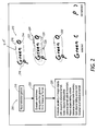
- FIG. 2 is a flow chart showing steps in interpreting an imprecise selection path according to one embodiment of the present invention;
- FIG. 3 is a flow chart showing steps in interpreting an imprecise selection path according to another embodiment of the present invention;
- FIG. 4 illustrates the processing steps according to the embodiment of the present invention of Figure 3;
- FIG. 5 is a flow chart showing steps in interpreting an imprecise selection path according to yet another embodiment of the present invention; and
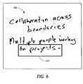
- FIG. 6 illustrates interpretation of selection rectangles according to the invention.
-
- Disclosed herein is a method for interpreting imprecise selection paths in a system for selecting and arranging visible material in document images. In the following description numerous specific details are set forth in order to provide a thorough understanding of the present invention. It would be apparent, however, to one skilled in the art to practice the invention without such specific details. In other instances, specific implementation details such as parsing techniques for extracting characters from a document image, have not been shown in detail in order not to unnecessarily obscure the present invention.
- As will become apparent in the description below, the present invention finds particular advantage in editing text and line art contained in an image. Documents which are faxed or which are copied on a digital copier typically involve images that contain primarily text and graphics. As described with respect to the prior art, it is common that in order to edit any of the text contained in the image, extraneous processing such as Optical Character Recognition (OCR) or the placement of image information into layers must be performed. As will become apparent, the present invention minimizes the need for extraneous processing and provides added flexibility to defining both text and graphical image information so as to allow the editing of a wider range of textual and graphical data in an image.
- Referring now to Figure 1,
system 100 includesprocessor 110, connected to receive signals fromimage input device 120 anduser input device 130.Image input device 120 could be a scanner, a facsimile receiver or other image receiver, a camera, or other appropriate device or could be a part of local or remote memory that stores an image in digital form.User input device 130 could, for example, be a keyboard with a mouse.Processor 110 can also be connected toimage output device 140, such as a screen display, a printer, a facsimile transmitter or other image transmitter, or a part of local or remote memory that can store an image in digital form. -
Processor 110 is also connected to accessprogram memory 150 anddata memory 160.Program memory 150 includesuser interaction module 152, image object boundary detection module154path matching module 156, and may also include an optionalobject splitting module 158.Data memory 160 includes imageinput data structure 162, primary imageobjects data structure 164, objectgroup data structure 166, selectionpath data structure 168, tolerancetunnel data structure 170, objectboundary data structure 172, and selectedobjects data structure 174. - Figure 2 illustrates one embodiment of the method for interpreting imprecise selection gestures in situations in which image objects are presented as independent image objects in a display. In Figure 2
flowchart 200 shows the steps for interpreting imprecise gestures in this situation and the illustrations beside the flowchart show examples of the processing steps. Initially, a display contains the characters "G", "r", "e", "e", "n", "O" and "P" at example 212. Atstep 210, a user inputs a selection gesture, shown aspath 216 in example 212. In this example, the gesture begins atpoint 215 and ends at the arrow. On the left side ofpath 216, approaching and leavingpoint 218, the path has high velocity, and the path has low velocity on the right side ofpath 216, approaching and leavingpoint 214. The user interaction module collects the path of the user's gesture and passes it tostep 220 for evaluation as to carefulness along the selection gesture path. At each location along the selection gesture, the user's application of gesture drawing carefulness is evaluated. Various approaches may be used to evaluate carefulness, as will be appreciated by those skilled in the art. One example approach is application of the expressionselection path 222 is bounded by a tolerance tunnel defined bytolerance tunnel paths selection path 222, where the gesture velocity was low; it approaches a maximum as it passes along the left side ofselection path 222, where the gesture velocity was high. The tolerance factor is shown astolerance tunnel width 228. - At
step 230 each foreground image object is considered with respect to the tolerance tunnel. If an image object is found to lie entirely inside the outer boundary of the tolerance tunnel, then that object is selected. If an image object is found to lie entirely outside the inner boundary of the tolerance tunnel, then that object is rejected. If the dimensions of the image object extend beyond both boundaries of the tolerance tunnel, then the image object is split according to the selection path, and only the portion inside the path is selected. Optionally, this method may be implemented in such a way that image objects are not split, but are either selected or rejected from selection based on the area of the object falling inside the outer tolerance tunnel boundary versus outside the inner tolerance tunnel boundary, or other similar criteria. In the example, the objects "G", "r", "e", "e" and "n" lie entirely inside theouter boundary 224 of the tolerance tunnel and are selected. The object "P" lies entirely outside theinner boundary 226 of the tolerance tunnel, and is rejected. The object "O" extends beyond both boundaries of the tolerance tunnel and is split according to the selection path at 232. The resulting set of selected objects is shown at 234 and the resulting set of not selected objects is shown at 236. - Figures 3 and 4 illustrate another embodiment of the method for interpreting imprecise selection gestures in situations in which image objects may belong to groups. In Figure 3 flowchart 300 shows the steps for interpreting imprecise gestures in this situation and Figure 4 illustrates an example of the processing steps. Initially, a display may contain
characters 410 forming the words "Green", "O", "Red" and "Purple", in the arrangement shown at 400 in Figure 4. The system data memory contains data structures indicating that the characters form four groups, as illustrated. Numerous types of data structures may perform this function, including lists, arrays, and sets of pointers. Atstep 310 in Figure 3, the user interaction module collects the path of the user's gesture and passes that information to step 320, in which carefulness along the selection gesture is evaluated. In the example shown in Figure 4, the gesture begins atpoint 412 and ends atarrow 414.Path 420 has high velocity on the left side and bottom of the path, but low velocity on the right side ofpath 420, where it crosses the "O", as shown atlocation 425. - Referring now to Figure 3, at
step 320, at each location along the selection gesture, the user's degree of gesture drawing carefulness is evaluated. A tolerance factor is computed at each location along the selection gesture, and a tolerance tunnel is formed, as described hereinabove. This step is illustrated in Figure 4, wheregesture 420 is the user's selection path which is bounded by innertolerance tunnel boundary 424 and outertolerance tunnel boundary 422. - At
step 330 in Figure 3, each image object is evaluated with respect to the selection gesture path and the tolerance tunnel representing selection gesture carefulness. Each image object is assigned a categorical value depending on its proximity to the two tolerance tunnel boundaries. One possible set of categorical values may include - I: inside the inner tolerance tunnel boundary;
- II: outside the outer tolerance tunnel boundary;
- III: between the inner and outer tolerance tunnel boundaries;
- IV: spans the inner tolerance tunnel boundary;
- V: spans the outer tolerance tunnel boundary; or
- VI: spans both tolerance tunnel boundaries.
-
- This step is illustrated in Figure 4 at chart 430. As shown in the chart, "reen" fall inside the
inner tolerance boundary 424 and are in category I. "R" falls outside outertolerance tunnel boundary 422 and resides in category II. Objects "d" and "urpe" lie between inner and outertolerance tunnel boundaries tolerance tunnel boundary 424 and reside in category IV. Object "e" spans outertolerance tunnel boundary 422, placing it in category V, while object "O" spans both tolerance tunnel boundaries, placing it in category VI. - Referring again to Figure 3, at
step 340 objects assigned to category VI are split according to the selection gesture path. The portions of these objects falling inside the selection gesture path are selected. This is illustrated in Figure 4, where object "O" has been split andpartial object 450 has been selected andpartial object 452 was not selected. - At
step 350 in Figure 3, each remaining group is evaluated in turn, and all of the image objects in the group are selected or rejected based, for example, on a weighted vote for that group. The weighting of each vote is the pixel area of the image object. Each image object votes as follows, according to its tunnel proximity category:Category Vote I 2 II -2 III 0 IV 1 V -1 - At
step 360 group selection/rejection votes are used to assign selection/rejection decisions to individual objects. For each group, if the weighted vote is greater than 0, then all of the image objects comprising that group are selected. If the weighted vote is less than 0, then none of these objects are selected. If some image object belongs to more than one group and these groups are not either all selected or all rejected, then a second weighted vote is taken of all the groups to which the image object belongs. The weighting is the pixel area of all image objects forming the group. Groups that are selected vote the value 1, groups that are not selected vote the value -1. If the result is greater than 0, then the object in question is selected; if the result is less than 0, then the object in question is not selected. This is illustrated in Figure 4, which shows the groups "Purple" and "Green" 460 as selected and the group "Red" 470 as not selected. The group "Green O" 480 is not evaluated. - Figure 5 illustrates another embodiment of the method for interpreting imprecise selection gestures in situations in which the image material to be selected exists as undifferentiated image objects, such as connected components, characters, words, lines of text, or individual figures. This method finds beneficial application when the image is represented as a single raster bitmap containing foreground image objects on a field of background pixel values. In Figure 5 the flowchart shows the steps for interpreting imprecise gestures in this situation. Input image data is received at
step 510. In this embodiment, prior to or subsequent to the user performing a selection operation, boundaries between perceptual image objects are computed atstep 520 using various techniques of computational geometry, for example the Distance Transform and the Voronoi diagram, both of which are well known in the art. Local maxima (ridges) of the distance transform, or ridges provided by the Voronoi diagram, or an equivalent, are then passed through a filter atstep 530 to retain only significant ridges. Persons skilled in the art are aware of techniques for discarding insignificant ridge points whose direction vectors to generating points fall at an acute angle. - When the user's selection gesture is input at
step 550, points along the gesture are evaluated for degree of carefulness atstep 560. For complete selection gestures or portions of selection gestures whose carefulness value falls below a threshold, an attempt is made to find a path through significant Voronoi ridges that approximates the selection path, atstep 540. This may be accomplished through use of a variant on the A* search technique called path-matching, described in US-A-5,485,565. This path is used finally to define the selection region used to select foreground objects for subsequent processing atstep 570. - Referring now to Figure 6, another aspect of this invention permits the user's selection rectangles to be used not as literal definitions of regions within which image material should be selected, but as approximate specifiers of image material to be selected. Figure 6 shows an example in which the user's
selection rectangle 610 intersects characters, but in which the user's intent was likely to be to select only and entirely the characters "on projects". The embodiments of the present invention described hereinabove may be used with rectangle drag selection gestures as well as with polygonal selection paths and drawn freeform paths. In place of estimates of carefulness along sections of the selection gesture, the entire boundary of the selection rectangle is assigned a value of carefulness based on the speed at which the rectangle is dragged, or else by a specific action by the user. For example, under one possible user interface design, if in the course of performing the rectangle drag the user moves the dragged corner of the rectangle back and forth several times, then the rectangle is assigned a low carefulness value (for example, .2) and this is used in the course of processing as described hereinabove to select or exclude image material that might fall beyond or within the rectangle's precise bounds, respectively. - Although discussed with reference to text and line art, the operations illustrated herein apply equally well to any type of image object.
Claims (11)
- A method for utilizing a user interface on a graphical input and display system having user input means (130), image input means (120), a processor (110), a user interaction module for selecting image objects, an image object selection module for interpreting imprecise image object selection paths, and data memory means, comprising:receiving (210) a user input image object selection gesture;evaluating (220) the characteristics of said object selection gesture; andevaluating (230) the proximity of the image material to the selection gesture;
- The method for utilizing a user interface on a graphical input and display system according to claim 1, wherein the first evaluating step comprises evaluating (220) carefulness along said selection gesture by evaluating the proximity of image objects with respect to a bounded region defined by the gesture.
- A method according to claim 1 or claim 2, further comprising defining inner and outer boundaries of a bounded region, defined by the gesture in accordance with a carefulness evaluation.
- The method for utilizing a user interface on a graphical input and display system according to claim 3, further comprising manipulating the image objects affected by said image object selection gesture by:selecting those image objects falling within the outer boundary of said bounded region;rejecting those image objects falling outside the inner boundary of said bounded region; andsplitting those image objects falling across both of said inner boundary and said outer boundary of said bounded region.
- The method for utilizing a user interface on a graphical input and display system according to any of claims 2 to 4, further comprising assigning proximity category values.
- The method for utilizing a user interface on a graphical input and display system according to claim 5, when dependent on claim 3 or claim 4, wherein assigning said proximity category values comprises:identifying those image objects falling within said inner boundary of said bounded region;identifying those image objects falling outside said outer boundary of said bounded region;identifying those image objects falling between said inner boundary and said outer boundary of said bounded region;identifying those image objects spanning said inner boundary of said bounded region;identifying those image objects spanning said outer boundary of said bounded region; andidentifying those image objects spanning both said inner boundary and said outer boundary of said bounded region.
- The method for utilizing a user interface on a graphical input and display system according to claim 1, further comprising:computing (520) boundaries between perceptual image objects;filtering (530) said boundaries to retain significant boundaries; andperforming (540) a path-matching search to identify a modified image object selection path.
- A method according to claim 7, wherein computing (520) boundaries between said perceptual image objects comprises computing Voronoi ridges of foreground pixels; wherein filtering (530) said boundaries comprises filtering Voronoi ridges to retain geometrically significant ridges; and wherein performing (540) a path-matching search comprises identifying a preferred path through significant Voronoi ridge segments to approximate the user's image object selection path.
- A computer program product comprising a computer usable medium having computer readable program code embodied in said medium which, when said program code is executed by said computer causes said computer to per form method steps for interpreting imprecise image object selection paths, said method steps comprising:receiving a user input image object selection gesture;evaluating carefulness along said selection gesture;forming a bounded region having an inner boundary and an outer with respect to said selection gesture; andmanipulating the image objects falling within or traversed by said image object selection gesture.
- A graphical input and display system having a user interface for selecting and arranging image object elements in a source electronic image, comprising:user input means (130) for selecting and creating image objects;image input means (120) for entering the electronic image onto a display means;a processor (110), connected for receiving requests for image object selection operations and for accessing a memory structure;program memory means (150) comprising:user interaction module (152) for selecting image objects;image object selection module (154) for interpreting imprecise image object selection paths; anddata memory means (160).
- The graphical input and display system according to claim 10, wherein said program memory further comprises one or both of a path matching module and an object splitting module.
Applications Claiming Priority (2)
| Application Number | Priority Date | Filing Date | Title |
|---|---|---|---|
| US104523 | 2002-03-22 | ||
| US10/104,523 US7093202B2 (en) | 2002-03-22 | 2002-03-22 | Method and system for interpreting imprecise object selection paths |
Publications (2)
| Publication Number | Publication Date |
|---|---|
| EP1349054A2 true EP1349054A2 (en) | 2003-10-01 |
| EP1349054A3 EP1349054A3 (en) | 2005-07-20 |
Family
ID=27804322
Family Applications (1)
| Application Number | Title | Priority Date | Filing Date |
|---|---|---|---|
| EP03251706A Withdrawn EP1349054A3 (en) | 2002-03-22 | 2003-03-19 | Method and system for interpreting imprecise object selection paths |
Country Status (3)
| Country | Link |
|---|---|
| US (1) | US7093202B2 (en) |
| EP (1) | EP1349054A3 (en) |
| JP (1) | JP4294348B2 (en) |
Cited By (2)
| Publication number | Priority date | Publication date | Assignee | Title |
|---|---|---|---|---|
| WO2008111273A1 (en) | 2007-03-12 | 2008-09-18 | Konami Digital Entertainment Co., Ltd. | Information processing device, control method for information processing device, and information storage medium |
| CN110704153A (en) * | 2019-10-10 | 2020-01-17 | 深圳前海微众银行股份有限公司 | Interface logic analysis method, device, device and readable storage medium |
Families Citing this family (24)
| Publication number | Priority date | Publication date | Assignee | Title |
|---|---|---|---|---|
| US7137077B2 (en) * | 2002-07-30 | 2006-11-14 | Microsoft Corporation | Freeform encounter selection tool |
| US7631276B2 (en) * | 2003-12-29 | 2009-12-08 | International Business Machines Corporation | Method for indication and navigating related items |
| US7895537B2 (en) * | 2003-12-29 | 2011-02-22 | International Business Machines Corporation | Method and apparatus for setting attributes and initiating actions through gestures |
| US7496385B2 (en) | 2003-12-29 | 2009-02-24 | International Business Machines Corporation | Method for viewing information underlying lists and other contexts |
| US20070152961A1 (en) * | 2005-12-30 | 2007-07-05 | Dunton Randy R | User interface for a media device |
| US8146018B2 (en) * | 2006-04-28 | 2012-03-27 | Nintendo Co., Ltd. | Gesture-based control of multiple game characters and other animated objects |
| US8882590B2 (en) | 2006-04-28 | 2014-11-11 | Nintendo Co., Ltd. | Touch-controlled game character motion providing dynamically-positioned virtual control pad |
| US9024864B2 (en) | 2007-06-12 | 2015-05-05 | Intel Corporation | User interface with software lensing for very long lists of content |
| US20090100383A1 (en) * | 2007-10-16 | 2009-04-16 | Microsoft Corporation | Predictive gesturing in graphical user interface |
| JP4958979B2 (en) * | 2007-12-27 | 2012-06-20 | パイオニア株式会社 | Recording medium reproducing apparatus, recording medium reproducing method, recording medium reproducing program, and recording medium storing recording medium reproducing program |
| US8423916B2 (en) * | 2008-11-20 | 2013-04-16 | Canon Kabushiki Kaisha | Information processing apparatus, processing method thereof, and computer-readable storage medium |
| US20100281435A1 (en) * | 2009-04-30 | 2010-11-04 | At&T Intellectual Property I, L.P. | System and method for multimodal interaction using robust gesture processing |
| JP5804618B2 (en) * | 2009-05-28 | 2015-11-04 | 任天堂株式会社 | GAME PROGRAM, GAME DEVICE, GAME SYSTEM, AND GAME PROCESSING METHOD |
| JP5999829B2 (en) * | 2009-05-28 | 2016-09-28 | 任天堂株式会社 | GAME PROGRAM AND GAME DEVICE |
| US8635555B2 (en) * | 2010-06-08 | 2014-01-21 | Adobe Systems Incorporated | Jump, checkmark, and strikethrough gestures |
| WO2012147799A1 (en) * | 2011-04-26 | 2012-11-01 | 京セラ株式会社 | Electronic device |
| US8954890B2 (en) * | 2012-04-12 | 2015-02-10 | Supercell Oy | System, method and graphical user interface for controlling a game |
| GB2511668A (en) | 2012-04-12 | 2014-09-10 | Supercell Oy | System and method for controlling technical processes |
| US8814674B2 (en) | 2012-05-24 | 2014-08-26 | Supercell Oy | Graphical user interface for a gaming system |
| US9007390B2 (en) * | 2012-05-15 | 2015-04-14 | Evernote Corporation | Creation and manipulation of hand drawn objects with automatic grouping |
| JP5567097B2 (en) * | 2012-10-26 | 2014-08-06 | 株式会社東芝 | Electronic device, handwritten document display method, and display program |
| KR102203885B1 (en) * | 2013-04-26 | 2021-01-15 | 삼성전자주식회사 | User terminal device and control method thereof |
| EP3324270A1 (en) * | 2016-11-16 | 2018-05-23 | Thomson Licensing | Selection of an object in an augmented reality environment |
| US12321189B2 (en) * | 2019-05-06 | 2025-06-03 | Apple Inc. | Conversion of handwriting to text in text fields |
Citations (1)
| Publication number | Priority date | Publication date | Assignee | Title |
|---|---|---|---|---|
| US5523775A (en) | 1992-05-26 | 1996-06-04 | Apple Computer, Inc. | Method for selecting objects on a computer display |
Family Cites Families (18)
| Publication number | Priority date | Publication date | Assignee | Title |
|---|---|---|---|---|
| US5347295A (en) * | 1990-10-31 | 1994-09-13 | Go Corporation | Control of a computer through a position-sensed stylus |
| US6097392A (en) * | 1992-09-10 | 2000-08-01 | Microsoft Corporation | Method and system of altering an attribute of a graphic object in a pen environment |
| US5481278A (en) * | 1992-10-21 | 1996-01-02 | Sharp Kabushiki Kaisha | Information processing apparatus |
| US5513309A (en) | 1993-01-05 | 1996-04-30 | Apple Computer, Inc. | Graphic editor user interface for a pointer-based computer system |
| JPH08510851A (en) | 1993-03-25 | 1996-11-12 | ライブ ピクチャー,インコーポレイテッド | Image processing method and apparatus |
| US6535897B1 (en) * | 1993-05-20 | 2003-03-18 | Microsoft Corporation | System and methods for spacing, storing and recognizing electronic representations of handwriting printing and drawings |
| US5485565A (en) | 1993-08-04 | 1996-01-16 | Xerox Corporation | Gestural indicators for selecting graphic objects |
| JPH07160827A (en) * | 1993-12-09 | 1995-06-23 | Matsushita Electric Ind Co Ltd | Handwriting stroke editing apparatus and method |
| JPH07281810A (en) * | 1994-04-02 | 1995-10-27 | Wacom Co Ltd | Computer system with multi-device input system |
| US5760773A (en) | 1995-01-06 | 1998-06-02 | Microsoft Corporation | Methods and apparatus for interacting with data objects using action handles |
| US6730862B1 (en) | 1995-12-27 | 2004-05-04 | Lsi Logic Corporation | Erase feature in pen-based computing |
| US5861886A (en) | 1996-06-26 | 1999-01-19 | Xerox Corporation | Method and apparatus for grouping graphic objects on a computer based system having a graphical user interface |
| JP4089051B2 (en) * | 1998-02-18 | 2008-05-21 | セイコーエプソン株式会社 | Image processing apparatus and image processing method |
| WO1999056198A2 (en) * | 1998-04-24 | 1999-11-04 | Natural Input Solutions Inc. | Pen based edit correction interface method and apparatus |
| US6459442B1 (en) * | 1999-09-10 | 2002-10-01 | Xerox Corporation | System for applying application behaviors to freeform data |
| US6664991B1 (en) * | 2000-01-06 | 2003-12-16 | Microsoft Corporation | Method and apparatus for providing context menus on a pen-based device |
| US7142205B2 (en) * | 2000-03-29 | 2006-11-28 | Autodesk, Inc. | Single gesture map navigation graphical user interface for a personal digital assistant |
| US20020015064A1 (en) * | 2000-08-07 | 2002-02-07 | Robotham John S. | Gesture-based user interface to multi-level and multi-modal sets of bit-maps |
-
2002
- 2002-03-22 US US10/104,523 patent/US7093202B2/en not_active Expired - Fee Related
-
2003
- 2003-03-19 JP JP2003074671A patent/JP4294348B2/en not_active Expired - Fee Related
- 2003-03-19 EP EP03251706A patent/EP1349054A3/en not_active Withdrawn
Patent Citations (1)
| Publication number | Priority date | Publication date | Assignee | Title |
|---|---|---|---|---|
| US5523775A (en) | 1992-05-26 | 1996-06-04 | Apple Computer, Inc. | Method for selecting objects on a computer display |
Cited By (4)
| Publication number | Priority date | Publication date | Assignee | Title |
|---|---|---|---|---|
| WO2008111273A1 (en) | 2007-03-12 | 2008-09-18 | Konami Digital Entertainment Co., Ltd. | Information processing device, control method for information processing device, and information storage medium |
| EP2124141A4 (en) * | 2007-03-12 | 2011-10-12 | Konami Digital Entertainment | Information processing device, control method for information processing device, and information storage medium |
| US8251813B2 (en) | 2007-03-12 | 2012-08-28 | Konami Digital Entertainment Co., Ltd. | Information processing device, control method for information processing device, and information storage medium |
| CN110704153A (en) * | 2019-10-10 | 2020-01-17 | 深圳前海微众银行股份有限公司 | Interface logic analysis method, device, device and readable storage medium |
Also Published As
| Publication number | Publication date |
|---|---|
| US20030179202A1 (en) | 2003-09-25 |
| JP2003295993A (en) | 2003-10-17 |
| EP1349054A3 (en) | 2005-07-20 |
| US7093202B2 (en) | 2006-08-15 |
| JP4294348B2 (en) | 2009-07-08 |
Similar Documents
| Publication | Publication Date | Title |
|---|---|---|
| US7093202B2 (en) | Method and system for interpreting imprecise object selection paths | |
| US7086013B2 (en) | Method and system for overloading loop selection commands in a system for selecting and arranging visible material in document images | |
| EP1361544B1 (en) | System and method for editing electronic images | |
| JP4637455B2 (en) | User interface utilization method and product including computer usable media | |
| JP4970714B2 (en) | Extract metadata from a specified document area | |
| US7576753B2 (en) | Method and apparatus to convert bitmapped images for use in a structured text/graphics editor | |
| US7136082B2 (en) | Method and apparatus to convert digital ink images for use in a structured text/graphics editor | |
| US8000529B2 (en) | System and method for creating an editable template from a document image | |
| KR101719088B1 (en) | Method for partitioning area, and inspection device | |
| US11610054B1 (en) | Semantically-guided template generation from image content | |
| US20060001656A1 (en) | Electronic ink system | |
| CN110059596B (en) | Image identification method, device, medium and electronic equipment | |
| JP2000115476A (en) | System and method for manipulating regions of a scanned image | |
| JP6876914B2 (en) | Information processing device | |
| WO2009147840A1 (en) | Image retrieval device and image retrieval computer program applied to the image retrieval device | |
| CN112836510A (en) | A product image text recognition method and system | |
| US7042594B1 (en) | System and method for saving handwriting as an annotation in a scanned document | |
| US7570811B2 (en) | Segmenting an image via a graph | |
| CN114155547A (en) | Chart identification method, device, equipment and storage medium | |
| WO2025139304A1 (en) | Palm region detection method and apparatus | |
| US20240385745A1 (en) | Multidirectional Gesturing For On-Display Item Identification and/or Further Action Control | |
| Sharma et al. | A bottom-up saliency-based segmentation for high-resolution satellite images | |
| JPH05233611A (en) | Document processor | |
| JP2016197362A (en) | Range specification program, range specification method, and range specification device | |
| JPH03154923A (en) | Prototyping support method |
Legal Events
| Date | Code | Title | Description |
|---|---|---|---|
| PUAI | Public reference made under article 153(3) epc to a published international application that has entered the european phase |
Free format text: ORIGINAL CODE: 0009012 |
|
| AK | Designated contracting states |
Kind code of ref document: A2 Designated state(s): AT BE BG CH CY CZ DE DK EE ES FI FR GB GR HU IE IT LI LU MC NL PT RO SE SI SK TR |
|
| AX | Request for extension of the european patent |
Extension state: AL LT LV MK |
|
| PUAL | Search report despatched |
Free format text: ORIGINAL CODE: 0009013 |
|
| AK | Designated contracting states |
Kind code of ref document: A3 Designated state(s): AT BE BG CH CY CZ DE DK EE ES FI FR GB GR HU IE IT LI LU MC NL PT RO SE SI SK TR |
|
| AX | Request for extension of the european patent |
Extension state: AL LT LV MK |
|
| 17P | Request for examination filed |
Effective date: 20060120 |
|
| AKX | Designation fees paid |
Designated state(s): DE FR GB |
|
| 17Q | First examination report despatched |
Effective date: 20110819 |
|
| GRAP | Despatch of communication of intention to grant a patent |
Free format text: ORIGINAL CODE: EPIDOSNIGR1 |
|
| RIC1 | Information provided on ipc code assigned before grant |
Ipc: G06F 3/0481 20130101ALI20180312BHEP Ipc: G06F 3/03 19800101AFI20180312BHEP |
|
| INTG | Intention to grant announced |
Effective date: 20180405 |
|
| RIN1 | Information on inventor provided before grant (corrected) |
Inventor name: LANK, EDWARD Inventor name: FLEET, DAVID J. Inventor name: SAUND, ERIC Inventor name: MAHONEY, JAMES V. Inventor name: MORAN, THOMAS P. Inventor name: LARNER, DANIEL L. |
|
| STAA | Information on the status of an ep patent application or granted ep patent |
Free format text: STATUS: THE APPLICATION IS DEEMED TO BE WITHDRAWN |
|
| 18D | Application deemed to be withdrawn |
Effective date: 20180817 |
|
| RIC1 | Information provided on ipc code assigned before grant |
Ipc: G06F 3/0481 20130101ALI20180312BHEP Ipc: G06F 3/03 20060101AFI20180312BHEP |