EP1348977A1 - Pavement detector and vertical axial shift detector of on board radar - Google Patents
Pavement detector and vertical axial shift detector of on board radar Download PDFInfo
- Publication number
- EP1348977A1 EP1348977A1 EP01272839A EP01272839A EP1348977A1 EP 1348977 A1 EP1348977 A1 EP 1348977A1 EP 01272839 A EP01272839 A EP 01272839A EP 01272839 A EP01272839 A EP 01272839A EP 1348977 A1 EP1348977 A1 EP 1348977A1
- Authority
- EP
- European Patent Office
- Prior art keywords
- road surface
- axis
- radar
- vehicle
- signal
- Prior art date
- Legal status (The legal status is an assumption and is not a legal conclusion. Google has not performed a legal analysis and makes no representation as to the accuracy of the status listed.)
- Granted
Links
Images








Classifications
-
- G—PHYSICS
- G01—MEASURING; TESTING
- G01S—RADIO DIRECTION-FINDING; RADIO NAVIGATION; DETERMINING DISTANCE OR VELOCITY BY USE OF RADIO WAVES; LOCATING OR PRESENCE-DETECTING BY USE OF THE REFLECTION OR RERADIATION OF RADIO WAVES; ANALOGOUS ARRANGEMENTS USING OTHER WAVES
- G01S7/00—Details of systems according to groups G01S13/00, G01S15/00, G01S17/00
-
- G—PHYSICS
- G01—MEASURING; TESTING
- G01S—RADIO DIRECTION-FINDING; RADIO NAVIGATION; DETERMINING DISTANCE OR VELOCITY BY USE OF RADIO WAVES; LOCATING OR PRESENCE-DETECTING BY USE OF THE REFLECTION OR RERADIATION OF RADIO WAVES; ANALOGOUS ARRANGEMENTS USING OTHER WAVES
- G01S7/00—Details of systems according to groups G01S13/00, G01S15/00, G01S17/00
- G01S7/02—Details of systems according to groups G01S13/00, G01S15/00, G01S17/00 of systems according to group G01S13/00
- G01S7/40—Means for monitoring or calibrating
- G01S7/4004—Means for monitoring or calibrating of parts of a radar system
- G01S7/4026—Antenna boresight
- G01S7/4034—Antenna boresight in elevation, i.e. in the vertical plane
-
- G—PHYSICS
- G01—MEASURING; TESTING
- G01S—RADIO DIRECTION-FINDING; RADIO NAVIGATION; DETERMINING DISTANCE OR VELOCITY BY USE OF RADIO WAVES; LOCATING OR PRESENCE-DETECTING BY USE OF THE REFLECTION OR RERADIATION OF RADIO WAVES; ANALOGOUS ARRANGEMENTS USING OTHER WAVES
- G01S7/00—Details of systems according to groups G01S13/00, G01S15/00, G01S17/00
- G01S7/02—Details of systems according to groups G01S13/00, G01S15/00, G01S17/00 of systems according to group G01S13/00
- G01S7/40—Means for monitoring or calibrating
- G01S7/4004—Means for monitoring or calibrating of parts of a radar system
- G01S7/4026—Antenna boresight
-
- G—PHYSICS
- G01—MEASURING; TESTING
- G01S—RADIO DIRECTION-FINDING; RADIO NAVIGATION; DETERMINING DISTANCE OR VELOCITY BY USE OF RADIO WAVES; LOCATING OR PRESENCE-DETECTING BY USE OF THE REFLECTION OR RERADIATION OF RADIO WAVES; ANALOGOUS ARRANGEMENTS USING OTHER WAVES
- G01S13/00—Systems using the reflection or reradiation of radio waves, e.g. radar systems; Analogous systems using reflection or reradiation of waves whose nature or wavelength is irrelevant or unspecified
- G01S13/02—Systems using reflection of radio waves, e.g. primary radar systems; Analogous systems
- G01S13/50—Systems of measurement based on relative movement of target
- G01S13/58—Velocity or trajectory determination systems; Sense-of-movement determination systems
- G01S13/60—Velocity or trajectory determination systems; Sense-of-movement determination systems wherein the transmitter and receiver are mounted on the moving object, e.g. for determining ground speed, drift angle, ground track
-
- G—PHYSICS
- G01—MEASURING; TESTING
- G01S—RADIO DIRECTION-FINDING; RADIO NAVIGATION; DETERMINING DISTANCE OR VELOCITY BY USE OF RADIO WAVES; LOCATING OR PRESENCE-DETECTING BY USE OF THE REFLECTION OR RERADIATION OF RADIO WAVES; ANALOGOUS ARRANGEMENTS USING OTHER WAVES
- G01S13/00—Systems using the reflection or reradiation of radio waves, e.g. radar systems; Analogous systems using reflection or reradiation of waves whose nature or wavelength is irrelevant or unspecified
- G01S13/88—Radar or analogous systems specially adapted for specific applications
- G01S13/93—Radar or analogous systems specially adapted for specific applications for anti-collision purposes
- G01S13/931—Radar or analogous systems specially adapted for specific applications for anti-collision purposes of land vehicles
-
- B—PERFORMING OPERATIONS; TRANSPORTING
- B60—VEHICLES IN GENERAL
- B60K—ARRANGEMENT OR MOUNTING OF PROPULSION UNITS OR OF TRANSMISSIONS IN VEHICLES; ARRANGEMENT OR MOUNTING OF PLURAL DIVERSE PRIME-MOVERS IN VEHICLES; AUXILIARY DRIVES FOR VEHICLES; INSTRUMENTATION OR DASHBOARDS FOR VEHICLES; ARRANGEMENTS IN CONNECTION WITH COOLING, AIR INTAKE, GAS EXHAUST OR FUEL SUPPLY OF PROPULSION UNITS IN VEHICLES
- B60K31/00—Vehicle fittings, acting on a single sub-unit only, for automatically controlling vehicle speed, i.e. preventing speed from exceeding an arbitrarily established velocity or maintaining speed at a particular velocity, as selected by the vehicle operator
- B60K31/0008—Vehicle fittings, acting on a single sub-unit only, for automatically controlling vehicle speed, i.e. preventing speed from exceeding an arbitrarily established velocity or maintaining speed at a particular velocity, as selected by the vehicle operator including means for detecting potential obstacles in vehicle path
-
- B—PERFORMING OPERATIONS; TRANSPORTING
- B60—VEHICLES IN GENERAL
- B60W—CONJOINT CONTROL OF VEHICLE SUB-UNITS OF DIFFERENT TYPE OR DIFFERENT FUNCTION; CONTROL SYSTEMS SPECIALLY ADAPTED FOR HYBRID VEHICLES; ROAD VEHICLE DRIVE CONTROL SYSTEMS FOR PURPOSES NOT RELATED TO THE CONTROL OF A PARTICULAR SUB-UNIT
- B60W50/00—Details of control systems for road vehicle drive control not related to the control of a particular sub-unit, e.g. process diagnostic or vehicle driver interfaces
- B60W50/02—Ensuring safety in case of control system failures, e.g. by diagnosing, circumventing or fixing failures
- B60W50/0205—Diagnosing or detecting failures; Failure detection models
- B60W2050/0215—Sensor drifts or sensor failures
-
- B—PERFORMING OPERATIONS; TRANSPORTING
- B60—VEHICLES IN GENERAL
- B60W—CONJOINT CONTROL OF VEHICLE SUB-UNITS OF DIFFERENT TYPE OR DIFFERENT FUNCTION; CONTROL SYSTEMS SPECIALLY ADAPTED FOR HYBRID VEHICLES; ROAD VEHICLE DRIVE CONTROL SYSTEMS FOR PURPOSES NOT RELATED TO THE CONTROL OF A PARTICULAR SUB-UNIT
- B60W2420/00—Indexing codes relating to the type of sensors based on the principle of their operation
- B60W2420/40—Photo, light or radio wave sensitive means, e.g. infrared sensors
- B60W2420/408—Radar; Laser, e.g. lidar
-
- B—PERFORMING OPERATIONS; TRANSPORTING
- B60—VEHICLES IN GENERAL
- B60W—CONJOINT CONTROL OF VEHICLE SUB-UNITS OF DIFFERENT TYPE OR DIFFERENT FUNCTION; CONTROL SYSTEMS SPECIALLY ADAPTED FOR HYBRID VEHICLES; ROAD VEHICLE DRIVE CONTROL SYSTEMS FOR PURPOSES NOT RELATED TO THE CONTROL OF A PARTICULAR SUB-UNIT
- B60W2540/00—Input parameters relating to occupants
- B60W2540/12—Brake pedal position
-
- B—PERFORMING OPERATIONS; TRANSPORTING
- B60—VEHICLES IN GENERAL
- B60W—CONJOINT CONTROL OF VEHICLE SUB-UNITS OF DIFFERENT TYPE OR DIFFERENT FUNCTION; CONTROL SYSTEMS SPECIALLY ADAPTED FOR HYBRID VEHICLES; ROAD VEHICLE DRIVE CONTROL SYSTEMS FOR PURPOSES NOT RELATED TO THE CONTROL OF A PARTICULAR SUB-UNIT
- B60W2554/00—Input parameters relating to objects
- B60W2554/80—Spatial relation or speed relative to objects
- B60W2554/801—Lateral distance
-
- G—PHYSICS
- G01—MEASURING; TESTING
- G01S—RADIO DIRECTION-FINDING; RADIO NAVIGATION; DETERMINING DISTANCE OR VELOCITY BY USE OF RADIO WAVES; LOCATING OR PRESENCE-DETECTING BY USE OF THE REFLECTION OR RERADIATION OF RADIO WAVES; ANALOGOUS ARRANGEMENTS USING OTHER WAVES
- G01S13/00—Systems using the reflection or reradiation of radio waves, e.g. radar systems; Analogous systems using reflection or reradiation of waves whose nature or wavelength is irrelevant or unspecified
- G01S13/88—Radar or analogous systems specially adapted for specific applications
- G01S13/93—Radar or analogous systems specially adapted for specific applications for anti-collision purposes
- G01S13/931—Radar or analogous systems specially adapted for specific applications for anti-collision purposes of land vehicles
- G01S2013/932—Radar or analogous systems specially adapted for specific applications for anti-collision purposes of land vehicles using own vehicle data, e.g. ground speed, steering wheel direction
-
- G—PHYSICS
- G01—MEASURING; TESTING
- G01S—RADIO DIRECTION-FINDING; RADIO NAVIGATION; DETERMINING DISTANCE OR VELOCITY BY USE OF RADIO WAVES; LOCATING OR PRESENCE-DETECTING BY USE OF THE REFLECTION OR RERADIATION OF RADIO WAVES; ANALOGOUS ARRANGEMENTS USING OTHER WAVES
- G01S13/00—Systems using the reflection or reradiation of radio waves, e.g. radar systems; Analogous systems using reflection or reradiation of waves whose nature or wavelength is irrelevant or unspecified
- G01S13/88—Radar or analogous systems specially adapted for specific applications
- G01S13/93—Radar or analogous systems specially adapted for specific applications for anti-collision purposes
- G01S13/931—Radar or analogous systems specially adapted for specific applications for anti-collision purposes of land vehicles
- G01S2013/9325—Radar or analogous systems specially adapted for specific applications for anti-collision purposes of land vehicles for inter-vehicle distance regulation, e.g. navigating in platoons
-
- G—PHYSICS
- G01—MEASURING; TESTING
- G01S—RADIO DIRECTION-FINDING; RADIO NAVIGATION; DETERMINING DISTANCE OR VELOCITY BY USE OF RADIO WAVES; LOCATING OR PRESENCE-DETECTING BY USE OF THE REFLECTION OR RERADIATION OF RADIO WAVES; ANALOGOUS ARRANGEMENTS USING OTHER WAVES
- G01S13/00—Systems using the reflection or reradiation of radio waves, e.g. radar systems; Analogous systems using reflection or reradiation of waves whose nature or wavelength is irrelevant or unspecified
- G01S13/88—Radar or analogous systems specially adapted for specific applications
- G01S13/93—Radar or analogous systems specially adapted for specific applications for anti-collision purposes
- G01S13/931—Radar or analogous systems specially adapted for specific applications for anti-collision purposes of land vehicles
- G01S2013/9327—Sensor installation details
- G01S2013/93271—Sensor installation details in the front of the vehicles
-
- G—PHYSICS
- G01—MEASURING; TESTING
- G01S—RADIO DIRECTION-FINDING; RADIO NAVIGATION; DETERMINING DISTANCE OR VELOCITY BY USE OF RADIO WAVES; LOCATING OR PRESENCE-DETECTING BY USE OF THE REFLECTION OR RERADIATION OF RADIO WAVES; ANALOGOUS ARRANGEMENTS USING OTHER WAVES
- G01S7/00—Details of systems according to groups G01S13/00, G01S15/00, G01S17/00
- G01S7/02—Details of systems according to groups G01S13/00, G01S15/00, G01S17/00 of systems according to group G01S13/00
- G01S7/28—Details of pulse systems
- G01S7/285—Receivers
- G01S7/292—Extracting wanted echo-signals
- G01S7/2921—Extracting wanted echo-signals based on data belonging to one radar period
- G01S7/2922—Extracting wanted echo-signals based on data belonging to one radar period by using a controlled threshold
-
- G—PHYSICS
- G01—MEASURING; TESTING
- G01S—RADIO DIRECTION-FINDING; RADIO NAVIGATION; DETERMINING DISTANCE OR VELOCITY BY USE OF RADIO WAVES; LOCATING OR PRESENCE-DETECTING BY USE OF THE REFLECTION OR RERADIATION OF RADIO WAVES; ANALOGOUS ARRANGEMENTS USING OTHER WAVES
- G01S7/00—Details of systems according to groups G01S13/00, G01S15/00, G01S17/00
- G01S7/02—Details of systems according to groups G01S13/00, G01S15/00, G01S17/00 of systems according to group G01S13/00
- G01S7/28—Details of pulse systems
- G01S7/285—Receivers
- G01S7/292—Extracting wanted echo-signals
- G01S7/2923—Extracting wanted echo-signals based on data belonging to a number of consecutive radar periods
- G01S7/2927—Extracting wanted echo-signals based on data belonging to a number of consecutive radar periods by deriving and controlling a threshold value
-
- G—PHYSICS
- G01—MEASURING; TESTING
- G01S—RADIO DIRECTION-FINDING; RADIO NAVIGATION; DETERMINING DISTANCE OR VELOCITY BY USE OF RADIO WAVES; LOCATING OR PRESENCE-DETECTING BY USE OF THE REFLECTION OR RERADIATION OF RADIO WAVES; ANALOGOUS ARRANGEMENTS USING OTHER WAVES
- G01S7/00—Details of systems according to groups G01S13/00, G01S15/00, G01S17/00
- G01S7/02—Details of systems according to groups G01S13/00, G01S15/00, G01S17/00 of systems according to group G01S13/00
- G01S7/40—Means for monitoring or calibrating
- G01S7/4052—Means for monitoring or calibrating by simulation of echoes
- G01S7/4082—Means for monitoring or calibrating by simulation of echoes using externally generated reference signals, e.g. via remote reflector or transponder
- G01S7/4091—Means for monitoring or calibrating by simulation of echoes using externally generated reference signals, e.g. via remote reflector or transponder during normal radar operation
-
- G—PHYSICS
- G01—MEASURING; TESTING
- G01S—RADIO DIRECTION-FINDING; RADIO NAVIGATION; DETERMINING DISTANCE OR VELOCITY BY USE OF RADIO WAVES; LOCATING OR PRESENCE-DETECTING BY USE OF THE REFLECTION OR RERADIATION OF RADIO WAVES; ANALOGOUS ARRANGEMENTS USING OTHER WAVES
- G01S7/00—Details of systems according to groups G01S13/00, G01S15/00, G01S17/00
- G01S7/02—Details of systems according to groups G01S13/00, G01S15/00, G01S17/00 of systems according to group G01S13/00
- G01S7/41—Details of systems according to groups G01S13/00, G01S15/00, G01S17/00 of systems according to group G01S13/00 using analysis of echo signal for target characterisation; Target signature; Target cross-section
- G01S7/411—Identification of targets based on measurements of radar reflectivity
- G01S7/412—Identification of targets based on measurements of radar reflectivity based on a comparison between measured values and known or stored values
-
- G—PHYSICS
- G01—MEASURING; TESTING
- G01S—RADIO DIRECTION-FINDING; RADIO NAVIGATION; DETERMINING DISTANCE OR VELOCITY BY USE OF RADIO WAVES; LOCATING OR PRESENCE-DETECTING BY USE OF THE REFLECTION OR RERADIATION OF RADIO WAVES; ANALOGOUS ARRANGEMENTS USING OTHER WAVES
- G01S7/00—Details of systems according to groups G01S13/00, G01S15/00, G01S17/00
- G01S7/48—Details of systems according to groups G01S13/00, G01S15/00, G01S17/00 of systems according to group G01S17/00
- G01S7/497—Means for monitoring or calibrating
- G01S7/4972—Alignment of sensor
-
- G—PHYSICS
- G01—MEASURING; TESTING
- G01S—RADIO DIRECTION-FINDING; RADIO NAVIGATION; DETERMINING DISTANCE OR VELOCITY BY USE OF RADIO WAVES; LOCATING OR PRESENCE-DETECTING BY USE OF THE REFLECTION OR RERADIATION OF RADIO WAVES; ANALOGOUS ARRANGEMENTS USING OTHER WAVES
- G01S7/00—Details of systems according to groups G01S13/00, G01S15/00, G01S17/00
- G01S7/52—Details of systems according to groups G01S13/00, G01S15/00, G01S17/00 of systems according to group G01S15/00
- G01S7/52004—Means for monitoring or calibrating
Definitions
- the present invention relates to a road surface detection apparatus for detecting, using a Doppler radar or the like, the road surface on which a vehicle is traveling.
- the invention also relates to an apparatus for detecting an axis displacement, in an upward or downward direction, of a radar mounted on a vehicle.
- Automotive radar systems so far developed include those that use laser beams or ultrasonic waves, and those that use radio waves, especially millimeter waves in the wavelength region called the millimeter band, such as a frequency-modulated continuous-wave (FM-CW) radar system, an unmodulated continuous-wave (CW) radar system, or a pulse Doppler radar system, as disclosed, for example, in Japanese Unexamined Patent Publication No. 7-209414.
- FM-CW frequency-modulated continuous-wave
- CW unmodulated continuous-wave
- pulse Doppler radar system as disclosed, for example, in Japanese Unexamined Patent Publication No. 7-209414.
- Such automotive radar systems are used to detect a vehicle traveling ahead, an obstacle lying in the path of the radar-equipped vehicle, or a wall or fence on the' roadside ahead. Since the scanning range of an automotive radar system covers the road surface, the automotive radar system also receives a signal reflected off the road surface. When the signal reflected by the road surface is received while the vehicle is in motion, the received signal is shifted in frequency from the radar beam signal emitted from the vehicle because of the Doppler effect due to the motion of the vehicle. By detecting this frequency shift, the vehicle speed relative to the road surface can be calculated.
- vehicle speed is measured by detecting the rotation of the drive shaft and converting its rotational speed into the vehicle speed.
- the wheel speed does not necessarily agree with the vehicle speed.
- provisions are made to measure the relative speed between the vehicle and the ground based on the Doppler shift frequency accurate vehicle speed can be detected regardless of wheel slip.
- the tire speed does not necessarily agree with the vehicle speed.
- ABS antilock brake system
- Vehicle speed measurement based on road surface detection using a radar system is an effective means for such purposes.
- automotive radar can also be used as a road surface detection apparatus for detecting the vehicle speed relative to the road surface.
- the direction in which the radar beam signal is projected forward of the vehicle may become displaced from the optimum direction for road surface detection because of the vibrations and shocks that the vehicle in motion undergoes.
- Japanese Unexamined Patent Publication No. 7-209414 discloses a configuration in which, in an automotive radar system, the center direction, when changing the radar beam projection direction within a plane parallel to the road surface, is made to coincide with the straight forward traveling direction of the vehicle.
- displacements of the radar beam projection direction are not limited to within the plane parallel to the road surface, but should also contain components working in directions vertical to the road surface, that is, upward and downward directions when the road surface is a horizontal surface.
- Automotive radar mounted on the front of a vehicle, is also used widely for measuring the distance to a target such as a vehicle ahead.
- the radar beam axis relative to the upward/downward directions must be maintained horizontal with respect to the road surface so that the vehicle ahead can be detected reliably.
- the present invention has been devised in view of the above problem, and an object of the invention is to provide an apparatus for detecting, in a simple and accurate manner, an upward/downward axis displacement which is a major concern in an automotive radar.
- a road surface detection apparatus mounted on a vehicle, for gathering information about a road surface, comprising: transmitting/receiving means for projecting a radar beam signal onto the road surface on which the vehicle is traveling, and for receiving a signal containing a reflected signal of the radar beam signal; and axis displacement determining means for comparing the level of the reflected signal, reflected from the road surface and contained in the signal received by the transmitting/receiving means, with a predetermined reference level and, if the result of the comparison lies outside a predefined range, then determining that an axis defining the projection direction of the radar beam signal is displaced.
- a road surface detection apparatus mounted on a vehicle, for gathering information about a road surface by projecting a radar beam signal onto the road surface on which the vehicle is traveling, and by receiving a signal containing a reflected signal of the radar beam signal reflected from the road surface
- the apparatus comprising: road surface signal detecting means for detecting the reflected signal reflected from the road surface and contained in the received signal; storage means for pre-storing, as a reference level, the reception level of the reflected signal reflected from the road surface and detected by the road surface signal detecting means when there is no axis displacement in the projection direction of the radar beam signal; and axis displacement determining means for comparing, when the vehicle is traveling, the reception level of the reflected signal reflected from the road surface and detected by the road surface signal detecting means with the reference level stored in the storage means and, if the result of the comparison lies outside a predefined range, then determining that an axis defining the projection direction of the radar beam signal is
- the level of the signal received by the road surface signal detecting means is taken as the reference level and stored in the storage means.
- the vehicle is subjected to vibrations, and the projection direction of the radar signal can vary due to the vibrations.
- the axis is displaced when the difference between the reception level and the reference level is larger than the predefined range which is larger than the range of the variation caused by the vibration of the vehicle in motion, the upward/downward displacement in the axis can be determined reliably.
- the axis displacement determining means determines that the axis is displaced in a downward direction when the reception level detected by the road surface signal detecting means has been outside the predefined range on the higher side of the reference level for a predetermined period of time. That is, when the projection direction of the radar beam is tilted downward, as the reception level of the signal reflected from the road surface increases, it can be determined that the axis of the projection direction of the radar beam is displaced downward.
- the axis displacement determining means determines that the reception level is for a signal reflected from an object other than the road surface, and does not determine that the axis is displaced in the downward direction, when the reception level detected by the road surface signal detecting means has been equal to or higher than a road surface outside level preset at a point higher than the predefined range for the predetermined period of time.
- the reception level of the signal reflected from the road surface and detected by the road surface signal detecting means is higher than the reference level and is equal to or higher than the road surface outside level preset at a point higher than the predefined range, it is not determined that the axis is displaced, because the probability of the reception level being that of a signal reflected from an object other than the road surface, such as an obstacle lying on the road or a vehicle parked on the road, is much higher than the probability of the reception level being increased due to an axis displacement.
- the axis displacement determining means determines that the axis is displaced in an upward direction, when the reception level detected by the road surface signal detecting means has been outside the predefined range on the lower side of the reference level for the predetermined period of time. That is, when the axis of the projection direction of the radar beam signal is displaced upward, it becomes difficult to receive the reflected signal from the road surface, and the reception level drops.
- the reception level becomes lower than the reference level and drops below the predefined range, it is determined that the reception level has dropped due to an axis displacement by an amount greater than the range of the variation caused by the motion of the vehicle, and that the axis is displacement upward.
- the road surface detection apparatus further includes gradient detecting means for detecting the gradient of the road on which the vehicle is traveling wherein, when performing the axis displacement determination, the axis displacement determining means compares the reception level detected by the road surface signal detecting means with the reference level after correcting the reception level based on the gradient of the road detected by the gradient detecting means.
- the axis displacement determining means stores the result of the axis displacement determination in the storage means. Therefore, if it is found that the axis is displaced, the projection direction of the radar beam can be corrected properly at a factory, etc. by reading out and checking the stored contents of the storage means.
- an apparatus for detecting an axis displacement in an upward or downward direction for a radar mounted on a vehicle comprising: means for gathering data on a minimum detection distance for an overhead stationary object detected by the radar; means for calculating, based on the gathered data, the frequency with which the minimum detection distance is less than a first threshold value; and means for determining that the axis of the radar is displaced in the upward or downward direction, if the frequency is higher than a second threshold value.
- an apparatus for detecting an axis displacement in an upward or downward direction for a radar mounted on a vehicle comprising: means for gathering data on a maximum detection distance for a moving object detected by the radar; means for calculating, based on the gathered data, the frequency with which the maximum detection distance is less than a first threshold value; and means for determining that the axis of the radar is displaced in the upward or downward direction, if the frequency is higher than a second threshold value.
- an apparatus for detecting an axis displacement in an upward or downward direction for a radar mounted on a vehicle comprising: means for calculating an average value of reflection levels for a moving object detected by the radar, the average value being calculated for each prescribed distance range over a predetermined period of time; and means for determining that the axis of the radar is displaced in the upward or downward direction, if the calculated average value is less than a predetermined threshold value.
- an apparatus for detecting an axis displacement in an upward or downward direction for a radar mounted on a vehicle comprising: means for detecting a control re-setting operation or a braking operation during vehicle-to-vehicle distance control performed using the radar; and means for determining that the axis of the radar is displaced in the upward or downward direction, if the frequency of the re-setting operation or braking operation detected is higher than a predetermined threshold value.
- FIG. 1 is a diagram schematically showing the configuration of a road surface detection apparatus 1 according to one embodiment of the present invention.
- the road surface detection apparatus 1 is mounted on a vehicle 2, and detects the road surface 3 on which the vehicle 2 is traveling by projecting a radar beam from a radar unit 4 onto the road surface.
- a radar beam for example, an electromagnetic wave in the millimeter band
- the radar beam is scattered by the road surface 3, and signal components reflected in the direction opposite to the projection direction are received by a road surface signal detection unit 5 for detection of the road surface 3.
- the road surface signal detection unit 5 detects the road surface by determining that, of the received signal components, the signal component that experienced a Doppler shift proportional to the traveling speed of the vehicle 2, which is calculated by a vehicle speed calculating unit 6 based, for example, on vehicle speed pulses corresponding to the wheel speed, is the reflected signal from the road surface 3.
- the reception level of the component corresponding to the vehicle speed calculated by the vehicle speed calculating unit 6 is compared in an axis displacement calculation processing unit 7 with a reference level prestored in a non-volatile memory 8, to determine the presence or absence of an axis displacement.
- the reception level of the reflected signal from the road surface 3, which is received by the road surface signal detection unit 5 and selected based on the result of the calculation performed by the vehicle speed calculating unit 6, is corrected for the gradient of the road detected by a gradient detection unit 9, and the reception level thus corrected is compared with the reference level stored in the non-volatile memory 8.
- the reception level corrected for the road gradient is compared with the reference level, the axis displacement can be determined properly without being affected by the gradient.
- the road surface detection apparatus 1 performs the axis displacement determination by also considering the time being measured by a timer 10. This is necessary in order not to erroneously determine that the axis is displaced, in situations where the reception level fluctuates widely due to vibration, etc. during vehicle movement.
- Figures 2A1 and 2B1, Figures 2A2 and 2B2, and Figures 2A3 and 2B3 show the relationship between the reception level and the axis displacement of the radar beam 11 projected from the radar unit 4 when the vehicle is traveling over the road surface 3.
- Figures 2A1 to 2A3 schematically show the state of the axis displacement
- Figures 2B1 to 2B3 show the relationship between the reception level and the Doppler frequency received by the vehicle 2.
- the radar beam 11 shown in Figures 2A1 to 2A3 indicates the direction along which the millimeter radio wave projected from the radar system mounted on the vehicle 2 has high energy. The greater the strength of the projected radio wave, the longer the distance from the projection source of the radio wave to the far end boundary of the radar beam 11.
- the shape of the radar beam 11 is dependent on the directivity of the antenna of the radar unit 4, and the antenna gain for signal reception is also shown by a similar shape.
- radio waves projected from the radar unit 4 are also radiated outside the boundary of the radar beam 11, and signals from outside the radar beam 11 are also received.
- the range of the radar beam 11 can be treated as a radio wave projection area as the projected radio wave is particularly strong within this area.
- Figures 2A1 and 2B1 shows the state in which the axis of the radar beam 11 is not displaced. Denoting the traveling speed of the vehicle 2 as vself, when the radar beam signal is projected from the radar unit 4 as shown by the radar beam 11, the reception level of the reflected signal scattered by the road surface 3 and received by the radar unit 4 is the highest at frequency fvself which is the Doppler component corresponding to the vehicle speed vself.
- the peak value of the reception level of the reflected signal from the road surface 3 is taken as the reference level as shown in Figure 2B1, and stored in the non-volatile memory 8 shown in Figure 1.
- the non-volatile memory 8 is, for example, an electrically rewritable non-volatile memory device called an EEPROM, or an electrically rewritable non-volatile memory called a flash ROM, or a storage means that stores information magnetically or optically.
- EEPROM electrically rewritable non-volatile memory
- flash ROM electrically rewritable non-volatile memory
- FIG. 2A1 and 2B1 in which the axis is not displaced can be easily obtained when the vehicle 2 travels on a flat road surface 3 and, for example, right after the radar unit 4 is installed in the vehicle 2.
- Figures 2A2 and 2B2 show the state in which the axis of the projection direction of the radar beam 11 is displaced in the downward direction.
- the radar beam 11 is tilted downward, forming a strong radio wave projection area over the road surface 3.
- the reception level at the Doppler frequency fvself corresponding to the vehicle speed vself becomes higher than the reference level, as shown in Figure 2B2.
- a downward direction level is preset in a reception level range on the higher side of the reference level. Space is provided between the reference level and the downward direction level, and it is determined that the axis of the projection direction of the radar beam 11 is displaced in the downward direction, only when the reception level is judged to have exceeded the downward direction level for more than a predetermined time.
- the component of the Doppler frequency fvself can be extracted by converting a real-time signal into a signal in the frequency domain by such processing as a fast Fourier transform (FFT) using a digital signal processor (DSP) or a CPU.
- FFT fast
- the reception level is higher than the reference level at the Doppler frequency fvself corresponding to the vehicle speed, as shown in Figure 2B2, two possibilities can be considered: the axis of the projection direction of the radar beam 11 is displaced in the downward direction as shown in Figure 2A2, or the radar beam 11 is reflected from an obstacle or a parked vehicle on the road surface 3 and its reflected signal is received.
- a road surface outside level higher than the downward direction level is preset as shown in Figure 2B2, and when the level of the Doppler signal component corresponding to the vehicle speed exceeds the road surface outside level, it is determined that the presence of an obstacle or the like, not an axis displacement, has been detected.
- Figures 2A3 and 2B3 show the state in which the axis of the projection direction of the radar beam 11 is displaced in the upward direction.
- the radio wave projection area moves away from the road surface 3 and the strength of the radio wave projected onto the road surface 3 weakens as the distance from the vehicle 2 in the forward direction increases.
- the strength of the radio wave reflected off the road surface 3 and returned to the radar unit 4 weakens.
- the reception level is the highest at the Doppler frequency fvself corresponding to the vehicle speed vself, but the peak level is lower than the reference level.
- an upward direction level is preset in a reception level range on the lower side of the reference level, and when the reception level has been lower than the upward direction level for more than a predetermined time, it is determined that the axis is displaced in the upward direction.
- Figure 3 shows an axis displacement determining procedure in the calculation process performed by the axis displacement calculation processing unit 7.
- the radar unit 4 is installed in the vehicle 2, and in step 104, the road surface level is detected; then in step 106, the detected road surface level is set as the reference level and stored in the non-volatile memory 8.
- the road surface detection is performed by repeating the following process from step 108 to step 128.
- step 108 the traveling speed of the vehicle 2 is calculated by the vehicle speed calculating unit 6.
- step 110 based on the vehicle speed calculated in step 108, the reception level as the peak value at the Doppler frequency fvself is detected as shown in Figures 2B1 to 2B3.
- step 112 the detected reception level is compared with the reference level stored in the non-volatile memory 8, to determine whether the difference is outside the predefined range.
- the predefined range is the region bounded by the downward direction level and the upward direction level shown in Figures 2B1 to 2B3.
- step 112 If it is determined in step 112 that the difference between the reception level and the reference level is not outside the predefined range but falls within the range between the downward direction level and the upward direction level, the process returns to step 108. On the other hand, if it is determined in step 112 that the difference between the reception level and the reference level is outside the predefined range, the process proceeds to step 114 to determine, using the timer 10, whether the level difference has been outside the predefined range for more than a predetermined time. If it is determined that the predetermined time has not yet elapsed, the process returns to step 108.
- step 116 it is determined whether or not the reception level is equal to or higher than the downward direction level. If it is determined that the reception level is equal to or higher than the downward direction level, then in step 118 it is determined whether or not the reception level is equal to or higher than the road surface outside level. If it is determined that the reception level is lower than the road surface outside level, then in step 120 it is determined that the axis is displaced in the downward direction, and in step 122 the result of the determination is stored in the non-volatile memory 8.
- step 116 it is determined that the reception level is lower than the downward direction level
- step 124 it is determined whether or not the reception level is equal to or lower than the upward direction level. If it is determined that the reception level is equal to or lower than the upward direction level, then in step 126 it is determined that the axis is displaced in the upward direction, and in step 128, as in step 122, the result of the determination is stored in the non-volatile memory 8.
- step 122 or 128 When the processing of step 122 or 128 is completed, or when it is determined in step 118 that the reception level is equal to or higher than the road surface outside level, or when it is determined in step 124 that the reception level is higher than the upward direction level, then the process returns to step 108.
- the processing can be performed to determine the axis displacement corresponding to the state shown in Figures 2A2 and 2B2 or Figures 2B3 and 2B3.
- the above embodiment has been described for the road surface detection assuming the use of an unmodulated continuous-wave radar system that uses millimeter radio waves, but the present invention can also be applied to the case where the presence or absence of an upward/downward axis displacement is checked by performing the road surface detection as part of the diagnosis run at system power up in a frequency-modulated continuous-wave radar or the like.
- the present invention is not limited in application to radar systems that use radio waves, but is equally applicable to radar systems that use laser beams or ultrasonic waves.
- the presence or absence of an axis displacement can be determined reliably, because when the radar beam signal is projected and reflected off the road surface, the reception level of the reflected signal is compared with the reference level which is prestored in the non-volatile storage means as the reception level when there is no axis displacement and, if the difference between them is large, it is determined that the axis is displaced.
- the reception level detected by the road surface signal detecting means is higher than the reference level, it can be determined that the axis is displaced in the downward direction.
- the reception level detected by the road surface signal detecting means is higher than the reference level by more than a predetermined amount, it can be determined that the axis of the radar beam projection direction is displaced in the upward direction.
- the road gradient is detected, based on which the reception level obtained from the road surface signal detecting means is corrected, and the reception level thus corrected is compared with the reference level; as a result, the presence or absence of an axis displacement can be determined reliably by substantially eliminating the effect of the road gradient.
- the axis displacement can be corrected easily by taking the vehicle to a service factory or the like after the axis displacement is detected.
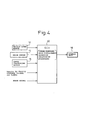
- FIG 4 is a diagram showing the configuration of an apparatus for detecting an upward/downward axis displacement in a vehicle-mounted radar according to the second embodiment of the present invention.
- a vehicle speed sensor 12 generates output pulses the number of which per unit time is proportional to the rotational speed of the transmission shaft of the vehicle, that is, the vehicle speed.
- a radar sensor 14 is a sensor, such as a millimeter-wave radar, for measuring the distance to a target.
- a curve calculating sensor 16 comprises a yaw rate sensor or the like that detects the angular velocity (yaw rate) of the vehicle about a vertical axis, and is used to calculate the radius of a curve.
- the beam from the radar sensor can be projected toward a target such as a vehicle traveling ahead, even when the radar-equipped vehicle is traveling around a curve.
- An ECU (Electronic Control Unit) 30 comprises a CPU (Central Processing Unit), memory, etc. and performs the following calculation operations for upward/downward axis displacement detection based on. the output signals of the vehicle speed sensor 12, the radar sensor 14, and the curve calculating sensor 16, on a set signal for initiating vehicle-to-vehicle distance control for causing the radar-equipped vehicle to follow a vehicle traveling ahead in the same lane while measuring the distance to the vehicle ahead, and on a brake signal indicating the braking condition of the radar-equipped vehicle.
- a display unit 18 is an output device for displaying diagnosis results, such as the result of the upward/downward axis displacement detection, under instruction from the ECU 30.
- Figures 5A to 5C are diagrams showing the relationship between the radar area of the radar sensor 14 mounted on the vehicle 20 and a stationary object 22 located above the road:
- Figure 5A shows the state in which the axis is not displaced
- Figure 5B shows the state in which the axis is displaced in the upward direction
- Figure 5C shows the state in which the axis is displaced in the downward direction.
- Figures 6A to 6C show the detection distance for the stationary object 22 as shown in Figures 6A to 6C.
- Figures 5A to 5C that is, Figure 6A shows the state in which the axis is not displaced
- Figure 6B shows the state in which the axis is displaced in the upward direction
- Figure 6C shows the state in which the axis is displaced in the downward direction.
- the stationary object 22 can be detected up to a point closer to the stationary object 22 than when the axis is not displaced, and as a result, the minimum detection distance becomes shorter.
- a histogram showing their relative frequencies can be drawn, depicting the differences between the case of no axis displacement, the case of upward axis displacement, and the case of downward axis displacement, as shown in Figure 7.
- the frequency is lower in the shorter minimum detection distance segment, while when the axis is displaced in the upward or downward direction, the frequency is higher in the shorter minimum detection distance segment.
- a threshold value "b" for determining the presence or absence of an upward/downward axis displacement can be set in advance as shown in Figure 7.
- the ECU 30 gathers data on its minimum detection distance.
- the ECU 30 calculates, based on the gathered data, the frequency with which the minimum detection distance becomes smaller than the threshold value "a”. Then, if the frequency is higher than the threshold value "b", the ECU 30 determines that the axis is displaced in the upward or downward direction.
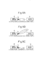
- Figures 8A to 8C are diagrams showing the relationship between the radar area of the radar sensor 14 mounted on the vehicle 20 and another vehicle (vehicle traveling in front) 24 as a moving object: Figure 8A shows the state in which the axis is not displaced, Figure 8B shows the state in which the axis is displaced in the upward direction, and Figure 8C shows the state in which the axis is displaced in the downward direction.
- Figures 9A to 9C show the detection distance for the vehicle 24 in front changes with time as shown in Figures 9A to 9C.
- Figures 8A to 8C that is, Figure 9A shows the state in which the axis is not displaced, Figure 9B shows the state in which the axis is displaced in the upward direction, and Figure 9C shows the state in which the axis is displaced in the downward direction.
- Figure 9A shows the state in which the axis is not displaced
- Figure 9B shows the state in which the axis is displaced in the upward direction
- Figure 9C shows the state in which the axis is displaced in the downward direction.
- the vehicle 24 in front goes out of the detection range earlier than when the axis is not displaced and, as a result, the maximum detection distance becomes shorter.
- the same can be said of the maximum detection distance when the distance of the vehicle 24 relative to the vehicle 20 decreases.
- a histogram showing their relative frequencies can be drawn, depicting the differences between the case of no axis displacement, the case of upward axis displacement, and the case of downward axis displacement, as shown in Figure 10.
- the frequency is lower in the shorter maximum detection distance segment, while when the axis is displaced in the upward or downward direction, the frequency is higher in the shorter maximum detection distance segment.
- a threshold value "b" for determining the presence or absence of an upward/downward axis displacement can be set in advance as shown in Figure 10.
- the ECU 30 gathers data on its maximum detection distance.
- the ECU 30 calculates, based on the gathered data, the frequency with which the maximum detection distance becomes smaller than the threshold value "a”. Then, if the frequency is higher than the threshold value "b", the ECU 30 determines that the axis is displaced in the upward or downward direction.
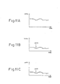
- the average values can be plotted, depicting the differences between the case of no axis displacement and the case of upward/downward axis displacement, as shown in Figure 12.
- a threshold value for determining the presence or absence of an upward/downward axis displacement can be set in advance for the average level.
- the ECU 30 calculates the average value of the reflection levels for each distance segment over a predetermined time. When the calculated average value is smaller than the threshold value, the ECU 30 determines that the axis is displaced in the upward or downward direction.
- Figures 13A to 13C a flag indicating the occurrence of a vehicle-to-vehicle distance control setting operation or a braking operation changes as shown in Figures 13A to 13C with respect to time.
- Figures 8A to 8C that is, Figure 13A shows the state in which the axis is not displaced, Figure 13B shows the state in which the axis is displaced in the upward direction, and Figure 13C shows the state in which the axis is displaced in the downward direction.
- Figure 13A shows the state in which the axis is not displaced
- Figure 13B shows the state in which the axis is displaced in the upward direction
- Figure 13C shows the state in which the axis is displaced in the downward direction.
- the vehicle-to-vehicle distance control setting operation or the braking operation is performed more frequently than when the axis is not displaced.
- the ECU 30 detects the control re-setting operation or the braking operation for a predetermined period of time.
- the ECU 30 determines that the axis is displaced in the upward or downward direction.
- an apparatus for detecting an upward/downward axis displacement, in a simple and accurate manner, in a vehicle-mounted radar is provided.
Landscapes
- Engineering & Computer Science (AREA)
- Radar, Positioning & Navigation (AREA)
- Remote Sensing (AREA)
- Physics & Mathematics (AREA)
- Computer Networks & Wireless Communication (AREA)
- General Physics & Mathematics (AREA)
- Electromagnetism (AREA)
- Radar Systems Or Details Thereof (AREA)
- Optical Radar Systems And Details Thereof (AREA)
Abstract
Description
Claims (11)
- A road surface detection apparatus, mounted on a vehicle, for gathering information about a road surface, comprising:transmitting/receiving means for projecting a radar beam signal onto the road surface on which the vehicle is traveling, and for receiving a signal containing a reflected signal of the radar beam signal; andaxis displacement determining means for comparing the level of the reflected signal, reflected from the road surface and contained in the signal received by the transmitting/receiving means, with a predetermined reference level and, if the result of the comparison lies outside a predefined range, then determining that an axis defining the projection direction of the radar beam signal is displaced.
- A road surface detection apparatus, mounted on a vehicle, for gathering information about a road surface by projecting a radar beam signal onto the road surface on which the vehicle is traveling, and by receiving a signal containing a reflected signal of the radar beam signal reflected from the road surface, the apparatus comprising:road surface signal detecting means for detecting the reflected signal reflected from the road surface and contained in the received signal;storage means for pre-storing as a reference level the reception level of the reflected signal reflected from the road surface and detected by the road surface signal detecting means when there is no axis displacement in the projection direction of the radar beam signal; andaxis displacement determining means for comparing, when the vehicle is traveling, the reception level of the reflected signal reflected from the road surface and detected by the road surface signal detecting means with the reference level stored in the storage means and, if the result of the comparison lies outside a predefined range, then determining that an axis defining the projection direction of the radar beam signal is displaced.
- A road surface detection apparatus as claimed in claim 2 wherein, when the reception level detected by the road surface signal detecting means has been outside the predefined range on the higher side of the reference level for a predetermined period of time, the axis displacement determining means determines that the axis is displaced in a downward direction.
- A road surface detection apparatus as claimed in claim 3 wherein, when the reception level detected by the road surface signal detecting means has been equal to or higher than a road surface outside level preset at a higher point than the predefined range for the predetermined period of time, the axis displacement determining means determines that the reception level is for a signal reflected from an object other than the road surface, and does not determine that the axis is displaced in the downward direction.
- A road surface detection apparatus as claimed in any one of claims 2 to 4 wherein, when the reception level detected by the road surface signal detecting means has been outside the predefined range on the lower side of the reference level for the predetermined period of time, the axis displacement determining means determines that the axis is displaced in an upward direction.
- A road surface detection apparatus as claimed in any one of claims 2 to 5, further including gradient detecting means for detecting the gradient of the road on which the vehicle is traveling and wherein,
when performing the axis displacement determination, the axis displacement determining means compares the reception level detected by the road surface signal detecting means with the reference level after correcting the reception level based on the gradient of the road detected by the gradient detecting means. - A road surface detection apparatus as claimed in any one of claims 2 to 6, wherein the axis displacement determining means stores the result of the axis displacement determination in the storage means.
- An apparatus for detecting an axis displacement in an upward or downward direction for a radar mounted on a vehicle, comprising:means for gathering data on a minimum detection distance for an overhead stationary object detected by the radar;means for calculating, based on the gathered data, the frequency with which the minimum detection distance is less than a first threshold value; andmeans for determining that the axis of the radar is displaced in the upward or downward direction, if the frequency is higher than a second threshold value.
- An apparatus for detecting an axis displacement in an upward or downward direction for a radar mounted on a vehicle, comprising:means for gathering data on a maximum detection distance for a moving object detected by the radar;means for calculating, based on the gathered data, the frequency with which the maximum detection distance is less than a first threshold value; andmeans for determining that the axis of the radar is displaced in the upward or downward direction, if the frequency is higher than a second threshold value.
- An apparatus for detecting an axis displacement in an upward or downward direction for a radar mounted on a vehicle, comprising:means for calculating an average value of reflection levels for a moving object detected by the radar, the average value being calculated for each prescribed distance range over a predetermined period of time; andmeans for determining that the axis of the radar is displaced in the upward or downward direction, if the calculated average value is less than a predetermined threshold value.
- An apparatus for detecting an axis displacement in an upward or downward direction for a radar mounted on a vehicle, comprising:means for detecting a control re-setting operation or a braking operation during vehicle-to-vehicle distance control performed using the radar; andmeans for determining that the axis of the radar is displaced in the upward or downward direction, if the frequency of the re-setting operation or braking operation detected is higher than a predetermined threshold value.
Applications Claiming Priority (3)
| Application Number | Priority Date | Filing Date | Title |
|---|---|---|---|
| JP2000398878A JP4740449B2 (en) | 2000-12-27 | 2000-12-27 | Vertical axis deviation detection device for automotive radar |
| JP2000398878 | 2000-12-27 | ||
| PCT/JP2001/011302 WO2002054105A1 (en) | 2000-12-27 | 2001-12-21 | Pavement detector and vertical axial shift detector of on board radar |
Publications (3)
| Publication Number | Publication Date |
|---|---|
| EP1348977A1 true EP1348977A1 (en) | 2003-10-01 |
| EP1348977A4 EP1348977A4 (en) | 2005-01-05 |
| EP1348977B1 EP1348977B1 (en) | 2008-02-27 |
Family
ID=18863751
Family Applications (1)
| Application Number | Title | Priority Date | Filing Date |
|---|---|---|---|
| EP01272839A Expired - Lifetime EP1348977B1 (en) | 2000-12-27 | 2001-12-21 | Pavement detector and vertical axial shift detector of on board radar |
Country Status (6)
| Country | Link |
|---|---|
| US (1) | US6896082B2 (en) |
| EP (1) | EP1348977B1 (en) |
| JP (1) | JP4740449B2 (en) |
| KR (1) | KR100660583B1 (en) |
| DE (1) | DE60133043T2 (en) |
| WO (1) | WO2002054105A1 (en) |
Families Citing this family (43)
| Publication number | Priority date | Publication date | Assignee | Title |
|---|---|---|---|---|
| EP1467223B1 (en) * | 2002-01-18 | 2007-09-12 | Hitachi, Ltd. | Radar device |
| US6927699B2 (en) | 2002-12-05 | 2005-08-09 | Denso Corporation | Object recognition apparatus for vehicle, and inter-vehicle distance control unit |
| JP2004226158A (en) * | 2003-01-21 | 2004-08-12 | Fujitsu Ten Ltd | Fm-cw radar device |
| JP3994941B2 (en) * | 2003-07-22 | 2007-10-24 | オムロン株式会社 | Radar equipment for vehicles |
| JP2005043080A (en) * | 2003-07-23 | 2005-02-17 | Fujitsu Ten Ltd | Method of attaching radar for vehicle, and radar for vehicle |
| DE102004008866A1 (en) * | 2004-02-20 | 2005-09-08 | Daimlerchrysler Ag | Method for signal evaluation of an environmental sensor of a motor vehicle |
| EP1584946A3 (en) * | 2004-04-02 | 2006-03-22 | Omron Corporation | Method of adjusting monitor axis of optical sensors |
| GB0411097D0 (en) * | 2004-05-19 | 2004-06-23 | Qinetiq Ltd | Laser radar device and method |
| JP2007051888A (en) * | 2005-08-16 | 2007-03-01 | Mitsubishi Electric Corp | Radar equipment |
| JP2007178183A (en) * | 2005-12-27 | 2007-07-12 | Mazda Motor Corp | Vehicle obstacle detection device |
| DE102006058303A1 (en) * | 2006-12-11 | 2008-06-12 | Robert Bosch Gmbh | Method for detecting a vertical misalignment of a radar sensor |
| DE102006058305A1 (en) * | 2006-12-11 | 2008-06-12 | Robert Bosch Gmbh | Method for detecting a vertical misalignment of a radar sensor |
| KR100839927B1 (en) * | 2007-02-08 | 2008-06-20 | 조용성 | Driving vehicle marking system using laser |
| US8285447B2 (en) * | 2007-03-20 | 2012-10-09 | Enpulz, L.L.C. | Look ahead vehicle suspension system |
| US7546765B1 (en) * | 2008-03-20 | 2009-06-16 | Gm Global Technology Operations, Inc. | Scanning device and method for analyzing a road surface |
| JP5168640B2 (en) * | 2008-05-12 | 2013-03-21 | トヨタ自動車株式会社 | Radar device |
| US8212660B2 (en) * | 2008-06-23 | 2012-07-03 | Frank Nugent | Overhead obstacle avoidance system |
| US8344940B2 (en) * | 2009-01-22 | 2013-01-01 | Mando Corporation | Apparatus and sensor for adjusting sensor vertical alignment |
| KR101053855B1 (en) * | 2009-01-22 | 2011-08-03 | 주식회사 만도 | Sensor vertical alignment regulator and sensor |
| US8207836B2 (en) * | 2009-06-23 | 2012-06-26 | Frank Nugent | Overhead obstacle avoidance system |
| DE102010051493B4 (en) * | 2009-12-31 | 2017-02-23 | Mando Corporation | Device for adjusting a vertical sensor orientation |
| EP2614970A1 (en) * | 2010-09-10 | 2013-07-17 | Toyota Jidosha Kabushiki Kaisha | Suspension system |
| JP5760425B2 (en) * | 2010-12-17 | 2015-08-12 | 富士通株式会社 | Control device, radar detection system, radar detection method |
| US20130154871A1 (en) * | 2011-12-14 | 2013-06-20 | Ford Global Technologies, Llc | Tilt sensing system for automotive radar |
| KR101380888B1 (en) * | 2012-07-24 | 2014-04-02 | 현대모비스 주식회사 | Apparatus and Method for Calculating Vehicle-Distance |
| JP5905846B2 (en) * | 2013-03-29 | 2016-04-20 | 株式会社日本自動車部品総合研究所 | Crossing determination device and program |
| JP6464241B2 (en) * | 2013-06-03 | 2019-02-06 | 株式会社デンソー | Radar apparatus and program |
| JP6321448B2 (en) * | 2013-06-03 | 2018-05-09 | 株式会社デンソー | Radar apparatus and program |
| JP6413097B2 (en) * | 2014-02-05 | 2018-10-31 | パナソニックIpマネジメント株式会社 | Object detection device |
| KR102214332B1 (en) * | 2014-04-30 | 2021-02-10 | 주식회사 만도 | System for making a driver operate a car easily method for determining abnormality vertical angle of radar sensor at system for making a driver operate a car easily |
| DE102014017912B3 (en) * | 2014-12-04 | 2016-02-18 | Audi Ag | Method for self-diagnosis of an environmental sensor of a motor vehicle and motor vehicle |
| US20160223649A1 (en) * | 2015-01-30 | 2016-08-04 | Robert Bosch Gmbh | Systems and methods for radar vertical misalignment detection |
| JP6169119B2 (en) * | 2015-03-09 | 2017-07-26 | 三菱電機株式会社 | Ranging device and method for detecting performance degradation of ranging device |
| JP2017227468A (en) | 2016-06-20 | 2017-12-28 | 株式会社デンソーテン | Radar device and vertical axis deviation detection method |
| JP6622167B2 (en) * | 2016-09-26 | 2019-12-18 | 株式会社デンソー | Axis deviation estimation device |
| US10852423B2 (en) * | 2018-03-07 | 2020-12-01 | The Government Of The United States, As Represented By The Secretary Of The Army | Vehicle-mounted wave transmission and wave response reception |
| US11333767B2 (en) | 2019-04-03 | 2022-05-17 | Caterpillar Inc. | Avoidance modifier system for collision avoidance system |
| JP7252110B2 (en) | 2019-10-09 | 2023-04-04 | 株式会社Soken | Axial misalignment estimator |
| JP7252111B2 (en) | 2019-10-09 | 2023-04-04 | 株式会社Soken | estimation device |
| JP7477329B2 (en) * | 2020-03-18 | 2024-05-01 | 株式会社Soken | Axis offset estimation device |
| KR102859813B1 (en) * | 2020-05-08 | 2025-09-16 | 주식회사 에이치엘클레무브 | Apparatus and Method for Detecting Vertical Misalignment of Radar Apparatus, and Radar Apparatus with the same |
| KR20220045736A (en) * | 2020-10-06 | 2022-04-13 | 광주과학기술원 | Data processing method and lidar system that can be detecting road surface |
| JP2022122197A (en) * | 2021-02-09 | 2022-08-22 | 株式会社アイシン | Object detection device and movable body control unit |
Family Cites Families (14)
| Publication number | Priority date | Publication date | Assignee | Title |
|---|---|---|---|---|
| JPS56665A (en) * | 1979-06-15 | 1981-01-07 | Nissan Motor Co Ltd | Protective device of ground speed radar for vehicle |
| JPH05223918A (en) * | 1991-12-17 | 1993-09-03 | Mitsubishi Electric Corp | Signal processor |
| JP3082555B2 (en) | 1994-01-19 | 2000-08-28 | トヨタ自動車株式会社 | In-vehicle radar device |
| JPH08292260A (en) * | 1995-04-25 | 1996-11-05 | Matsushita Electric Works Ltd | Photoelectric sensor having self-diagnostic function |
| JP3331882B2 (en) * | 1995-12-27 | 2002-10-07 | 株式会社デンソー | Central axis deflection amount calculating device, central axis deflection amount correcting device, and inter-vehicle control device of vehicle obstacle detection device |
| DE19650863C1 (en) * | 1996-12-07 | 1998-04-16 | Bosch Gmbh Robert | Method of detecting distance sensor vertical adjustment error |
| JP3930110B2 (en) | 1997-08-11 | 2007-06-13 | 富士重工業株式会社 | Vehicle cruise control device |
| JPH11109030A (en) * | 1997-10-01 | 1999-04-23 | Fujitsu Ten Ltd | Onboard radar equipment |
| JP3428009B2 (en) * | 1998-07-03 | 2003-07-22 | トヨタ自動車株式会社 | Radar equipment for vehicles |
| DE19860633A1 (en) * | 1998-12-29 | 2000-07-06 | Valeo Schalter & Sensoren Gmbh | Method of measuring the speed of a vehicle |
| SE9902141L (en) | 1999-06-08 | 2000-12-09 | Celsiustech Electronics Ab | Procedure in a radar system |
| DE19937723C2 (en) * | 1999-08-10 | 2001-10-04 | Bosch Gmbh Robert | Method and device for determining a height angle error of a multi-beam radar sensor |
| FR2798196B1 (en) * | 1999-09-07 | 2001-11-30 | Thomson Csf | METHOD AND DEVICE FOR ALIGNING A MOTOR RADAR |
| EP1231480B1 (en) * | 2001-02-08 | 2006-06-21 | Fujitsu Ten Limited | Method and device for aligning radar mount direction, and radar aligned by the method or device |
-
2000
- 2000-12-27 JP JP2000398878A patent/JP4740449B2/en not_active Expired - Lifetime
-
2001
- 2001-12-21 EP EP01272839A patent/EP1348977B1/en not_active Expired - Lifetime
- 2001-12-21 DE DE60133043T patent/DE60133043T2/en not_active Expired - Lifetime
- 2001-12-21 WO PCT/JP2001/011302 patent/WO2002054105A1/en not_active Ceased
- 2001-12-21 US US10/181,743 patent/US6896082B2/en not_active Expired - Lifetime
- 2001-12-21 KR KR1020027009809A patent/KR100660583B1/en not_active Expired - Lifetime
Also Published As
| Publication number | Publication date |
|---|---|
| DE60133043D1 (en) | 2008-04-10 |
| KR100660583B1 (en) | 2006-12-21 |
| DE60133043T2 (en) | 2009-03-19 |
| JP4740449B2 (en) | 2011-08-03 |
| US20020189875A1 (en) | 2002-12-19 |
| WO2002054105A1 (en) | 2002-07-11 |
| EP1348977B1 (en) | 2008-02-27 |
| JP2002202360A (en) | 2002-07-19 |
| US6896082B2 (en) | 2005-05-24 |
| KR20020074485A (en) | 2002-09-30 |
| EP1348977A4 (en) | 2005-01-05 |
Similar Documents
| Publication | Publication Date | Title |
|---|---|---|
| US6896082B2 (en) | Road surface detection apparatus and apparatus for detecting upward/downward axis displacement of vehicle-mounted radar | |
| EP3430422B1 (en) | System and method for detecting blockage in an automotive radar | |
| JP3797277B2 (en) | Radar | |
| US7151479B2 (en) | Radar sensor for motor vehicles | |
| JP6203862B2 (en) | Method for maintaining a warning signal in a vehicle based on the presence of a target in a warning area, in particular a blind spot, a corresponding driver assistance system and a vehicle | |
| JP3385304B2 (en) | Automotive radar equipment | |
| EP1369705B1 (en) | Signal processing method for scanning radar | |
| EP1326087B1 (en) | Apparatus and method for radar data processing | |
| CN109031271B (en) | FMCW radar sensor for motor vehicles | |
| US7786926B2 (en) | Radar system for motor vehicles | |
| CN111796243B (en) | Method for determining an offset of a radar sensor | |
| JPH09222477A (en) | Automotive radar equipment | |
| WO2013146375A1 (en) | Vehicle-mounted radar device and target detection method thereof | |
| JP6294853B2 (en) | Radar apparatus and radar apparatus control method | |
| JPH09288178A (en) | In-vehicle monopulse radar device | |
| JP2014115119A (en) | Object detector | |
| JP3635228B2 (en) | Scanning radar signal processing method | |
| US9157995B2 (en) | Radar apparatus | |
| JP2017198715A (en) | Radar apparatus and radar apparatus control method | |
| JP2017134012A (en) | Vehicle detection device, vehicle detection device control method and vehicle detection program | |
| JP4223661B2 (en) | Road surface detection device | |
| JP2005069739A (en) | On-vehicle obstacle detection device | |
| EP3690479A1 (en) | Radar device and object detection method | |
| JP2003294838A (en) | In-vehicle radar device and in-vehicle processing device |
Legal Events
| Date | Code | Title | Description |
|---|---|---|---|
| PUAI | Public reference made under article 153(3) epc to a published international application that has entered the european phase |
Free format text: ORIGINAL CODE: 0009012 |
|
| 17P | Request for examination filed |
Effective date: 20020808 |
|
| AK | Designated contracting states |
Kind code of ref document: A1 Designated state(s): AT BE CH CY DE DK ES FI FR GB GR IE IT LI LU MC NL PT SE TR |
|
| RBV | Designated contracting states (corrected) |
Designated state(s): DE FR GB |
|
| A4 | Supplementary search report drawn up and despatched |
Effective date: 20041117 |
|
| GRAP | Despatch of communication of intention to grant a patent |
Free format text: ORIGINAL CODE: EPIDOSNIGR1 |
|
| GRAS | Grant fee paid |
Free format text: ORIGINAL CODE: EPIDOSNIGR3 |
|
| GRAA | (expected) grant |
Free format text: ORIGINAL CODE: 0009210 |
|
| AK | Designated contracting states |
Kind code of ref document: B1 Designated state(s): DE FR GB |
|
| REG | Reference to a national code |
Ref country code: GB Ref legal event code: FG4D |
|
| REF | Corresponds to: |
Ref document number: 60133043 Country of ref document: DE Date of ref document: 20080410 Kind code of ref document: P |
|
| ET | Fr: translation filed | ||
| PLBE | No opposition filed within time limit |
Free format text: ORIGINAL CODE: 0009261 |
|
| STAA | Information on the status of an ep patent application or granted ep patent |
Free format text: STATUS: NO OPPOSITION FILED WITHIN TIME LIMIT |
|
| 26N | No opposition filed |
Effective date: 20081128 |
|
| REG | Reference to a national code |
Ref country code: FR Ref legal event code: PLFP Year of fee payment: 15 |
|
| REG | Reference to a national code |
Ref country code: FR Ref legal event code: PLFP Year of fee payment: 16 |
|
| REG | Reference to a national code |
Ref country code: FR Ref legal event code: PLFP Year of fee payment: 17 |
|
| PGFP | Annual fee paid to national office [announced via postgrant information from national office to epo] |
Ref country code: FR Payment date: 20201223 Year of fee payment: 20 Ref country code: GB Payment date: 20201223 Year of fee payment: 20 Ref country code: DE Payment date: 20201211 Year of fee payment: 20 |
|
| REG | Reference to a national code |
Ref country code: DE Ref legal event code: R071 Ref document number: 60133043 Country of ref document: DE |
|
| REG | Reference to a national code |
Ref country code: GB Ref legal event code: PE20 Expiry date: 20211220 |
|
| PG25 | Lapsed in a contracting state [announced via postgrant information from national office to epo] |
Ref country code: GB Free format text: LAPSE BECAUSE OF EXPIRATION OF PROTECTION Effective date: 20211220 |