EP1348921A2 - Refrigerant distributor and air conditioner using the same - Google Patents
Refrigerant distributor and air conditioner using the same Download PDFInfo
- Publication number
- EP1348921A2 EP1348921A2 EP02254634A EP02254634A EP1348921A2 EP 1348921 A2 EP1348921 A2 EP 1348921A2 EP 02254634 A EP02254634 A EP 02254634A EP 02254634 A EP02254634 A EP 02254634A EP 1348921 A2 EP1348921 A2 EP 1348921A2
- Authority
- EP
- European Patent Office
- Prior art keywords
- refrigerant
- distributor
- orifice
- fine particle
- conversion means
- Prior art date
- Legal status (The legal status is an assumption and is not a legal conclusion. Google has not performed a legal analysis and makes no representation as to the accuracy of the status listed.)
- Granted
Links
Images

Classifications
-
- F—MECHANICAL ENGINEERING; LIGHTING; HEATING; WEAPONS; BLASTING
- F25—REFRIGERATION OR COOLING; COMBINED HEATING AND REFRIGERATION SYSTEMS; HEAT PUMP SYSTEMS; MANUFACTURE OR STORAGE OF ICE; LIQUEFACTION SOLIDIFICATION OF GASES
- F25B—REFRIGERATION MACHINES, PLANTS OR SYSTEMS; COMBINED HEATING AND REFRIGERATION SYSTEMS; HEAT PUMP SYSTEMS
- F25B39/00—Evaporators; Condensers
- F25B39/02—Evaporators
-
- F—MECHANICAL ENGINEERING; LIGHTING; HEATING; WEAPONS; BLASTING
- F25—REFRIGERATION OR COOLING; COMBINED HEATING AND REFRIGERATION SYSTEMS; HEAT PUMP SYSTEMS; MANUFACTURE OR STORAGE OF ICE; LIQUEFACTION SOLIDIFICATION OF GASES
- F25B—REFRIGERATION MACHINES, PLANTS OR SYSTEMS; COMBINED HEATING AND REFRIGERATION SYSTEMS; HEAT PUMP SYSTEMS
- F25B41/00—Fluid-circulation arrangements
- F25B41/40—Fluid line arrangements
- F25B41/42—Arrangements for diverging or converging flows, e.g. branch lines or junctions
- F25B41/45—Arrangements for diverging or converging flows, e.g. branch lines or junctions for flow control on the upstream side of the diverging point, e.g. with spiral structure for generating turbulence
-
- F—MECHANICAL ENGINEERING; LIGHTING; HEATING; WEAPONS; BLASTING
- F25—REFRIGERATION OR COOLING; COMBINED HEATING AND REFRIGERATION SYSTEMS; HEAT PUMP SYSTEMS; MANUFACTURE OR STORAGE OF ICE; LIQUEFACTION SOLIDIFICATION OF GASES
- F25B—REFRIGERATION MACHINES, PLANTS OR SYSTEMS; COMBINED HEATING AND REFRIGERATION SYSTEMS; HEAT PUMP SYSTEMS
- F25B43/00—Arrangements for separating or purifying gases or liquids; Arrangements for vaporising the residuum of liquid refrigerant, e.g. by heat
-
- F—MECHANICAL ENGINEERING; LIGHTING; HEATING; WEAPONS; BLASTING
- F25—REFRIGERATION OR COOLING; COMBINED HEATING AND REFRIGERATION SYSTEMS; HEAT PUMP SYSTEMS; MANUFACTURE OR STORAGE OF ICE; LIQUEFACTION SOLIDIFICATION OF GASES
- F25B—REFRIGERATION MACHINES, PLANTS OR SYSTEMS; COMBINED HEATING AND REFRIGERATION SYSTEMS; HEAT PUMP SYSTEMS
- F25B39/00—Evaporators; Condensers
- F25B39/02—Evaporators
- F25B39/028—Evaporators having distributing means
Definitions
- the present invention relates to a refrigerant distributor and an air conditioner using the same.
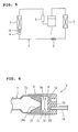
- Fig. 5 is a schematic block diagram showing a common refrigerant circuit of an air conditioner of the kind disclosed, for example, in the Japanese Patent Laid-Open Publication No. Hei. 10-253196.
- reference numeral 1 denotes a compressor, 2 an outdoor heat exchanger (condenser), 3 a pressure reduction capillary tube (pressure reduction device), 4 a refrigerant distributor, 5 an indoor heat exchanger (evaporator), 6 an accumulator, and 7 refrigerant pipes.
- the refrigerant circuit is constituted by connecting, one by one with the refrigerant pipes 7, the compressor 1, the outdoor heat exchanger 2, the pressure reduction capillary tube 3, the refrigerant distributor 4, the indoor heat exchanger 5, and the accumulator 6.
- Fig. 6 is a side cross-sectional view of a conventional refrigerant distributor of an air conditioner.
- reference numeral 7a denotes a distributor refrigerant-pipe and 8 denotes a refrigerant-distributor main body having distributor holes and a gas-liquid mixing chamber 9.
- Reference numeral 10 denotes an orifice member having a conical orifice 10a with a cross-sectional area gradually reducing toward an end of the orifice so as to increase of a contracted refrigerant flow through the orifice.
- a flat-plate orifice 11 is arranged at an end of the orifice member on the side of the gas-liquid mixing chamber 9.
- the distributor refrigerant-pipe 7a is inserted into a bore of the refrigerant-distributor main body 8, and the orifice member 10 and the flat-plate orifice 11 are sandwiched and fixed between an end face of the distributor refrigerant-pipe 7a and a stepped portion of the bore of the refrigerant-distributor main body 8.
- Reference numeral 12 denotes a fine particle conversion mean having a large number of holes, which divides the gas-liquid mixing chamber 9 into a first gas-liquid mixing chamber 9a and a second gas-liquid mixing chamber 9b, and is formed, for example, of a cage-formed steel net.
- Reference numeral 13 denotes a plurality of distribution holes formed in the refrigerant-distributor main body 8 and connected to the second gas-liquid mixing chamber 9b.
- Reference numeral 14 denotes a distribution pipe inserted into a distribution hole 13.
- a gaseous refrigerant with high temperature and high pressure compressed and discharged by the compressor 1 is condensed through the exchange of heat with the outdoor air to turn into a liquid refrigerant with high pressure, while passing through the outdoor heat exchanger 2.
- the refrigerant is rapidly reduced in pressure and expanded to turn into a gas-liquid two-phase refrigerant with low pressure while the refrigerant passes through the pressure reduction capillary tube 3.
- the refrigerant is then distributed by the refrigerant distributor 4 and the distribution pipe 14 and sent to respective refrigerant flow passages of the indoor heat exchanger 5.
- the gas-liquid two-phase refrigerant evaporates through the exchange of heat with the indoor air to turn into a gaseous refrigerant with low pressure.
- the gaseous refrigerant with low pressure flows through the accumulator 6, and is sucked by the compressor 1. Then, the refrigerant is again compressed and discharged, thereby the same operation is repeated in this refrigerant flow passage.
- the low pressure gas-liquid two phase refrigerant first passes through the distributor refrigerant-pipe 7a, and its flow is contracted by the conical orifice 10a and then discharged into the gas-liquid mixing portion 9 to uniformly mix the gaseous portion and liquid portion of the gas-liquid two-phase refrigerant, so that the gas-liquid two-phase refrigerant is made homogeneous.
- the refrigerant is then led to the distribution pipe 14 to be equally distributed.
- the conical orifice 10a gradually increases flow speed of the gas-liquid two-phase refrigerant so that rapid pressure drop of the refrigerant is prevented. Further, through the flat-plate orifice 11 arranged at the outlet of the conical orifice 10a, the gas-liquid two-phase refrigerant is discharged into the first gas-liquid mixing chamber 9a, so that its flow speed becomes a maximum value, and the difference in flow speed between the gaseous portion and liquid portion of the gas-liquid two-phase refrigerant becomes a minimum value. The gaseous and liquid portions of the refrigerant are diffused and mixed, there. After that, the liquid portion of the refrigerant is made finer in size by the steel net 12 as the fine particle conversion means, and the finer refrigerant liquid for distribution is distributed from the second gas-liquid mixing chamber 9b to each of the distribution holes 13.
- the conventional refrigerant distributor of an air conditioner is, as described above, basically constituted by a plurality of parts including the distributor refrigerant-pipe 7a, the refrigerant-distributor main body 8, the conical orifice 10a, the flat plate orifice 11, and the steel net 12 that are not unified together. Therefore, a problem has occurred, where individual parts become loose and collision sounds are generated between them while the refrigerant flows.
- An object of the invention is to further promote the fixing and unifying of parts constituting a refrigerant distributor to prevent generation of collision sounds between the parts while a refrigerant flows.
- a refrigerant distributor arranged between a pressure reduction device and an evaporator in a refrigerant circuit comprises; a distributor refrigerant-pipe, an orifice member which is received in the distributor refrigerant-pipe and has an orifice for increasing flow speed of refrigerant introduced from the distributor refrigerant-pipe, a fine particle conversion means for converting liquid droplets included in the refrigerant having the flow speed increased by the orifice, into finer particles, and a refrigerant-distributor main body which is externally fitted on the refrigerant pipe and has distribution holes for distributing the refrigerant including the liquid droplets converted into finer particles by the fine particle conversion means, that are arranged in order in a flow direction of the refrigerant.
- the orifice member is firmly fixed to and unified with the fine particle conversion means, and the orifice member unified with the fine particle conversion means
- the orifice member has at its one end a short outer tube in a monolithic structure, the orifice is formed as a conical orifice having a cross-sectional area gradually reducing toward an end of the orifice so that a speed of a contracted refrigerant flow through the orifice is increased, the fine particle conversion means is constituted by a cage-formed member having a large number of holes, the orifice member is firmly fixed to and unified with the fine particle conversion means in such a manner that an edge portion of the fine particle conversion means is sandwiched between the inner periphery of the short outer tube and the outer periphery of an inner tube constituted by a main body of the orifice member.
- the orifice member unified with the fine particle conversion means is firmly fixed to and unified with the distributor refrigerant-pipe by swaging an edge of the distributor refrigerant-pipe from outside with the short outer tube of the orifice member.
- annular projection portions are provided on the inner periphery of the short outer tube and the outer periphery of the inner tube of the orifice member, to be arranged at positions separated from one another in an axial direction of the tubes, so that the edge portion of the fine particle conversion means is sandwiched by the annular projection portions in a labyrinth form, and fixed to the orifice member firmly.
- an air conditioner using the refrigerant distributor of the present invention is constituted as described below. That is, as set forth in claim 4, in an air conditioner having a refrigerant distributor arranged between a pressure reduction device and an evaporator in a refrigerant circuit comprising a compressor, a condenser, the pressure reduction device, and the evaporator that are connected by refrigerant pipes, the refrigerant distributor is constituted by a distributor refrigerant-pipe connected with the refrigerant-pipe, an orifice member which is received in the distributor refrigerant-pipe and has an orifice for increasing flow speed of refrigerant introduced from the distributor refrigerant-pipe, a fine particle conversion means for converting liquid droplets included in the refrigerant having the flow speed increased by the orifice into finer particles, and a refrigerant-distributor main body which is externally fitted onto the distributor refrigerant-pipe and has distribution holes for distributing the refrigerant including the liquid droplets converted into fine
- the orifice member has at its one end a short outer tube in a monolithic structure, the orifice is formed as a conical orifice with a cross-sectional area gradually reducing toward an end of the orifice so that a speed of a contracted refrigerant flow through the orifice is increased, the fine particle conversion means is constituted by a cage-formed member having a large number of holes, the orifice member is firmly fixed to and unified with the fine particle conversion means in such a manner that an edge portion of the fine particle conversion means is sandwiched between the inner periphery of the short outer tube and the outer periphery of an inner tube constituted by a main body of the orifice member. Further, the orifice member unified with the fine particle conversion means is fixed to and unified with the distributor refrigerant-pipe by swaging an edge of the distributor refrigerant-pipe from the outside with the outer tube of the orifice member
- annular projection portions are provided on the inner periphery of the short outer tube and the outer periphery of the inner tube of the orifice member to be arranged at positions separated from one another in an axial direction of the pipe.
- the edge portion of the fine particle conversion means is sandwiched by the annular projection portions in a labyrinth form and fixed to the orifice member firmly.
- Fig. 1 is a side cross-sectional view of a refrigerant distributor assembling according to a first embodiment of the invention
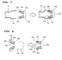
- Figs. 2 and 3 are explanatory drawings illustrating assembling procedures of parts constituting the refrigerant distributor. Parts in the figures that correspond to those in the example described above of a conventional refrigerant distributor are denoted by the same reference numerals.
- reference numeral 4A denotes a refrigerant distributor, 7A a refrigerant pipe, 7a a distributor refrigerant-pipe, 8A a refrigerant-distributor main body which is externally fitted onto the refrigerant pipe 7A and has a bore and distribution holes.
- a step portion 8a is arranged in the bore of the main body at a position halfway in an axial direction along the bore, and a gas-liquid mixing chamber 9 is formed at the deepest portion of the bore.
- Reference numeral 10A denotes an orifice member having a flange portion 10b at the outer periphery of its base end and formed as a conical orifice 10a with its inside cross-sectional area gradually reducing toward the end of the orifice so that speed of a refrigerant flow contracted by the orifice is increased.
- the flange portion 10b of the orifice member 10A is bent at its outer periphery side, toward a main body of the orifice member to form a short outer tube 10c.
- An edge portion 12a (Fig.
- a cage-formed steel net 12A as a fine particle conversion means which is provided with a large number of holes for dividing the gas-liquid mixing chamber 9 into a first gas-liquid mixing chamber 9a and a second a gas-liquid mixing chamber 9b, is sandwiched between the inner periphery of the short outer tube 10c and the outer periphery of an inner tube constituted by the main body of the orifice member and is firmly fixed to the orifice member 10A.
- the distributor refrigerant-pipe 7a is swaged, from the outside, at its end at a swage portion 7b together with the end of the outer tube 10c.
- the orifice member 10A, the steel net 12A, and the distributor refrigerant-pipe 7a are solidly fixed to each other and unified together.
- the assembly of the orifice member 10A, the steel net 12A, and the distributor refrigerant-pipe 7a that are solidly fixed to each other and unified together is further solidly fixed to the refrigerant-distributor main body 8A in such a manner that the swage portion 7b contacts with the step portion 8a in the bore of the refrigerant-distributor main body 8A, and the refrigerant-distributor main body 8A and the distributor refrigerant-pipe 7a are connected by welding 15.
- Reference numeral 13 denotes a plurality of distribution holes formed in the refrigerant-distributor main body 8A and connected through to the second gas-liquid mixing chamber 9b.
- Reference numeral 14 denotes a distribution pipe inserted into a distribution hole 13.
- the constitution and operation of a refrigerant circuit in an air conditioner using the refrigerant distributor 4A according to the invention are basically the same as those of the conventional example described above (Fig. 5), and the description thereof is omitted.
- Figs. 1 to 3 the main body of the orifice member 10A is first inserted into the cage-formed steel net 12A. Then, the flange portion 10b of the orifice member 10A is bent to form the outer tube 10c. Also at the same time, the edge portion 12a of the steel net 12A is sandwiched between the outer tube 10c and the inner tube that is formed as a part of the main body of the orifice member 10A so that a first unified part comprising the orifice member 10A and the steel net 12A firmly fixed thereto is formed.
- the first unified part described above is inserted into the distributor refrigerant-pipe 7a from the side of the flange 10b, and an end side of the distributor refrigerant-pipe 7a is swaged at the swage portion 7b, to form a second unified part comprising the first unified part and the distributor refrigerant-pipe 7a firmly fixed thereto.
- the second unified part is inserted into the refrigerant-distributor main body 8A up to the position where the swaged portion 7b contacts with the step portion 8a. Then, the distributor refrigerant-pipe 7a and the refrigerant-distributor main body 8A are welded at a weld portion 15. Thereby, a third unified part (a complete unit) comprising the second unified part and the refrigerant-distributor main body 8A firmly fixed thereto is formed.
- the constituent parts are fixed to each other and unified together in the steps of the first, second, and third unified parts, taken toward the complete unit. Therefore, when the distributor is incorporated into and used in the refrigerant circuit of an air conditioner, collisions do not occur between the respective parts while a refrigerant flows, so that generation of collision sounds is prevented.
- Fig. 4 is an explanatory drawing showing the relationship between an orifice member and a fine particle conversion means, both of which are essential elements of the refrigerant distributor according to a second embodiment of the invention. Parts in the figures that correspond to those in the first embodiment are denoted by the same reference numerals.
- the refrigerant distributor according to the embodiment is different from that of the first embodiment as follows.
- annular projection portions 10d are provided on a surface of the flange 10b, which will turn to the inner periphery of the outer tube 10c after bending, and an annular projection portion 10e is provided on the outer periphery of the inner tube constituted by the main body of the orifice member 10A.
- the annular projection portions 10d and 10e are arranged such that, when the flange 10b is bent, they are at positions separated from one another in an axial direction of the tubes.
- Fig. 4 First, as shown in Fig. 4, the main body of the orifice member 10A is inserted into the cage-formed steel net 12A. Then, the flange 10b of the orifice member 10A is bent to form the outer tube 10c, while at the same time, the edge portion 12a of the steel net 12A is sandwiched in a labyrinth form by the annular projections 10d and 10e. Thus, a first unified part comprising the orifice member 10A and the steel net 12A firmly fixed thereto is formed.
- the first unified part described above is inserted into the distributor refrigerant-pipe 7a from the side of the flange 10b, and an end side of the distributor refrigerant-pipe 7a is swaged at the swage portion 7b.
- a second unified part comprising the first unified part and the distributor refrigerant-pipe 7a firmly fixed thereto is formed.
- the second unified part is inserted into the refrigerant-distributor main body 8A up to the position where the swaged portion 7b contacts with the step portion 8a. Then, the distributor refrigerant-pipe 7a and the refrigerant-distributor main body 8A are welded at a weld portion 15. Thus, a third unified part (a complete unit) comprising the second unified part and the refrigerant-distributor main body 8A firmly fixed thereto is formed.
- the edge portion 12a of the steel net 12A is sandwiched, in a labyrinth form, by the annular projection portions 10d and 10e of the orifice member 10A so as to be more solidly fixed. Therefore, when the refrigerant distributor is incorporated into and used in the refrigerant circuit of an air conditioner, collisions do not occur between respective parts while the refrigerant flows, so that the generation of collision sounds is prevented.
- the orifice of the orifice member has a conical shape as an example.
- the shape of the orifice is not limited to a conical one, and any shape that gradually reduces its bore cross-sectional area can satisfy the requirement.
- Other shape such as a pyramid shape, for example, can also be adopted.
- the orifice member is firmly fixed to and unified with the fine particle conversion means, and the orifice member unified with the fine particle conversion means is further firmly fixed to and unified with the refrigerant pipe. Accordingly, the parts constituting the refrigerant distributor can be solidly unified together at a plurality of steps taken toward the complete unit.
- the orifice member has at its one end a short outer tube unified therewith, and is formed as a conical orifice having a cross-sectional area gradually reducing toward an end of the orifice so that a speed of a contracted refrigerant flow through the orifice is increased
- the fine particle conversion means is constituted by a cage-formed member having a large number of holes
- the orifice member and the fine particle conversion means are firmly fixed to each other and unified together in such a manner that an edge portion of the fine particle conversion means is sandwiched between the inner periphery of the outer tube of the orifice member and the outer periphery of an inner tube constituted by the main body of the orifice member
- the orifice member unified with the fine particle conversion means is firmly fixed to and unified with the distributor refrigerant-pipe by swaging the distributor refrigerant-pipe, from the outside, at its end at a swage portion together with an edge of the
- the annular projection portions are provided on the inner periphery of the outer tube of the orifice member and the outer periphery of the inner tube constituted by the orifice-member main body, so as to be arranged at positions separated from one another in an axial direction of the tube and the edge portion of the fine particle conversion means is sandwiched between the annular projection portions in a labyrinth form, so as to be firmly fixed to the orifice member. Therefore, the refrigerant distributor can be more solidly unified from the early stage of the assembling procedures of the parts.
- a refrigerant distributor is arranged between the pressure reduction device and the evaporator in a refrigerant circuit which comprises a compressor, a condenser, a pressure reduction device, and an evaporator that are connected by refrigerant pipes.
- the refrigerant distributor is constituted by an orifice member which is received in the distributor refrigerant-pipe and has an orifice for increasing flow speed of a refrigerant, fine particle conversion means for converting liquid droplets in the refrigerant with a speed increased by the orifice, into finer particles, and a refrigerant-distributor main body which is externally fitted onto the distributor refrigerant-pipe and has distribution holes for distributing the refrigerant converted to fine particles by the fine particle conversion means.
- the orifice member and the fine particle conversion means are firmly fixed to each other and unified together, and the orifice member unified with the fine particle conversion means is further firmly fixed to and unified with the distributor refrigerant-pipe. Because of the constitution described above, no collisions occur between respective parts while the refrigerant flows, so that generation of collision sounds can be prevented.
- the orifice member has at its one end a short outer tube unified therewith, and is formed as a conical orifice having a cross-sectional area gradually reducing toward an end of the orifice so that a speed of a contracted refrigerant flow through the orifice is increased
- the fine particle conversion means is constituted by a cage-formed member having a large number of holes
- the orifice member and the fine particle conversion means are firmly fixed to each other and unified together in such a manner that an edge portion of the fine particle conversion means is sandwiched between the inner periphery of the outer tube of the orifice member and the outer periphery of the inner tube constituted by the main body of the orifice member
- the orifice member unified with the fine particle conversion means is firmly fixed to and unified with the distributor refrigerant-pipe by swaging the distributor refrigerant-pipe, from the outside, at its end at a swage portion together
- the annular projection portions are provided on the inner periphery of the outer tube of the orifice member and the outer periphery of the inner tube constituted by the orifice-member main body, so as to be arranged at positions separated from one another in an axial direction of the tube.
- the edge portion of the fine particle conversion means is sandwiched, in a labyrinth form, between the annular projection portions, so as to be firmly fixed to the orifice member.
Landscapes
- Engineering & Computer Science (AREA)
- Physics & Mathematics (AREA)
- Mechanical Engineering (AREA)
- Thermal Sciences (AREA)
- General Engineering & Computer Science (AREA)
- Chemical & Material Sciences (AREA)
- Analytical Chemistry (AREA)
- Power Engineering (AREA)
- Pipe Accessories (AREA)
- Branch Pipes, Bends, And The Like (AREA)
- Air-Conditioning For Vehicles (AREA)
Abstract
Description
- The present invention relates to a refrigerant distributor and an air conditioner using the same.
- Fig. 5 is a schematic block diagram showing a common refrigerant circuit of an air conditioner of the kind disclosed, for example, in the Japanese Patent Laid-Open Publication No. Hei. 10-253196. In the figure,
reference numeral 1 denotes a compressor, 2 an outdoor heat exchanger (condenser), 3 a pressure reduction capillary tube (pressure reduction device), 4 a refrigerant distributor, 5 an indoor heat exchanger (evaporator), 6 an accumulator, and 7 refrigerant pipes. The refrigerant circuit is constituted by connecting, one by one with therefrigerant pipes 7, thecompressor 1, theoutdoor heat exchanger 2, the pressure reductioncapillary tube 3, therefrigerant distributor 4, theindoor heat exchanger 5, and the accumulator 6. - Fig. 6 is a side cross-sectional view of a conventional refrigerant distributor of an air conditioner. In the figure,
reference numeral 7a denotes a distributor refrigerant-pipe and 8 denotes a refrigerant-distributor main body having distributor holes and a gas-liquid mixing chamber 9.Reference numeral 10 denotes an orifice member having aconical orifice 10a with a cross-sectional area gradually reducing toward an end of the orifice so as to increase of a contracted refrigerant flow through the orifice. A flat-plate orifice 11 is arranged at an end of the orifice member on the side of the gas-liquid mixing chamber 9. The distributor refrigerant-pipe 7a is inserted into a bore of the refrigerant-distributormain body 8, and theorifice member 10 and the flat-plate orifice 11 are sandwiched and fixed between an end face of the distributor refrigerant-pipe 7a and a stepped portion of the bore of the refrigerant-distributormain body 8.Reference numeral 12 denotes a fine particle conversion mean having a large number of holes, which divides the gas-liquid mixing chamber 9 into a first gas-liquid mixing chamber 9a and a second gas-liquid mixing chamber 9b, and is formed, for example, of a cage-formed steel net.Reference numeral 13 denotes a plurality of distribution holes formed in the refrigerant-distributormain body 8 and connected to the second gas-liquid mixing chamber 9b.Reference numeral 14 denotes a distribution pipe inserted into adistribution hole 13. - Next, operation of a conventional air conditioner will be described below. A gaseous refrigerant with high temperature and high pressure compressed and discharged by the
compressor 1 is condensed through the exchange of heat with the outdoor air to turn into a liquid refrigerant with high pressure, while passing through theoutdoor heat exchanger 2. Next, the refrigerant is rapidly reduced in pressure and expanded to turn into a gas-liquid two-phase refrigerant with low pressure while the refrigerant passes through the pressure reductioncapillary tube 3. The refrigerant is then distributed by therefrigerant distributor 4 and thedistribution pipe 14 and sent to respective refrigerant flow passages of theindoor heat exchanger 5. The gas-liquid two-phase refrigerant evaporates through the exchange of heat with the indoor air to turn into a gaseous refrigerant with low pressure. The gaseous refrigerant with low pressure flows through the accumulator 6, and is sucked by thecompressor 1. Then, the refrigerant is again compressed and discharged, thereby the same operation is repeated in this refrigerant flow passage. - In the
refrigerant distributor 4 arranged in the refrigerant flow passage, the low pressure gas-liquid two phase refrigerant first passes through the distributor refrigerant-pipe 7a, and its flow is contracted by theconical orifice 10a and then discharged into the gas-liquid mixing portion 9 to uniformly mix the gaseous portion and liquid portion of the gas-liquid two-phase refrigerant, so that the gas-liquid two-phase refrigerant is made homogeneous. The refrigerant is then led to thedistribution pipe 14 to be equally distributed. - The
conical orifice 10a gradually increases flow speed of the gas-liquid two-phase refrigerant so that rapid pressure drop of the refrigerant is prevented. Further, through the flat-plate orifice 11 arranged at the outlet of theconical orifice 10a, the gas-liquid two-phase refrigerant is discharged into the first gas-liquid mixing chamber 9a, so that its flow speed becomes a maximum value, and the difference in flow speed between the gaseous portion and liquid portion of the gas-liquid two-phase refrigerant becomes a minimum value. The gaseous and liquid portions of the refrigerant are diffused and mixed, there. After that, the liquid portion of the refrigerant is made finer in size by thesteel net 12 as the fine particle conversion means, and the finer refrigerant liquid for distribution is distributed from the second gas-liquid mixing chamber 9b to each of thedistribution holes 13. - The conventional refrigerant distributor of an air conditioner is, as described above, basically constituted by a plurality of parts including the distributor refrigerant-
pipe 7a, the refrigerant-distributormain body 8, theconical orifice 10a, theflat plate orifice 11, and thesteel net 12 that are not unified together. Therefore, a problem has occurred, where individual parts become loose and collision sounds are generated between them while the refrigerant flows. - Besides the above-mentioned example of a conventional refrigerant distributor, other techniques are disclosed by, for example, Japanese Patent Laid-Open Publication Nos. Hei. 9-138036 and 2001-194028 in which a steel net as a fine particle conversion means is fitted under pressure into a pipe, an orifice is directly formed in a pipe or a refrigerant distributor is unified with a portion into which a steel net is fitted. However, in such disclosures, there are no proposals to fit a steel net integrally and securely in a distributor. Therefore, the refrigerant distributors in such disclosures have the same problem as the above-described example that the steel net becomes loose and generates collision sounds while the refrigerant flows.
- An object of the invention is to further promote the fixing and unifying of parts constituting a refrigerant distributor to prevent generation of collision sounds between the parts while a refrigerant flows.
- The refrigerant distributor according to the invention is constituted as described below. As set forth in
claim 1, a refrigerant distributor arranged between a pressure reduction device and an evaporator in a refrigerant circuit, comprises; a distributor refrigerant-pipe, an orifice member which is received in the distributor refrigerant-pipe and has an orifice for increasing flow speed of refrigerant introduced from the distributor refrigerant-pipe, a fine particle conversion means for converting liquid droplets included in the refrigerant having the flow speed increased by the orifice, into finer particles, and a refrigerant-distributor main body which is externally fitted on the refrigerant pipe and has distribution holes for distributing the refrigerant including the liquid droplets converted into finer particles by the fine particle conversion means, that are arranged in order in a flow direction of the refrigerant. In this constitution, the orifice member is firmly fixed to and unified with the fine particle conversion means, and the orifice member unified with the fine particle conversion means is firmly fixed to and unified with the distributor refrigerant-pipe. - In the refrigerant distributor, as set forth in
claim 2, the orifice member has at its one end a short outer tube in a monolithic structure, the orifice is formed as a conical orifice having a cross-sectional area gradually reducing toward an end of the orifice so that a speed of a contracted refrigerant flow through the orifice is increased, the fine particle conversion means is constituted by a cage-formed member having a large number of holes, the orifice member is firmly fixed to and unified with the fine particle conversion means in such a manner that an edge portion of the fine particle conversion means is sandwiched between the inner periphery of the short outer tube and the outer periphery of an inner tube constituted by a main body of the orifice member. The orifice member unified with the fine particle conversion means is firmly fixed to and unified with the distributor refrigerant-pipe by swaging an edge of the distributor refrigerant-pipe from outside with the short outer tube of the orifice member. - Further, as set forth in
claim 3, annular projection portions are provided on the inner periphery of the short outer tube and the outer periphery of the inner tube of the orifice member, to be arranged at positions separated from one another in an axial direction of the tubes, so that the edge portion of the fine particle conversion means is sandwiched by the annular projection portions in a labyrinth form, and fixed to the orifice member firmly. - Further, an air conditioner using the refrigerant distributor of the present invention is constituted as described below. That is, as set forth in
claim 4, in an air conditioner having a refrigerant distributor arranged between a pressure reduction device and an evaporator in a refrigerant circuit comprising a compressor, a condenser, the pressure reduction device, and the evaporator that are connected by refrigerant pipes, the refrigerant distributor is constituted by a distributor refrigerant-pipe connected with the refrigerant-pipe, an orifice member which is received in the distributor refrigerant-pipe and has an orifice for increasing flow speed of refrigerant introduced from the distributor refrigerant-pipe, a fine particle conversion means for converting liquid droplets included in the refrigerant having the flow speed increased by the orifice into finer particles, and a refrigerant-distributor main body which is externally fitted onto the distributor refrigerant-pipe and has distribution holes for distributing the refrigerant including the liquid droplets converted into finer particles by the fine particle conversion means. Further, the orifice member is firmly fixed to and unified with the fine particle conversion means, and the orifice member unified with the fine particle conversion means is firmly fixed to and unified with the distributor refrigerant-pipe. - Further, in an air conditioner using the refrigerant distributor, as set forth in
claim 5, the orifice member has at its one end a short outer tube in a monolithic structure, the orifice is formed as a conical orifice with a cross-sectional area gradually reducing toward an end of the orifice so that a speed of a contracted refrigerant flow through the orifice is increased, the fine particle conversion means is constituted by a cage-formed member having a large number of holes, the orifice member is firmly fixed to and unified with the fine particle conversion means in such a manner that an edge portion of the fine particle conversion means is sandwiched between the inner periphery of the short outer tube and the outer periphery of an inner tube constituted by a main body of the orifice member. Further, the orifice member unified with the fine particle conversion means is fixed to and unified with the distributor refrigerant-pipe by swaging an edge of the distributor refrigerant-pipe from the outside with the outer tube of the orifice member. - Further, as set forth in claim 6, annular projection portions are provided on the inner periphery of the short outer tube and the outer periphery of the inner tube of the orifice member to be arranged at positions separated from one another in an axial direction of the pipe. The edge portion of the fine particle conversion means is sandwiched by the annular projection portions in a labyrinth form and fixed to the orifice member firmly.
-
- Fig. 1 is a side cross-sectional view of a refrigerant distributor assembly according to a first embodiment of the invention.
- Fig. 2 is an explanatory drawing showing assembling procedures of parts constituting the refrigerant distributor according to the first embodiment of the invention.
- Fig. 3 is an explanatory drawing showing assembling procedures of parts constituting the refrigerant distributor according to the first embodiment of the invention.
- Fig. 4 is an explanatory drawing showing the relationship between an orifice member and a fine particle conversion means which are essential elements of a refrigerant distributor, according to a second embodiment of the invention.
- Fig. 5 is a schematic block diagram showing a common refrigerant circuit of an air conditioner.
- Fig. 6 is a side cross-sectional view of a conventional refrigerant distributor of an air conditioner.
-
- The present invention will be described below referring to embodiments illustrated in the figures. Fig. 1 is a side cross-sectional view of a refrigerant distributor assembling according to a first embodiment of the invention, and Figs. 2 and 3 are explanatory drawings illustrating assembling procedures of parts constituting the refrigerant distributor. Parts in the figures that correspond to those in the example described above of a conventional refrigerant distributor are denoted by the same reference numerals.
- In Fig. 1,
reference numeral 4A denotes a refrigerant distributor, 7A a refrigerant pipe, 7a a distributor refrigerant-pipe, 8A a refrigerant-distributor main body which is externally fitted onto therefrigerant pipe 7A and has a bore and distribution holes. Astep portion 8a is arranged in the bore of the main body at a position halfway in an axial direction along the bore, and a gas-liquid mixing chamber 9 is formed at the deepest portion of the bore.Reference numeral 10A denotes an orifice member having aflange portion 10b at the outer periphery of its base end and formed as aconical orifice 10a with its inside cross-sectional area gradually reducing toward the end of the orifice so that speed of a refrigerant flow contracted by the orifice is increased. Theflange portion 10b of theorifice member 10A is bent at its outer periphery side, toward a main body of the orifice member to form a shortouter tube 10c. Anedge portion 12a (Fig. 2) of a cage-formedsteel net 12A as a fine particle conversion means which is provided with a large number of holes for dividing the gas-liquid mixing chamber 9 into a first gas-liquid mixing chamber 9a and a second a gas-liquid mixing chamber 9b, is sandwiched between the inner periphery of the shortouter tube 10c and the outer periphery of an inner tube constituted by the main body of the orifice member and is firmly fixed to theorifice member 10A. Further, the distributor refrigerant-pipe 7a is swaged, from the outside, at its end at aswage portion 7b together with the end of theouter tube 10c. Thus, theorifice member 10A, thesteel net 12A, and the distributor refrigerant-pipe 7a are solidly fixed to each other and unified together. The assembly of theorifice member 10A, thesteel net 12A, and the distributor refrigerant-pipe 7a that are solidly fixed to each other and unified together is further solidly fixed to the refrigerant-distributormain body 8A in such a manner that theswage portion 7b contacts with thestep portion 8a in the bore of the refrigerant-distributormain body 8A, and the refrigerant-distributormain body 8A and the distributor refrigerant-pipe 7a are connected bywelding 15.Reference numeral 13 denotes a plurality of distribution holes formed in the refrigerant-distributormain body 8A and connected through to the second gas-liquid mixing chamber 9b.Reference numeral 14 denotes a distribution pipe inserted into adistribution hole 13. - Incidentally, the constitution and operation of a refrigerant circuit in an air conditioner using the
refrigerant distributor 4A according to the invention are basically the same as those of the conventional example described above (Fig. 5), and the description thereof is omitted. - Next, assembling procedures of the parts constituting the refrigerant distributor according to the embodiment will be described below referring to Figs. 1 to 3. As shown in Fig. 2, the main body of the
orifice member 10A is first inserted into the cage-formedsteel net 12A. Then, theflange portion 10b of theorifice member 10A is bent to form theouter tube 10c. Also at the same time, theedge portion 12a of thesteel net 12A is sandwiched between theouter tube 10c and the inner tube that is formed as a part of the main body of theorifice member 10A so that a first unified part comprising theorifice member 10A and thesteel net 12A firmly fixed thereto is formed. - Then, as shown in Fig. 3, the first unified part described above is inserted into the distributor refrigerant-
pipe 7a from the side of theflange 10b, and an end side of the distributor refrigerant-pipe 7a is swaged at theswage portion 7b, to form a second unified part comprising the first unified part and the distributor refrigerant-pipe 7a firmly fixed thereto. - Next, as shown in Fig. 1, the second unified part is inserted into the refrigerant-distributor
main body 8A up to the position where the swagedportion 7b contacts with thestep portion 8a. Then, the distributor refrigerant-pipe 7a and the refrigerant-distributormain body 8A are welded at aweld portion 15. Thereby, a third unified part (a complete unit) comprising the second unified part and the refrigerant-distributormain body 8A firmly fixed thereto is formed. - As described above, in the refrigerant distributor according to the embodiment, the constituent parts are fixed to each other and unified together in the steps of the first, second, and third unified parts, taken toward the complete unit. Therefore, when the distributor is incorporated into and used in the refrigerant circuit of an air conditioner, collisions do not occur between the respective parts while a refrigerant flows, so that generation of collision sounds is prevented.
- Fig. 4 is an explanatory drawing showing the relationship between an orifice member and a fine particle conversion means, both of which are essential elements of the refrigerant distributor according to a second embodiment of the invention. Parts in the figures that correspond to those in the first embodiment are denoted by the same reference numerals.
- The refrigerant distributor according to the embodiment is different from that of the first embodiment as follows. In the second embodiment,
annular projection portions 10d are provided on a surface of theflange 10b, which will turn to the inner periphery of theouter tube 10c after bending, and anannular projection portion 10e is provided on the outer periphery of the inner tube constituted by the main body of theorifice member 10A. In this constitution, theannular projection portions flange 10b is bent, they are at positions separated from one another in an axial direction of the tubes. Accordingly, when theflange 10b is bent to form the shortouter tube 10c, theedge portion 12a of the cage-formedsteel net 12A as fine particle conversion means is sandwiched in a labyrinth form by theannular projections orifice member 10A and thesteel net 12A are firmly fixed to each other and unified together. Constitutions other than those described above are the same as those of the first embodiment described above. - Next, assembling procedures of parts constituting the refrigerant distributor according to the embodiment will be described below using Fig. 4 and referring to Figs. 1 and 3. First, as shown in Fig. 4, the main body of the
orifice member 10A is inserted into the cage-formedsteel net 12A. Then, theflange 10b of theorifice member 10A is bent to form theouter tube 10c, while at the same time, theedge portion 12a of thesteel net 12A is sandwiched in a labyrinth form by theannular projections orifice member 10A and thesteel net 12A firmly fixed thereto is formed. - Then, as shown in Fig. 3, the first unified part described above is inserted into the distributor refrigerant-
pipe 7a from the side of theflange 10b, and an end side of the distributor refrigerant-pipe 7a is swaged at theswage portion 7b. Thereby, a second unified part comprising the first unified part and the distributor refrigerant-pipe 7a firmly fixed thereto is formed. - Next, as shown in Fig. 1, the second unified part is inserted into the refrigerant-distributor
main body 8A up to the position where the swagedportion 7b contacts with thestep portion 8a. Then, the distributor refrigerant-pipe 7a and the refrigerant-distributormain body 8A are welded at aweld portion 15. Thus, a third unified part (a complete unit) comprising the second unified part and the refrigerant-distributormain body 8A firmly fixed thereto is formed. - In the refrigerant distributor according to the embodiment, as described above, in the step of producing the first unified part comprising the
orifice member 10A and thesteel net 12A firmly fixed thereto, theedge portion 12a of thesteel net 12A is sandwiched, in a labyrinth form, by theannular projection portions orifice member 10A so as to be more solidly fixed. Therefore, when the refrigerant distributor is incorporated into and used in the refrigerant circuit of an air conditioner, collisions do not occur between respective parts while the refrigerant flows, so that the generation of collision sounds is prevented. - Although each of the above embodiments is described with an example of a refrigerant distributor using the cage-formed steel net as a fine particle conversion mean, a cage-formed punched metal can be used instead. Function and effect equivalent to those of each embodiment described above are obtainable in this case as well.
- Further, in each of the above embodiments, the orifice of the orifice member has a conical shape as an example. However, the shape of the orifice is not limited to a conical one, and any shape that gradually reduces its bore cross-sectional area can satisfy the requirement. Other shape such as a pyramid shape, for example, can also be adopted.
- As described above, according to the invention as set forth in
claim 1, the orifice member is firmly fixed to and unified with the fine particle conversion means, and the orifice member unified with the fine particle conversion means is further firmly fixed to and unified with the refrigerant pipe. Accordingly, the parts constituting the refrigerant distributor can be solidly unified together at a plurality of steps taken toward the complete unit. - Further, according to the invention as set forth in
claim 2, the orifice member has at its one end a short outer tube unified therewith, and is formed as a conical orifice having a cross-sectional area gradually reducing toward an end of the orifice so that a speed of a contracted refrigerant flow through the orifice is increased, the fine particle conversion means is constituted by a cage-formed member having a large number of holes, the orifice member and the fine particle conversion means are firmly fixed to each other and unified together in such a manner that an edge portion of the fine particle conversion means is sandwiched between the inner periphery of the outer tube of the orifice member and the outer periphery of an inner tube constituted by the main body of the orifice member, and the orifice member unified with the fine particle conversion means is firmly fixed to and unified with the distributor refrigerant-pipe by swaging the distributor refrigerant-pipe, from the outside, at its end at a swage portion together with an edge of the outer tube of the orifice member. Because of the constitution described above, individual parts constituting the refrigerant distributor can be solidly fixed at a plurality of steps taken toward the complete unit, so that the refrigerant distributor solidly unified together can be easily obtained. - Further, according to the invention as set forth in
claim 3, the annular projection portions are provided on the inner periphery of the outer tube of the orifice member and the outer periphery of the inner tube constituted by the orifice-member main body, so as to be arranged at positions separated from one another in an axial direction of the tube and the edge portion of the fine particle conversion means is sandwiched between the annular projection portions in a labyrinth form, so as to be firmly fixed to the orifice member. Therefore, the refrigerant distributor can be more solidly unified from the early stage of the assembling procedures of the parts. - Further, in the air conditioner, according to the invention as set forth in
claim 4, a refrigerant distributor is arranged between the pressure reduction device and the evaporator in a refrigerant circuit which comprises a compressor, a condenser, a pressure reduction device, and an evaporator that are connected by refrigerant pipes. The refrigerant distributor is constituted by an orifice member which is received in the distributor refrigerant-pipe and has an orifice for increasing flow speed of a refrigerant, fine particle conversion means for converting liquid droplets in the refrigerant with a speed increased by the orifice, into finer particles, and a refrigerant-distributor main body which is externally fitted onto the distributor refrigerant-pipe and has distribution holes for distributing the refrigerant converted to fine particles by the fine particle conversion means. Further, the orifice member and the fine particle conversion means are firmly fixed to each other and unified together, and the orifice member unified with the fine particle conversion means is further firmly fixed to and unified with the distributor refrigerant-pipe. Because of the constitution described above, no collisions occur between respective parts while the refrigerant flows, so that generation of collision sounds can be prevented. - Further, in the air conditioner, according to the invention as set forth in
claim 5, the orifice member has at its one end a short outer tube unified therewith, and is formed as a conical orifice having a cross-sectional area gradually reducing toward an end of the orifice so that a speed of a contracted refrigerant flow through the orifice is increased, the fine particle conversion means is constituted by a cage-formed member having a large number of holes, the orifice member and the fine particle conversion means are firmly fixed to each other and unified together in such a manner that an edge portion of the fine particle conversion means is sandwiched between the inner periphery of the outer tube of the orifice member and the outer periphery of the inner tube constituted by the main body of the orifice member, and the orifice member unified with the fine particle conversion means is firmly fixed to and unified with the distributor refrigerant-pipe by swaging the distributor refrigerant-pipe, from the outside, at its end at a swage portion together with an edge of the outer tube of the orifice member. Because of the constitution described above, no collisions occurs between respective parts while the refrigerant flows, so that an air conditioner in which generation of collision sounds can be prevented is easily obtained. - Further, in the air conditioner according to the invention as set forth in claim 6, the annular projection portions are provided on the inner periphery of the outer tube of the orifice member and the outer periphery of the inner tube constituted by the orifice-member main body, so as to be arranged at positions separated from one another in an axial direction of the tube. The edge portion of the fine particle conversion means is sandwiched, in a labyrinth form, between the annular projection portions, so as to be firmly fixed to the orifice member. Because of the constitution described above, individual parts constituting the refrigerant distributor are solidly unified, and collisions between the individual parts are completely eliminated, so that generation of collision sounds can be securely prevented.
Claims (6)
- A refrigerant distributor (4A) arranged between a pressure reduction device (3) and an evaporator (5) in a refrigerant circuit, comprising a distributor refrigerant-pipe (7a), an orifice member (10A) which is received in the distributor refrigerant-pipe (7a) and has an orifice (10a) for increasing flow speed of refrigerant introduced from the distributor refrigerant-pipe (7a), a fine particle conversion means (12A) for converting liquid droplets included in the refrigerant having the flow speed increased by the orifice (10a), into finer particles, and a refrigerant-distributor main body (8A) which is externally fitted on the distributor refrigerant-pipe (7a) and has distribution holes for distributing the refrigerant including the liquid droplets converted into finer particles by the fine particle conversion means (12A), that are arranged in order in a flow direction of the refrigerant, wherein
the orifice member (10A) is firmly fixed to and unified with the fine particle conversion means (12A), and the orifice member (10A) unified with the fine particle conversion means (12A) is firmly fixed to and unified with the distributor refrigerant-pipe (7a). - The refrigerant distributor (4A) according to claim 1, wherein the orifice member (10A) has at its one end a short outer tube (10c) in a monolithic structure, the orifice (10a) is formed as a conical orifice having a cross-sectional area gradually reducing toward an end of the orifice (10a) so that a speed of a contracted refrigerant flow through the orifice (10a) is increased,
the fine particle conversion means (12A) is constituted by a cage-formed member having a large number of holes,
the orifice member (10A) is firmly fixed to and unified with the fine particle conversion means (12A) in such a manner that an edge portion of the fine particle conversion means (12A) is sandwiched between an inner periphery of the short outer tube (10c) and an outer periphery of an inner tube constituted by a main body of the orifice member (10A), and
the orifice member (10A) unified with the fine particle conversion means (12A) is firmly fixed and unified with the distributor refrigerant-pipe (7a) by swaging an edge of the distributor refrigerant-pipe (7a) from outside with the short outer tube (10c) of the orifice member (10A). - The refrigerant distributor (4A) according to claim 2, wherein annular projection portions (10d, 10e) are provided on the inner periphery of the short outer tube (10c) and the outer periphery of the inner tube of the orifice member (10A) to be arranged at positions separated from one another in an axial direction of the tubes, so that the edge portion of the fine particle conversion means (12A) is sandwiched by the annular projection portions (10d, 10e) in a labyrinth form, and fixed to the orifice member firmly.
- An air conditioner having a refrigerant distributor arranged between a pressure reduction device and an evaporator, in a refrigerant circuit comprising a compressor, a condenser, the pressure reduction device, and the evaporator that are connected by refrigerant pipes,
the refrigerant distributor is constituted by a distributor refrigerant-pipe connected with the refrigerant pipe,
an orifice member which is received in the distributor refrigerant-pipe and has an orifice for increasing flow speed of refrigerant introduced form the distributor refrigerant-pipe,
a fine particle conversion means for converting liquid droplets included in the refrigerant having the flow speed increased by the orifice into finer particles, and
a refrigerant-distributor main body which is externally fitted onto the refrigerant pipe and has distribution holes for distributing the refrigerant including the liquid droplets converted into finer particles by the fine particle conversion means, and
the orifice member is firmly fixed to and unified with the fine particle conversion means, and the orifice member unified with the fine particle conversion means is firmly fixed to and unified with the distributor refrigerant-pipe. - The air conditioner having a refrigerant distributor according to claim 4, wherein the orifice member has at its one end a short outer tube in a monolithic structure, the orifice is formed as a conical orifice with a cross-sectional area gradually reducing toward an end of the orifice so that a speed of a contracted refrigerant flow through the orifice is increased,
the fine particle conversion means is constituted by a cage-formed member having a large number of holes,
the orifice member is firmly fixed to and unified with the fine particle conversion means in such a manner that an edge portion of the fine particle conversion means is sandwiched between an inner periphery of the short outer tube and an outer periphery of an inner tube constituted by a main body of the orifice member, and
the orifice member unified with the fine particle conversion means is firmly fixed to and unified with the distributor refrigerant-pipe by swaging an edge of the distributor refrigerant-pipe from the outside with the short outer tube of the orifice member. - The air conditioner having a refrigerant distributor according to claim 5, wherein annular projection portions are provided, on the inner periphery of the short outer tube and the outer periphery of the inner tube of the orifice member to be arranged at positions separated from one another in an axial direction of the tubes, so that the edge portion of the fine particle conversion means is sandwiched, by the annular projection portions in a labyrinth form, and fixed to the orifice member firmly.
Applications Claiming Priority (2)
| Application Number | Priority Date | Filing Date | Title |
|---|---|---|---|
| JP2002090866A JP2003287320A (en) | 2002-03-28 | 2002-03-28 | Refrigerant distributor and air conditioner using the same |
| JP2002090866 | 2002-03-28 |
Publications (3)
| Publication Number | Publication Date |
|---|---|
| EP1348921A2 true EP1348921A2 (en) | 2003-10-01 |
| EP1348921A3 EP1348921A3 (en) | 2005-01-19 |
| EP1348921B1 EP1348921B1 (en) | 2008-04-09 |
Family
ID=27800504
Family Applications (1)
| Application Number | Title | Priority Date | Filing Date |
|---|---|---|---|
| EP02254634A Expired - Lifetime EP1348921B1 (en) | 2002-03-28 | 2002-07-02 | Refrigerant distributor and air conditioner using the same |
Country Status (4)
| Country | Link |
|---|---|
| EP (1) | EP1348921B1 (en) |
| JP (1) | JP2003287320A (en) |
| AU (1) | AU2002300117B2 (en) |
| ES (1) | ES2300422T3 (en) |
Cited By (6)
| Publication number | Priority date | Publication date | Assignee | Title |
|---|---|---|---|---|
| US7802441B2 (en) | 2004-05-12 | 2010-09-28 | Electro Industries, Inc. | Heat pump with accumulator at boost compressor output |
| US7849700B2 (en) | 2004-05-12 | 2010-12-14 | Electro Industries, Inc. | Heat pump with forced air heating regulated by withdrawal of heat to a radiant heating system |
| CN104776653A (en) * | 2014-01-13 | 2015-07-15 | 广东美的制冷设备有限公司 | Distributor for air conditioner and distributor component provided with distributor |
| EP3246639A4 (en) * | 2015-01-16 | 2018-09-19 | Mitsubishi Electric Corporation | Distributor and refrigeration cycle apparatus |
| US10465829B2 (en) | 2012-04-13 | 2019-11-05 | Process Development Centre Pty Ltd | Flow distributor |
| FR3139035A1 (en) * | 2022-08-29 | 2024-03-01 | Valeo Systemes Thermiques | HEAT TRANSFER FLUID DISTRIBUTOR FOR A COOLING CIRCUIT AND MANUFACTURING METHOD |
Families Citing this family (2)
| Publication number | Priority date | Publication date | Assignee | Title |
|---|---|---|---|---|
| JP2012093091A (en) * | 2012-02-17 | 2012-05-17 | Mitsubishi Electric Corp | Heat exchanger and refrigeration air conditioning device |
| KR102583724B1 (en) * | 2021-10-27 | 2023-09-27 | (주)중원냉열 | Refrigerant distribution device using round tube |
Citations (2)
| Publication number | Priority date | Publication date | Assignee | Title |
|---|---|---|---|---|
| JPH09138036A (en) | 1995-11-14 | 1997-05-27 | Miyagawa Kogyo Kk | Distributor and connecting method for distributor |
| JPH10253196A (en) | 1997-03-12 | 1998-09-25 | Mitsubishi Electric Corp | Air conditioner refrigerant distributor |
Family Cites Families (5)
| Publication number | Priority date | Publication date | Assignee | Title |
|---|---|---|---|---|
| US2148414A (en) * | 1934-09-06 | 1939-02-21 | Westinghouse Electric & Mfg Co | Cooling apparatus |
| US3110162A (en) * | 1962-02-12 | 1963-11-12 | Carrier Corp | Refrigerant flow distribution means |
| JPH0781761B2 (en) * | 1988-07-05 | 1995-09-06 | 三菱電機株式会社 | Air conditioner distributor |
| JP2002523702A (en) * | 1998-08-25 | 2002-07-30 | イートン エアロクウィップ インコーポレイテッド | Manifold assembly |
| JP2000081256A (en) * | 1998-09-04 | 2000-03-21 | Daikin Ind Ltd | Divider and heat exchanger with it |
-
2002
- 2002-03-28 JP JP2002090866A patent/JP2003287320A/en active Pending
- 2002-07-02 ES ES02254634T patent/ES2300422T3/en not_active Expired - Lifetime
- 2002-07-02 EP EP02254634A patent/EP1348921B1/en not_active Expired - Lifetime
- 2002-07-11 AU AU2002300117A patent/AU2002300117B2/en not_active Ceased
Patent Citations (2)
| Publication number | Priority date | Publication date | Assignee | Title |
|---|---|---|---|---|
| JPH09138036A (en) | 1995-11-14 | 1997-05-27 | Miyagawa Kogyo Kk | Distributor and connecting method for distributor |
| JPH10253196A (en) | 1997-03-12 | 1998-09-25 | Mitsubishi Electric Corp | Air conditioner refrigerant distributor |
Cited By (8)
| Publication number | Priority date | Publication date | Assignee | Title |
|---|---|---|---|---|
| US7802441B2 (en) | 2004-05-12 | 2010-09-28 | Electro Industries, Inc. | Heat pump with accumulator at boost compressor output |
| US7849700B2 (en) | 2004-05-12 | 2010-12-14 | Electro Industries, Inc. | Heat pump with forced air heating regulated by withdrawal of heat to a radiant heating system |
| US10465829B2 (en) | 2012-04-13 | 2019-11-05 | Process Development Centre Pty Ltd | Flow distributor |
| CN104776653A (en) * | 2014-01-13 | 2015-07-15 | 广东美的制冷设备有限公司 | Distributor for air conditioner and distributor component provided with distributor |
| CN104776653B (en) * | 2014-01-13 | 2017-06-06 | 广东美的制冷设备有限公司 | Distributor for air-conditioner and the dispenser assembly with it |
| EP3246639A4 (en) * | 2015-01-16 | 2018-09-19 | Mitsubishi Electric Corporation | Distributor and refrigeration cycle apparatus |
| FR3139035A1 (en) * | 2022-08-29 | 2024-03-01 | Valeo Systemes Thermiques | HEAT TRANSFER FLUID DISTRIBUTOR FOR A COOLING CIRCUIT AND MANUFACTURING METHOD |
| WO2024046647A1 (en) * | 2022-08-29 | 2024-03-07 | Valeo Systemes Thermiques | Heat-transfer fluid distributor for a cooling circuit and method for manufacturing same |
Also Published As
| Publication number | Publication date |
|---|---|
| JP2003287320A (en) | 2003-10-10 |
| EP1348921B1 (en) | 2008-04-09 |
| EP1348921A3 (en) | 2005-01-19 |
| AU2002300117A1 (en) | 2003-10-23 |
| AU2002300117B2 (en) | 2004-06-10 |
| ES2300422T3 (en) | 2008-06-16 |
Similar Documents
| Publication | Publication Date | Title |
|---|---|---|
| US6973805B2 (en) | Layered heat exchanger, layered evaporator for motor vehicle air conditioners and refrigeration system | |
| AU2002238890A1 (en) | Layered heat exchanger, layered evaporator for motor vehicle air conditioners and refrigeration system | |
| US20080105420A1 (en) | Parallel Flow Heat Exchanger With Crimped Channel Entrance | |
| EP1348921B1 (en) | Refrigerant distributor and air conditioner using the same | |
| US7219717B2 (en) | Evaporator and Refrigeration cycle | |
| EP0704662B1 (en) | Heat exchanger with integral filter drier cartridge | |
| WO2014155816A1 (en) | Expansion valve and cooling cycle device using same | |
| JP2008224213A (en) | Evaporator | |
| CN103822506B (en) | Internal heat exchanger for a motor vehicle air-conditioning system | |
| JP2000161818A (en) | Plate-type refrigerant flow divider and refrigeration cycle using the same | |
| JPH0914685A (en) | Plate type refrigerant channel and air conditioner using the same | |
| JPH08226729A (en) | Integrated refrigeration cycle component for air conditioner and air conditioner equipped with the component | |
| JPH0355490A (en) | Heat exchanger | |
| JP6880206B2 (en) | How to make a heat exchanger | |
| EP1736716A2 (en) | air conditioning system for vehicles | |
| JPH10253196A (en) | Air conditioner refrigerant distributor | |
| CN101156042B (en) | Heat exchangers, especially condensers for automobiles | |
| KR102242186B1 (en) | Plate type heat exchanger and air conditioner system for vehicle having the same | |
| JP3329503B2 (en) | Cooling system | |
| KR20030056587A (en) | Heat exchanger having integrated receiver drier and the fabrication method thereof | |
| JP5823078B2 (en) | Expansion valve and refrigeration cycle apparatus using the same | |
| JP2004219027A (en) | Connector mounting structure for capacitors | |
| JP2003269883A (en) | Lamination type heat exchanger, lamination type evaporator constituted of the same and refrigerating cycle system provided therewith | |
| JPH1130495A (en) | Refrigeration cycle integrated piping device and air conditioner equipped with integrated piping device | |
| JP3791108B2 (en) | Heat exchanger |
Legal Events
| Date | Code | Title | Description |
|---|---|---|---|
| PUAI | Public reference made under article 153(3) epc to a published international application that has entered the european phase |
Free format text: ORIGINAL CODE: 0009012 |
|
| AK | Designated contracting states |
Kind code of ref document: A2 Designated state(s): AT BE BG CH CY CZ DE DK EE ES FI FR GB GR IE IT LI LU MC NL PT SE SK TR |
|
| AX | Request for extension of the european patent |
Extension state: AL LT LV MK RO SI |
|
| PUAL | Search report despatched |
Free format text: ORIGINAL CODE: 0009013 |
|
| AK | Designated contracting states |
Kind code of ref document: A3 Designated state(s): AT BE BG CH CY CZ DE DK EE ES FI FR GB GR IE IT LI LU MC NL PT SE SK TR |
|
| AX | Request for extension of the european patent |
Extension state: AL LT LV MK RO SI |
|
| 17P | Request for examination filed |
Effective date: 20050204 |
|
| AKX | Designation fees paid |
Designated state(s): ES IT |
|
| RAP1 | Party data changed (applicant data changed or rights of an application transferred) |
Owner name: MITSUBISHI DENKI KABUSHIKI KAISHA |
|
| REG | Reference to a national code |
Ref country code: DE Ref legal event code: 8566 |
|
| 17Q | First examination report despatched |
Effective date: 20070206 |
|
| GRAP | Despatch of communication of intention to grant a patent |
Free format text: ORIGINAL CODE: EPIDOSNIGR1 |
|
| GRAS | Grant fee paid |
Free format text: ORIGINAL CODE: EPIDOSNIGR3 |
|
| GRAA | (expected) grant |
Free format text: ORIGINAL CODE: 0009210 |
|
| AK | Designated contracting states |
Kind code of ref document: B1 Designated state(s): ES IT |
|
| REG | Reference to a national code |
Ref country code: ES Ref legal event code: FG2A Ref document number: 2300422 Country of ref document: ES Kind code of ref document: T3 |
|
| PLBE | No opposition filed within time limit |
Free format text: ORIGINAL CODE: 0009261 |
|
| STAA | Information on the status of an ep patent application or granted ep patent |
Free format text: STATUS: NO OPPOSITION FILED WITHIN TIME LIMIT |
|
| 26N | No opposition filed |
Effective date: 20090112 |
|
| PGFP | Annual fee paid to national office [announced via postgrant information from national office to epo] |
Ref country code: ES Payment date: 20140611 Year of fee payment: 13 |
|
| PGFP | Annual fee paid to national office [announced via postgrant information from national office to epo] |
Ref country code: IT Payment date: 20140708 Year of fee payment: 13 |
|
| PG25 | Lapsed in a contracting state [announced via postgrant information from national office to epo] |
Ref country code: IT Free format text: LAPSE BECAUSE OF NON-PAYMENT OF DUE FEES Effective date: 20150702 |
|
| REG | Reference to a national code |
Ref country code: ES Ref legal event code: FD2A Effective date: 20170127 |
|
| PG25 | Lapsed in a contracting state [announced via postgrant information from national office to epo] |
Ref country code: ES Free format text: LAPSE BECAUSE OF NON-PAYMENT OF DUE FEES Effective date: 20150703 |