-
The present invention relates generally to aspirating face seals for rotor and
stator assemblies and, more particularly, to a rotor and stator assembly with
an aspirating face seal having seal teeth.
-
Aspirating face seals are used to minimize leakage through a gap between
two components and from a higher pressure area to a lower pressure area.
Such seals have been disclosed for use in rotating machinery, including, but
not limited to, turbomachinery such as gas turbine engines used for power
generation and for aircraft and marine propulsion. Aspirating face seals are
designed to minimize leakage of a fluid such compressed air or combustion
gases between a rotor and a stator in gas turbine engines.
-
Conventional aspirating face seals typically have the rotor configured as
oppositely facing first and second seal elements, with the first seal element
either being attached to, or being a monolithic portion of, the rotor. Likewise,
such seals typically have the stator configured as the second seal element,
with the second seal element either being attached to, or being a monolithic
portion of, the stator. The first and second seal elements are generally
annular, generally perpendicular to the longitudinal axis of the rotor, generally
opposing, axially spaced apart, and proximate each other. Typically, the first
part and second elements together define a radially extending air bearing and
a radially extending air dam positioned radially inward of the air bearing. An
air bearing surface of the first element and an air dam surface of the first
element generally lie in the same plane. The air bearing surface of the
second element has a hole which is an outlet for a first passageway
connecting the hole with air from a higher pressure side of the seal. The
stator has a second passageway which carries air, which has passed the air
dam from the higher pressure side of the seal, to a lower pressure side of the
seal. Known seal designs have also included an aspirator tooth extending
from the stator axially across, and radially inward of, the air dam, with the
aspirator tooth having a tip spaced apart from and proximate the rotor. It is
also important to note that aspirating face seal technology uses phrases such
as "air bearing", "air dam", and "air flow", wherein it is understood that the
word "air" is used to describe the working fluid of the seal. The working fluid
of an aspirating face seal can include, without limitation, compressed air,
combustion gases, and/or steam.
-
It is important to note that an aspirating face seal is a non-contacting seal in
that the first and second parts of the seal are not suppose to touch but often
do for short periods of time during which they experience what are known as
rubs. Aspirating face seals generate significant heat and/or scratch rotor
surfaces when seal rubs occur. It is, thus, desirable to minimize heat input
into the rotating component and maintain a smooth surface flush. Excessive
heat input into the rotor component can result in material degradation which in
turn can lead to premature component crack initiation. A rough surface finish
could result in excessive seal leakage and create a stress riser, which could
also cause premature component crack initiation.
-
A gas turbine engine aspirating face seal includes a rotatable engine member
and a stationary engine member and a leakage path therebetween. Annular
generally planar rotatable and non-rotatable gas bearing face surfaces
circumscribed about a centerline are operably associated the rotatable and
non-rotatable engine members respectively. Radially inner and outer tooth
rings axially extend away from a first one of the rotatable and non-rotatable
gas bearing face surfaces across the leakage path and towards a second one
of the gas bearing face surfaces. An annular plenum is located between the
inner and outer tooth rings along the first one of the rotatable and non-rotatable
gas bearing face surfaces. The inner and outer tooth rings have
pointed ends proximate to the second one of the rotatable and non-rotatable
gas bearing face surfaces. A pull off biasing means is incorporated for urging
the inner and outer tooth rings axially away from the second one of the
rotatable and non-rotatable gas bearing face surfaces.
-
In a first exemplary embodiment of the invention, the rotatable engine
member is a rotor disk or the rotatable engine member is a side plate
mounted on the rotor disk and the non-rotatable engine member is mounted
on a translatable cylindrical piston which is circumferentially continuous and
axially movably supported on a stationary face seal support structure. The
seal may incorporate an auxiliary seal disposed across the leakage path
radially inwardly of the inner and outer tooth rings. The auxiliary seal includes
an annular restrictor tooth radially spaced apart from and proximate to an
annular seal land having an annular auxiliary seal surface circumscribed
around the engine centerline.
-
The biasing means is operably disposed between the cylindrical piston and
the stationary face seal support structure. The biasing means may include a
plurality of circumferentially spaced apart coil springs disposed within
circumferentially spaced apart spring chambers formed in part by radially
extending static and axially movable flanges attached to the face seal support
structure and the translatable cylindrical piston respectively. Alternatively, the
biasing means may include a wave spring disposed in a continuous annular
spring chamber formed in part by radially extending static and axially movable
flanges attached to the face seal support structure and the translatable
cylindrical piston respectively.
-
In a more particular embodiment of the invention, the face seal is
incorporated in a turbine engine seal assembly between a relatively high
pressure region and a relatively low pressure region at a juncture between the
rotatable engine member and the stationary engine member. In a yet more
particular embodiment of the invention, the stationary engine member
depends from a turbine nozzle and supports an inducer which is operable to
direct a portion of high pressure compressor discharge air across the high
pressure region.
-
The invention will now be described in greater detail, by way of example, with
reference to the drawings, in which:-
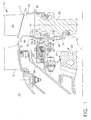
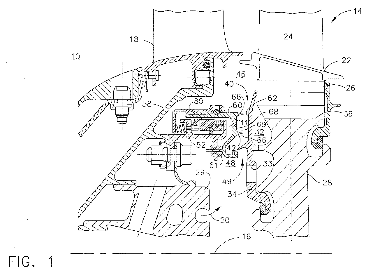
- FIG. 1 is a cross-sectional view illustration of a portion of an exemplary gas
turbine engine high pressure turbine and a first exemplary embodiment of an
aspirating gas bearing face seal with axially extending teeth.
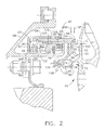
- FIG. 2 is an enlarged cross-sectional view illustration of the gas bearing face
seal illustrated in FIG. 1.
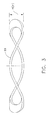
- FIG. 3 is a perspective view illustration of a wave spring alternative biasing
means.
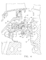
- FIG. 4 is a cross-sectional view illustration of a portion of an exemplary gas
turbine engine high pressure turbine and a second exemplary embodiment of
a gas bearing face seal with rotatable axially extending teeth.
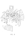
- FIG. 5 is a perspective view illustration of a double wrap wave spring
alternative biasing means.
- FIG. 6 is a cross-sectional view illustration of a portion of the exemplary gas
turbine engine high pressure turbine having the double wrap wave spring
illustrated in FIG. 5.
-
-
Illustrated in FIG. 1 is a portion of a gas turbine engine including a combustor
10 and a high pressure turbine 14 circumscribed around an engine centerline
16. The high pressure turbine 14 includes a static turbine nozzle 18 and a
rotatable turbine stage 22 having coolable turbine blades 24 mounted on a
rim 26 of a rotor disk 28 of the turbine stage 22. A portion of high pressure
compressor discharge air 20 not burned in a combustor of the engine is
directed from a relatively stationary inducer 29 to air cooling passages 32 in
the rotatable rotor disk 28 for cooling blades 24. The cooling passages 32
are axially and circumferentially bounded by a side plate 34 which also helps
retain the blades 24 in slots 36 in the rim 26 of the rotor disk 28. Compressor
discharge air 20 is directed by the inducer 29 across a high pressure region
48 through apertures 33 in the side plate 34 to the air cooling passages 32.
An aspirating face seal 40 is used to restrict leakage of the high pressure
compressor discharge air 20 from the relatively high pressure region 48 to a
relatively low pressure region 46 at the juncture 49 between an rotatable
engine member exemplified by the rotor disk 28 and a stationary engine
member exemplified by a stationary structure 58. The stationary structure 58
depends from the turbine nozzle 18 and supports the inducer 29. The face
seal 40 includes a leakage path 45 between rotatable and non-rotatable
engine members and between a rotatable and non-rotatable members of the
seal. Non-rotatable is defined as not rotating with the rotor disk 28 or other
parts of an engine rotor during engine operation.
-
Illustrated in FIG. 1 and more particularly in FIG. 2 is a first exemplary
embodiment of the face seal 40 of the present invention having non-rotatable
annular radially inner and outer axially extending tooth rings 42 and 44,
respectively. The face seal 40 is designed to restrict leakage of the high
pressure compressor discharge air 20 through the leakage path 45 from the
relatively high pressure region 48 to the relatively low pressure region 46 at
the juncture 49 between the rotatable turbine stage 22 and the stationary
structure 58. A face seal ring 60 is mounted on a non-rotatable axially
translatable cylindrical piston 88 which is circumferentially continuous and
axially movably supported on a stationary face seal support structure 52. The
face seal ring 60 exemplifies an axially movable non-rotatable engine
member 61 of the present invention. The face seal support structure 52 is
fixed with respect to the stationary structure 58. The radially inner and outer
axially extending tooth rings 42 and 44 are mounted on the face seal ring 60
and extend radially outward from an axially facing generally planar non-rotatable
gas bearing face surface 68 towards an axially facing generally
planar rotatable substantially planar gas bearing face surface 62. The face
seal ring 60 is supported for axial movement with respect to the rotatable gas
bearing face surface 62 which is on the side plate 34 that is mounted to the
rotor disk 28. The radially inner and outer tooth rings 42 and 44 provide for
low heat input into the rotatable component which is exemplified herein as the
side plate 34 and the rotor disk 28 to which it is mounted. The radially inner
and outer tooth rings 42 and 44 help maintain a smooth rotor surface finish
which is exemplified herein as the rotatable gas bearing face surface 62.
-
An annular plenum 69 is bounded by the inner and outer tooth rings 42 and
44 and the non-rotatable gas bearing face surface 68 radially extending
between the inner and outer tooth rings 42 and 44. The inner and outer tooth
rings 42 and 44 extend axially towards the rotatable gas bearing face surface
62 on the side plate 34 and have pointed ends 66 proximate to the rotatable
gas bearing face surface 62. A plurality of circumferentially spaced apart vent
passages 96 through the face seal ring 60 provide pressure communication
between the plenum 69 and low pressure region 46. The vent passages 96
pressurize the plenum 69 with high pressure air from the high pressure region
48 therein during engine operation when there is a substantial pressure
differential between high and low pressure regions 48 and 46. An axial gap G
is defined between the non-rotatable gas bearing face surface 68 and the
rotatable gas bearing face surface 62.
-
An annular auxiliary seal 73 is also used to restrict airflow across the leakage
path 45 and to create sufficient pressure, when the engine is operating, to
urge the face seal ring 60 towards the rotatable gas bearing face surface 62.
The auxiliary seal 73 includes an annular restrictor tooth 74 extending radially
across the leakage path 45 towards an annular seal land 80 having an
annular auxiliary seal surface 78. A radial gap H is defined between the
annular restrictor tooth 74 and the auxiliary seal surface 78. The restrictor
tooth 74 is radially spaced apart from and proximate the annular seal land 80.
The annular restrictor tooth 74 and annular seal land 80 are circumscribed
around the engine centerline 16. In the exemplary embodiment of the
invention illustrated in FIG. 1, the restrictor tooth 74 is attached to the
rotatable side plate 34 and the seal land 80 having the auxiliary seal surface
78 is attached to the face seal ring 60.
-
A pull off biasing means 82 is used for urging the inner and outer tooth rings
42 and 44 axially away from the rotatable gas bearing face surface 62 on the
side plate 34 when the engine is not running and/or when the pressures in the
high and low pressure regions 48 and 46 are substantially equal. The biasing
means 82 illustrated in FIG. 1 is a plurality of circumferentially spaced apart
coil springs 84 disposed within circumferentially spaced apart spring
chambers 85 formed in part by radially extending static and axially movable
flanges 86 and 87 attached to the face seal support structure 52 and the
translatable cylindrical piston 88 respectively. Circumferentially spaced apart
guide and support pins 130 extend aftwardly from the face seal ring 60
through bushings 132 disposed in pin receiving holes 134 extending through
guide and support pin flanges 138 mounted on the face seal support structure
52 forming a guide and support assembly. The guide and support assembly
helps to radially support and axially guide the face seal ring 60.
-
An alternative biasing means 82, illustrated in FIG. 3, is a wave spring 89,
also known as a wave spring or a cockle spring which would be disposed in a
continuous annular spring chamber 94 (illustrated in FIG. 6) formed in part by
the static and axially movable flanges 86 and 87 described above and
illustrated in FIG. 1. The wave spring 89 may be a single wrap wave spring
as illustrated in FIG. 3 or a multiple wrap wave spring as illustrated by a
double wrap wave spring 91 illustrated in FIGS. 5 and 6.
-
Another alternative biasing means 82, one known to those skilled in the art, is
a plurality of circumferentially spaced apart coil springs disposed on the
circumferentially spaced apart pins usually mounted on the face seal support
structure 52. Because the spring 84 used for urging the inner and outer tooth
rings 42 and 44 away from the rotatable gas bearing face surface 62, it is also
referred to as a pull off spring.
-
The face seal ring 60 is designed to translate between axial retracted and
sealing positions RP and SP respectively as measured at the non-rotatable
gas bearing face surface 68, denoted by arrows marked accordingly, as a
result of forces acting on the face seal ring 60. The face seal ring 60 is
illustrated in its sealing position in FIG. 4. The forces are the result of
pressures in the relatively low and high pressure regions 46 and 48 acting on
surfaces and spring forces of the biasing or biasing means 82. When the
engine is running and the face seal ring 60 is in the sealing position SP and
there is an operational clearance C between the pointed ends 66 of the inner
and outer tooth rings 42 and 44 and the rotatable gas bearing face surface
62. In one exemplary embodiment of the invention, when the face seal ring
60 in the sealing position SP, the axial gap G is about 25-50 mils (.025-.050
inches), the radial gap H is about 75-150 mils (.075-.150 inches), and the
operational clearance C is about 1-8 mils (.001-.008 inches). In such an
exemplary embodiment a radius midway between the inner and outer tooth
rings 42 and 44 to the engine centerline 16 may be about 10 inches.
-
The face seals of the present invention avoid significant amounts of heating
and scratching of the rotor surfaces when seal rubs occur. Thus, reducing
heat input into the rotating components and maintaining a smooth surface
finish of the rotating seal surface. This reduces the possibility of material
degradation and premature component crack initiation. A coating could be
applied to the inner and outer tooth rings 42 and 44, also referred to as rotor
axial seal teeth, to further minimize heat input into the rotor part, exemplified
herein as the side plate 34 and the rotor disk 28 to which it is mounted.
Another coating could be applied to the static part to minims heat generation
and protect the parent material of the static part from scratches.
-
During low or no power conditions the face seal ring 60 and the inner and
outer tooth rings 42 and 44 are biased away from the rotatable gas bearing
face surface 62 by the biasing means 82. During higher power operation, the
restrictor tooth 74 restricts the discharge air 20 flowing from the relatively high
pressure region 48 to the relatively low pressure region 46 thereby causing a
pressure differential between high and low pressure regions 48 and 46. The
pressure differential between high and low pressure regions 48 and 46 acts
on the face seal ring 60 and urges the face seal ring 60 and the inner and
outer tooth rings 42 and 44 and tooth toward the rotatable gas bearing face
surface 62.
-
A portion of the high pressure discharge air 20 is supplied to a gas bearing
space 100, which includes the annular plenum 69, between the face seal ring
60 and the rotatable gas bearing face surface 62 through the vent passages
96 in the face sealing ring to establish a predetermined gas bearing face
clearance. Pressure forces developed in the gas bearing space 100 oppose
further motion of the face seal ring 60 and the inner and outer tooth rings 42
and 44 toward the rotatable gas bearing face surface 62. Accelerations and
other motion of the face seal ring 60 and the inner and outer tooth rings 42
and 44 towards the rotatable gas bearing face surface 62 increases the
pressure forces in the gas bearing space 100, thereby urging the face seal
ring away from the rotatable gas bearing face surface to maintain the
predetermined clearance.
-
As the engine is started, the compressor discharge pressure rises and the
pressure in the high pressure region 48 begins to rise because the restrictor
tooth 74 restricts the discharge air 20 flowing from the relatively high pressure
region 48 to the relatively low pressure region 46. The pressure differential
between the low and high pressure regions 46 and 48 results in a closing
pressure force acting on face seal ring 60. The pressure force acts against a
spring force from the biasing means 82 to urge face seal ring 60 and the inner
and outer tooth rings 42 and 44 toward the rotatable gas bearing face surface
62.
-
As face seal ring 60 reaches the sealing position SP, the axial gap G
becomes much smaller than the radial gap H, the pressure drop across the
restrictor tooth 74 is insubstantial and airflow caused by the pressure drop
between the low and high pressure regions 46 and 48 occurs substantially
across gap between the face seal ring 60 and the inner and outer tooth rings
42 and 44 and the rotatable gas bearing face surface 62. Thus, gas bearing
forces are developed at the non-rotatable gas bearing face surface 68 and
the rotatable gas bearing face surface 62 which, acting with the spring force,
balance the closing force and maintain the operational clearance C between
the pointed ends 66 of the inner and outer tooth rings 42 and 44 and the
rotatable gas bearing face surface 62 at a predetermined size.
-
A secondary seal means, such as a circumferentially extending split piston
ring secondary seal 120, is provided to allow the face seal ring 60 to translate
axially in response to the motions of the rotating surface on the rotor. The
piston ring secondary seal 120 is urged radially inwardly by spring means,
such as second coil springs 76, against a radially inwardly facing annular
inner surface 118 of the face seal ring 60. A circumferentially extending
secondary seal dam 122 on the piston ring secondary seal 120 is urged into
radial sealing engagement with the inner surface 118. The piston ring
secondary seal 120 is urged axially by a third spring means, such as by a
plurality of circumferentially spaced third coil springs 124, into engagement
with an axially facing substantially planar sealing surface 126 on the face seal
support structure 52.
-
Illustrated in FIG. 3 is a second exemplary embodiment of the face seal 40 of
the present invention having axially extending annular radially inner and outer
rotatable tooth rings 142 and 144 mounted on the side plate 34 which is
attached to the rotatable turbine stage 22. The rotatable tooth rings 142 and
144 are engageable with a substantially planar non-rotatable gas bearing face
surface 168. The face seal ring 60 includes the non-rotatable gas bearing
face surface 168 and is mounted on the translatable cylindrical piston 88
which is axially movably supported on the stationary face seal support
structure 52. The inner and outer rotatable tooth rings 142 and 144 extend
axially from the rotatable gas bearing face surface 162 towards and have
teeth which are proximate the non-rotatable gas bearing face surface 168.
The face seal ring 60 containing the non-rotatable gas bearing face surface
168 is supported for axial movement with respect to the inner and outer
rotatable tooth rings 142 and 144 on the side plate 34 which is attached to the
rotor disk 28. The annular restrictor tooth 74 is attached to the face seal ring
60 and the auxiliary seal surface 78 and the seal land 80 are attached to the
rotatable side plate 34.
-
For the sake of good order, various aspects of the invention are set out in the
following clauses:-
- 1. A gas turbine engine aspirating face seal (40) comprising:
- a rotatable engine member (28) and a non-rotatable engine member
(58) and a leakage path (45) therebetween,
- an annular generally planar non-rotatable gas bearing face surface
(68) circumscribed about a centerline (16) and operably associated with said
non-rotatable engine member (58),
- an annular generally planar rotatable gas bearing face surface (62)
circumscribed about said centerline (16) and operably associated with said
rotatable engine member (28),
- radially inner and outer tooth rings (42, 44) axially extending away from
one of said gas bearing face surfaces across said leakage path (45) and
towards a second one of said gas bearing face surfaces,
- an annular plenum (69) located between said inner and outer tooth
rings (42, 44) and a portion of said gas bearing face surface (68) between
said inner and outer tooth rings,
- said inner and outer tooth rings (42, 44) having pointed ends (66)
proximate to said second one of said gas bearing face surfaces, and
a biasing means (82) for urging said inner and outer tooth rings (42, 44)
axially away from said second one of said gas bearing face surfaces.
- 2. A seal (40) as in clause 1 wherein said rotatable engine member is a
side plate (34) mounted on a rotor disk (28) and said non-rotatable engine
member (61) is mounted on a translatable cylindrical piston (88) which is
circumferentially continuous and axially movably supported on a stationary
face seal support structure (52).
- 3. A seal (40) as in clause 1 further comprising an auxiliary seal having a
restrictor tooth (74) radially spaced apart from and proximate to a seal land
(80) disposed between said rotatable engine member (28) non-rotatable
engine member (61).
- 4. A seal (40) as in clause 3 further comprising an auxiliary seal disposed
across said leakage path (45) radially inwardly of said inner and outer tooth
rings (42, 44), said auxiliary seal comprising an annular restrictor tooth (74)
radially spaced apart from and proximate to an annular seal land (80) having
an annular auxiliary seal surface (78) circumscribed around said engine
centerline (16).
- 5. A seal (40) as in clause 2 wherein said rotatable engine member is a
side plate (34) mounted on a rotor disk (28) and said non-rotatable engine
member (61) is mounted on a translatable cylindrical piston (88) which is
circumferentially continuous and axially movably supported on a stationary
face seal support structure (52).
- 6. A seal (40) as in clause 5 further comprising an auxiliary seal disposed
across said leakage path (45) radially inwardly of said inner and outer tooth
rings (42, 44), said auxiliary seal comprising an annular restrictor tooth (74)
radially spaced apart from and proximate to an annular seal land (80) having
an annular auxiliary seal surface (78) circumscribed around said engine
centerline (16).
- 7. A seal (40) as in clause 4 wherein said biasing means (82) is operably
disposed between said cylindrical piston (88) and said stationary face seal
support structure (52).
- 8. A seal (40) as in clause 7 wherein said biasing means (82) includes a
plurality of circumferentially spaced apart coil springs (84) disposed within
circumferentially spaced apart spring chambers (85) formed in part by radially
extending static and axially movable flanges (86, 87) attached to said face
seal support structure (52) and said translatable cylindrical piston (88)
respectively.
- 9. A seal (40) as in clause 7 wherein said biasing means (82) includes a
wave spring (89) disposed in a continuous annular spring chamber formed in
part by radially extending static and axially movable flanges (86, 87) attached
to said face seal support structure (52) and said translatable cylindrical piston
(88) respectively.
- 10. A seal (40) as in clause 7 further comprising an auxiliary seal having a
restrictor tooth (74) radially spaced apart from and proximate to with a seal
land (80) disposed between said rotatable engine member (28) non-rotatable
engine member (61).
- 11. A seal (40) as in clause 7 further comprising an auxiliary seal disposed
across said leakage path (45) radially inwardly of said inner and outer tooth
rings (42, 44), said auxiliary seal comprising an annular restrictor tooth (74)
radially spaced apart from and proximate to an annular seal land (80) having
an annular auxiliary seal surface (78) circumscribed around said engine
centerline (16).
- 12. A seal (40) as in clause 11 wherein said rotatable engine member is a
side plate (34) mounted on a rotor disk (28) and said non-rotatable engine
member (61) is mounted on a translatable cylindrical piston (88) which is
circumferentially continuous and axially movably supported on a stationary
face seal support structure (52).
- 13. A gas turbine engine seal assembly comprising:
- an aspirating face seal (40) disposed between a relatively high
pressure region (48) and a relatively low pressure region (46) at a juncture
(49) between a rotatable engine member (28) and a stationary engine
member (58),
- an annular generally planar non-rotatable gas bearing face surface
(68) circumscribed about a centerline (16) and operably associated with said
non-rotatable engine member (58),
- an annular generally planar rotatable gas bearing face surface (62)
circumscribed about said centerline (16) and operably associated with said
rotatable engine member (28),
- a leakage path (45) in part axially extending between said gas bearing
face surfaces (62, 68),
- radially inner and outer tooth rings (42, 44) axially extending away from
a first one of said gas bearing face surfaces (62, 68) across a portion of said
leakage path (45) and towards a second one of said gas bearing face
surfaces (62, 68),
- an annular plenum (69) located between said inner and outer tooth
rings (42, 44) and said first one of said gas bearing face surfaces (62, 68),
- said inner and outer tooth rings (42, 44) having pointed ends (66)
proximate to said second one of said gas bearing face surfaces (62, 68), and
- a biasing means (82) for urging said inner and outer tooth rings (42,
44) axially away from said second one of said gas bearing face surfaces (62,
68).
- 14. An assembly as in clause 13 further comprising an auxiliary seal
disposed across said leakage path (45) radially inwardly of said inner and
outer tooth rings (42, 44), said auxiliary seal comprising an annular restrictor
tooth (74) radially spaced apart from and proximate to an annular seal land
(80) having an annular auxiliary seal surface (78) circumscribed around said
engine centerline (16).
- 15. An assembly as in clause 13 wherein said rotatable engine member is
a side plate (34) mounted on a rotor disk (28) and said non-rotatable engine
member (61) is a face seal ring (60) mounted on a translatable cylindrical
piston (88) which is circumferentially continuous and axially movably
supported on a stationary face seal support structure (52).
- 16. An assembly as in clause 15 further comprising an auxiliary seal
disposed across said leakage path (45) radially inwardly of said inner and
outer tooth rings (42, 44), said auxiliary seal comprising an annular restrictor
tooth (74) radially spaced apart from and proximate to an annular seal land
(80) having an annular auxiliary seal surface (78) circumscribed around said
engine centerline (16).
- 17. An assembly as in clause 16 wherein said annular restrictor tooth (74)
is attached to said side plate (34) and said annular seal land (80) is attached
to said face seal ring (60).
- 18. An assembly as in clause 17 wherein said biasing means (82) operably
disposed between said cylindrical piston (88) and said stationary face seal
support structure (52).
- 19. An assembly as in clause 18 wherein said biasing means (82) includes
a plurality of circumferentially spaced apart coil springs (84) disposed within
circumferentially spaced apart spring chambers (85) formed in part by radially
extending static and axially movable flanges (86, 87) attached to said face
seal support structure (52) and said translatable cylindrical piston (88)
respectively.
- 20. An assembly as in clause 18 wherein said biasing means (82) includes
a wave spring (89) disposed in a continuous annular spring chamber formed
in part by radially extending static and axially movable flanges (86, 87)
attached to said face seal support structure (52) and said translatable
cylindrical piston (88) respectively.
- 21. An assembly as in clause 18 wherein said said face seal ring (60) has
said radially inner and outer tooth rings (42, 44) extending axially away from
said non-rotatable gas bearing face surface (68).
- 22. A gas turbine engine seal assembly comprising:
- an aspirating face seal (40) disposed between a relatively high
pressure region (48) and a relatively low pressure region (46) at a juncture
(49) between a rotatable engine member (28) and a stationary engine
member (58),
- said stationary structure (58) depending from a turbine nozzle (18) and
supporting an inducer (29) which is operable to direct a portion of high
pressure compressor discharge air (20) across said high pressure region (48),
- an annular generally planar non-rotatable gas bearing face surface
(68) circumscribed about a centerline (16) and operably associated with said
non-rotatable engine member (58),
- an annular generally planar rotatable gas bearing face surface (62)
circumscribed about said centerline (16) and operably associated with said
rotatable engine member (28),
- a leakage path (45) in part axially extending between said gas bearing
face surfaces (62,68),
- radially inner and outer tooth rings (42, 44) axially extending away from
a first one of said gas bearing face surfaces (62, 68) across a portion of said
leakage path (45) and towards a second one of said gas bearing face
surfaces (62, 68),
- an annular plenum (69) located between said inner and outer tooth
rings (42, 44) and said first one of said gas bearing face surfaces (62, 68),
- said inner and outer tooth rings (42, 44) having pointed ends (66)
proximate to said second one of said gas bearing face surfaces (62, 68), and
- a biasing means (82) for urging said inner and outer tooth rings (42,
44) axially away from said second one of said gas bearing face surfaces (62,
68).
- 23. An assembly as in clause 22 wherein said rotatable engine member
(28) is a side plate (34) mounted on a rotor disk (28) and said non-rotatable
engine member (61) is a face seal ring (60) mounted on a translatable
cylindrical piston (88) which is circumferentially continuous and axially
movably supported on a stationary face seal support structure (52).
- 24. An assembly as in clause 23 further comprising an auxiliary seal
disposed across said leakage path (45) radially inwardly of said inner and
outer tooth rings (42, 44), said auxiliary seal comprising an annular restrictor
tooth (74) radially spaced apart from and proximate to an annular seal land
(80) having an annular auxiliary seal surface (78) circumscribed around said
engine centerline (16).
- 25. An assembly as in clause 24 wherein said annular restrictor tooth (74)
is attached to said side plate (34) and said annular seal land (80) is attached
to said face seal ring (60).
- 26. An assembly as in clause 25 wherein said biasing means (82) is
operably disposed between said cylindrical piston (88) and said stationary
face seal support structure (52).
- 27. An assembly as claimed in claim 25 wherein said biasing means (82)
includes a plurality of circumferentially spaced apart coil springs (84)
disposed within circumferentially spaced apart spring chambers (85) formed
in part by radially extending static and axially movable flanges (86, 87)
attached to said face seal support structure (52) and said translatable
cylindrical piston (88) respectively.
- 28. An assembly as claimed in claim 25 wherein said biasing means (82)
includes a wave spring (89) disposed in a continuous annular spring chamber
formed in part by radially extending static and axially movable flanges (86, 87)
attached to said face seal support structure (52) and said translatable
cylindrical piston (88) respectively.
-