EP1348893A2 - Belt type continuously variable transmission - Google Patents
Belt type continuously variable transmission Download PDFInfo
- Publication number
- EP1348893A2 EP1348893A2 EP03006379A EP03006379A EP1348893A2 EP 1348893 A2 EP1348893 A2 EP 1348893A2 EP 03006379 A EP03006379 A EP 03006379A EP 03006379 A EP03006379 A EP 03006379A EP 1348893 A2 EP1348893 A2 EP 1348893A2
- Authority
- EP
- European Patent Office
- Prior art keywords
- metal
- pulley
- pulley half
- metal ring
- drive
- Prior art date
- Legal status (The legal status is an assumption and is not a legal conclusion. Google has not performed a legal analysis and makes no representation as to the accuracy of the status listed.)
- Granted
Links
Images


Classifications
-
- F—MECHANICAL ENGINEERING; LIGHTING; HEATING; WEAPONS; BLASTING
- F16—ENGINEERING ELEMENTS AND UNITS; GENERAL MEASURES FOR PRODUCING AND MAINTAINING EFFECTIVE FUNCTIONING OF MACHINES OR INSTALLATIONS; THERMAL INSULATION IN GENERAL
- F16H—GEARING
- F16H9/00—Gearings for conveying rotary motion with variable gear ratio, or for reversing rotary motion, by endless flexible members
- F16H9/02—Gearings for conveying rotary motion with variable gear ratio, or for reversing rotary motion, by endless flexible members without members having orbital motion
- F16H9/04—Gearings for conveying rotary motion with variable gear ratio, or for reversing rotary motion, by endless flexible members without members having orbital motion using belts, V-belts, or ropes
- F16H9/12—Gearings for conveying rotary motion with variable gear ratio, or for reversing rotary motion, by endless flexible members without members having orbital motion using belts, V-belts, or ropes engaging a pulley built-up out of relatively axially-adjustable parts in which the belt engages the opposite flanges of the pulley directly without interposed belt-supporting members
- F16H9/125—Gearings for conveying rotary motion with variable gear ratio, or for reversing rotary motion, by endless flexible members without members having orbital motion using belts, V-belts, or ropes engaging a pulley built-up out of relatively axially-adjustable parts in which the belt engages the opposite flanges of the pulley directly without interposed belt-supporting members characterised by means for controlling the geometrical interrelationship of pulleys and the endless flexible member, e.g. belt alignment or position of the resulting axial pulley force in the plane perpendicular to the pulley axis
-
- F—MECHANICAL ENGINEERING; LIGHTING; HEATING; WEAPONS; BLASTING
- F16—ENGINEERING ELEMENTS AND UNITS; GENERAL MEASURES FOR PRODUCING AND MAINTAINING EFFECTIVE FUNCTIONING OF MACHINES OR INSTALLATIONS; THERMAL INSULATION IN GENERAL
- F16G—BELTS, CABLES, OR ROPES, PREDOMINANTLY USED FOR DRIVING PURPOSES; CHAINS; FITTINGS PREDOMINANTLY USED THEREFOR
- F16G5/00—V-belts, i.e. belts of tapered cross-section
- F16G5/16—V-belts, i.e. belts of tapered cross-section consisting of several parts
-
- F—MECHANICAL ENGINEERING; LIGHTING; HEATING; WEAPONS; BLASTING
- F16—ENGINEERING ELEMENTS AND UNITS; GENERAL MEASURES FOR PRODUCING AND MAINTAINING EFFECTIVE FUNCTIONING OF MACHINES OR INSTALLATIONS; THERMAL INSULATION IN GENERAL
- F16H—GEARING
- F16H55/00—Elements with teeth or friction surfaces for conveying motion; Worms, pulleys or sheaves for gearing mechanisms
- F16H55/32—Friction members
- F16H55/52—Pulleys or friction discs of adjustable construction
- F16H55/56—Pulleys or friction discs of adjustable construction of which the bearing parts are relatively axially adjustable
Definitions
- the present invention relates to a belt type continuously variable transmission in which a metal belt is wound around a drive pulley and a driven pulley.
- a belt type continuously variable transmission that uses a metal belt has attracted attention as a transmission that is capable of reducing fuel consumption while simultaneously improving running performance.
- the belt type continuously variable transmission provides a relatively smooth acceleration without shift-shock, is relatively quiet in terms of running performance, and achieves lower fuel consumption compared to an automatic transmission by integral control of the transmission and an engine that maintains engine rotational speed with relatively high combustion efficiency in terms of fuel consumption.
- the saddle faces of the metal elements are made into a convex shape (i.e., crowning) to center the metal ring assembly on the saddle faces in order to prevent deterioration of durability from the edges of the metal ring assembly moving on the saddle faces of the metal elements contacting the neck parts of the metal elements and V-faces of pulleys.
- a convex shape i.e., crowning
- the metal ring assembly inevitably moves on the saddle faces under certain operating conditions of the belt type continuously variable transmission. As one of the causes, it has been found that the movement of the metal ring assembly is greatly influenced by the ratio of the flexural stiffness of the movable pulley half compared to that of the fixed pulley half of the drive pulley.
- a belt type continuously variable transmission that includes a drive pulley having a fixed pulley half and a movable pulley half; a driven pulley having a fixed pulley half and a movable pulley half; and a metal belt.
- the metal belt includes a metal ring assembly having a plurality of endless metal rings laminated onto one another; and a plurality of metal elements supported on the metal ring assembly.
- the metal belt is wound around the drive and driven pulleys.
- the movable pulley half of the drive pulley has a flexural stiffness higher than a flexural stiffness of the fixed pulley half of the drive pulley.
- the flexural stiffness of the movable pulley half of the drive pulley is set to be higher than the flexural stiffness of the fixed pulley half of the drive pulley. Therefore, it is difficult for the edges of the metal ring assembly to contact the metal elements and V-faces of the pulleys, thereby improving the durability of the metal ring assembly.
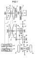
- Fig. 1 is a schematic diagram of a power transmission system of a vehicle equipped with a metal belt type continuously variable transmission according to the present invention
- Fig. 2 is a partial perspective view of a metal belt
- Fig. 3 is a front view of a metal element
- Fig. 4 is a schematic diagram used to explain the definition of misalignment
- Fig. 5 is a graph illustrating the relationship between the ratio of the metal belt type continuously variable transmission and misalignment
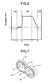
- Fig. 6 is a graph illustrating the distribution of misalignment in the peripheral direction of a metal ring assembly when pulleys are assumed to be rigid;
- Fig. 7 is a schematic diagram used to explain the definition of each position in the peripheral direction of the metal belt
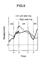
- Fig. 8 is a graph illustrating the distribution of misalignment in the peripheral direction of left and right metal ring assemblies
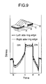
- Fig. 9 is a diagram showing the distribution of stress in the peripheral direction of the outer edges of the left and right metal ring assemblies
- Figs. 10A and 10B are schematic diagrams used to explain a model in which the flexural stiffness of the pulleys is taken into consideration;
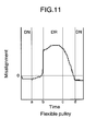
- Fig. 11 is a graph illustrating the distribution of misalignment in the peripheral direction of the metal ring assemblies when the flexural stiffness of the pulleys is taken into consideration;
- Fig. 12 is a graph illustrating the definitions of cases (1) to (9) in which the fixed pulley half and the movable pulley half have different stiffness values;
- Fig. 13 is a graph illustrating the stress on four edges of the metal ring assemblies in cases (1) to (4);
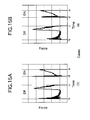
- Figs. 14A and 14B are graphs illustrating the distribution of stress in the peripheral direction of the metal ring assemblies in cases (1) and (4);
- Figs. 15A and 15B are graphs illustrating the distribution of load in the peripheral direction of the metal ring assemblies in cases (1) and (4);
- Fig. 16 is a graph illustrating the stress on the four edges of the metal ring assemblies of cases (5), (3), and (6);
- Fig. 17 is a graph illustrating the distribution of clearance and misalignment in the peripheral direction of the metal ring assemblies in case (5);
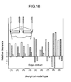
- Fig. 18 is a graph illustrating the clearance of the four edges of the metal ring assemblies in cases (1) to (9).
- the forward and backward directions, the left and right directions, and the radial direction of the metal elements used in the present invention are defined as shown in Fig. 2.
- the radial direction is defined as the radial direction of a pulley with which the metal element is in contact.
- the side closer to the rotational axis of the pulley is the radially inner side and the side further from the rotational axis of the pulley is the radially outer side.
- the left and right directions of the metal element are defined as the directions along the rotational axis of the pulley with which the metal element is in contact.
- the forward and backward directions are defined as the directions along the traveling direction of the metal element when the vehicle travels forward.
- FIG. 1 shows the schematic structure of a metal belt type continuously variable transmission T installed in an automobile.
- An input shaft 3 is connected to a crankshaft 1 of an engine E via a damper 2.
- the input shaft is also connected to a drive shaft 5 of the metal belt type continuously variable transmission T via a starting clutch 4.
- a drive pulley 6 provided on the drive shaft 5 includes a fixed pulley half 7 secured to the drive shaft 5 and a movable pulley half 8 that can move toward and away from the fixed pulley half 7.
- the movable pulley half 8 is biased toward the fixed pulley half 7 by a hydraulic pressure acting on an oil chamber 9.
- a driven pulley 11 is provided on a driven shaft 10 disposed in parallel to the drive shaft 5, and includes a fixed pulley half 12 secured to the driven shaft 10 and a movable pulley half 13 movable toward and away from the fixed pulley half 12.
- the movable pulley half 13 is biased toward the fixed pulley half 12 by a hydraulic pressure acting on an oil chamber 14.
- Wound around the drive pulley 6 and the driven pulley 11 is a metal belt 15 that includes a pair of left and right metal ring assemblies 31 and a large number of metal elements 32 supported on the metal ring assemblies 31 (see Fig. 2).
- Each of the metal ring assemblies 31 is formed by laminating twelve metal rings 33 on one another.
- a forward drive gear 16 and a reverse drive gear 17 which can be selectively connected to the driven shaft 10 via a selector 18.
- a forward driven gear 20 and a reverse driven gear 22 Secured to an output shaft 19 disposed in parallel to the driven shaft 10 are a forward driven gear 20 and a reverse driven gear 22.
- the forward driven gear 20 meshes with the forward drive gear 16.
- the reverse driven gear 22 meshes with the drive gear 17 via a reverse idle gear 21.
- Rotation of the output shaft 19 is input via a final drive gear 23 and a final driven gear 24 into a differential 25 and transmitted therefrom to driven wheels W via left and right axles 26.
- the driving force of the engine E is transmitted to the driven shaft 10 via the crankshaft 1, damper 2, input shaft 3, starting clutch 4, drive shaft 5, drive pulley 6, metal belt 15, and driven pulley 11.
- a forward range is selected, the driving force of the driven shaft 10 is transmitted to the output shaft 19 via the forward drive gear 16 and the forward driven gear 20, thereby driving the vehicle forward.
- a reverse range is selected, the driving force of the driven shaft 10 is transmitted to the output shaft 19 via the reverse drive gear 17, reverse idle gear 21, and reverse driven gear 22, thereby driving the vehicle in reverse.
- the gear ratio of the metal belt type continuously variable transmission T is continuously or steplessly adjustable by controlling the hydraulic pressures acting on the oil chamber 9 of the drive pulley 6 and the oil chamber 14 of the driven pulley 11 by a hydraulic pressure control unit U2 operated by commands from an electronic control unit U1. That is, increasing the hydraulic pressure acting on the oil chamber 14 of the driven pulley 11 relative to the hydraulic pressure acting on the oil chamber 9 of the drive pulley 6 decreases the channel width of the driven pulley 11 so as to increase the effective radius thereof while simultaneously increasing the channel width of the drive pulley 6 so as to decrease the effective radius thereof. As a result, the gear ratio of the metal belt type continuously variable transmission T therefore continuously varies toward LOW.
- the metal element 32 formed by punching out a metal sheet includes a substantially trapezoidal element main body 34, a neck portion 36 positioned between a pair of left and right ring slots 35 into which the metal ring assemblies 31 are fitted, and a substantially triangular ear portion 37 connected to an upper part of the element main body 34 via the neck portion 36.
- a pair of pulley abutment surfaces 39 Formed on opposite ends in the left and right direction of the element main body 34 are a pair of pulley abutment surfaces 39 that can abut V-faces of the drive pulley 6 and driven pulley 11.
- Main surfaces 40 are formed on the forward side and rear side in the traveling direction of the metal elements 32. The main surfaces 40 abut the main surfaces 40 of adjacent metal elements 32.
- An inclined surface 42 is formed in a lower part of the main surface 40 on the forward side in the traveling direction via a rocking edge 41 extending in the left and right direction. Furthermore, in order to join metal elements 32 that are adjacent to each other in the traveling direction, projections 43f and recesses 43r are formed on the front and rear surfaces of the ear portions 37 so that the projection 43f and the recess 43r mate with each other. Formed on lower edges of the left and right ring slots 35 are saddle faces 44 to support the inner peripheral surfaces of the metal ring assemblies 31.
- the fixed pulley half 7 of the drive pulley 6 and the fixed pulley half 12 of the driven pulley 11 are disposed in diagonal positions
- the movable pulley half 8 of the drive pulley 6 and the movable pulley half 13 of the driven pulley 11 are disposed in diagonal positions.
- the behavior of the metal belt 15 during operation of the metal belt type continuously variable transmission T has been analyzed by a simulation. Because the purpose thereof was to understand the influence of the flexural stiffness of the pulleys, the analysis was carried out using a simple model in which the number of metal elements 32 was 280 and the number of metal rings 33 of the metal ring assembly 31 was three.
- Fig. 6 shows the relationship between the misalignment (ordinate) of the metal elements 32.
- the peripheral positions (abscissa) of the metal belt 15; a , b , c , and d on the abscissa, as shown in Fig. 7, correspond to the exit portion of the driven pulley 11, the entrance portion of the drive pulley 6, the exit portion of drive pulley 6, and the entrance portion of the driven pulley 11, respectively.
- the misalignment of the metal elements 32 is maintained at a constant value in the section between b and c where the metal belt 15 is wound around the drive pulley 6 and in the section between d and a where the metal belt 15 is wound around the driven pulley 11.
- the misalignment of the metal elements 32 rapidly increases in the part b where the metal belt 15 starts to become wound around the drive pulley 6.
- the misalignment is measured relative to the center line Lb of the V-shaped channel between the fixed pulley half 12 and the movable pulley half 13 of the driven pulley 11 (see Fig. 4).
- Fig. 8 unlike the misalignment of the metal elements 32, the misalignment of the left and right metal ring assemblies 31 changes smoothly in the peripheral direction while the metal ring assemblies 31 have a difference in speed relative to the saddle faces 44 of the metal elements 32.
- Fig. 9 shows the stress on the outer edges of the left and right metal ring assemblies 31 (position A and position D). It is clear that the left and right metal ring assemblies 31 are in different states of stress due to the influence of the misalignment of the metal elements 32, and the stress is higher at the outer edges of the left and right metal ring assemblies 31.
- rotational springs representing the flexural stiffness of the drive pulley 6 were added to the simulation model, as shown in Fig. 10B.
- the flexural stiffness of the fixed pulley half 7 was set at Ks
- the flexural stiffness of the movable pulley half 8 was set at Km.
- the values for the flexural stiffness Ks and Km were calculated by creating a 3D FEM model of the pulley and adding the load of the metal belt 15 in a static manner.
- the pulley deforms in both the radial direction and the peripheral direction according to the stiffness thereof. Since the flexural deformation is the largest among the deformations, only the flexural deformation of the pulley was taken into consideration in this calculation.
- Fig. 11 shows the relationship between the misalignment of the metal elements 32 and the position of the metal belt 15 when the influence of flexing of the pulley is taken into consideration
- a , b , c , and d in the abscissa denote the peripheral positions of the metal belt 15 shown in Fig. 7.
- the stiffness of the drive pulley 6, which has a large amount of flexing is taken into consideration, and different values are set for the flexural stiffness of the left and right pulley halves 7, 8.
- the misalignment increases in the section from b to c where the metal belt 15 is wound around the drive pulley 6.
- Fig. 12 shows, for cases (1) to (9), nine combinations of the stiffness of the two pulley halves 7, 8 used in a parameter study. That is, the abscissa denotes the stiffness Ks of the pulley shaft (that is, the fixed pulley half 7) and the ordinate denotes the stiffness Km of the movable pulley half 8.
- the solid line passing through case (7) and case (9) denotes a relationship where the fixed pulley half 7 and the movable pulley half 8 have a stiffness ratio of one; in cases (1) to (4), (6), and (8) the stiffness of the movable pulley half 8 is thus greater than the stiffness of the fixed pulley half 7, and on the other hand in case (5) the stiffness of the movable pulley half 8 is less than the stiffness of the fixed pulley half 7.
- Fig. 13 shows the stress at four edges A, B, C, and D of the pair of metal ring assemblies 31 for the four cases (1), (2), (3), and (4) where the absolute value of the stiffness is changed while maintaining a substantially constant stiffness ratio of the fixed pulley half 7 and the movable pulley half 8 (see broken line in Fig. 12).
- the stress value used is the maximum value in the peripheral direction of the metal ring assemblies 31.
- Fig. 14 shows the distribution of stress in the peripheral direction of the metal ring assembly 31 in cases (1) and (4).
- case (1) where the stiffness is higher than in case (4), it was found that the stress amplitude at the entrance of the drive pulley 6 increased. It is conceivable that the reason therefor is because in case (1), where the flexural stiffness of the drive pulley 6 is high, the impact load of the V-face of the drive pulley 6 acting on the pulley abutment surfaces 39 of the metal elements 32 increases (see the entrance position b of the drive pulley 6 in FIG. 15 (A)), thereby promoting the increase in stress of the metal ring assembly 31.
- Fig. 16 shows the stress on the four edges A, B, C, and D of the metal ring assemblies 31 for the cases (5), (3), and (6) where the stiffness ratio (Ks/Km) of the fixed pulley half 7 and the movable pulley half 8 is changed. It was found that, although there were slight differences in the stress on the four edges A, B, C, and D of the metal ring assemblies 31 for cases (5), (3), and (6), the influence of the stiffness ratio was low. However, the stiffness ratio had a direct effect on the relative alignment between the metal elements 32 and the metal ring assemblies 31.
- Fig. 17 shows the clearance ⁇ (see Fig. 3) between the metal ring assembly 31 on the movable pulley half 8 side and the neck portion 36 of the metal elements 32, the misalignment of the metal elements 32, and the misalignment of this metal ring assembly 31.
- the clearance ⁇ between the metal ring assembly 31 on the movable pulley half 8 side and the neck portion 36 of the metal elements 32 is extremely small in the region from b to c where the metal belt 15 is wound around the drive pulley 6. Therefore, there is a possibility that the inner edge of the metal ring assembly 31 comes into contact with the metal elements 32, thereby degrading the durability.
- Fig. 18 shows the clearance at the outer edges and the clearance at the inner edges of the left and right metal ring assemblies 31 for all the cases (1) to (9).
- a negative value for the clearance suggests that the edge of the metal ring assembly 31 is in contact with the metal element 32 or the driven pulley 6.
- a belt type continuously variable transmission includes a drive pulley having a fixed pulley half and a movable pulley half; a driven pulley having a fixed pulley half and a movable pulley half; and a metal belt.
- the metal belt includes a metal ring assembly having a plurality of endless metal rings laminated on one another and a plurality of metal elements supported on the metal ring assembly. The metal belt is wound around the drive pulley and the driven pulley.
- the movable pulley half of the drive pulley has a flexural stiffness higher than that of the fixed pulley half of the drive pulley, wherein it is difficult for the edges of the metal ring assembly to contact the metal elements and a V-face of the drive pulley.
Abstract
Description
- The present invention relates to a belt type continuously variable transmission in which a metal belt is wound around a drive pulley and a driven pulley.
- In recent years, under circumstances of increasing demand for environmentally friendly automobiles, a belt type continuously variable transmission that uses a metal belt has attracted attention as a transmission that is capable of reducing fuel consumption while simultaneously improving running performance. The belt type continuously variable transmission provides a relatively smooth acceleration without shift-shock, is relatively quiet in terms of running performance, and achieves lower fuel consumption compared to an automatic transmission by integral control of the transmission and an engine that maintains engine rotational speed with relatively high combustion efficiency in terms of fuel consumption. There is an increasing need for additional increased torque transmission capacity of the belt type continuously variable transmission to enhance multi-purpose features that enable application to various types of vehicles.
- Conventionally, as disclosed in Japanese Patent Application Laid-open No. 52-47158, the saddle faces of the metal elements are made into a convex shape (i.e., crowning) to center the metal ring assembly on the saddle faces in order to prevent deterioration of durability from the edges of the metal ring assembly moving on the saddle faces of the metal elements contacting the neck parts of the metal elements and V-faces of pulleys.
- However, even if the saddle faces of the metal elements are configured to have a convex shape so as to perform the centering function, the metal ring assembly inevitably moves on the saddle faces under certain operating conditions of the belt type continuously variable transmission. As one of the causes, it has been found that the movement of the metal ring assembly is greatly influenced by the ratio of the flexural stiffness of the movable pulley half compared to that of the fixed pulley half of the drive pulley.
- It is an object of the present invention to overcome the above-described deficiencies of the related art.
- It is also an object of the present invention to improve the durability of a metal ring assembly of a belt type continuously variable transmission by making it difficult for the edges of the metal ring assembly to contact the metal elements and V-faces of the drive and driven pulleys.
- In order to achieve the above objects, in accordance with the present invention, there is provided a belt type continuously variable transmission that includes a drive pulley having a fixed pulley half and a movable pulley half; a driven pulley having a fixed pulley half and a movable pulley half; and a metal belt. The metal belt includes a metal ring assembly having a plurality of endless metal rings laminated onto one another; and a plurality of metal elements supported on the metal ring assembly. The metal belt is wound around the drive and driven pulleys. The movable pulley half of the drive pulley has a flexural stiffness higher than a flexural stiffness of the fixed pulley half of the drive pulley.
- In the above-described structural arrangement, the flexural stiffness of the movable pulley half of the drive pulley is set to be higher than the flexural stiffness of the fixed pulley half of the drive pulley. Therefore, it is difficult for the edges of the metal ring assembly to contact the metal elements and V-faces of the pulleys, thereby improving the durability of the metal ring assembly.
- A mode for carrying out the present invention is explained below by reference to an embodiment of the present invention shown in the attached drawings.
- Fig. 1 is a schematic diagram of a power transmission system of a vehicle equipped with a metal belt type continuously variable transmission according to the present invention;
- Fig. 2 is a partial perspective view of a metal belt;
- Fig. 3 is a front view of a metal element;
- Fig. 4 is a schematic diagram used to explain the definition of misalignment;
- Fig. 5 is a graph illustrating the relationship between the ratio of the metal belt type continuously variable transmission and misalignment;
- Fig. 6 is a graph illustrating the distribution of misalignment in the peripheral direction of a metal ring assembly when pulleys are assumed to be rigid;
- Fig. 7 is a schematic diagram used to explain the definition of each position in the peripheral direction of the metal belt;
- Fig. 8 is a graph illustrating the distribution of misalignment in the peripheral direction of left and right metal ring assemblies;
- Fig. 9 is a diagram showing the distribution of stress in the peripheral direction of the outer edges of the left and right metal ring assemblies;
- Figs. 10A and 10B are schematic diagrams used to explain a model in which the flexural stiffness of the pulleys is taken into consideration;
- Fig. 11 is a graph illustrating the distribution of misalignment in the peripheral direction of the metal ring assemblies when the flexural stiffness of the pulleys is taken into consideration;
- Fig. 12 is a graph illustrating the definitions of cases (1) to (9) in which the fixed pulley half and the movable pulley half have different stiffness values;
- Fig. 13 is a graph illustrating the stress on four edges of the metal ring assemblies in cases (1) to (4);
- Figs. 14A and 14B are graphs illustrating the distribution of stress in the peripheral direction of the metal ring assemblies in cases (1) and (4);
- Figs. 15A and 15B are graphs illustrating the distribution of load in the peripheral direction of the metal ring assemblies in cases (1) and (4);
- Fig. 16 is a graph illustrating the stress on the four edges of the metal ring assemblies of cases (5), (3), and (6);
- Fig. 17 is a graph illustrating the distribution of clearance and misalignment in the peripheral direction of the metal ring assemblies in case (5); and
- Fig. 18 is a graph illustrating the clearance of the four edges of the metal ring assemblies in cases (1) to (9).
- For purposes of explaining the present invention, the forward and backward directions, the left and right directions, and the radial direction of the metal elements used in the present invention are defined as shown in Fig. 2. The radial direction is defined as the radial direction of a pulley with which the metal element is in contact. The side closer to the rotational axis of the pulley is the radially inner side and the side further from the rotational axis of the pulley is the radially outer side. The left and right directions of the metal element are defined as the directions along the rotational axis of the pulley with which the metal element is in contact. The forward and backward directions are defined as the directions along the traveling direction of the metal element when the vehicle travels forward.
- FIG. 1 shows the schematic structure of a metal belt type continuously variable transmission T installed in an automobile. An
input shaft 3 is connected to acrankshaft 1 of an engine E via adamper 2. The input shaft is also connected to adrive shaft 5 of the metal belt type continuously variable transmission T via a startingclutch 4. Adrive pulley 6 provided on thedrive shaft 5 includes a fixedpulley half 7 secured to thedrive shaft 5 and amovable pulley half 8 that can move toward and away from the fixedpulley half 7. Themovable pulley half 8 is biased toward the fixedpulley half 7 by a hydraulic pressure acting on anoil chamber 9. - A driven
pulley 11 is provided on a drivenshaft 10 disposed in parallel to thedrive shaft 5, and includes a fixedpulley half 12 secured to the drivenshaft 10 and amovable pulley half 13 movable toward and away from the fixedpulley half 12. Themovable pulley half 13 is biased toward the fixedpulley half 12 by a hydraulic pressure acting on anoil chamber 14. Wound around thedrive pulley 6 and the drivenpulley 11 is ametal belt 15 that includes a pair of left and rightmetal ring assemblies 31 and a large number ofmetal elements 32 supported on the metal ring assemblies 31 (see Fig. 2). Each of themetal ring assemblies 31 is formed by laminating twelvemetal rings 33 on one another. - Relatively rotatably supported on the driven
shaft 10 are aforward drive gear 16 and areverse drive gear 17 which can be selectively connected to the drivenshaft 10 via aselector 18. Secured to anoutput shaft 19 disposed in parallel to the drivenshaft 10 are a forward drivengear 20 and a reverse drivengear 22. The forward drivengear 20 meshes with theforward drive gear 16. The reverse drivengear 22 meshes with thedrive gear 17 via areverse idle gear 21. - Rotation of the
output shaft 19 is input via afinal drive gear 23 and a final drivengear 24 into a differential 25 and transmitted therefrom to driven wheels W via left andright axles 26. - The driving force of the engine E is transmitted to the driven
shaft 10 via thecrankshaft 1,damper 2,input shaft 3, startingclutch 4,drive shaft 5,drive pulley 6,metal belt 15, and drivenpulley 11. When a forward range is selected, the driving force of the drivenshaft 10 is transmitted to theoutput shaft 19 via theforward drive gear 16 and the forward drivengear 20, thereby driving the vehicle forward. When a reverse range is selected, the driving force of the drivenshaft 10 is transmitted to theoutput shaft 19 via thereverse drive gear 17,reverse idle gear 21, and reverse drivengear 22, thereby driving the vehicle in reverse. - At this time, the gear ratio of the metal belt type continuously variable transmission T is continuously or steplessly adjustable by controlling the hydraulic pressures acting on the
oil chamber 9 of thedrive pulley 6 and theoil chamber 14 of the drivenpulley 11 by a hydraulic pressure control unit U2 operated by commands from an electronic control unit U1. That is, increasing the hydraulic pressure acting on theoil chamber 14 of the drivenpulley 11 relative to the hydraulic pressure acting on theoil chamber 9 of thedrive pulley 6 decreases the channel width of the drivenpulley 11 so as to increase the effective radius thereof while simultaneously increasing the channel width of thedrive pulley 6 so as to decrease the effective radius thereof. As a result, the gear ratio of the metal belt type continuously variable transmission T therefore continuously varies toward LOW. On the other hand, increasing the hydraulic pressure acting on theoil chamber 9 of thedrive pulley 6 relative to the hydraulic pressure acting on theoil chamber 14 of the drivenpulley 11 decreases the channel width of thedrive pulley 6 so as to increase the effective radius thereof while simultaneously increasing the channel width of the drivenpulley 11 so as to decrease the effective radius thereof. As a result, the gear ratio of the metal belt type continuously variable transmission T continuously varies toward OD. - As shown in Figs. 2 and 3, the
metal element 32 formed by punching out a metal sheet includes a substantially trapezoidal elementmain body 34, aneck portion 36 positioned between a pair of left andright ring slots 35 into which themetal ring assemblies 31 are fitted, and a substantiallytriangular ear portion 37 connected to an upper part of the elementmain body 34 via theneck portion 36. Formed on opposite ends in the left and right direction of the elementmain body 34 are a pair of pulley abutment surfaces 39 that can abut V-faces of thedrive pulley 6 and drivenpulley 11. Main surfaces 40 are formed on the forward side and rear side in the traveling direction of themetal elements 32. Themain surfaces 40 abut themain surfaces 40 ofadjacent metal elements 32. Aninclined surface 42 is formed in a lower part of themain surface 40 on the forward side in the traveling direction via a rockingedge 41 extending in the left and right direction. Furthermore, in order to joinmetal elements 32 that are adjacent to each other in the traveling direction,projections 43f andrecesses 43r are formed on the front and rear surfaces of theear portions 37 so that theprojection 43f and therecess 43r mate with each other. Formed on lower edges of the left andright ring slots 35 are saddle faces 44 to support the inner peripheral surfaces of themetal ring assemblies 31. - As shown in Fig. 4, in the metal belt type continuously variable transmission T formed by winding the
metal belt 15 around thedrive pulley 6 and the drivenpulley 11, the fixedpulley half 7 of thedrive pulley 6 and the fixedpulley half 12 of the drivenpulley 11 are disposed in diagonal positions, and themovable pulley half 8 of thedrive pulley 6 and themovable pulley half 13 of the drivenpulley 11 are disposed in diagonal positions. Therefore, when the movable pulley halves 8, 13 of thedrive pulley 6 and the drivenpulley 11 move toward or away from the fixed pulley halves 7, 12, a central line La of the V-shaped channel of thedrive pulley 6 and a central line Lb of the V-shaped channel of the drivenpulley 11 do not coincide with each other, thus causing a slight misalignment α. - It is known from experiments that when the misalignment becomes large, the lifetime of the
metal belt 15 is shortened. The misalignment does not become zero even if the pulleys are assumed to be rigid, and the level of misalignment is determined by the ratio of the metal belt type continuously variable transmission T (see Fig. 5). Furthermore, since the actual pulleys have a finite stiffness value, it is important to take into consideration the influence of deformation of the pulleys on the misalignment. However, in the current situation, it cannot be said that the relationship between the strength of themetal belt 15 and the misalignment during operation of the metal belt type continuously variable transmission T has been well clarified. In view of the difficulty in measuring the misalignment during operation of the metal belt type continuously variable transmission T, the behavior of themetal belt 15 during operation of the metal belt type continuously variable transmission T has been analyzed by a simulation. Because the purpose thereof was to understand the influence of the flexural stiffness of the pulleys, the analysis was carried out using a simple model in which the number ofmetal elements 32 was 280 and the number of metal rings 33 of themetal ring assembly 31 was three. - First, the analysis was carried out for a case in which both the
drive pulley 6 and the drivenpulley 11 were assumed to be rigid and the influence of flexing thereof was not considered. Fig. 6 shows the relationship between the misalignment (ordinate) of themetal elements 32. The peripheral positions (abscissa) of themetal belt 15; a, b, c, and d on the abscissa, as shown in Fig. 7, correspond to the exit portion of the drivenpulley 11, the entrance portion of thedrive pulley 6, the exit portion ofdrive pulley 6, and the entrance portion of the drivenpulley 11, respectively. The misalignment of themetal elements 32 is maintained at a constant value in the section between b and c where themetal belt 15 is wound around thedrive pulley 6 and in the section between d and a where themetal belt 15 is wound around the drivenpulley 11. The misalignment of themetal elements 32 rapidly increases in the part b where themetal belt 15 starts to become wound around thedrive pulley 6. The misalignment is measured relative to the center line Lb of the V-shaped channel between the fixedpulley half 12 and themovable pulley half 13 of the driven pulley 11 (see Fig. 4). - As shown in Fig. 8, unlike the misalignment of the
metal elements 32, the misalignment of the left and rightmetal ring assemblies 31 changes smoothly in the peripheral direction while themetal ring assemblies 31 have a difference in speed relative to the saddle faces 44 of themetal elements 32. Fig. 9 shows the stress on the outer edges of the left and right metal ring assemblies 31 (position A and position D). It is clear that the left and rightmetal ring assemblies 31 are in different states of stress due to the influence of the misalignment of themetal elements 32, and the stress is higher at the outer edges of the left and rightmetal ring assemblies 31. - Next, in order to examine the influence of the
drive pulley 6 in which the amount of flexing is large, rotational springs representing the flexural stiffness of thedrive pulley 6 were added to the simulation model, as shown in Fig. 10B. The flexural stiffness of the fixedpulley half 7 was set at Ks, and the flexural stiffness of themovable pulley half 8 was set at Km. The values for the flexural stiffness Ks and Km were calculated by creating a 3D FEM model of the pulley and adding the load of themetal belt 15 in a static manner. The pulley deforms in both the radial direction and the peripheral direction according to the stiffness thereof. Since the flexural deformation is the largest among the deformations, only the flexural deformation of the pulley was taken into consideration in this calculation. - Fig. 11 shows the relationship between the misalignment of the
metal elements 32 and the position of themetal belt 15 when the influence of flexing of the pulley is taken into consideration, and a, b, c, and d in the abscissa denote the peripheral positions of themetal belt 15 shown in Fig. 7. In this case, only the stiffness of thedrive pulley 6, which has a large amount of flexing, is taken into consideration, and different values are set for the flexural stiffness of the left and right pulley halves 7, 8. As is clear from comparison with Fig. 6 where thedrive pulley 6 is assumed to be rigid, the misalignment increases in the section from b to c where themetal belt 15 is wound around thedrive pulley 6. - Next, how the stress on the
metal ring assembly 31 changes with the stiffness of thedrive pulley 6 was examined. Fig. 12 shows, for cases (1) to (9), nine combinations of the stiffness of the twopulley halves movable pulley half 8. - In Fig. 12, the solid line passing through case (7) and case (9) denotes a relationship where the fixed
pulley half 7 and themovable pulley half 8 have a stiffness ratio of one; in cases (1) to (4), (6), and (8) the stiffness of themovable pulley half 8 is thus greater than the stiffness of the fixedpulley half 7, and on the other hand in case (5) the stiffness of themovable pulley half 8 is less than the stiffness of the fixedpulley half 7. - Fig. 13 shows the stress at four edges A, B, C, and D of the pair of
metal ring assemblies 31 for the four cases (1), (2), (3), and (4) where the absolute value of the stiffness is changed while maintaining a substantially constant stiffness ratio of the fixedpulley half 7 and the movable pulley half 8 (see broken line in Fig. 12). Here, the stress value used is the maximum value in the peripheral direction of themetal ring assemblies 31. As is clear from Fig. 13, the greater the absolute value of the stiffness, which increases gradually from case (4) to case (1), the higher the stress. - Fig. 14 shows the distribution of stress in the peripheral direction of the
metal ring assembly 31 in cases (1) and (4). In case (1) where the stiffness is higher than in case (4), it was found that the stress amplitude at the entrance of thedrive pulley 6 increased. It is conceivable that the reason therefor is because in case (1), where the flexural stiffness of thedrive pulley 6 is high, the impact load of the V-face of thedrive pulley 6 acting on the pulley abutment surfaces 39 of themetal elements 32 increases (see the entrance position b of thedrive pulley 6 in FIG. 15 (A)), thereby promoting the increase in stress of themetal ring assembly 31. - Fig. 16 shows the stress on the four edges A, B, C, and D of the
metal ring assemblies 31 for the cases (5), (3), and (6) where the stiffness ratio (Ks/Km) of the fixedpulley half 7 and themovable pulley half 8 is changed. It was found that, although there were slight differences in the stress on the four edges A, B, C, and D of themetal ring assemblies 31 for cases (5), (3), and (6), the influence of the stiffness ratio was low. However, the stiffness ratio had a direct effect on the relative alignment between themetal elements 32 and themetal ring assemblies 31. - Fig. 17 shows the clearance β (see Fig. 3) between the
metal ring assembly 31 on themovable pulley half 8 side and theneck portion 36 of themetal elements 32, the misalignment of themetal elements 32, and the misalignment of thismetal ring assembly 31. In this figure, the clearance β between themetal ring assembly 31 on themovable pulley half 8 side and theneck portion 36 of themetal elements 32 is extremely small in the region from b to c where themetal belt 15 is wound around thedrive pulley 6. Therefore, there is a possibility that the inner edge of themetal ring assembly 31 comes into contact with themetal elements 32, thereby degrading the durability. - Fig. 18 shows the clearance at the outer edges and the clearance at the inner edges of the left and right
metal ring assemblies 31 for all the cases (1) to (9). A negative value for the clearance suggests that the edge of themetal ring assembly 31 is in contact with themetal element 32 or the drivenpulley 6. In cases (5), (7), and (9) where the difference in stiffness between themovable pulley half 8 and the fixedpulley half 7 is close to zero or reversed, it was found that themetal ring assembly 31 on themovable pulley half 8 side and theneck portion 36 of themetal elements 32 were strongly in contact with each other and themetal ring assembly 31 on the fixedpulley half 7 side and the fixedpulley half 7 were strongly in contact with each other, thereby affecting the durability of themetal ring assemblies 31. - On the other hand, in cases (1), (2), (3), (4), and (6) where the stiffness of the
movable pulley half 8 is set higher than the stiffness of the fixedpulley half 7, the contact of the edges of themetal ring assemblies 31 was greatly alleviated. Among these cases, there was no contact at all in cases (4) and (6). In case (8) where the stiffness of themovable pulley half 8 is set higher than the stiffness of the fixedpulley half 7, themetal ring assembly 31 on themovable pulley half 8 side and themovable pulley half 8 were in contact with each other, and themetal ring assembly 31 on the fixedpulley half 7 side and the neck portions of themetal elements 32 were in contact with each other, but this is an exceptional case where the stiffness of themovable pulley half 8 is set much higher than the stiffness of the fixedpulley half 7. Setting the stiffness ratio appropriately as in cases (1), (2), (3), (4), and (6) can reliably suppress the deterioration in durability due to contact of the edges of the metal ring assembles 31. - It should be noted that while a preferred embodiment of the present invention has been described in detail above, the present invention can be modified in a variety of ways without departing from the spirit and scope of the present invention.
A belt type continuously variable transmission includes a drive pulley having a fixed pulley half and a movable pulley half; a driven pulley having a fixed pulley half and a movable pulley half; and a metal belt. The metal belt includes a metal ring assembly having a plurality of endless metal rings laminated on one another and a plurality of metal elements supported on the metal ring assembly. The metal belt is wound around the drive pulley and the driven pulley. The movable pulley half of the drive pulley has a flexural stiffness higher than that of the fixed pulley half of the drive pulley, wherein it is difficult for the edges of the metal ring assembly to contact the metal elements and a V-face of the drive pulley.
Claims (1)
- A belt type continuously variable transmission, comprising:wherein the movable pulley half of the drive pulley has a flexural stiffness higher than a flexural stiffness of the fixed pulley half of the drive pulley.a drive pulley having a fixed pulley half and a movable pulley half;a driven pulley having a fixed pulley half and a movable pulley half; anda metal belt having:a metal ring assembly including a plurality of endless metal rings laminated on one another; anda plurality of metal elements supported on the metal ring assembly, whereinthe metal belt is wound around the drive pulley and the driven pulley, and
Applications Claiming Priority (2)
| Application Number | Priority Date | Filing Date | Title |
|---|---|---|---|
| JP2002092475A JP4065139B2 (en) | 2002-03-28 | 2002-03-28 | Belt type continuously variable transmission |
| JP2002092475 | 2002-03-28 |
Publications (3)
| Publication Number | Publication Date |
|---|---|
| EP1348893A2 true EP1348893A2 (en) | 2003-10-01 |
| EP1348893A3 EP1348893A3 (en) | 2004-10-27 |
| EP1348893B1 EP1348893B1 (en) | 2005-11-02 |
Family
ID=27800525
Family Applications (1)
| Application Number | Title | Priority Date | Filing Date |
|---|---|---|---|
| EP03006379A Expired - Fee Related EP1348893B1 (en) | 2002-03-28 | 2003-03-20 | Belt type continuously variable transmission |
Country Status (4)
| Country | Link |
|---|---|
| US (1) | US7217209B2 (en) |
| EP (1) | EP1348893B1 (en) |
| JP (1) | JP4065139B2 (en) |
| DE (1) | DE60302090T2 (en) |
Cited By (2)
| Publication number | Priority date | Publication date | Assignee | Title |
|---|---|---|---|---|
| WO2006021184A1 (en) * | 2004-08-24 | 2006-03-02 | Luk Lamellen Und Kupplungsbau Beteiligungs Kg | Spherical disk-shaped enveloping gear system, method for the production thereof, and vehicle comprising such a gear system |
| NL1037588C2 (en) * | 2009-12-24 | 2011-06-27 | Bosch Gmbh Robert | Continuously variable transmission. |
Families Citing this family (11)
| Publication number | Priority date | Publication date | Assignee | Title |
|---|---|---|---|---|
| US20060058127A1 (en) * | 2004-08-24 | 2006-03-16 | Luk Lamellen Und Kupplungsbau Beteiligungs Kg | Belt-driven conical-pulley transmission, method for producing it, and motor vehicle having such a transmission |
| JP4690738B2 (en) * | 2005-02-14 | 2011-06-01 | 本田技研工業株式会社 | Metal belt |
| NL1029042C2 (en) * | 2005-05-13 | 2006-11-14 | Gear Chain Ind Bv | Device for stretching the links of a transmission chain beyond the elastic limit. |
| US8900086B2 (en) * | 2007-08-02 | 2014-12-02 | Honda Motor Co., Ltd. | Hydraulic vehicle clutch system, drivetrain for a vehicle including same, and method |
| US8527160B2 (en) * | 2010-02-05 | 2013-09-03 | Honda Motor Co., Ltd. | Control system and method for automatic selection of a low range gear ratio for a vehicle drivetrain |
| US8449430B2 (en) * | 2010-02-05 | 2013-05-28 | Honda Motor Co., Ltd. | Transversely mounted transaxle having a low range gear assembly and powertrain for a vehicle including same |
| US8452504B2 (en) | 2010-07-30 | 2013-05-28 | Honda Motor Co., Ltd. | Control system and method for automatic control of selection of on-demand all-wheel drive assembly for a vehicle drivetrain |
| US8534409B2 (en) | 2010-07-30 | 2013-09-17 | Honda Motor Co., Ltd. | Drivetrain for a vehicle and method of controlling same |
| US8364369B2 (en) | 2010-07-30 | 2013-01-29 | Honda Motor Co., Ltd. | Low range drive ratio transfer changeover anti-rollback system and method |
| JP6444355B2 (en) * | 2016-11-04 | 2018-12-26 | 本田技研工業株式会社 | Metal element for continuously variable transmission and method for manufacturing metal element for continuously variable transmission |
| DE102018127031A1 (en) | 2018-10-30 | 2020-04-30 | Schaeffler Technologies AG & Co. KG | Link chain |
Citations (1)
| Publication number | Priority date | Publication date | Assignee | Title |
|---|---|---|---|---|
| JPS5247158A (en) | 1975-10-09 | 1977-04-14 | Doornes Transmissie Bv | Holding piece for transmission belt |
Family Cites Families (16)
| Publication number | Priority date | Publication date | Assignee | Title |
|---|---|---|---|---|
| JPS6065946A (en) * | 1983-09-19 | 1985-04-15 | Toyota Motor Corp | Belt type stepless speed change gear |
| JPH0792124B2 (en) * | 1986-10-22 | 1995-10-09 | 富士重工業株式会社 | Belt type continuously variable transmission for automobiles |
| JPS6447831A (en) | 1987-08-12 | 1989-02-22 | Takeshi Masumoto | High strength and heat resistant aluminum-based alloy and its production |
| JPH01238767A (en) * | 1987-10-26 | 1989-09-22 | Toyota Motor Corp | Pulley for belt type continuous variable transmission |
| JPH1089429A (en) * | 1996-09-10 | 1998-04-07 | Honda Motor Co Ltd | Power transmission state estimation method and axial thrust controlling method in metal belt type continuously variable transmission |
| JP2000346140A (en) * | 1999-06-04 | 2000-12-12 | Honda Motor Co Ltd | Belt for continuously variable transmission |
| DE60005746T2 (en) * | 1999-06-18 | 2004-04-29 | Honda Giken Kogyo K.K. | Belt for continuously variable transmission |
| JP3692837B2 (en) * | 1999-06-22 | 2005-09-07 | 日産自動車株式会社 | Belt type continuously variable transmission |
| JP3736993B2 (en) * | 1999-07-13 | 2006-01-18 | 本田技研工業株式会社 | Belt for continuously variable transmission |
| DE10047979B4 (en) * | 1999-10-13 | 2013-05-16 | Schaeffler Technologies AG & Co. KG | Chain |
| JP3669680B2 (en) * | 2000-01-17 | 2005-07-13 | 本田技研工業株式会社 | Belt for continuously variable transmission |
| JP3700829B2 (en) | 2000-04-25 | 2005-09-28 | 日産自動車株式会社 | Belt type continuously variable transmission |
| EP1158210A1 (en) * | 2000-05-26 | 2001-11-28 | Van Doorne's Transmissie B.V. | Continuously variable transmission, endless flexible belt for torque transmission and adjustable pulley |
| JP4809526B2 (en) | 2000-12-07 | 2011-11-09 | 富士重工業株式会社 | Belt type continuously variable transmission |
| JP2002295613A (en) * | 2001-03-30 | 2002-10-09 | Honda Motor Co Ltd | Belt-type continuously variable transmission |
| EP1288530A1 (en) * | 2001-09-04 | 2003-03-05 | Van Doorne's Transmissie B.V. | Efficient high torque continuously variable transmission |
-
2002
- 2002-03-28 JP JP2002092475A patent/JP4065139B2/en not_active Expired - Fee Related
-
2003
- 2003-03-20 DE DE60302090T patent/DE60302090T2/en not_active Expired - Fee Related
- 2003-03-20 EP EP03006379A patent/EP1348893B1/en not_active Expired - Fee Related
- 2003-03-24 US US10/394,580 patent/US7217209B2/en not_active Expired - Lifetime
Patent Citations (1)
| Publication number | Priority date | Publication date | Assignee | Title |
|---|---|---|---|---|
| JPS5247158A (en) | 1975-10-09 | 1977-04-14 | Doornes Transmissie Bv | Holding piece for transmission belt |
Cited By (3)
| Publication number | Priority date | Publication date | Assignee | Title |
|---|---|---|---|---|
| WO2006021184A1 (en) * | 2004-08-24 | 2006-03-02 | Luk Lamellen Und Kupplungsbau Beteiligungs Kg | Spherical disk-shaped enveloping gear system, method for the production thereof, and vehicle comprising such a gear system |
| NL1037588C2 (en) * | 2009-12-24 | 2011-06-27 | Bosch Gmbh Robert | Continuously variable transmission. |
| WO2011078657A1 (en) * | 2009-12-24 | 2011-06-30 | Robert Bosch Gmbh | Continuously variable transmission |
Also Published As
| Publication number | Publication date |
|---|---|
| EP1348893B1 (en) | 2005-11-02 |
| US7217209B2 (en) | 2007-05-15 |
| JP4065139B2 (en) | 2008-03-19 |
| US20030232674A1 (en) | 2003-12-18 |
| JP2003287098A (en) | 2003-10-10 |
| EP1348893A3 (en) | 2004-10-27 |
| DE60302090T2 (en) | 2006-06-01 |
| DE60302090D1 (en) | 2005-12-08 |
Similar Documents
| Publication | Publication Date | Title |
|---|---|---|
| EP1348893B1 (en) | Belt type continuously variable transmission | |
| US6565469B1 (en) | Belt for continuously variable transmission | |
| EP1069342A1 (en) | Belt for continuously variable transmission | |
| CN110621911B (en) | Continuously variable transmission and transmission belt | |
| JP2002048194A (en) | Method of assembly of belt for continuously variable transmission | |
| EP1162387B1 (en) | Belt for non-stage transmissions | |
| JP3406283B2 (en) | Belt for continuously variable transmission | |
| US20030050142A1 (en) | Belt for non-stage transmissions | |
| US6409620B1 (en) | Belt for continuosly variable transmission | |
| US8485927B2 (en) | Power transmission chain and power transmission device | |
| JP3935060B2 (en) | Metal belt for continuously variable transmission | |
| CN110582658A (en) | Continuously variable transmission and transmission belt | |
| JP2011007236A (en) | Vehicle including belt-type continuously variable transmission | |
| CA2359521C (en) | Belt for continuously variable transmission | |
| JP2000074151A (en) | Belt for continuously variable transmission | |
| US6997836B2 (en) | Belt for continuously variable transmission | |
| US20100035713A1 (en) | Power transmission chain and power transmission device | |
| EP0889262B1 (en) | Continously variable transmission | |
| US6336884B1 (en) | Belt for continuously variable transmission | |
| JP2001065642A (en) | Driving belt | |
| JP2002054688A (en) | Belt for continuously variable transmission | |
| JP3696462B2 (en) | Belt for continuously variable transmission | |
| US6406395B1 (en) | Belt for continuously variable transmission | |
| KR200245467Y1 (en) | continuously variable transmission for motocycle | |
| JP2005249023A (en) | Belt element and belt |
Legal Events
| Date | Code | Title | Description |
|---|---|---|---|
| PUAI | Public reference made under article 153(3) epc to a published international application that has entered the european phase |
Free format text: ORIGINAL CODE: 0009012 |
|
| AK | Designated contracting states |
Kind code of ref document: A2 Designated state(s): AT BE BG CH CY CZ DE DK EE ES FI FR GB GR HU IE IT LI LU MC NL PT RO SE SI SK TR |
|
| AX | Request for extension of the european patent |
Extension state: AL LT LV MK |
|
| PUAL | Search report despatched |
Free format text: ORIGINAL CODE: 0009013 |
|
| AK | Designated contracting states |
Kind code of ref document: A3 Designated state(s): AT BE BG CH CY CZ DE DK EE ES FI FR GB GR HU IE IT LI LU MC NL PT RO SE SI SK TR |
|
| AX | Request for extension of the european patent |
Extension state: AL LT LV MK |
|
| 17P | Request for examination filed |
Effective date: 20050203 |
|
| GRAP | Despatch of communication of intention to grant a patent |
Free format text: ORIGINAL CODE: EPIDOSNIGR1 |
|
| AKX | Designation fees paid |
Designated state(s): DE GB |
|
| GRAS | Grant fee paid |
Free format text: ORIGINAL CODE: EPIDOSNIGR3 |
|
| GRAA | (expected) grant |
Free format text: ORIGINAL CODE: 0009210 |
|
| AK | Designated contracting states |
Kind code of ref document: B1 Designated state(s): DE GB |
|
| REG | Reference to a national code |
Ref country code: GB Ref legal event code: FG4D |
|
| REF | Corresponds to: |
Ref document number: 60302090 Country of ref document: DE Date of ref document: 20051208 Kind code of ref document: P |
|
| PLBE | No opposition filed within time limit |
Free format text: ORIGINAL CODE: 0009261 |
|
| STAA | Information on the status of an ep patent application or granted ep patent |
Free format text: STATUS: NO OPPOSITION FILED WITHIN TIME LIMIT |
|
| 26N | No opposition filed |
Effective date: 20060803 |
|
| PGFP | Annual fee paid to national office [announced via postgrant information from national office to epo] |
Ref country code: GB Payment date: 20080326 Year of fee payment: 6 |
|
| PGFP | Annual fee paid to national office [announced via postgrant information from national office to epo] |
Ref country code: DE Payment date: 20080313 Year of fee payment: 6 |
|
| GBPC | Gb: european patent ceased through non-payment of renewal fee |
Effective date: 20090320 |
|
| PG25 | Lapsed in a contracting state [announced via postgrant information from national office to epo] |
Ref country code: DE Free format text: LAPSE BECAUSE OF NON-PAYMENT OF DUE FEES Effective date: 20091001 |
|
| PG25 | Lapsed in a contracting state [announced via postgrant information from national office to epo] |
Ref country code: GB Free format text: LAPSE BECAUSE OF NON-PAYMENT OF DUE FEES Effective date: 20090320 |