EP1348835A2 - Valve assembly for gas turbine engine - Google Patents
Valve assembly for gas turbine engine Download PDFInfo
- Publication number
- EP1348835A2 EP1348835A2 EP03251927A EP03251927A EP1348835A2 EP 1348835 A2 EP1348835 A2 EP 1348835A2 EP 03251927 A EP03251927 A EP 03251927A EP 03251927 A EP03251927 A EP 03251927A EP 1348835 A2 EP1348835 A2 EP 1348835A2
- Authority
- EP
- European Patent Office
- Prior art keywords
- configuration
- nozzle
- section
- valve assembly
- engine
- Prior art date
- Legal status (The legal status is an assumption and is not a legal conclusion. Google has not performed a legal analysis and makes no representation as to the accuracy of the status listed.)
- Withdrawn
Links
- 238000001816 cooling Methods 0.000 claims abstract description 48
- 238000013459 approach Methods 0.000 claims description 4
- 238000007796 conventional method Methods 0.000 description 12
- 239000007789 gas Substances 0.000 description 9
- 238000011144 upstream manufacturing Methods 0.000 description 8
- 230000003190 augmentative effect Effects 0.000 description 5
- 230000007704 transition Effects 0.000 description 4
- 230000008901 benefit Effects 0.000 description 3
- 238000009434 installation Methods 0.000 description 3
- 239000000446 fuel Substances 0.000 description 2
- 230000004913 activation Effects 0.000 description 1
- 238000007792 addition Methods 0.000 description 1
- 230000000712 assembly Effects 0.000 description 1
- 238000000429 assembly Methods 0.000 description 1
- 230000009286 beneficial effect Effects 0.000 description 1
- 238000007599 discharging Methods 0.000 description 1
- 239000000463 material Substances 0.000 description 1
- 238000012986 modification Methods 0.000 description 1
- 230000004048 modification Effects 0.000 description 1
- 230000035945 sensitivity Effects 0.000 description 1
Images


Classifications
-
- F—MECHANICAL ENGINEERING; LIGHTING; HEATING; WEAPONS; BLASTING
- F02—COMBUSTION ENGINES; HOT-GAS OR COMBUSTION-PRODUCT ENGINE PLANTS
- F02C—GAS-TURBINE PLANTS; AIR INTAKES FOR JET-PROPULSION PLANTS; CONTROLLING FUEL SUPPLY IN AIR-BREATHING JET-PROPULSION PLANTS
- F02C7/00—Features, components parts, details or accessories, not provided for in, or of interest apart form groups F02C1/00 - F02C6/00; Air intakes for jet-propulsion plants
- F02C7/12—Cooling of plants
-
- F—MECHANICAL ENGINEERING; LIGHTING; HEATING; WEAPONS; BLASTING
- F01—MACHINES OR ENGINES IN GENERAL; ENGINE PLANTS IN GENERAL; STEAM ENGINES
- F01D—NON-POSITIVE DISPLACEMENT MACHINES OR ENGINES, e.g. STEAM TURBINES
- F01D17/00—Regulating or controlling by varying flow
- F01D17/10—Final actuators
- F01D17/12—Final actuators arranged in stator parts
- F01D17/14—Final actuators arranged in stator parts varying effective cross-sectional area of nozzles or guide conduits
- F01D17/141—Final actuators arranged in stator parts varying effective cross-sectional area of nozzles or guide conduits by means of shiftable members or valves obturating part of the flow path
-
- F—MECHANICAL ENGINEERING; LIGHTING; HEATING; WEAPONS; BLASTING
- F05—INDEXING SCHEMES RELATING TO ENGINES OR PUMPS IN VARIOUS SUBCLASSES OF CLASSES F01-F04
- F05D—INDEXING SCHEME FOR ASPECTS RELATING TO NON-POSITIVE-DISPLACEMENT MACHINES OR ENGINES, GAS-TURBINES OR JET-PROPULSION PLANTS
- F05D2250/00—Geometry
- F05D2250/40—Movement of components
- F05D2250/41—Movement of components with one degree of freedom
- F05D2250/411—Movement of components with one degree of freedom in rotation
-
- Y—GENERAL TAGGING OF NEW TECHNOLOGICAL DEVELOPMENTS; GENERAL TAGGING OF CROSS-SECTIONAL TECHNOLOGIES SPANNING OVER SEVERAL SECTIONS OF THE IPC; TECHNICAL SUBJECTS COVERED BY FORMER USPC CROSS-REFERENCE ART COLLECTIONS [XRACs] AND DIGESTS
- Y02—TECHNOLOGIES OR APPLICATIONS FOR MITIGATION OR ADAPTATION AGAINST CLIMATE CHANGE
- Y02T—CLIMATE CHANGE MITIGATION TECHNOLOGIES RELATED TO TRANSPORTATION
- Y02T50/00—Aeronautics or air transport
- Y02T50/60—Efficient propulsion technologies, e.g. for aircraft
Definitions
- This invention relates to a valve assembly for a gas turbine engine. Specifically, this invention relates to a valve assembly that controls the amount of cooling air supplied to a nozzle of a gas turbine engine.
- the major components of a gas turbine engine include (beginning at the upstream end, or inlet) a compressor section, a burner section, a turbine section, and a nozzle section.
- the engine may have an afterburner section between the turbine section and the nozzle section.
- the compressor section includes a fan section at the upstream end. After passing the fan section, the turbofan engine separates the air into two flow paths.
- a primary flow also referred to as core engine flow
- a secondary flow (also referred to as bypass flow) avoids the remainder of the compressor section, the burner section and the turbine section. Instead, the secondary flow travels through a duct to a location downstream of the turbine section. The secondary flow mixes with the primary flow downstream of the turbine section.
- the afterburner section could augment the thrust of the engine by igniting additional fuel downstream of the turbine section. The flow then exits the engine through the nozzle.
- the engine must supply cooling air to the nozzle in order to protect the nozzle components from the high temperature exhaust.
- the engine diverts secondary flow from the fan section to cool the nozzle section.
- the greatest demand for cooling air to the nozzle occurs when the afterburner operates.
- the pilot operates the engine at maximum thrust (with the afterburner operating) in a conventional take-off and landing (CTOL) configuration.
- CTOL take-off and landing
- the CTOL configuration requires the greatest amount of cooling air to the nozzle.
- Certain non-augmented operations of the engine i.e. without the afterburner operating also require cooling air.
- the amount of cooling air need is a reduced amount from augmented operations.
- STOVL short take-off vertical landing
- the non-augmented exhaust while still at an elevated temperature, exhibits a lower temperature than during augmented operations. Accordingly, the engine can accept a reduced supply of cooling air to the nozzle when in the STOVL configuration.
- the present invention provides a gas turbine engine, comprising: a compressor section; a burner section; a turbine section; an afterburner section; a nozzle movable between a first configuration and a second configuration; and a valve assembly for supplying cooling air to said nozzle.
- the valve assembly reduces the cooling air to the nozzle as the nozzle approaches the second configuration.
- the present invention provides a nozzle for discharging exhaust from a gas turbine engine, comprising: a first section; a second section movable relative to the first section between a first configuration and a second configuration; a plurality of flaps defining an exit for the exhaust; and a valve assembly providing cooling air to the flaps.
- the valve assembly reduces the cooling air to the flaps as the nozzle approaches the second configuration.
- the present invention provides a valve assembly for a nozzle of a gas turbine engine comprising: a first member having openings that receive cooling air; a second member placed adjacent the first member and having openings that receive the cooling air from the first member; and an actuator for moving the first member from a first position, which allows a first flow rate of cooling air to pass through the openings, to a second position, which allows a second flow rate of cooling air to pass through the openings.
- the second flow rate is less than the first flow rate.
- Figures 1a and 1b display an engine 100 of the present invention in two different configurations.
- Figure 1a shows the engine 100 in a first configuration, such as a conventional take-off and landing (CTOL) configuration.
- Figure 1b shows the engine 100 in a second configuration, such as a short take-off vertical landing (STOVL) configuration.
- Figure 1b also shows, in phantom line, the engine 100 in transition between the CTOL and STOVL configurations.
- CTOL take-off and landing
- STOVL short take-off vertical landing
- the engine 100 has an inlet 101, a compressor section 103, a burner section 107, a turbine section 109, an afterburner section 111, and a nozzle section 113.
- the compressor section 103 includes a fan section 105 at the upstream end.
- the engine 100 also includes a bypass duct 115 for the secondary flow of air. The air flows through the engine 100 in the direction indicated by arrow F.
- the nozzle section 113 includes a three bearing swivel duct secured to the afterburner section 111 and a nozzle downstream of the duct.
- the three bearing swivel duct has three sections 117, 119, 121.
- the first section 117 rotatably mounts to the afterburner section 111.
- the second section 119 rotatably mounts to the first section 117.
- the third section 121 rotatably mounts to the second section 119.
- Conventional motors (not shown) can rotate the sections 117, 119, 121 to any desired exhaust path between the first configuration shown in Figure 1a and the second configuration shown in Figure 1b.
- the nozzle can be a conventional flap-type convergent-divergent nozzle 123 or any other suitable nozzle.
- the nozzle 123 secures to the third section 121 of the swivel duct.
- the nozzle section 113 includes a liner 125.
- the liner 125 separates the outer structure of the nozzle section 113 from the hot exhaust gases travelling through the nozzle section.
- the liner 125 and the outer structure of the nozzle section 113 form an annular chamber 127.
- the engine 100 distributes cooling air through the annular chamber to cool the liner 125. After cooling the liner 125, the cooling air continues downstream to cool the nozzle flaps.
- a bleed (not shown) from the bypass duct 115 supplies the cooling air to the nozzle section 113 using conventional techniques.
- the present invention provides a valve assembly 200 that controls the amount of cooling air supplied to the nozzle flaps. All of the components of the valve assembly 200 described below are preferably made from a suitable aerospace grade material.
- the valve assembly 200 has three modules 201, 203, 205.
- the first module 201 comprises a valve and associated support linkages.
- the second module 203 comprises an actuator.
- a third module 205 comprises an activation cam. Each module will be described in more detail below.
- Figure 2 is a cross-sectional, perspective view of a portion of the nozzle section 113. For clarity, the figure shows the nozzle section 113 without the liner 115.
- the nozzle 123 secures to the third section 121 of the swivel duct using conventional techniques such as with fasteners (not shown).
- the nozzle 123 includes a flange 129.
- the flange 129 extends inwardly from the outer structure of the nozzle 123.
- a hinge assembly (not shown) for the nozzle flaps mounts to the flange 129 using suitable fasteners 131.
- the nozzle 123 also includes a first ring 207 upstream of the flange 129.
- the ring 207 could have an L-shape in cross-section, with a panel 209 extending radially and a panel 211 extending longitudinally. Alternatively, the ring 207 could have any suitable shape.
- the ring 207 is preferably integral with the outer structure of the nozzle 123. Alternatively, the ring 207 could mount to the outer structure of the nozzle 123 using conventional techniques (not shown).
- the panel 211 helps support the liner 125.
- the panel 209 has openings 213 therethrough. Although shown as having a teardrop shape, the openings 213 could have any suitable shape. The benefit of the teardrop shape is discussed below.
- the nozzle 123 also includes a second ring 215 upstream of the first ring 207.
- the ring 215 is preferably flat and resides adjacent the first panel 209. However, the ring 215 could have any other suitable shape.
- the ring 215 has openings 217 therethrough. Although shown as rectangular, the openings 217 could have any suitable shape.
- the ring 215 preferably movably mounts to the outer structure of the nozzle 123.
- the ring 215 mounts to the outer structure of the nozzle 123 using a plurality of cranks. Most of the cranks are idler cranks 219. One of the cranks is preferably a drive crank 221.
- the idler cranks 219 pivotally mount to flanges 223 on the ring 215 and to the outer structure of the nozzle 113 using conventional techniques such as with bushings, washers and fasteners.
- the drive crank 221 pivotally mounts to the flange 223 on the ring 215 in a fashion similar to the idler cranks 219. Differently than the idler cranks 219, the drive crank 221 rigidly secures to a drive shaft 225a using conventional techniques.
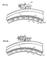
- Figure 3a shows the ring 215 and flange 209 in a first configuration.
- the openings 217 in the ring 215 generally align with the openings 213 in the first flange 207. This allows a first flow rate of cooling air from the annular chamber 127 to reach the nozzle flaps.
- the openings 213 align with the fasteners 131 of the nozzle flap hinge assembly to provide access during assembly.
- an axial gap exists between the ring 215 and the flange 209.
- Rotation of the drive shaft 225a causes the drive crank 221 to move the ring 215 relative to the flange 207.
- the ring 215 moves both transversely and axially relative to the flange 209.
- the idler cranks 219 ensure that the ring 215 retains a parallel orientation to the flange during movement.
- the axial gap between the ring 215 and the flange 209 narrows. To avoid vibration of the ring 215 against the flange 209, the gap preferably remains (albeit smaller) when in the second configuration.
- FIG. 3b shows the ring 215 and flange 209 in a second configuration.
- the openings 217 in the ring 215 in this second configuration are misaligned with the openings 213 in the first flange 207. Since the openings 213, 217 still overlap, some cooling air can reach the nozzle flaps.
- the valve assembly 200 allows a second flow rate of cooling air (less than the first flow rate) to reach the nozzle flaps.
- the ring 215 could misalign the openings 213, 217 so that no overlap occurs. In this alternative, the second flow rate would be zero.
- the teardrop shape of the opening 213 helps the valve assembly accommodate fluctuations in the positioning of the ring 215 relative to flange 207 without significantly altering flow rate. In other words, the teardrop shape of the opening 213 reduces the sensitivity of flow rate changes due to tolerances in the positioning of the ring 215 relative to the flange 207.
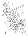
- Figures 4a, 4b and 5 show the actuator module 203 of the valve assembly 200.
- the actuator module 203 is a parallelogram linkage.
- a frame 227, a carrier 229 and two cranks 231, 233 form the parallelogram.
- the frame 227 mounts to brackets on the third section 121 of the swivel duct using conventional techniques.
- the upstream end of the frame 227 includes a flange 235.
- the crank 231 pivotally mounts to the flange 235 using conventional techniques.
- the downstream end of the frame 227 includes an upper flange 237a and a lower flange 237b.
- the shaft 225a described earlier as being located in the annular chamber 127 of the nozzle section, extends outwardly from inside the nozzle section 113 and towards the lower flange 237b.
- the upper end of the shaft 225a has a plate 259a.
- the plate 259a corresponds to a plate 259b on an upper shaft 225b.
- Fasteners (not shown) secure the plates 259a, 259b together to create a continuous shaft 225a, 225b.
- the shaft 225b extends through both flanges 237a, 237b.
- the crank 231 rigidly mounts to the shaft 225b between the flanges 237a, 237b.
- a spring 261 surrounds the shaft 225b and abuts the lower flange 237b.
- the spring 261 urges the upper shaft 225b and the crank 231 away from the lower flange 237b.
- the spring 261 automatically retracts the upper shaft 225b from the lower shaft 225b upon disconnection in order to aid the installation/removal of the nozzle section 113.
- the cranks 231, 233 also pivotally mount to the carrier 229 using conventional techniques.
- the carrier 229 can move fore and aft relative to the frame 227.
- the fore and aft movement of the carrier rotates the cranks 231, 233.
- Rotation of the crank 231 causes the shaft 225 to rotate and to actuate the ring 215.
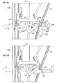
- Figure 4a shows the actuator module 203 in the first configuration.
- Figure 4b shows the actuator module 203 in the second configuration.
- the actuator module 203 limits the fore movement of the carrier 229 by allowing the carrier 229 to abut a section of the frame 227.
- the actuator module 203 does not limit the aft movement of the carrier 229.
- the valve assembly 200 preferably uses spring loading to urge the actuator module 203 to either the first configuration or the second configuration.
- the actuator module 203 includes a spring 239 surrounding arod 241. Retainers 243 at each end of the rod 241 help compress the spring and mount the assembly.
- the retainer 243 at one end of the rod 241 rotatably mounts to the carrier 229 using conventional techniques.
- the other retainer 243 at the opposite end of the rod 241 rotatably mounts to a pair of angle brackets 245 secured to the frame 227 using conventional techniques.
- the valve assembly 200 urges the actuator module 203 to either the first configuration or the second configuration by arranging the pivotpoints so as to produce an over center condition somewhere between the first and second configurations.
- the spring 239 can urge the carrier 229 to the first configuration ( Figure 4a) or to the second configuration ( Figure 4b). In the first configuration, the angle between the spring 239 and the carrier 229 is steep. The spring 239 will only transmit a small amount of force to the carrier.
- the spring 239 will passes the over center position.
- the direction of the spring force reverses when passing the over center position.
- the angle between the spring 239 and the carrier 229 is shallower than the first configuration.
- the spring 239 will transmit a greater amount of force to the carrier 229. This additional force ensures that the carrier 229 remains in the second configuration.
- the upstream end of the carrier 229 extends over the second section 119 of the swivel duct
- the upstream end of the carrier includes a cam follower assembly.
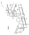
- Figure 6 shows a bottom view of the cam follower assembly (the side shown faces the engine 100).
- the cam follower assembly comprises a pair of rollers 247 and a guide 249 mounted to the carrier 229 using conventional techniques. The purpose of the cam follower assembly will become clear below.
- the exterior of the second section 119 of the swivel duct includes a cam 251.
- the cam 251 mounts to the second section 119 of the swivel duct using conventional techniques such as with brackets and fasteners.
- the cam 251 includes a first straight section 253 with a tapered tip, a second straight section 255 and a curved section 257 between the straight sections 253, 255.
- the cam follower assembly can receive the cam 251.
- the cam follower assembly Since the cam 251 mounts to the second section 119 of the swivel duct (which can rotate relative to the third section 121 of the swivel duct), the cam follower assembly only receives the cam 251 when in the first configuration. As the engine 100transitions to the second configuration, the cam 251 departs the cam follower assembly and travels to the opposite side of the engine 100 (since the second section 119 of the swivel duct rotate approximately 180° relative to the third section 121 of the swivel duct).
- the cam 251 While located within the cam follower assembly, the cam 251 performs several tasks. First, the cam 251 prevents movement of the carrier 229 in the first configuration. In the first configuration, the second straight section 255 of the cam 251 resides between the rollers 247. In other words, the cam 251 defines the aft movement limit of the carrier 229.
- the cam 251 actuates the carrier 229. Specifically, the cam 251 moves the carrier 229 to the second configuration as the engine 100 transitions. During transition to the second configuration, the second section 119 of the swivel duct begins rotating relative to the third section 121 of the swivel duct This movement places the curved section 257 of the cam 251 between the rollers 247. To accept the curved section 257, the rollers 247 cause the carrier to move forward into the second configuration. Further rotation of the second section 119 of the swivel duct places the first straight section 253 of the cam 251 between the rollers 247. Eventually, the cam 251 departs the cam follower assembly. This leaves the carrier 227 in the second configuration.
- the tapered tip of the first straight section 253 of the cam 251 enters the cam follower assembly.
- the guide 249 helps place the first straight section 253 of the cam 251 between the rollers 247.
- the cam 251 could have any suitable shape to ensure a smooth transition of the carrier 229 from the first configuration to the second configuration.
- the cam 251 could extend the entire distance (one half the circumference) that the second section 119 of the swivel duct travels from the first configuration to the second configuration.
- the shorter cam 251 described above is preferred for weight savings.
- the engine 100 requires the most amount of cooling air to the nozzle flaps. Accordingly, the present invention orients the valve assembly 200 ( e.g. Figure 3a) to allow the greatest amount of cooling air to pass therethrough.
- the engine 100 does not require as much cooling air to the nozzle flaps (since the afterburner does not operate). Accordingly, the present invention orients the valve assembly 200 ( e.g. Figure 3b) to reduce the amount of cooling air that passes therethrough.
- the valve assembly 200 preferably only allows the necessary amount of cooling air to reach the nozzle flaps in the second configuration. In other words, the valve assembly 200 preferably does not oversupply cooling air to the nozzle flaps in the STOVL configuration.
- the "surplus" air that the valve assembly 200 does not divert to the nozzle flaps remains in the bypass duct 115. Remaining in the bypass duct 115, this surplus air can produce additional thrust in the engine 100. Any amount of additional thrust is beneficial to the aircraft when in the STOVL configuration.
- valve assembly 200 Another benefit of the present invention is the ability of the valve assembly 200 to operate without a discrete motor. As discussed earlier, the rotation of the cam 251 mounted on the second section 119 of the swivel duct actuates the valve assembly. 200.
- the motor (not shown) that rotates the swivel duct is separate from the valve assembly 200. In other words, the present invention utilizes the motor from a different system of the engine 100 to actuate the valve assembly 200.
Landscapes
- Engineering & Computer Science (AREA)
- Mechanical Engineering (AREA)
- General Engineering & Computer Science (AREA)
- Chemical & Material Sciences (AREA)
- Combustion & Propulsion (AREA)
- Control Of Turbines (AREA)
- Structures Of Non-Positive Displacement Pumps (AREA)
- Lift Valve (AREA)
- Supercharger (AREA)
Abstract
Description
- This invention relates to a valve assembly for a gas turbine engine. Specifically, this invention relates to a valve assembly that controls the amount of cooling air supplied to a nozzle of a gas turbine engine.
- The major components of a gas turbine engine include (beginning at the upstream end, or inlet) a compressor section, a burner section, a turbine section, and a nozzle section. The engine may have an afterburner section between the turbine section and the nozzle section.
- If the engine is a turbofan, then the compressor section includes a fan section at the upstream end. After passing the fan section, the turbofan engine separates the air into two flow paths. A primary flow (also referred to as core engine flow) enters the remainder of the compressor section, mixes with fuel, and combusts in the burner section. The gases exit the burner section to power the turbine section.
- A secondary flow (also referred to as bypass flow) avoids the remainder of the compressor section, the burner section and the turbine section. Instead, the secondary flow travels through a duct to a location downstream of the turbine section. The secondary flow mixes with the primary flow downstream of the turbine section.
- As necessary, the afterburner section could augment the thrust of the engine by igniting additional fuel downstream of the turbine section. The flow then exits the engine through the nozzle.
- The engine must supply cooling air to the nozzle in order to protect the nozzle components from the high temperature exhaust. Typically, the engine diverts secondary flow from the fan section to cool the nozzle section.
- The greatest demand for cooling air to the nozzle occurs when the afterburner operates. As an example, the pilot operates the engine at maximum thrust (with the afterburner operating) in a conventional take-off and landing (CTOL) configuration. The CTOL configuration requires the greatest amount of cooling air to the nozzle.
- Certain non-augmented operations of the engine (i.e. without the afterburner operating) also require cooling air. However, the amount of cooling air need is a reduced amount from augmented operations. As an example, a short take-off vertical landing (STOVL) configuration requires maximum non-augmented thrust from the engine. The non-augmented exhaust, while still at an elevated temperature, exhibits a lower temperature than during augmented operations. Accordingly, the engine can accept a reduced supply of cooling air to the nozzle when in the STOVL configuration.
- Conventional valve assemblies have never compensated for the reduced need for cooling air in the STOVL configuration.
- It is an object of the present invention in its preferred embodiment at least to provide a new and improved valve assembly.
- It is a further object of the present invention in its preferred embodiment at least to provide a valve assembly that provides cooling air to a nozzle of a gas turbine engine.
- It is a further object of the present invention in its preferred embodiment at least to provide a valve assembly that adjusts the rate of cooling air provided to the nozzle.
- It is a further object of the present invention in its preferred embodiment at least to provide a valve assembly that adjusts the cooling air flow rate depending on engine configuration.
- It is a further object of the present invention in its preferred embodiment at least to provide a passive valve assembly.
- It is a further object of the present invention in its preferred embodiment at least to provide a valve assembly that uses a passive actuator.
- It is a further object of the present invention in its preferred embodiment at least to provide an actuator that does not require a discrete motor.
- It is a further object of the present invention in its preferred embodiment at least to provide a lightweight valve assembly.
- It is a further object of the present invention in its preferred embodiment at least to provide a valve assembly that increases the available thrust of the engine during certain configurations.
- From a first broad aspect the present invention provides a gas turbine engine, comprising: a compressor section; a burner section; a turbine section; an afterburner section; a nozzle movable between a first configuration and a second configuration; and a valve assembly for supplying cooling air to said nozzle. The valve assembly reduces the cooling air to the nozzle as the nozzle approaches the second configuration.
- From a second broad aspect the present invention provides a nozzle for discharging exhaust from a gas turbine engine, comprising: a first section; a second section movable relative to the first section between a first configuration and a second configuration; a plurality of flaps defining an exit for the exhaust; and a valve assembly providing cooling air to the flaps. The valve assembly reduces the cooling air to the flaps as the nozzle approaches the second configuration.
- From a third broad aspect the present invention provides a valve assembly for a nozzle of a gas turbine engine comprising: a first member having openings that receive cooling air; a second member placed adjacent the first member and having openings that receive the cooling air from the first member; and an actuator for moving the first member from a first position, which allows a first flow rate of cooling air to pass through the openings, to a second position, which allows a second flow rate of cooling air to pass through the openings. The second flow rate is less than the first flow rate.
- Other uses and advantages of the present invention will become apparent to those skilled in the art upon reference to the specification and the drawings, in which:
- Figure 1a is a partial cross-sectional view of an engine of the present invention in a first configuration;
- Figure 1b is a partial cross-sectional view of the engine of Figure 1a in a second configuration;
- Figure 2 is a cross-sectional perspective view of a portion of the engine in Figure 1a;
- Figure 3a is an elevational view, looking downstream, of a portion of the engine in Figure 1a in a first configuration;
- Figure 3b is the portion of the engine in Figure 3a in a second configuration;
- Figure 4a is a plan view of the portion of the engine in Figure 1a in the first configuration;
- Figure 4b is the portion of the engine in Figure 4a in the second configuration;
- Figure 5 is a perspective view of the portion of the engine in Figure 4b; and
- Figure 6 is a detailed perspective view of a portion of the engine in Figure 1a.
-
- Figures 1a and 1b display an
engine 100 of the present invention in two different configurations. Figure 1a shows theengine 100 in a first configuration, such as a conventional take-off and landing (CTOL) configuration. Figure 1b shows theengine 100 in a second configuration, such as a short take-off vertical landing (STOVL) configuration. Figure 1b also shows, in phantom line, theengine 100 in transition between the CTOL and STOVL configurations. - The
engine 100 has aninlet 101, a compressor section 103, aburner section 107, aturbine section 109, an afterburner section 111, and anozzle section 113. The compressor section 103 includes afan section 105 at the upstream end. Theengine 100 also includes abypass duct 115 for the secondary flow of air. The air flows through theengine 100 in the direction indicated by arrow F. - The
nozzle section 113 includes a three bearing swivel duct secured to the afterburner section 111 and a nozzle downstream of the duct. The three bearing swivel duct has threesections first section 117 rotatably mounts to the afterburner section 111. Thesecond section 119 rotatably mounts to thefirst section 117. Finally, thethird section 121 rotatably mounts to thesecond section 119. Conventional motors (not shown) can rotate thesections - The nozzle can be a conventional flap-type convergent-
divergent nozzle 123 or any other suitable nozzle. Thenozzle 123 secures to thethird section 121 of the swivel duct. - The
nozzle section 113 includes aliner 125. Theliner 125 separates the outer structure of thenozzle section 113 from the hot exhaust gases travelling through the nozzle section. Theliner 125 and the outer structure of thenozzle section 113 form anannular chamber 127. Theengine 100 distributes cooling air through the annular chamber to cool theliner 125. After cooling theliner 125, the cooling air continues downstream to cool the nozzle flaps. A bleed (not shown) from thebypass duct 115 supplies the cooling air to thenozzle section 113 using conventional techniques. - The present invention provides a
valve assembly 200 that controls the amount of cooling air supplied to the nozzle flaps. All of the components of thevalve assembly 200 described below are preferably made from a suitable aerospace grade material. - The
valve assembly 200 has threemodules first module 201 comprises a valve and associated support linkages. Thesecond module 203 comprises an actuator. Athird module 205 comprises an activation cam. Each module will be described in more detail below. - Figure 2 is a cross-sectional, perspective view of a portion of the
nozzle section 113. For clarity, the figure shows thenozzle section 113 without theliner 115. Thenozzle 123 secures to thethird section 121 of the swivel duct using conventional techniques such as with fasteners (not shown). - The
nozzle 123 includes aflange 129. Theflange 129 extends inwardly from the outer structure of thenozzle 123. A hinge assembly (not shown) for the nozzle flaps mounts to theflange 129 usingsuitable fasteners 131. - The
nozzle 123 also includes afirst ring 207 upstream of theflange 129. Thering 207 could have an L-shape in cross-section, with apanel 209 extending radially and a panel 211 extending longitudinally. Alternatively, thering 207 could have any suitable shape. Thering 207 is preferably integral with the outer structure of thenozzle 123. Alternatively, thering 207 could mount to the outer structure of thenozzle 123 using conventional techniques (not shown). - The panel 211 helps support the
liner 125. Thepanel 209 hasopenings 213 therethrough. Although shown as having a teardrop shape, theopenings 213 could have any suitable shape. The benefit of the teardrop shape is discussed below. - The
nozzle 123 also includes asecond ring 215 upstream of thefirst ring 207. Thering 215 is preferably flat and resides adjacent thefirst panel 209. However, thering 215 could have any other suitable shape. Thering 215 hasopenings 217 therethrough. Although shown as rectangular, theopenings 217 could have any suitable shape. - Differently than the
ring 207, thering 215 preferably movably mounts to the outer structure of thenozzle 123. Thering 215 mounts to the outer structure of thenozzle 123 using a plurality of cranks. Most of the cranks areidler cranks 219. One of the cranks is preferably a drive crank 221. - The idler cranks 219 pivotally mount to
flanges 223 on thering 215 and to the outer structure of thenozzle 113 using conventional techniques such as with bushings, washers and fasteners. - The drive crank 221 pivotally mounts to the
flange 223 on thering 215 in a fashion similar to the idler cranks 219. Differently than the idler cranks 219, the drive crank 221 rigidly secures to adrive shaft 225a using conventional techniques. - Figure 3a shows the
ring 215 andflange 209 in a first configuration. In this first configuration, theopenings 217 in thering 215 generally align with theopenings 213 in thefirst flange 207. This allows a first flow rate of cooling air from theannular chamber 127 to reach the nozzle flaps. Also note in Figure 3a that theopenings 213 align with thefasteners 131 of the nozzle flap hinge assembly to provide access during assembly. Also in this first configuration, an axial gap exists between thering 215 and theflange 209. - Rotation of the
drive shaft 225a causes the drive crank 221 to move thering 215 relative to the flange 207.Specifically, thering 215 moves both transversely and axially relative to theflange 209. The idler cranks 219 ensure that thering 215 retains a parallel orientation to the flange during movement. In the second configuration, the axial gap between thering 215 and theflange 209 narrows. To avoid vibration of thering 215 against theflange 209, the gap preferably remains (albeit smaller) when in the second configuration. - Movement of the
ring 215 from the first configuration to the second configuration alters the alignment of theopenings ring 215 andflange 209 in a second configuration. Theopenings 217 in thering 215 in this second configuration are misaligned with theopenings 213 in thefirst flange 207. Since theopenings valve assembly 200 allows a second flow rate of cooling air (less than the first flow rate) to reach the nozzle flaps. Alternatively, thering 215 could misalign theopenings - Since the travel distance of the
ring 215 is relatively short, the teardrop shape of theopening 213 helps the valve assembly accommodate fluctuations in the positioning of thering 215 relative to flange 207 without significantly altering flow rate. In other words, the teardrop shape of theopening 213 reduces the sensitivity of flow rate changes due to tolerances in the positioning of thering 215 relative to theflange 207. - Figures 4a, 4b and 5 show the
actuator module 203 of thevalve assembly 200. Generally speaking, theactuator module 203 is a parallelogram linkage. Aframe 227, acarrier 229 and twocranks - The
frame 227 mounts to brackets on thethird section 121 of the swivel duct using conventional techniques. The upstream end of theframe 227 includes aflange 235. The crank 231 pivotally mounts to theflange 235 using conventional techniques. The downstream end of theframe 227 includes anupper flange 237a and alower flange 237b. - The
shaft 225a, described earlier as being located in theannular chamber 127 of the nozzle section, extends outwardly from inside thenozzle section 113 and towards thelower flange 237b. The upper end of theshaft 225a has aplate 259a. Theplate 259a corresponds to aplate 259b on anupper shaft 225b. Fasteners (not shown) secure theplates continuous shaft - The
shaft 225b extends through bothflanges ring 215 within theannular chamber 127, thecrank 231 rigidly mounts to theshaft 225b between theflanges - A
spring 261 surrounds theshaft 225b and abuts thelower flange 237b. During installation of the nozzle section 113 (which includes thelower shaft 225a), thespring 261 urges theupper shaft 225b and thecrank 231 away from thelower flange 237b. In other words, thespring 261 automatically retracts theupper shaft 225b from thelower shaft 225b upon disconnection in order to aid the installation/removal of thenozzle section 113. After installation of thenozzle section 113, sufficiently elongated fasteners can extend through the holes in theplates plates - The
cranks carrier 229 using conventional techniques. In this parallelogram arrangement, thecarrier 229 can move fore and aft relative to theframe 227. The fore and aft movement of the carrier rotates thecranks crank 231 causes the shaft 225 to rotate and to actuate thering 215. - Figure 4a shows the
actuator module 203 in the first configuration. Figure 4b shows theactuator module 203 in the second configuration. Theactuator module 203 limits the fore movement of thecarrier 229 by allowing thecarrier 229 to abut a section of theframe 227. Theactuator module 203 does not limit the aft movement of thecarrier 229. Another feature of thevalve assembly 200, described below, limits the aft movement of the carrier. - The
valve assembly 200 preferably uses spring loading to urge theactuator module 203 to either the first configuration or the second configuration. Theactuator module 203 includes aspring 239 surroundingarod 241.Retainers 243 at each end of therod 241 help compress the spring and mount the assembly. Theretainer 243 at one end of therod 241 rotatably mounts to thecarrier 229 using conventional techniques. Theother retainer 243 at the opposite end of therod 241 rotatably mounts to a pair ofangle brackets 245 secured to theframe 227 using conventional techniques. - The
valve assembly 200 urges theactuator module 203 to either the first configuration or the second configuration by arranging the pivotpoints so as to produce an over center condition somewhere between the first and second configurations. Using the over center arrangement, thespring 239 can urge thecarrier 229 to the first configuration (Figure 4a) or to the second configuration (Figure 4b). In the first configuration, the angle between thespring 239 and thecarrier 229 is steep. Thespring 239 will only transmit a small amount of force to the carrier. - As the
actuator module 203 travels to the second configuration, thespring 239 will passes the over center position. The direction of the spring force reverses when passing the over center position. In the second configuration, the angle between thespring 239 and thecarrier 229 is shallower than the first configuration. Thus, thespring 239 will transmit a greater amount of force to thecarrier 229. This additional force ensures that thecarrier 229 remains in the second configuration. - The upstream end of the
carrier 229 extends over thesecond section 119 of the swivel duct The upstream end of the carrier includes a cam follower assembly. Figure 6 shows a bottom view of the cam follower assembly (the side shown faces the engine 100). The cam follower assembly comprises a pair ofrollers 247 and aguide 249 mounted to thecarrier 229 using conventional techniques. The purpose of the cam follower assembly will become clear below. - The exterior of the
second section 119 of the swivel duct includes acam 251. Thecam 251 mounts to thesecond section 119 of the swivel duct using conventional techniques such as with brackets and fasteners. Thecam 251 includes a firststraight section 253 with a tapered tip, a secondstraight section 255 and acurved section 257 between thestraight sections cam 251. - Since the
cam 251 mounts to thesecond section 119 of the swivel duct (which can rotate relative to thethird section 121 of the swivel duct), the cam follower assembly only receives thecam 251 when in the first configuration. As the engine 100transitions to the second configuration, thecam 251 departs the cam follower assembly and travels to the opposite side of the engine 100 (since thesecond section 119 of the swivel duct rotate approximately 180° relative to thethird section 121 of the swivel duct). - While located within the cam follower assembly, the
cam 251 performs several tasks. First, thecam 251 prevents movement of thecarrier 229 in the first configuration. In the first configuration, the secondstraight section 255 of thecam 251 resides between therollers 247. In other words, thecam 251 defines the aft movement limit of thecarrier 229. - Second, the
cam 251 actuates thecarrier 229. Specifically, thecam 251 moves thecarrier 229 to the second configuration as theengine 100 transitions. During transition to the second configuration, thesecond section 119 of the swivel duct begins rotating relative to thethird section 121 of the swivel duct This movement places thecurved section 257 of thecam 251 between therollers 247. To accept thecurved section 257, therollers 247 cause the carrier to move forward into the second configuration. Further rotation of thesecond section 119 of the swivel duct places the firststraight section 253 of thecam 251 between therollers 247. Eventually, thecam 251 departs the cam follower assembly. This leaves thecarrier 227 in the second configuration. - As the
engine 100 returns to the first configuration, the tapered tip of the firststraight section 253 of thecam 251 enters the cam follower assembly. Theguide 249 helps place the firststraight section 253 of thecam 251 between therollers 247. - Further rotation of the
second section 119 of the swivel duct towards the first configuration places thecurved section 257 of thecam 251betweenthe rollers 247. To accept thecurved section 257, therollers 247 cause the carrier to move aft into the first configuration. Further rotation of thesecond section 119 of the swivel duct places the secondstraight section 255 of thecam 251 between therollers 247. Eventually, the firststraight section 253 of thecam 251 returns to the position between therollers 247. The engine has just completed a cycle from the first configuration, to the second configuration, and back to the first configuration. - The
cam 251 could have any suitable shape to ensure a smooth transition of thecarrier 229 from the first configuration to the second configuration. In addition, thecam 251 could extend the entire distance (one half the circumference) that thesecond section 119 of the swivel duct travels from the first configuration to the second configuration. However, theshorter cam 251 described above is preferred for weight savings. - In the CTOL configuration, the
engine 100 requires the most amount of cooling air to the nozzle flaps. Accordingly, the present invention orients the valve assembly 200 (e.g. Figure 3a) to allow the greatest amount of cooling air to pass therethrough. - In the STOVL configuration, however, the
engine 100 does not require as much cooling air to the nozzle flaps (since the afterburner does not operate). Accordingly, the present invention orients the valve assembly 200 (e.g. Figure 3b) to reduce the amount of cooling air that passes therethrough. - The
valve assembly 200 preferably only allows the necessary amount of cooling air to reach the nozzle flaps in the second configuration. In other words, thevalve assembly 200 preferably does not oversupply cooling air to the nozzle flaps in the STOVL configuration. The "surplus" air that thevalve assembly 200 does not divert to the nozzle flaps remains in thebypass duct 115. Remaining in thebypass duct 115, this surplus air can produce additional thrust in theengine 100. Any amount of additional thrust is beneficial to the aircraft when in the STOVL configuration. - Another benefit of the present invention is the ability of the
valve assembly 200 to operate without a discrete motor. As discussed earlier, the rotation of thecam 251 mounted on thesecond section 119 of the swivel duct actuates the valve assembly. 200. The motor (not shown) that rotates the swivel duct is separate from thevalve assembly 200. In other words, the present invention utilizes the motor from a different system of theengine 100 to actuate thevalve assembly 200. - The present invention has been described in connection with the preferred embodiments of the various figures. It is to be understood that other similar embodiments may be used or modifications and additions may be made to the described embodiment for performing the same function of the present invention without deviating therefrom. Therefore, the present invention should not be limited to any single embodiment, but rather construed in breadth and scope in accordance with the recitation of the appended claims.
Claims (17)
- A gas turbine engine (100), comprising:wherein said valve assembly (200) reduces said cooling air to said nozzle (113) as said nozzle approaches said second configuration.a compressor section (103);a burner section (107);a turbine section (109);an afterburner section (111);a nozzle movable (113) between a first configuration and a second configuration; anda valve assembly (200) for supplying cooling air to said nozzle (113),
- The engine (100) as recited in claim 1, wherein said nozzle (113) is a three bearing swivel duct.
- The engine (100) as recited in claim 1 or 2, wherein said first configuration is a conventional take-off and landing (CTOL) configuration and said second configuration is a full short take-off vertical landing (STOVL) configuration.
- The engine (100) as recited in claim 3, wherein said afterburner (111) does not operate in said STOVL configuration.
- The engine (100) as recited in any preceding claim, wherein said valve assembly (200) receives said cooling air from said compressor section (103).
- The engine (100) as recited in claim 5, wherein said compressor section (103) includes a fan section (105) and said valve assembly (200) receives said cooling air from said fan section (105).
- The engine as recited in any preceding claim, further comprising an actuator to move said nozzle (113) between said first configuration and said second configuration, wherein said actuator also drives said valve assembly (200).
- A nozzle (113) to discharge exhaust from a gas turbine engine(100), comprising:wherein said valve assembly reduces said cooling air to said flaps as said nozzle (113) approaches said second configuration.a first section;a second section movable relative to said first section between a first configuration and a second configuration;a plurality of flaps defining an exit (123) for said exhaust; anda valve assembly (200) providing cooling air to said flaps;
- The nozzle (113) as recited in claim 8, wherein said nozzle (113) is a three bearing swivel duct.
- The nozzle (113) as recited in claim 9, wherein said first section comprises an intermediate duct (119) of said three bearing swivel duct and said second section comprises a rear duct (121) of said three bearing swivel duct.
- The nozzle (113) as recited in claim 9 or 10, wherein said three bearing swivel duct includes an actuator for moving said three bearing swivel duct between said first configuration and said second configuration, and said actuator also drives said valve assembly (200).
- The nozzle (113) as recited in any of claims 8 to 11, wherein said first configuration is a conventional take-off and landing (CTOL) configuration and said second configuration is a full short take-off vertical landing (STOVL) configuration.
- A valve assembly (200) for a nozzle of a gas turbine engine (100), comprising:wherein said second flow rate is less than said first flow rate.a first member (215) having openings (217) that receive cooling air,a second member (207) placed adjacent said first member and having openings (213)that receive said cooling air from said first member (215); andan actuator (203) for moving said first member (215) from a first position, which allows a first flow rate of said cooling air to pass through said openings (213,217), to a second position, which allows a second flow rate of said cooling air to pass through said openings(213,217);
- The valve assembly (200) as recited in claim 13, wherein said first(215) and second members (207) are annular.
- The valve assembly (200) as recited in claim 13 or 14, wherein said actuator (203) rotates said first member.
- The valve assembly (200) as recited in any of claims 13 to 15, wherein said first position occurs when said engine (100) is in a conventional take-off and landing (CTOL) configuration and said second position occurs when said engine (100) is in a full short take-off vertical landing (STOVL) configuration.
- The valve assembly (200) as recited in any of claims 13 to 16, wherein said actuator is part of a three bearing swivel duct (113).
Applications Claiming Priority (2)
| Application Number | Priority Date | Filing Date | Title |
|---|---|---|---|
| US109109 | 2002-03-27 | ||
| US10/109,109 US6694723B2 (en) | 2002-03-27 | 2002-03-27 | Valve assembly for gas turbine engine |
Publications (2)
| Publication Number | Publication Date |
|---|---|
| EP1348835A2 true EP1348835A2 (en) | 2003-10-01 |
| EP1348835A3 EP1348835A3 (en) | 2005-08-17 |
Family
ID=27804399
Family Applications (1)
| Application Number | Title | Priority Date | Filing Date |
|---|---|---|---|
| EP03251927A Withdrawn EP1348835A3 (en) | 2002-03-27 | 2003-03-27 | Valve assembly for gas turbine engine |
Country Status (4)
| Country | Link |
|---|---|
| US (1) | US6694723B2 (en) |
| EP (1) | EP1348835A3 (en) |
| CA (1) | CA2422553C (en) |
| SG (1) | SG119178A1 (en) |
Cited By (6)
| Publication number | Priority date | Publication date | Assignee | Title |
|---|---|---|---|---|
| EP1722071A2 (en) | 2005-04-28 | 2006-11-15 | United Technologies Corporation | Gas turbine engine air valve assembly and a method for reengineering an engine configuration |
| FR2900445A1 (en) * | 2006-04-28 | 2007-11-02 | Snecma Sa | TURBOREACTOR COMPRISING A POST COMBUSTION CHANNEL COOLED BY A VARIABLE FLOW VENTILATION FLOW |
| EP1998007A3 (en) * | 2007-05-31 | 2012-01-11 | United Technologies Corporation | Single actuator controlled rotational flow balance system |
| EP3002418A1 (en) * | 2014-10-01 | 2016-04-06 | United Technologies Corporation | Actuation apparatus for an air modulating system of a gas turbine |
| EP3026248A1 (en) * | 2014-10-01 | 2016-06-01 | United Technologies Corporation | Synchronized air modulating system |
| US9835043B2 (en) | 2014-10-01 | 2017-12-05 | United Technologies Corporation | Guided binding-resistant actuation apparatus and method |
Families Citing this family (19)
| Publication number | Priority date | Publication date | Assignee | Title |
|---|---|---|---|---|
| US7584601B2 (en) * | 2004-09-03 | 2009-09-08 | Metcalfe Iii Tristram Walker | Charged particle thrust engine |
| US7287504B2 (en) * | 2004-10-29 | 2007-10-30 | Siemens Vdo Automotive Canada Inc. | Over-center actuator |
| US7581382B2 (en) * | 2005-04-28 | 2009-09-01 | United Technologies Corporation | Gas turbine engine air valve assembly |
| ATE523682T1 (en) * | 2005-09-27 | 2011-09-15 | Volvo Aero Corp | ARRANGEMENT FOR DRIVING AN AIRCRAFT, AIRCRAFT AND EXHAUST NOZZLE FOR A JET ENGINE |
| US20080072604A1 (en) * | 2006-09-26 | 2008-03-27 | United Technologies Corporation | Pressure balance control for gas turbine engine nozzle |
| US7854124B2 (en) * | 2006-10-27 | 2010-12-21 | United Technologies Corporation | Combined control for supplying cooling air and support air in a turbine engine nozzle |
| US7870741B2 (en) * | 2007-05-25 | 2011-01-18 | General Electric Company | Turbine engine valve assembly and method of assembling the same |
| US8286416B2 (en) * | 2008-04-02 | 2012-10-16 | Pratt & Whitney Rocketdyne, Inc. | Valve system for a gas turbine engine |
| US8402744B2 (en) * | 2008-03-22 | 2013-03-26 | Pratt & Whitney Rocketdyne, Inc. | Valve system for a gas turbine engine |
| US8578716B2 (en) * | 2008-03-22 | 2013-11-12 | United Technologies Corporation | Valve system for a gas turbine engine |
| US8240126B2 (en) * | 2008-03-22 | 2012-08-14 | Pratt & Whitney Rocketdyne, Inc. | Valve system for a gas turbine engine |
| GB2462413B (en) * | 2008-08-04 | 2011-03-02 | Rolls Royce Plc | An actuator arrangement |
| US8197187B2 (en) * | 2008-12-29 | 2012-06-12 | Caterpillar Inc. | Inspection hole plug with a ball swivel |
| US8616850B2 (en) | 2010-06-11 | 2013-12-31 | United Technologies Corporation | Gas turbine engine blade mounting arrangement |
| US8967952B2 (en) | 2011-12-22 | 2015-03-03 | United Technologies Corporation | Gas turbine engine duct blocker that includes a duct blocker rotor with a plurality of roller elements |
| US9011082B2 (en) | 2011-12-22 | 2015-04-21 | United Technologies Corporation | Gas turbine engine duct blocker with rotatable vane segments |
| CN103985407A (en) | 2013-02-07 | 2014-08-13 | 辉达公司 | DRAM with Segmented Page Configuration |
| WO2021072070A1 (en) * | 2019-10-09 | 2021-04-15 | Kitty Hawk Corporation | Short takeoff and landing vehicle with forward swept wings |
| US11247773B2 (en) | 2020-06-12 | 2022-02-15 | Kitty Hawk Corporation | Pylon mounted tilt rotor |
Citations (1)
| Publication number | Priority date | Publication date | Assignee | Title |
|---|---|---|---|---|
| US3429509A (en) * | 1967-05-31 | 1969-02-25 | United Aircraft Corp | Cooling scheme for a three bearing swivel nozzle |
Family Cites Families (21)
| Publication number | Priority date | Publication date | Assignee | Title |
|---|---|---|---|---|
| US2682238A (en) * | 1952-05-12 | 1954-06-29 | Russell Lacey Mfg Company Inc | Web severing means for tufting machines |
| US2951660A (en) * | 1956-06-25 | 1960-09-06 | James V Giliberty | Method and means for controlling the jet thrust of an aircraft |
| FR1306025A (en) * | 1961-08-08 | 1962-10-13 | Snecma | Variable blocking coefficient mixer in double-flow mixed-flow reactors |
| GB1100656A (en) * | 1965-10-04 | 1968-01-24 | Rolls Royce | Jet propulsion nozzle |
| GB1550633A (en) * | 1976-07-21 | 1979-08-15 | Gen Electric | Thrust-vectoring gas turbine engine exhaust nozzles |
| US4222233A (en) | 1977-08-02 | 1980-09-16 | General Electric Company | Auxiliary lift propulsion system with oversized front fan |
| US4502636A (en) * | 1982-04-07 | 1985-03-05 | Rolls-Royce Inc. | Variable geometry ejector nozzle for turbomachines |
| US4544098A (en) * | 1982-12-27 | 1985-10-01 | United Technologies Corporation | Cooled exhaust nozzle flaps |
| JPS59141753A (en) * | 1983-01-31 | 1984-08-14 | Fuji Heavy Ind Ltd | Thrust increasing and deflecting apparatus for use in v/stol aircraft |
| US5082209A (en) * | 1991-03-01 | 1992-01-21 | United Technologies Corporation | Thrust reverser assembly |
| EP0723075B1 (en) * | 1991-05-16 | 2001-11-21 | General Electric Company | Thermal shield for axisymmetric vectoring nozzle |
| DE4138784A1 (en) | 1991-11-26 | 1993-05-27 | Mtu Muenchen Gmbh | DEVICE FOR SEALING A GAP |
| CA2091473A1 (en) * | 1992-04-20 | 1993-10-21 | Mark J. Wagner | Bypass injector valve for variable cycle aircraft engines |
| GB2267066B (en) | 1992-05-16 | 1995-06-14 | Rolls Royce Plc | Vectorable nozzle mounting |
| US5351888A (en) | 1993-05-14 | 1994-10-04 | General Electric Company | Multi-axis vectorable exhaust nozzle |
| US5484105A (en) * | 1994-07-13 | 1996-01-16 | General Electric Company | Cooling system for a divergent section of a nozzle |
| US5706650A (en) * | 1995-08-09 | 1998-01-13 | United Technologies Corporation | Vectoring nozzle using injected high pressure air |
| US5799874A (en) | 1995-11-30 | 1998-09-01 | United Technologies Corporation | Aerodynamically controlled ejector |
| JPH1026353A (en) * | 1996-07-12 | 1998-01-27 | Mitsubishi Heavy Ind Ltd | Gas turbine combustor bypass air flow control system |
| US5816042A (en) * | 1996-12-27 | 1998-10-06 | United Technologies Corporation | Flow diverter system for multiple streams for gas turbine engines |
| US6199772B1 (en) | 1999-08-25 | 2001-03-13 | General Electric Company | Linear actuation and vectoring ring support mechanism for axisymmetric vectoring nozzle |
-
2002
- 2002-03-27 US US10/109,109 patent/US6694723B2/en not_active Expired - Lifetime
-
2003
- 2003-03-18 CA CA002422553A patent/CA2422553C/en not_active Expired - Fee Related
- 2003-03-20 SG SG200301637A patent/SG119178A1/en unknown
- 2003-03-27 EP EP03251927A patent/EP1348835A3/en not_active Withdrawn
Patent Citations (1)
| Publication number | Priority date | Publication date | Assignee | Title |
|---|---|---|---|---|
| US3429509A (en) * | 1967-05-31 | 1969-02-25 | United Aircraft Corp | Cooling scheme for a three bearing swivel nozzle |
Cited By (13)
| Publication number | Priority date | Publication date | Assignee | Title |
|---|---|---|---|---|
| EP1722071A2 (en) | 2005-04-28 | 2006-11-15 | United Technologies Corporation | Gas turbine engine air valve assembly and a method for reengineering an engine configuration |
| EP1722071A3 (en) * | 2005-04-28 | 2009-11-04 | United Technologies Corporation | Gas turbine engine air valve assembly and a method for reengineering an engine configuration |
| US8015996B2 (en) | 2005-04-28 | 2011-09-13 | United Technologies Corporation | Gas turbine engine air valve assembly |
| FR2900445A1 (en) * | 2006-04-28 | 2007-11-02 | Snecma Sa | TURBOREACTOR COMPRISING A POST COMBUSTION CHANNEL COOLED BY A VARIABLE FLOW VENTILATION FLOW |
| EP1998007A3 (en) * | 2007-05-31 | 2012-01-11 | United Technologies Corporation | Single actuator controlled rotational flow balance system |
| EP3026248A1 (en) * | 2014-10-01 | 2016-06-01 | United Technologies Corporation | Synchronized air modulating system |
| EP3002418A1 (en) * | 2014-10-01 | 2016-04-06 | United Technologies Corporation | Actuation apparatus for an air modulating system of a gas turbine |
| US9835043B2 (en) | 2014-10-01 | 2017-12-05 | United Technologies Corporation | Guided binding-resistant actuation apparatus and method |
| US10352248B2 (en) | 2014-10-01 | 2019-07-16 | United Technologies Corporation | Synchronized air modulating system |
| EP3805541A1 (en) * | 2014-10-01 | 2021-04-14 | Raytheon Technologies Corporation | Synchronized air modulating system |
| US11492977B2 (en) | 2014-10-01 | 2022-11-08 | Raytheon Technologies Corporation | Synchronized air modulating system |
| US11939924B2 (en) | 2014-10-01 | 2024-03-26 | Rtx Corporation | Synchronized air modulating system |
| EP4644685A3 (en) * | 2014-10-01 | 2026-02-25 | RTX Corporation | Synchronized air modulating system |
Also Published As
| Publication number | Publication date |
|---|---|
| EP1348835A3 (en) | 2005-08-17 |
| CA2422553C (en) | 2007-01-09 |
| US20030205043A1 (en) | 2003-11-06 |
| CA2422553A1 (en) | 2003-09-27 |
| SG119178A1 (en) | 2006-02-28 |
| US6694723B2 (en) | 2004-02-24 |
Similar Documents
| Publication | Publication Date | Title |
|---|---|---|
| US6694723B2 (en) | Valve assembly for gas turbine engine | |
| CN114991963B (en) | Three-stream engine with heat exchanger | |
| EP3483414B1 (en) | Gas turbine engine having an air-oil heat exchanger | |
| US11378009B2 (en) | Multi-mode heat rejection system for a gas turbine engine | |
| US20230212985A1 (en) | Differential geared amplification of auxiliary power unit | |
| US8826641B2 (en) | Thermal management system integrated pylon | |
| CN100404839C (en) | Tail FLADE engine | |
| US12281850B2 (en) | Multi-fluid heat exchanger | |
| US5996935A (en) | Power plants | |
| US6804947B2 (en) | Device for cooling the common nozzle of a turbojet pod | |
| US7886544B2 (en) | Propeller or propeller drive | |
| EP2085600B1 (en) | Thermal management system integrated pylon | |
| US20200208533A1 (en) | Passive blade tip clearance control system for gas turbine engine | |
| US10815814B2 (en) | Re-use and modulated cooling from tip clearance control system for gas turbine engine | |
| US20050056019A1 (en) | Integral compressor housing of gas turbine engines | |
| EP4386193B1 (en) | Thermal management system for gas turbine engine | |
| US12595066B1 (en) | Blended wing aircraft | |
| EP4105447B1 (en) | Secondary air supply system with feed pipes having sonic orifices | |
| EP0091786B1 (en) | Variable geometry nozzles for turbomachines | |
| US11905837B2 (en) | Sealing system including a seal assembly between components | |
| EP4092251B1 (en) | Flowpath assembly for gas turbine engine |
Legal Events
| Date | Code | Title | Description |
|---|---|---|---|
| PUAI | Public reference made under article 153(3) epc to a published international application that has entered the european phase |
Free format text: ORIGINAL CODE: 0009012 |
|
| AK | Designated contracting states |
Kind code of ref document: A2 Designated state(s): AT BE BG CH CY CZ DE DK EE ES FI FR GB GR HU IE IT LI LU MC NL PT RO SE SI SK TR |
|
| AX | Request for extension of the european patent |
Extension state: AL LT LV MK |
|
| PUAL | Search report despatched |
Free format text: ORIGINAL CODE: 0009013 |
|
| AK | Designated contracting states |
Kind code of ref document: A3 Designated state(s): AT BE BG CH CY CZ DE DK EE ES FI FR GB GR HU IE IT LI LU MC NL PT RO SE SI SK TR |
|
| AX | Request for extension of the european patent |
Extension state: AL LT LV MK |
|
| RIC1 | Information provided on ipc code assigned before grant |
Ipc: 7F 02K 1/82 B Ipc: 7F 01D 17/14 B Ipc: 7F 16K 3/08 B Ipc: 7F 02C 7/18 B Ipc: 7F 01D 17/10 A |
|
| 17P | Request for examination filed |
Effective date: 20060216 |
|
| AKX | Designation fees paid |
Designated state(s): AT BE BG CH CY CZ DE DK EE ES FI FR GB GR HU IE IT LI LU MC NL PT RO SE SI SK TR |
|
| 17Q | First examination report despatched |
Effective date: 20071228 |
|
| RIC1 | Information provided on ipc code assigned before grant |
Ipc: F01D 17/14 20060101ALI20130731BHEP Ipc: F02C 7/12 20060101AFI20130731BHEP |
|
| GRAP | Despatch of communication of intention to grant a patent |
Free format text: ORIGINAL CODE: EPIDOSNIGR1 |
|
| INTG | Intention to grant announced |
Effective date: 20131022 |
|
| STAA | Information on the status of an ep patent application or granted ep patent |
Free format text: STATUS: THE APPLICATION IS DEEMED TO BE WITHDRAWN |
|
| 18D | Application deemed to be withdrawn |
Effective date: 20131001 |