EP1348624A1 - Dispositif de commande du pas des pales d'un rotor d'aéronef convertible - Google Patents
Dispositif de commande du pas des pales d'un rotor d'aéronef convertible Download PDFInfo
- Publication number
- EP1348624A1 EP1348624A1 EP03290738A EP03290738A EP1348624A1 EP 1348624 A1 EP1348624 A1 EP 1348624A1 EP 03290738 A EP03290738 A EP 03290738A EP 03290738 A EP03290738 A EP 03290738A EP 1348624 A1 EP1348624 A1 EP 1348624A1
- Authority
- EP
- European Patent Office
- Prior art keywords
- axis
- pitch
- mast
- rotor
- connecting rod
- Prior art date
- Legal status (The legal status is an assumption and is not a legal conclusion. Google has not performed a legal analysis and makes no representation as to the accuracy of the status listed.)
- Granted
Links
- 230000008878 coupling Effects 0.000 claims abstract description 10
- 238000010168 coupling process Methods 0.000 claims abstract description 10
- 238000005859 coupling reaction Methods 0.000 claims abstract description 10
- 230000008859 change Effects 0.000 claims description 27
- 230000007935 neutral effect Effects 0.000 claims description 3
- 230000005540 biological transmission Effects 0.000 abstract description 2
- 230000007246 mechanism Effects 0.000 abstract description 2
- 125000004122 cyclic group Chemical group 0.000 description 21
- 230000008901 benefit Effects 0.000 description 6
- 238000006073 displacement reaction Methods 0.000 description 3
- 241000940835 Pales Species 0.000 description 2
- 206010033546 Pallor Diseases 0.000 description 2
- 238000010586 diagram Methods 0.000 description 2
- 230000002349 favourable effect Effects 0.000 description 2
- 238000012550 audit Methods 0.000 description 1
- 238000010009 beating Methods 0.000 description 1
- 238000005452 bending Methods 0.000 description 1
- 239000003638 chemical reducing agent Substances 0.000 description 1
- 239000002131 composite material Substances 0.000 description 1
- 230000014759 maintenance of location Effects 0.000 description 1
- 239000000463 material Substances 0.000 description 1
- 238000005457 optimization Methods 0.000 description 1
- 230000010355 oscillation Effects 0.000 description 1
- 244000045947 parasite Species 0.000 description 1
- 210000003456 pulmonary alveoli Anatomy 0.000 description 1
- 230000009467 reduction Effects 0.000 description 1
- 230000000717 retained effect Effects 0.000 description 1
- 230000007704 transition Effects 0.000 description 1
Images


Classifications
-
- B—PERFORMING OPERATIONS; TRANSPORTING
- B64—AIRCRAFT; AVIATION; COSMONAUTICS
- B64C—AEROPLANES; HELICOPTERS
- B64C27/00—Rotorcraft; Rotors peculiar thereto
- B64C27/32—Rotors
- B64C27/37—Rotors having articulated joints
- B64C27/41—Rotors having articulated joints with flapping hinge or universal joint, common to the blades
-
- B—PERFORMING OPERATIONS; TRANSPORTING
- B64—AIRCRAFT; AVIATION; COSMONAUTICS
- B64C—AEROPLANES; HELICOPTERS
- B64C27/00—Rotorcraft; Rotors peculiar thereto
- B64C27/22—Compound rotorcraft, i.e. aircraft using in flight the features of both aeroplane and rotorcraft
- B64C27/28—Compound rotorcraft, i.e. aircraft using in flight the features of both aeroplane and rotorcraft with forward-propulsion propellers pivotable to act as lifting rotors
-
- B—PERFORMING OPERATIONS; TRANSPORTING
- B64—AIRCRAFT; AVIATION; COSMONAUTICS
- B64C—AEROPLANES; HELICOPTERS
- B64C27/00—Rotorcraft; Rotors peculiar thereto
- B64C27/54—Mechanisms for controlling blade adjustment or movement relative to rotor head, e.g. lag-lead movement
- B64C27/58—Transmitting means, e.g. interrelated with initiating means or means acting on blades
- B64C27/59—Transmitting means, e.g. interrelated with initiating means or means acting on blades mechanical
- B64C27/605—Transmitting means, e.g. interrelated with initiating means or means acting on blades mechanical including swash plate, spider or cam mechanisms
-
- B—PERFORMING OPERATIONS; TRANSPORTING
- B64—AIRCRAFT; AVIATION; COSMONAUTICS
- B64C—AEROPLANES; HELICOPTERS
- B64C29/00—Aircraft capable of landing or taking-off vertically, e.g. vertical take-off and landing [VTOL] aircraft
- B64C29/0008—Aircraft capable of landing or taking-off vertically, e.g. vertical take-off and landing [VTOL] aircraft having its flight directional axis horizontal when grounded
- B64C29/0016—Aircraft capable of landing or taking-off vertically, e.g. vertical take-off and landing [VTOL] aircraft having its flight directional axis horizontal when grounded the lift during taking-off being created by free or ducted propellers or by blowers
- B64C29/0033—Aircraft capable of landing or taking-off vertically, e.g. vertical take-off and landing [VTOL] aircraft having its flight directional axis horizontal when grounded the lift during taking-off being created by free or ducted propellers or by blowers the propellers being tiltable relative to the fuselage
Definitions
- the invention relates to a device for controlling the pitch of the blades of a rotor of a convertible aircraft, of the known type supporting at least two wings, generally fixed, and at least one tilting rotor.
- a particularly advantageous application of the control device pitch according to the invention consists of the equipment of tilting rotors with constant velocity training for convertible aircraft, in particular of the type known and described in FR 2 791 319, FR 2 791 634 and FR 2 798 359, to which advantageously refer for further details on this subject.
- such a convertible aircraft with rotors tilting generally includes, as shown schematically on the FIG. 1, a fuselage 1, of the airplane fuselage type, supporting two fixed wings 2, for example high and raised wings relative to the fuselage 1, each wing 2 supporting itself a driving nacelle 3, housing a power unit causing a rotor 4 to rotate, shown diagrammatically by the plane of rotation of the blades of the rotor, via a transmission (not visible in Figure 1), one of which rear reducer assembly is directly driven by the power unit and housed like the latter in the fixed rear part 5 of the driving nacelle 3, the front part 6, housing the rotor mast and the hub, as well as a reduction unit before driving the rotor mast in rotation, is tiltably mounted with the rotor 4, so as to be able to switch from an airplane configuration, in which the rotor 4 is behaves like a propeller in front of a 5-6 time zone in the wind bed relating to a helicopter configuration, in which the rotor 4 'behaves like
- the tilting rotors of convertible aircraft differ from rotors, in particular main, of helicopters by the following characteristics.
- Their control range in collective pitch of the blades is very important, since the aircraft must be able to operate not only as a helicopter but also like an airplane, their control power must remain low, which imposes a beat eccentricity (i.e. the distance between the beat axis blades and the axis of rotation of the rotor) very weak, the rotors, and in particular their hub, must have great rigidity in the plane of the rotor, in order to provide a high drag mode, to overcome the risks of ground resonance, and their cyclical beat is important.
- this condition of small distance between the beat axis and the center of the articulation of the pitch lever to the pitch control rod can be observed on a three-bladed rotor with conventional pitch levers, i.e. placed substantially in the plane of the rotor disc, because the space available between the feet of successive blades is generally sufficient to accommodate such step levers.
- the beat axis of a blade corresponds substantially to the longitudinal axis of the next blade, this which prohibits for reason of geometric interference to place the step levers satisfying the above conditions.
- the problem underlying the present invention is to provide a pitch control device for the blades of a rotor called “gimbal” such as defined above, preferably rigid in its plane, and which may include minus three blades, but preferably four or more blades, while satisfying the severe requirement for a weakly negative K bond.
- An essential advantage of this pitch control device is that the inclination of said connecting rod on any radial plane (perpendicular to the axis mast) can be chosen to correspond to a no-beat link (link K) desired for the corresponding blade.
- said connecting rod remains substantially parallel to or slightly inclined on any radial plane with respect to the axis of rotation of the mast, when said blade performs angular deflections in its step range.
- the angle of inclination of said connecting rod on any radial plane, perpendicular to the axis of the mast can vary so as to provide a step-beat coupling (link K) according to a law determined according to the pitch angle of the pale, when the latter performs angular deflections in beat.
- the return is substantially L-shaped, articulated by its elbow on the connecting rod step control, by the end of one of his arms on the coach, and by the end of its other arm on the connecting rod.
- the size of the return is thus limited, while allowing good positioning of the joints of the pitch control rod and the connecting rod on the gear, and the latter on the coach, so as to provide the desired slight inclination of the connecting rod connection on the radial plane, and therefore the desired connection K.
- the connecting rod can thus, for different values of the beat, and in depending on the pitch of the corresponding blade, present an evolution of its inclination with respect to any radial plane with respect to the axis of the mast which means that this inclination, the slope of which relative to the radial plane (relative to the axis of the mast) influences the link K obtained, remains in a range of angular value limited, less than 20 °, for a pitch range extending substantially from -10 ° at 60 °, and beat values varying from -11 ° to + 11 °.
- This slight inclination of the connecting rod on any radial plane by relative to the axis of the mast, and in a substantially transverse direction by relative to the direction of the mast axis, is also favorable in terms of the size, as well as that of the development, because the change is easy to realize, the positions of the return and the connecting rod, and in particular of their joints one on the other, as well as on the pitch lever for the connecting rod connection, and on the pitch control rod and the coach, for the return, allows easily test different pas-beat link configurations, so obtain the value of the desired K bond by the corresponding inclination of the connecting rod.
- a disturbance in beat cyclic for a rotor stressed by a large cyclical beat causes a different pitch variation for two opposite blades, but the consideration overall variation in aerodynamic moment applied to the center of the head of rotor shows that this moment remains very substantially proportional to the perturbation in cyclic beat, and independent of the cyclic beat.
- this pitch control device with, for each blade, a connecting rod substantially in the radial plane relative to the axis of the mast, is more particularly adapted to a rigid rotor in drag, for which the drag movement of the blades is very small, which limits pitch variations induced by the non-trailed coupling.
- Optimization of the limitation of pitch variations induced by this pitch-trailing coupling can be obtained by placing the end of the connecting rod articulated on the pitch lever corresponding in the plane perpendicular to the axis of articulation of pitch and containing the vibration node of the cyclic drag mode.
- the arrangement of the connecting rod, projecting from the edge side leading or trailing edge of the corresponding blade, from the pitch lever of this blade can be chosen according to the desired sign of coupling or the non-trailing link for the cyclic and collective trailing modes.
- the pivot axes of the return respectively on the coach, on the connecting rod pitch control, and on the connecting rod are substantially parallel between them, as well as to the pitch change axis of the corresponding blade, in neutral position of the hub.
- the return and the connecting rod as well preferably that the pitch control rod, move substantially in a plane parallel to the axis of the mast and perpendicular to the pivot axis of the return on the coach and substantially perpendicular to the pitch change axis the corresponding blade.
- the pitch lever in protrusion towards the base of the mast on the internal radial end, with respect to the axis of the mast, a blade sleeve, torsionally rigid and torsionally linked at the foot of the blade corresponding around the pitch change axis, and surrounding said corresponding means of retention and articulation in pitch of the blade, so that the pitch control is carried out near the hub and the axis of the mast, and that this pitch control device is, by the presence of the sleeves, directly compatible with shaped hub type rotor hubs star with as many slender arms as the rotor has blades, each hub arm supporting the retaining and articulation means in pitch a corresponding blade, these hubs being known to provide good rigidity in drag while having low rigidity in flapping, by the bending of the hub arms perpendicular to their plane.
- the connecting rod is advantageously articulated on the step lever and on the return by connections and / or the return is articulated to the pitch control rod by a ball joint.
- the quadruple rotor head of FIGS. 2 and 3, for equipping a rotor 4 tilting of a convertible aircraft according to FIG. 1, comprises a rotor mast 7, rotated by its base 7a around its longitudinal axis Z-Z, and of which the axial end opposite the base 7a is connected to a hub 8 by a device 9 constant velocity drive and overall tilting around any axis of beat intersecting the axis Z-Z and perpendicular thereto, and being able to be oriented along any azimuth around the axis Z-Z, this device 9 homokinetic drive and tilting being, for example, a double pendulum device as described in FR 02 03464, housed in a housing hub 11 fixed by a ring of axial screws 12 on a hub plate 13.
- the device 10 with double balance comprises two pendulums mounted each pivoting around one respectively of two diametral drive arms of the mast 7, perpendicular to each other and to the axis Z-Z, and each of which drives the corresponding pendulum in rotation around this axis Z-Z, each of the pendulums being more articulated on the hub casing 11 by two diametrically opposed ball joints with respect to the Z-Z axis and centered substantially in a plane passing through the Z-Z axis and the diametrical axis around which the other pendulum is pivotally mounted.
- the combined device 9 for tilting and constant velocity training thus allows the rotation of the hub 8 by the mast 7 about an axis geometric rotation of the hub 8 which remains perpendicular to the plane of this hub and can therefore tilt, with the latter, in any direction around the Z-Z axis.
- the hub plate 13 is a star plate comprising as many slender arms 14 that the rotor has blades, namely four in this example, each of the arms 14 supporting retaining and articulation means of a blade in pitch around the longitudinal axis X-X of pitch change this blade, this axis X-X extending in the plane of rotation of the rotor, defined substantially by the X-X axes of pitch change of all the blades, which axes X-X intersect substantially on the axis of rotation Z-Z and are substantially perpendicular to the latter, when the rotor is at rest or in neutral position, the plane of rotation of the rotor then being substantially perpendicular to the Z-Z axis of the mast 7.
- the hub plate 13 has a central opening, coaxial with the axis Z-Z, for the passage of the mast 7, as well as, in each of its arms 14, a alveolus 15, formed in the part of the arm 14 which is adjacent to the part center of the hub plate 13, and in which is housed part 16 of the retaining means and articulation of the corresponding blade, including another part 17 is fixed on the outer end of the corresponding arm 14.
- the sleeve 18 is thus secured in torsion to a corresponding blade around the X-X axis of pitch change of this blade, thanks to the means of restraint and articulation in steps 16 and 17, which hold the blade and its sleeve 18 on an arm 14 of the hub plate 13, made for example of material composite, and having great rigidity in drag, and simultaneously a good flapping flexibility at each of its arms 14.
- the pitch control device of each blade is an external device to the hub 8, rotating with the mast 7, and which makes it possible to control the pitch of the blade sleeve 18, due to the torsional rigidity of this sleeve 18 and its joining in torsion at the foot of the corresponding blade, this control not taking place, on the sleeve 18, at a pitch lever 20 which is in protrusion under the internal radial end (relative to the axis Z-Z) of the sleeve 18, this step lever 20 being oriented along the axis Z-Z and towards the base 7a of the mast 7, that is to say on the side of the plane of rotation of the hub 8 which is situated towards the base of the mast 7, as clearly shown in Figure 3.
- the pitch control device comprises a connecting rod 21, which is pivotally articulated by one end on the pitch lever 20, around a axis 22 substantially parallel to the axis of change of pitch X-X of the sleeve 18, preferably by a swivel end of the connecting rod 21, allowing a slight movement of this connecting rod 21 relative to the lever 20 outside the plane perpendicular to the pitch change axis X-X and containing the lever 20.
- the connecting rod 21 is also pivotally articulated, around an axis 23, substantially parallel to axes 22 and X-X, on the end upper 24 (in Figures 2 and 3) of an arm 25 of a reference 26 substantially in L-shaped, or more generally of general triangular shape, and which is articulated pivoted by the end of its other arm 27, and about an axis 28 also substantially parallel to the axes X-X, 22 and 23, on a trainer 29 fixed to the mast 7 above its base 7a and integral in rotation with the mast 7 around the Z-Z axis.
- the reference 26 is also pivotally articulated, at the level of its elbow 30, on the upper end 32 of a pitch control rod 31, around a pivot axis 33 which is also substantially parallel to the axes X-X, 22, 23 and 28.
- the pitch control rod 31 is connected, in a manner well known in swashplate devices for the pitch control of main helicopter rotor blades, to a platter cyclic rotation of such a device, which can be realized according to different known configurations, for example cardan, ball joint, ...
- the pitch control rod 31 is moved substantially in the direction of the axis Z-Z of rotation of the mast 7, and the articulation its upper end 32 around the axis 33 on the elbow 30 of the reference 26, as well as the articulation of the connecting rod 21 around the axis 23 on the end upper 24 of the arm 25 of the reference 26 are also provided by links ball joints, using ball ends, as explained above for the joint of the connecting rod 21 by a ball joint on the pitch lever 20.
- the arm 27 of the reference 26 is pivotally mounted around the axis 28 in a yoke 35, the two cheeks of which protrude from one side of the coach 29.
- this yoke 35 guides the pivoting of the reference 26 around the axis 28 in fixed position on the coach 29, and substantially contained in a radial plane by relative to the Z-Z axis, i.e. a plane perpendicular to the Z-Z axis and passing through the axis of the coaxial bores made in the cheeks of the yoke 35 for receive the pivot pin 28.
- the pivot axis 28 is therefore substantially perpendicular to the axis Z-Z and substantially parallel to the plane passing through the axes Z-Z and X-X, and the axes 33 and 23, pivoting the reference 26 respectively on the pitch control rod 31 and on the connecting rod 21 are each substantially parallel to the axis 28.
- the pivot axis 33 of the reference 26 on the connecting rod pitch control 31 is offset radially outward from the pivot axis 28 with respect to the plane passing through the axes X-X and Z-Z, and with respect to this axis Z-Z, and as moreover the fixed point at the upper end 24 of the arm 25 of the reference 26 on which the connecting rod 21 is pivotally articulated by the axis 23 is a point located between the axis 28 of articulation of the reference 26 on the coach 29, on the one hand, and, on the other hand, the plane of rotation of the rotor defined by the plane of the arms 14 of the plate hub 13 in star shape, the displacement of the pitch control rod 31 in a direction substantially parallel to the axis Z-Z of rotation of the mast 7 is converted by the reference 26 in a displacement of the connecting rod 21 in a direction which is substantially transverse to the direction of the axis Z-Z of the mast 7.
- the geometry of the reference 26 and its dimensions, as well as those of the connecting rod 21 are
- This position of the connecting rod 21 is favorable not only to the plan of the congestion, but especially because the slope of this connecting rod 21, relative to any radial plane perpendicular to the Z-Z axis, or its angle inclination on any radial plane, corresponds to the step-beat connection, called bond K, desired.
- bond K which defines the pitch-beat coupling, corresponds to the ratio of a variation of the pitch angle of the blade to the variation of the beat angle, which is the cause of the variation of the angle of not.
- the connecting rod 21 remains substantially parallel to or slightly inclined in any radial plane with respect to the Z-Z axis, when the corresponding blade performs angular deflections in its step range (collective and cyclic).
- the beat cyclic varies the inclination of this connecting rod 21, which induces a step-beat connection which depends on the cyclic beat.
- this variation of inclination is of opposite sign and of substantially equal amplitude for two diametrically opposite blades of the rotor, this results in a step-beat connection substantially constant for the cyclic mode, at the tilting hub 8.
- different pitch variations are caused on two blades diametrically opposed by a disturbance in cyclic beat, when the rotor is stressed by a large cyclical beat.
- the variation in aerodynamic moment applied to the center of the rotor head, considered overall, is such that this moment remains very substantially proportional to the perturbation in cyclic beat, and independent of the cyclic beat itself.
- the pitch control device with return 26 and connecting rod 21, as as described above, is more particularly suited to a rigid rotor in drag, for which the drag movement of the blades is very weak, which has for advantage of limiting the pitch variations induced by the pitch-drag coupling.
- axis 22 hinge of one end of the connecting rod 21 on the pitch lever 20 of the sleeve 18 of the blade considered can be placed in a plane perpendicular to the X-X axis and containing the vibration node of the cyclic drag mode of this pale.
- the connecting rod 21 can extend on the side of the trailing edge. blade (as in Figure 3), or on the leading edge side, depending on whether desired a negative or positive non-trailed bond.
- FIG. 4 schematically represents the kinematic arrangement of the pitch control device of FIGS. 2 and 3, and on which a represents the distance from the articulation axis 28 (from the reference 26 on the trainer 29) to the axis ZZ of the rotor mast, b represents the distance, projected along the ZZ axis, from the articulation axis 28 (of the reference 26 on the coach 29) to the plane of the hub 8,
- I is the length of the reference 26 measured between the axes 28 and 23 of the pivot of the reference 26 respectively on the coach 29 and on the connecting rod
- R is the radius of attachment of the connecting rod 21 on the pitch lever 20 of the sleeve 18, relative to the pitch change axis XX, that is to say the distance between the axes 22 and XX
- ⁇ 0 denotes an angular pre-setting of the sleeve 18, whose angle of rotation relative to the plane passing through the axes ZZ and XX is designated ⁇ (with a zero initial value), ⁇
- ⁇ is the angle of beat of the corresponding blade ( ⁇ then being the angle between the axis XX, inclined on the axis ZZ, and the projection onto HH of l axis XX, perpendicular to the axis ZZ), and if D is the distance between the center of the articulation of the connecting rod 21 on the pitch lever 20 (i.e.
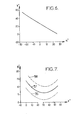
- FIG. 6 represents the variation curve of the pitch ⁇ of the sleeve 18 in function of the angle ⁇ of rotation of the reference 26 as identified in Figure 4.
- This kinematic law corresponds to a substantially linear decrease in the pitch ⁇ of the sleeve 18 when the angle of rotation ⁇ of the reference 26 increases.
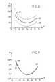
- the corresponding curves 39, 40 and 41 also substantially in U, represent the evolution of the instantaneous K bond Ki for different cyclic beat values (+ 11 °, 0 °, - 11 °) depending on the step y of the sleeve 18.
- These curves 39, 40 and 41 of evolution of the instantaneous K bond are clearly distinct from each other in FIG. 8.
- the pitch control device of the invention which is well compatible with a "gimbal" type rotor, rigid in drag, and with 4 or more blades, therefore copes well with the significant cyclical beat and the range of very large collective pitch control encountered on rotors tilting of convertible aircraft, and has the advantage of controlling the displacement of the pitch lever 20 of each blade around the axis X-X of pitch change of the corresponding blade using a connecting rod 21 slightly inclined on any radial plane with respect to the Z-Z axis of the rotor mast, and whose slope by relation to this plane can be chosen to correspond to the desired K connection for the rotor, and in this case a value K connection weakly negative for a rotor with zero eccentricity, as is the case of the rotor described above with reference to Figures 2 and 3, and in accordance with the requirement on the K link for the tilting rotors of convertible aircraft.
Landscapes
- Engineering & Computer Science (AREA)
- Aviation & Aerospace Engineering (AREA)
- Mechanical Engineering (AREA)
- Chemical & Material Sciences (AREA)
- Combustion & Propulsion (AREA)
- Transmission Devices (AREA)
- Toys (AREA)
Abstract
Description
- un mât rotor, destiné à être entraíné en rotation par sa base autour de son axe longitudinal,
- un moyeu, entraíné en rotation par le mât, et relié à ce dernier par des moyens de basculement, permettant un basculement d'ensemble du moyeu autour de tout axe de battement passant par l'axe du mât et perpendiculaire à ce dernier, et
- au moins deux pales, dont chacune est reliée au moyeu par des moyens de retenue et d'articulation de ladite pale en pas autour de son axe longitudinal de changement de pas, qui s'étend dans un plan de rotation du rotor, est un dispositif de commande de pas qui est externe au moyeu et, selon l'invention, se caractérise en ce qu'il comprend, pour chaque pale du rotor :
- un levier de pas, solidaire en rotation du pied de ladite pale autour dudit axe de changement de pas, et en saillie du côté du plan de rotation du rotor qui est dirigé vers la base du mât,
- une bielle de commande de pas, déplaçable dans une direction sensiblement parallèle à l'axe de rotation du mât,
- un renvoi, monté pivotant, autour d'un axe de pivot sensiblement contenu dans un plan radial par rapport à l'axe de rotation du mât, sur un point fixe d'un entraíneur, solidaire en rotation du mât, ladite bielle de commande de pas étant articulée sur ledit renvoi, au moins à pivotement autour d'un axe sensiblement parallèle à l'axe de pivot du renvoi sur l'entraíneur, et en un point décalé radialement vers l'extérieur dudit axe de pivot par rapport à l'axe de rotation du mât, et
- une bielle de liaison, articulée au moins à pivotement par une extrémité sur ledit levier de pas, autour d'un axe sensiblement parallèle audit axe de changement de pas, et, par son autre extrémité, sur le renvoi, en un point fixe de ce dernier situé entre ledit plan de rotation du rotor et le point d'articulation du renvoi sur l'entraíneur, de sorte que ladite bielle de liaison est faiblement inclinée sur tout plan radial par rapport à l'axe de rotation du mât, et que le renvoi convertit tout déplacement de ladite bielle de commande de pas en déplacement de ladite bielle de liaison dans une direction sensiblement transversale à la direction de l'axe du mât.
- la figure 1 est une vue schématique, en élévation latérale, d'un aéronef convertible à rotors basculants destinés à être équipés de dispositifs de commande de pas des pales selon l'invention,
- la figure 2 est une vue en perspective de côté et de dessus de la tête d'un rotor quadripale pour l'aéronef convertible de la figure 1, et équipé d'un dispositif de commande de pas selon l'invention, associé à un moyeu à plateau en étoile à quatre bras et de type « gimbal »,
- la figure 3 est une vue schématique en élévation latérale, selon l'axe de changement de pas d'une pale, de la tête de rotor de la figure 2,
- la figure 4 est un schéma de l'agencement cinématique du dispositif de commande de pas de la tête de rotor des figures 1 et 2, vu dans la même direction que la figure 3, avec indication des paramètres géométriques pris en compte pour calculer la longueur de la bielle de liaison, son inclinaison sur un plan radial par rapport à l'axe du mât et la liaison K correspondante,
- la figure 5 est un schéma illustrant la position, dans le plan défini par les axes du mât rotor et de changement de pas d'une pale, du point d'articulation de la bielle de liaison sur le levier de pas correspondant par rapport à l'axe de battement, et
- les figures 6 et 7 à 9 sont des courbes représentant respectivement la loi cinématique du pas du manchon de pale en fonction de la rotation du renvoi (figure 6), et les évolutions de l'inclinaison de la bielle (figure 7), de la liaison K instantanée (figure 8), et de la liaison K cyclique (figure 9), pour différentes valeurs de battement cyclique en fonction du pas collectif d'un manchon de pale, pour un rotor quadripale.

Claims (11)
- Dispositif de commande du pas des pales d'un rotor (4) d'aéronef convertible (1), pour un rotor (4) comportant :le dispositif de commande de pas étant externe au moyeu (8) et caractérisé en ce qu'il comprend, pour chaque pale du rotor :un mât rotor (7), destiné à être entraíné en rotation par sa base (7a) autour de son axe longitudinal (Z-Z),un moyeu (8), entraíné en rotation par le mât (7), et relié à ce dernier par des moyens (9) de basculement permettant un basculement d'ensemble du moyeu (8) autour de tout axe de battement passant par l'axe (Z-Z) du mât (7) et perpendiculaire à l'axe du mât,au moins deux pales, dont chacune est reliée au moyeu (8) par des moyens (16, 17) de retenue et d'articulation de ladite pale en pas autour de son axe (X-X) longitudinal de changement de pas, qui s'étend dans un plan de rotation du rotor (4),un levier de pas (20), solidaire en rotation du pied de ladite pale autour dudit axe (X-X) de changement de pas, et en saillie du côté du plan de rotation du rotor qui est dirigé vers la base (7a) du mât (7),une bielle (31) de commande de pas, déplaçable dans une direction sensiblement parallèle à l'axe (Z-Z) de rotation du mât (7),un renvoi (26), monté pivotant, autour d'un axe de pivot (28) sensiblement contenu dans un plan radial par rapport à l'axe (Z-Z) de rotation du mât (7), sur un point fixe d'un entraíneur (29), solidaire en rotation du mât (7), ladite bielle (31) de commande de pas étant articulée sur ledit renvoi (26), au moins à pivotement autour d'un axe (33) sensiblement parallèle à l'axe de pivot (28) du renvoi (26) sur l'entraíneur (29), et en un point décalé radialement vers l'extérieur dudit axe de pivot (28) par rapport à l'axe (Z-Z) de rotation du mât (7), etune bielle de liaison (21), articulée au moins à pivotement par une extrémité sur ledit levier de pas (20), autour d'un axe (22) sensiblement parallèle audit axe (X-X) de changement de pas, et, par son autre extrémité, sur le renvoi (26), en un point fixe (24) de ce dernier situé entre ledit plan de rotation du rotor et le point (35) d'articulation du renvoi (26) sur l'entraíneur (29) , de sorte que ladite bielle de liaison (21) est faiblement inclinée sur tout plan radial par rapport à l'axe (Z-Z) de rotation du mât (7), et que le renvoi (26) convertit tout déplacement de la bielle (31) de commande de pas en déplacement de la bielle de liaison (21) dans une direction sensiblement transversale à la direction de l'axe (Z-Z) du mât (7).
- Dispositif de commande selon la revendication 1, caractérisé en ce que ladite bielle de liaison (21) reste sensiblement parallèle à ou faiblement inclinée sur tout plan radial par rapport à l'axe (Z-Z) de rotation du mât (7) lorsque ladite pale effectue des débattements angulaires dans sa plage de pas.
- Dispositif de commande selon la revendication 1, caractérisé en ce que l'inclinaison de ladite bielle de liaison (21) sur tout plan radial par rapport à l'axe (Z-Z) du mât (7) correspond à une liaison pas-battement (liaison K) souhaitée pour la pale correspondante.
- Dispositif de commande selon la revendication 1, caractérisé en ce que l'angle d'inclinaison de ladite bielle de liaison (21) sur tout plan radial, perpendiculaire à l'axe (Z-Z) du mât (7), varie de sorte à procurer un couplage pas-battement (liaison K) selon une loi déterminée en fonction de l'angle de pas de la pale, lorsque cette dernière effectue des débattements angulaires en battement.
- Dispositif de commande selon l'une quelconque des revendications 1 à 4, caractérisé en ce que le renvoi (26) est sensiblement en forme de L, articulé par son coude (30) sur la bielle (31) de commande de pas, par l'extrémité de l'un (27) de ses bras (25, 27) sur l'entraíneur (26), et par l'extrémité de son autre bras (25) sur la bielle de liaison (21).
- Dispositif de commande selon l'une quelconque des revendications 1 à 5, caractérisé en ce que les axes de pivot (28, 33, 23) du renvoi (26) respectivement sur l'entraíneur (29), sur la bielle (31) de commande de pas, et sur la bielle (21) de liaison, sont sensiblement parallèles entre eux, ainsi qu'à l'axe de changement de pas (X-X) de la pale correspondante, en position neutre du moyeu (8).
- Dispositif de commande selon la revendication 6, caractérisé en ce que ledit renvoi (26) et ladite bielle de liaison (21) se déplacent sensiblement dans un plan parallèle à l'axe (Z-Z) du mât (7) et perpendiculaire à l'axe (28) de pivot du renvoi (26) sur l'entraíneur (29) et sensiblement perpendiculaire à l'axe (X-X) de changement de pas de la pale correspondante.
- Dispositif de commande selon l'une quelconque des revendications 1 à 7, caractérisé en ce que ledit levier de pas (20) est en saillie vers la base (7a) du mât (7) sur l'extrémité radiale interne, par rapport à l'axe (Z-Z) du mât (7), d'un manchon (18) de pale, rigide en torsion et lié en torsion au pied de la pale correspondante autour de l'axe (X-X) de changement de pas, et entourant lesdits moyens (16, 17) de retenue et d'articulation en pas de la pale.
- Dispositif de commande selon l'une quelconque des revendications 1 à 8, caractérisé en ce que ledit renvoi (26) est monté pivotant dans une chape (35) en saillie vers l'extérieur sur l'entraíneur (29).
- Dispositif de commande selon l'une quelconque des revendications 1 à 9, caractérisé en ce que ladite bielle de liaison (21) est articulée sur ledit levier de pas (20) et sur ledit renvoi (26) par des liaisons rotulées et/ou ledit renvoi (26) est articulé à ladite bielle de commande de pas (31) par une liaison rotulée.
- Aéronef convertible (1) comprenant au moins un rotor (4) basculant, destiné à basculer entre une configuration avion, dans laquelle le rotor (4) fonctionne comme une hélice d'avion, et une configuration hélicoptère, dans laquelle le rotor (4) fonctionne comme un rotor principal sustentateur d'hélicoptère, ledit rotor (4) comportantcaractérisé en ce que ledit dispositif de commande de pas est un dispositif selon l'une quelconque des revendications 1 à 10.un mât rotor (7), destiné à être entraíné en rotation par sa base (7a) autour de son axe longitudinal (Z-Z),un moyeu (8), entraíné en rotation par le mât (7), et relié à ce dernier par des moyens (9) de basculement permettant un basculement d'ensemble du moyeu (8) autour de tout axe de battement passant par l'axe (Z-Z) du mât (7) et perpendiculaire à l'axe du mât,au moins deux pales, dont chacune est reliée au moyeu (8) par des moyens (16, 17) de retenue et d'articulation de ladite pale en pas autour de son axe (X-X) longitudinal de changement de pas, qui s'étend dans un plan de rotation du rotor (4), etun dispositif de commande de pas, externe au moyeu (8),
Applications Claiming Priority (2)
| Application Number | Priority Date | Filing Date | Title |
|---|---|---|---|
| FR0204006 | 2002-03-29 | ||
| FR0204006A FR2837785B1 (fr) | 2002-03-29 | 2002-03-29 | Dispositif de commande du pas des pales d'un rotor d'aeronef convertible |
Publications (2)
| Publication Number | Publication Date |
|---|---|
| EP1348624A1 true EP1348624A1 (fr) | 2003-10-01 |
| EP1348624B1 EP1348624B1 (fr) | 2004-12-29 |
Family
ID=27799294
Family Applications (1)
| Application Number | Title | Priority Date | Filing Date |
|---|---|---|---|
| EP03290738A Expired - Lifetime EP1348624B1 (fr) | 2002-03-29 | 2003-03-24 | Dispositif de commande du pas des pales d'un rotor d'aéronef convertible |
Country Status (3)
| Country | Link |
|---|---|
| US (1) | US6824096B2 (fr) |
| EP (1) | EP1348624B1 (fr) |
| FR (1) | FR2837785B1 (fr) |
Families Citing this family (20)
| Publication number | Priority date | Publication date | Assignee | Title |
|---|---|---|---|---|
| RU2288134C1 (ru) * | 2005-03-30 | 2006-11-27 | Открытое акционерное общество Таганрогский авиационный научно-технический комплекс им. Г.М. Бериева | Механизм включения в проводку управления летательным аппаратом функционального устройства |
| US7780409B2 (en) * | 2005-09-30 | 2010-08-24 | The Boeing Company | Rotor apparatus and methods for vertical lift aircraft |
| US7740450B2 (en) * | 2005-11-23 | 2010-06-22 | General Electric Company | Lightweight hub for rotors |
| MX2008014460A (es) * | 2006-05-12 | 2009-04-30 | Textron Innovations Inc | Horquilla con encastres de brazos ranurados. |
| US8287237B2 (en) | 2006-12-08 | 2012-10-16 | Textron Innovations Inc. | Step-over blade-pitch control system |
| FR2946317B1 (fr) * | 2009-06-04 | 2011-06-17 | Eurocopter France | Guignol a rapport variable pour chaine de commande de vol manuelle d'aeronef a voiture tournante |
| US9365288B2 (en) | 2012-11-15 | 2016-06-14 | Textron Innovations Inc. | Blade-pitch control system with indexing swashplate |
| US9315265B2 (en) * | 2013-07-29 | 2016-04-19 | Sikorsky Aircraft Corporation | Adjustable scissor control link |
| US9701403B2 (en) * | 2014-02-18 | 2017-07-11 | Bell Helicopter Textron Inc. | Broad goods composite yoke for rotor system |
| US10336447B2 (en) * | 2014-12-02 | 2019-07-02 | Bell Helicopter Textron Inc. | Folding proprotor gimbal lock and blade lock mechanism |
| US11235858B2 (en) | 2014-12-02 | 2022-02-01 | Textron Innovations Inc. | Blade fold mechanism |
| US20170341733A1 (en) * | 2016-05-27 | 2017-11-30 | Sikorsky Aircraft Corporation | Rotor head for prop-rotor |
| US11325697B1 (en) * | 2016-07-18 | 2022-05-10 | Franklin Y. K. Chen | VTOL flying wing and flying wing aircraft |
| KR101849246B1 (ko) * | 2016-11-28 | 2018-04-16 | 한국항공우주연구원 | 틸트프롭 항공기 |
| EP3505443B1 (fr) * | 2017-12-27 | 2020-03-11 | LEONARDO S.p.A. | Avion convertible et son procédé de commande |
| CN109263868A (zh) * | 2018-09-28 | 2019-01-25 | 上海歌尔泰克机器人有限公司 | 一种无人机旋翼结构以及无人机飞行器 |
| US11560224B2 (en) * | 2020-01-09 | 2023-01-24 | Lockheed Martin Corporation | Eccentrically adjusted rotating scissor pitch control link |
| US11834164B2 (en) * | 2020-05-18 | 2023-12-05 | Iqinetics Technologies Inc. | Pulse-induced cyclic control lift propeller |
| CN112265635B (zh) * | 2020-11-10 | 2025-03-18 | 埃游科技(深圳)有限公司 | 一种旋翼倾转机构及无人机 |
| US12060148B2 (en) | 2022-08-16 | 2024-08-13 | Honeywell International Inc. | Ground resonance detection and warning system and method |
Citations (5)
| Publication number | Priority date | Publication date | Assignee | Title |
|---|---|---|---|---|
| US2971584A (en) * | 1957-02-25 | 1961-02-14 | Vyzk A Zkusebni Letecky Ustav | Devices for stabilising helicopter aircraft |
| FR1565217A (fr) * | 1967-05-09 | 1969-04-25 | ||
| FR2791319A1 (fr) | 1999-03-25 | 2000-09-29 | Eurocopter France | Aeronef convertible a rotors basculants |
| FR2791634A1 (fr) | 1999-03-30 | 2000-10-06 | Eurocopter France | Perfectionnements aux aeronefs convertibles a rotors basculants |
| FR2798359A1 (fr) | 1999-09-14 | 2001-03-16 | Eurocopter France | Perfectionnements aux aeronefs convertibles a rotors basculants |
Family Cites Families (5)
| Publication number | Priority date | Publication date | Assignee | Title |
|---|---|---|---|---|
| US2428200A (en) * | 1942-08-07 | 1947-09-30 | Autogiro Co Of America | Pitch control for aircraft sustaining rotors |
| US2620888A (en) * | 1947-03-10 | 1952-12-09 | Harold T Avery | Blade tracking mechanism for lifting rotors |
| FR2725689B1 (fr) * | 1994-10-13 | 1996-12-27 | Eurocopter France | Dispositif de commande du pas des pales d'un rotor de giravion |
| FR2768997B1 (fr) * | 1997-09-30 | 1999-12-03 | Eurocopter France | Dispositif a plateaux cycliques de commande du pas des pales d'un rotor avec piste et doigt d'arret du plateau non tournant |
| IT1308395B1 (it) * | 1999-02-26 | 2001-12-17 | Finmeccanica Spa | Dispositivo di controllo dei passi ciclico e collettivo per un rotoredi un elicottero. |
-
2002
- 2002-03-29 FR FR0204006A patent/FR2837785B1/fr not_active Expired - Fee Related
-
2003
- 2003-03-20 US US10/392,645 patent/US6824096B2/en not_active Expired - Fee Related
- 2003-03-24 EP EP03290738A patent/EP1348624B1/fr not_active Expired - Lifetime
Patent Citations (5)
| Publication number | Priority date | Publication date | Assignee | Title |
|---|---|---|---|---|
| US2971584A (en) * | 1957-02-25 | 1961-02-14 | Vyzk A Zkusebni Letecky Ustav | Devices for stabilising helicopter aircraft |
| FR1565217A (fr) * | 1967-05-09 | 1969-04-25 | ||
| FR2791319A1 (fr) | 1999-03-25 | 2000-09-29 | Eurocopter France | Aeronef convertible a rotors basculants |
| FR2791634A1 (fr) | 1999-03-30 | 2000-10-06 | Eurocopter France | Perfectionnements aux aeronefs convertibles a rotors basculants |
| FR2798359A1 (fr) | 1999-09-14 | 2001-03-16 | Eurocopter France | Perfectionnements aux aeronefs convertibles a rotors basculants |
Also Published As
| Publication number | Publication date |
|---|---|
| US6824096B2 (en) | 2004-11-30 |
| FR2837785A1 (fr) | 2003-10-03 |
| US20030183722A1 (en) | 2003-10-02 |
| FR2837785B1 (fr) | 2004-12-03 |
| EP1348624B1 (fr) | 2004-12-29 |
Similar Documents
| Publication | Publication Date | Title |
|---|---|---|
| EP1348624B1 (fr) | Dispositif de commande du pas des pales d'un rotor d'aéronef convertible | |
| EP1346910B1 (fr) | Rotor de giravion a entraînement homocinétique | |
| EP0254605B1 (fr) | Dispositif directionnel et stabilisateur à rotor anti-couple caréné et incliné et à empennage en "V" dissymétrique, et hélicoptère équipé d'un tel dispositif | |
| EP0870676B1 (fr) | Dispositif de commande individuelle des pales de rotors de voilures tournantes d'aéronefs avec plateaux cycliques multiples | |
| FR2768997A1 (fr) | Dispositif a plateaux cycliques de commande du pas des pales d'un rotor avec piste et doigt d'arret du plateau non tournant | |
| FR2837784A1 (fr) | Rotor de giravion a entrainement homocinetique avec differentiel de partage de couple | |
| EP4041628B1 (fr) | Système de commande de calage cyclique de pales | |
| EP0680876A1 (fr) | Rotor anti-couple caréné à pales flottantes | |
| EP0706937B1 (fr) | Dispositif de commande du pas des pales d'un rotor de giravion | |
| FR2768996A1 (fr) | Dispositif a plateaux cycliques de commande du pas des pales d'un rotor avec entraineur de plateau tournant | |
| FR2943621A1 (fr) | Pale munie d'un amortisseur de trainee et rotor muni d'une telle pale | |
| EP0706938A1 (fr) | Dispositif de commande de pas des pales d'un rotor de giravion | |
| EP0742144B1 (fr) | Rotor avec dispositif d'amortissement de trainée des pales | |
| EP0457646B1 (fr) | Dispositif à plateaux cycliques montés sur articulations découplées en tangage et roulis, pour la commande du pas des pales d'un rotor de giravion | |
| FR3006294A3 (fr) | Aeronef a voilure tournante et a soufflante canalisee appartenant aux categories des mini et micro drones | |
| FR2931132A1 (fr) | Systeme de commande assiste d'un giravon | |
| BE1023550B1 (fr) | Systeme de plateau cyclique pour rotor d'helicoptere | |
| FR2770828A1 (fr) | Dispositif a plateaux cycliques de commande du pas des pales d'un rotor avec plateau non-tournant articule sur une rotule centrale | |
| FR2770827A1 (fr) | Dispositif a plateaux cycliques de commande du pas des pales d'un rotor avec plateau non-tournant articule par clavettes sur une rotule centrale | |
| EP0402236B1 (fr) | Dispositif de butées escamotables pour pales de rotors de giravions, et tête de rotor le comportant | |
| EP2217492A2 (fr) | Plateau cyclique sur rotors | |
| FR2569388A1 (fr) | Dispositif d'actionnement monte sur un moyeu pour la commande collective du pas des pales d'un rotor | |
| CA3059098A1 (fr) | Systeme carene et aeronef | |
| EP0718188B1 (fr) | Rotor sans articulation à anneaux intermédiaires de commande de pas | |
| FR3042474A1 (fr) | Combinateur des commandes vol en lacet et de poussee pour un helicoptere hybride |
Legal Events
| Date | Code | Title | Description |
|---|---|---|---|
| PUAI | Public reference made under article 153(3) epc to a published international application that has entered the european phase |
Free format text: ORIGINAL CODE: 0009012 |
|
| AK | Designated contracting states |
Kind code of ref document: A1 Designated state(s): AT BE BG CH CY CZ DE DK EE ES FI FR GB GR HU IE IT LI LU MC NL PT RO SE SI SK TR |
|
| AX | Request for extension of the european patent |
Extension state: AL LT LV MK |
|
| GRAP | Despatch of communication of intention to grant a patent |
Free format text: ORIGINAL CODE: EPIDOSNIGR1 |
|
| 17P | Request for examination filed |
Effective date: 20040114 |
|
| AKX | Designation fees paid |
Designated state(s): GB IT |
|
| GRAS | Grant fee paid |
Free format text: ORIGINAL CODE: EPIDOSNIGR3 |
|
| REG | Reference to a national code |
Ref country code: DE Ref legal event code: 8566 |
|
| GRAA | (expected) grant |
Free format text: ORIGINAL CODE: 0009210 |
|
| AK | Designated contracting states |
Kind code of ref document: B1 Designated state(s): GB IT |
|
| REG | Reference to a national code |
Ref country code: GB Ref legal event code: FG4D Free format text: NOT ENGLISH |
|
| REG | Reference to a national code |
Ref country code: IE Ref legal event code: FG4D Free format text: FRENCH |
|
| GBT | Gb: translation of ep patent filed (gb section 77(6)(a)/1977) |
Effective date: 20050419 |
|
| RIN2 | Information on inventor provided after grant (corrected) |
Inventor name: RAMPAL, ETIENNE Inventor name: ZOPPITELLI, ELIO Inventor name: CORNILLE, ERIC |
|
| PLBE | No opposition filed within time limit |
Free format text: ORIGINAL CODE: 0009261 |
|
| STAA | Information on the status of an ep patent application or granted ep patent |
Free format text: STATUS: NO OPPOSITION FILED WITHIN TIME LIMIT |
|
| 26N | No opposition filed |
Effective date: 20050930 |
|
| PGFP | Annual fee paid to national office [announced via postgrant information from national office to epo] |
Ref country code: GB Payment date: 20140226 Year of fee payment: 12 |
|
| PGFP | Annual fee paid to national office [announced via postgrant information from national office to epo] |
Ref country code: IT Payment date: 20150225 Year of fee payment: 13 |
|
| GBPC | Gb: european patent ceased through non-payment of renewal fee |
Effective date: 20150324 |
|
| PG25 | Lapsed in a contracting state [announced via postgrant information from national office to epo] |
Ref country code: GB Free format text: LAPSE BECAUSE OF NON-PAYMENT OF DUE FEES Effective date: 20150324 |
|
| PG25 | Lapsed in a contracting state [announced via postgrant information from national office to epo] |
Ref country code: IT Free format text: LAPSE BECAUSE OF NON-PAYMENT OF DUE FEES Effective date: 20160324 |