EP1348510A1 - Process for disassembling a brazed structure, for example an open-face honeycomb structure - Google Patents
Process for disassembling a brazed structure, for example an open-face honeycomb structure Download PDFInfo
- Publication number
- EP1348510A1 EP1348510A1 EP03251899A EP03251899A EP1348510A1 EP 1348510 A1 EP1348510 A1 EP 1348510A1 EP 03251899 A EP03251899 A EP 03251899A EP 03251899 A EP03251899 A EP 03251899A EP 1348510 A1 EP1348510 A1 EP 1348510A1
- Authority
- EP
- European Patent Office
- Prior art keywords
- process according
- metal
- transport material
- wire
- brazing alloy
- Prior art date
- Legal status (The legal status is an assumption and is not a legal conclusion. Google has not performed a legal analysis and makes no representation as to the accuracy of the status listed.)
- Granted
Links
Images

Classifications
-
- B—PERFORMING OPERATIONS; TRANSPORTING
- B23—MACHINE TOOLS; METAL-WORKING NOT OTHERWISE PROVIDED FOR
- B23K—SOLDERING OR UNSOLDERING; WELDING; CLADDING OR PLATING BY SOLDERING OR WELDING; CUTTING BY APPLYING HEAT LOCALLY, e.g. FLAME CUTTING; WORKING BY LASER BEAM
- B23K1/00—Soldering, e.g. brazing, or unsoldering
- B23K1/0008—Soldering, e.g. brazing, or unsoldering specially adapted for particular articles or work
- B23K1/0014—Brazing of honeycomb sandwich structures
-
- B—PERFORMING OPERATIONS; TRANSPORTING
- B23—MACHINE TOOLS; METAL-WORKING NOT OTHERWISE PROVIDED FOR
- B23K—SOLDERING OR UNSOLDERING; WELDING; CLADDING OR PLATING BY SOLDERING OR WELDING; CUTTING BY APPLYING HEAT LOCALLY, e.g. FLAME CUTTING; WORKING BY LASER BEAM
- B23K1/00—Soldering, e.g. brazing, or unsoldering
- B23K1/018—Unsoldering; Removal of melted solder or other residues
-
- F—MECHANICAL ENGINEERING; LIGHTING; HEATING; WEAPONS; BLASTING
- F01—MACHINES OR ENGINES IN GENERAL; ENGINE PLANTS IN GENERAL; STEAM ENGINES
- F01D—NON-POSITIVE DISPLACEMENT MACHINES OR ENGINES, e.g. STEAM TURBINES
- F01D11/00—Preventing or minimising internal leakage of working-fluid, e.g. between stages
- F01D11/08—Preventing or minimising internal leakage of working-fluid, e.g. between stages for sealing space between rotor blade tips and stator
- F01D11/12—Preventing or minimising internal leakage of working-fluid, e.g. between stages for sealing space between rotor blade tips and stator using a rubstrip, e.g. erodible. deformable or resiliently-biased part
- F01D11/127—Preventing or minimising internal leakage of working-fluid, e.g. between stages for sealing space between rotor blade tips and stator using a rubstrip, e.g. erodible. deformable or resiliently-biased part with a deformable or crushable structure, e.g. honeycomb
-
- B—PERFORMING OPERATIONS; TRANSPORTING
- B23—MACHINE TOOLS; METAL-WORKING NOT OTHERWISE PROVIDED FOR
- B23K—SOLDERING OR UNSOLDERING; WELDING; CLADDING OR PLATING BY SOLDERING OR WELDING; CUTTING BY APPLYING HEAT LOCALLY, e.g. FLAME CUTTING; WORKING BY LASER BEAM
- B23K2101/00—Articles made by soldering, welding or cutting
- B23K2101/02—Honeycomb structures
-
- F—MECHANICAL ENGINEERING; LIGHTING; HEATING; WEAPONS; BLASTING
- F05—INDEXING SCHEMES RELATING TO ENGINES OR PUMPS IN VARIOUS SUBCLASSES OF CLASSES F01-F04
- F05D—INDEXING SCHEME FOR ASPECTS RELATING TO NON-POSITIVE-DISPLACEMENT MACHINES OR ENGINES, GAS-TURBINES OR JET-PROPULSION PLANTS
- F05D2230/00—Manufacture
- F05D2230/20—Manufacture essentially without removing material
- F05D2230/23—Manufacture essentially without removing material by permanently joining parts together
- F05D2230/232—Manufacture essentially without removing material by permanently joining parts together by welding
- F05D2230/237—Brazing
-
- F—MECHANICAL ENGINEERING; LIGHTING; HEATING; WEAPONS; BLASTING
- F05—INDEXING SCHEMES RELATING TO ENGINES OR PUMPS IN VARIOUS SUBCLASSES OF CLASSES F01-F04
- F05D—INDEXING SCHEME FOR ASPECTS RELATING TO NON-POSITIVE-DISPLACEMENT MACHINES OR ENGINES, GAS-TURBINES OR JET-PROPULSION PLANTS
- F05D2230/00—Manufacture
- F05D2230/70—Disassembly methods
-
- F—MECHANICAL ENGINEERING; LIGHTING; HEATING; WEAPONS; BLASTING
- F05—INDEXING SCHEMES RELATING TO ENGINES OR PUMPS IN VARIOUS SUBCLASSES OF CLASSES F01-F04
- F05D—INDEXING SCHEME FOR ASPECTS RELATING TO NON-POSITIVE-DISPLACEMENT MACHINES OR ENGINES, GAS-TURBINES OR JET-PROPULSION PLANTS
- F05D2230/00—Manufacture
- F05D2230/80—Repairing, retrofitting or upgrading methods
-
- F—MECHANICAL ENGINEERING; LIGHTING; HEATING; WEAPONS; BLASTING
- F05—INDEXING SCHEMES RELATING TO ENGINES OR PUMPS IN VARIOUS SUBCLASSES OF CLASSES F01-F04
- F05D—INDEXING SCHEME FOR ASPECTS RELATING TO NON-POSITIVE-DISPLACEMENT MACHINES OR ENGINES, GAS-TURBINES OR JET-PROPULSION PLANTS
- F05D2250/00—Geometry
- F05D2250/20—Three-dimensional
- F05D2250/28—Three-dimensional patterned
- F05D2250/283—Three-dimensional patterned honeycomb
Definitions
- the present invention is drawn to a process for disassembling a brazed structure and, more particularly, a brazed structure comprising a hollow component having a closure component bonded thereto by a metallic brazing alloy for closing off an end of the hollow component.
- Brazing processes are known in the prior art for forming a metallic bond between two metal surfaces.
- Aircraft gas turbine engines rely heavily on a number of brazing processes.
- open-face honeycomb structures, or air seals are brazed for use in high temperature heat-resistance applications on lightweight aircraft engines.
- the unique characteristic of such air seal structures is that the core structure provides an effective seal for a stream of hot gas.
- U.S. Patent 5,439,637 and 5,871,139 disclose processes for removing metallic brazing alloys from brazed joints by packing the joints with metallic powders and the like.
- a brazed structure for example open face honeycomb structures which are static parts and act as sealing surfaces in jet engines
- a metallic brazing alloy for closing off an end of the at least one hollow element wherein the at least one hollow element and closure component define an open faced cell.
- the process of the present invention comprises the steps of locating in the cell a wire transport material, covering the open faced cell with a metal wire fiber material which penetrates the cell and contacts the wire transport material, and heating the hollow component to sufficient temperature wherein the metallic brazing alloy flows through the wire transport material and onto the metal wire fiber material.
- the wire transport material comprises a packing of metal wires of various shapes and sizes which form capillary passages at the interstitial locations between the wires.
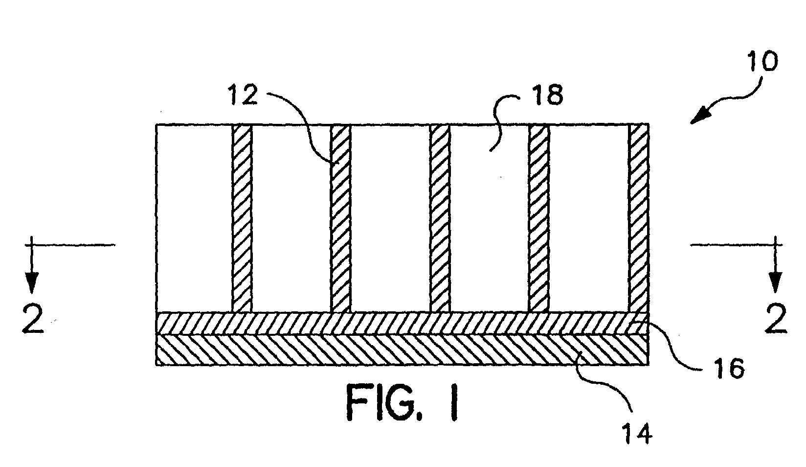
- a brazed structure 10 includes an open-faced honeycomb structure or component 12 and a closure component 14 which are bonded together by a metallic brazing alloy 16 to define a plurality of cells 18.
- the cells 18 are packed with a wire transport material 20.
- the wire transport material fills the cells and may slightly overflow the cells.
- wire transport material means a packing of metal wires of various sizes and shapes which form capillary passages at the interstitial locations between the wires.
- the wire transport material comprises a metal material having a melting temperature greater than that of the metallic brazing alloy 16 used to bond the honeycomb structure 12 to the closure component 14.
- the wire transport material 20 must also be wettable by the metallic brazing alloy.
- the wire transport material may be formed of a metal selected from the group consisting of aluminum, cobalt, copper, iron, nickel, their alloys, carbon steel, stainless steel and mixtures thereof.
- the wire transport material is formed of metal wires of various shapes and sizes.
- the metal wires have diameters of between 0.005" (0.13 mm) to 0.050" (1.3 mm), a length of up to 0.500" (12.7 mm) and an interstice of between 0.0001" (0.0025 mm) to 0.015" (0.038 mm).
- the metal has a diameter of between 0.010" (0.25 mm) to 0.030" (0.76 mm), a length of up to 0.500" (12.7 mm) and an interstice of between 0.001" (0.025 mm) to 0.007" (0.18 mm).
- the interstice or spacing is such that it acts as a capillary passageway for the liquid brazing alloy as will be discussed hereinbelow.
- the metal wire fiber material 22 Located on top of the cell or honeycomb structure 12 is a metal wire fiber material 22 which contacts the wire transport material 20.
- the metal wire fiber material 22, preferably, comprises a commercial grade steel wool material of between #0000 and #4.
- the steel wool material has a diameter of between 0.0006" (0.15 mm) to 0.008" (0.20 mm).
- the wire transport material 20 creates a differential pressure between the bottom of the cell (the metallic brazing alloy 16) and the metal wire fiber material 22 wherein the differential pressure is between 2.5 psia (17.2 kPa) to 12.6 psia (87.9 kPa). The purpose of the differential pressure will be explained with reference to the process as set forth hereinbelow.
- the process of the present invention comprises the steps of: locating in a cell a wire transport material, covering the cell with a metal wire fiber material which contacts the wire transport material, heating the cell to sufficient temperature wherein the metallic brazing alloy flows through interstice of the wire transport material and onto the metal wire fiber material where the liquid brazing alloy is solidify.
- the components are thereafter separated and the metal wire fiber material with the solidified brazing alloy can be removed (either before or after separation of the component parts).
- the process of the present invention is preferably performed in an inert, hydrogen or vacuum furnace atmosphere in order to reduce oxidation and promoting wetting of the wire transport material by the liquid brazing alloy.
- the debrazing temperature is not substantially higher than the original brazing temperature and is normally between 25-50°F (14-28°C) above the original brazing temperature. Temperatures significantly higher can alter the metallurgical structural properties of the component parts and adversely affect the mechanical properties. It has been found that the total cycle time is generally between 10-30 minutes at the debrazing temperature.
- the preferred materials for the wire transport material are carbon and stainless steel wire.
- the wire transport material is packed into the cell to form interstices of between 0.001" (0.025 mm) to 0.015" (0.38 mm), preferably 0.001" (0.0025 mm) to 0.007" (0.18 mm). These interstices act as capillary passageways and are filled in seconds upon melting of the metallic brazing alloy.
- the metallic brazing alloy flows upward as a result of capillary action.
- the metal transport material which creates a differential pressure between the cell at the brazing alloy and the wire fiber material above the cells helps draw the liquid brazing alloy onto the metal wire fiber material (by providing a wicking affect) where the brazing material is solidified.
- the brazing material is then removed from the hollow component by simply removing the metal wire fiber material. Upon removal of sufficient amounts of the brazing material, the component parts may be disassembled.
- a fifth stage low pressure, outer air seal honeycomb segment of a PW 4000 jet engine was selected as a candidate component to utilize the thermal brazing process of the present invention.
- a set of 20 engine run parts were cleaned per UAL GN/MM 4-0-06 process 2N.
- the air seal segment parent material was AMS5536
- the honeycomb was made of Hastelloy X
- the braze metal was AMS4777.
- honeycomb cells of the segment were filled with 510 grams of cut wire.
- the cut wire was made of carbon steel of 0.014-inch (0.36 mm) nominal diameter that conformed to AMS2431/3.
- Honeycomb cells were filled to the top with some allowed overflow. Specific preparation attention was focused on the edges of the segment to insure peripheral cells were filled. Loose cut wire was removed from all non-honeycomb regions to prevent unwanted flow locations.
- the cut wire fill area was sprayed with a standard braze powder binder and allowed to dry for 45 minutes. The air seals were inverted and checked to insure cut wire did not fall out. Three commercially available pads of #0000 steel wool were placed (lengthwise) on top of cells containing the cut wire. All cells were covered with steel wool and overhang was trimmed.
- the air seal segments were placed in a vacuum furnace with honeycomb face down. Strips of fiber frax cloth were cut to dimension (10 inch (254 mm) length and 3-1/2 inch (89 mm) wide)) and placed over the air seal. Fiber frax cloth is used to keep liquid braze metal from flowing in unwanted regions. Another air seal, containing cut wire and steel wool, was placed on top followed by another sheet of fiber frax cloth. Four stacks of five air seals (separated by cloth) were placed in the furnace. Weights were placed on top of the sandwich stacks to ensure equal pressure on steel wool.
- the furnace cycle began by evacuating chamber to 0.56-micron vacuum.
- the load was heated to 1800°F (982°C) ⁇ 25°F (14°C) and held for 10 minutes. Heating rate was 30°F/min.
- the load was then heated to 1950°F (1065°C) ⁇ 25°F (14°C) at 20°F/min (11°C/mm) and held for 30 minutes.
- the load was cooled to 1800°F (982°C) ⁇ 25°F (14°C) at 15°F/min and then quench cooled to 300°F (149°C) .
- Honeycomb, cut wire and steel wool with the brazing alloy was easily removed from the air seal segment with pneumatic and hand chisel. The component parts were than separated.
Landscapes
- Engineering & Computer Science (AREA)
- Mechanical Engineering (AREA)
- General Engineering & Computer Science (AREA)
- Filtering Materials (AREA)
- Separation Using Semi-Permeable Membranes (AREA)
Abstract
Description
- The present invention is drawn to a process for disassembling a brazed structure and, more particularly, a brazed structure comprising a hollow component having a closure component bonded thereto by a metallic brazing alloy for closing off an end of the hollow component.
- Brazing processes are known in the prior art for forming a metallic bond between two metal surfaces. Aircraft gas turbine engines rely heavily on a number of brazing processes. For example, open-face honeycomb structures, or air seals, are brazed for use in high temperature heat-resistance applications on lightweight aircraft engines. The unique characteristic of such air seal structures is that the core structure provides an effective seal for a stream of hot gas.
- Several methods are known in the prior art for chemically separating brazed components. These approaches utilize leaching and stripping solutions. These methods are generally difficult to control and often lead to damage to the base metal. Such methods are disclosed, for example, in U.S. Patents 4,274,908, 4,302,246, and 4,324,626.
- U.S. Patent 5,439,637 and 5,871,139 disclose processes for removing metallic brazing alloys from brazed joints by packing the joints with metallic powders and the like.
- Naturally, it would be highly desirable to provide a process for removing metallic brazing alloy from honeycomb structures as defined above without the requirement of chemical acid stripping and the like.
- The foregoing object is achieved by way of the present invention which provides a process for disassembling a brazed structure (for example open face honeycomb structures which are static parts and act as sealing surfaces in jet engines) comprising a hollow component having at least one hollow element and closure component bonded thereto by a metallic brazing alloy for closing off an end of the at least one hollow element wherein the at least one hollow element and closure component define an open faced cell. The process of the present invention comprises the steps of locating in the cell a wire transport material, covering the open faced cell with a metal wire fiber material which penetrates the cell and contacts the wire transport material, and heating the hollow component to sufficient temperature wherein the metallic brazing alloy flows through the wire transport material and onto the metal wire fiber material. In a preferred embodiment, the wire transport material comprises a packing of metal wires of various shapes and sizes which form capillary passages at the interstitial locations between the wires.
- Further features and advantages of the present invention will appear hereinbelow.
-
- Figure 1 is a partial sectional side view of an open-face honeycomb brazed structure which may be disassembled in accordance with the process of the present invention.
- Figure 2 is a partial top view of the open-face honeycomb structure of Figure 1.
- Figure 3 is a view similar to Figure 1 showing the open-face honeycomb structure loaded with the wire transport material and metal wire fiber material in accordance with the process of the present invention.
-
- With reference to Figures 1 and 2, a brazed
structure 10 includes an open-faced honeycomb structure orcomponent 12 and aclosure component 14 which are bonded together by a metallic brazingalloy 16 to define a plurality ofcells 18. - With reference to Figure 3, the
cells 18 are packed with awire transport material 20. The wire transport material fills the cells and may slightly overflow the cells. As used in the instant specification, wire transport material means a packing of metal wires of various sizes and shapes which form capillary passages at the interstitial locations between the wires. The wire transport material comprises a metal material having a melting temperature greater than that of the metallic brazingalloy 16 used to bond thehoneycomb structure 12 to theclosure component 14. Thewire transport material 20 must also be wettable by the metallic brazing alloy. In accordance with the present invention, the wire transport material may be formed of a metal selected from the group consisting of aluminum, cobalt, copper, iron, nickel, their alloys, carbon steel, stainless steel and mixtures thereof. Particularly suitable metals include stainless steels and carbon steels. As noted above, the wire transport material is formed of metal wires of various shapes and sizes. The metal wires have diameters of between 0.005" (0.13 mm) to 0.050" (1.3 mm), a length of up to 0.500" (12.7 mm) and an interstice of between 0.0001" (0.0025 mm) to 0.015" (0.038 mm). In the preferred embodiment, the metal has a diameter of between 0.010" (0.25 mm) to 0.030" (0.76 mm), a length of up to 0.500" (12.7 mm) and an interstice of between 0.001" (0.025 mm) to 0.007" (0.18 mm). The interstice or spacing is such that it acts as a capillary passageway for the liquid brazing alloy as will be discussed hereinbelow. Located on top of the cell orhoneycomb structure 12 is a metalwire fiber material 22 which contacts thewire transport material 20. The metalwire fiber material 22, preferably, comprises a commercial grade steel wool material of between #0000 and #4. The steel wool material has a diameter of between 0.0006" (0.15 mm) to 0.008" (0.20 mm). Thewire transport material 20 creates a differential pressure between the bottom of the cell (the metallic brazing alloy 16) and the metalwire fiber material 22 wherein the differential pressure is between 2.5 psia (17.2 kPa) to 12.6 psia (87.9 kPa). The purpose of the differential pressure will be explained with reference to the process as set forth hereinbelow. - The process of the present invention comprises the steps of: locating in a cell a wire transport material, covering the cell with a metal wire fiber material which contacts the wire transport material, heating the cell to sufficient temperature wherein the metallic brazing alloy flows through interstice of the wire transport material and onto the metal wire fiber material where the liquid brazing alloy is solidify. The components are thereafter separated and the metal wire fiber material with the solidified brazing alloy can be removed (either before or after separation of the component parts).
- The process of the present invention is preferably performed in an inert, hydrogen or vacuum furnace atmosphere in order to reduce oxidation and promoting wetting of the wire transport material by the liquid brazing alloy. Generally, the debrazing temperature is not substantially higher than the original brazing temperature and is normally between 25-50°F (14-28°C) above the original brazing temperature. Temperatures significantly higher can alter the metallurgical structural properties of the component parts and adversely affect the mechanical properties. It has been found that the total cycle time is generally between 10-30 minutes at the debrazing temperature.
- The preferred materials for the wire transport material are carbon and stainless steel wire. As noted above, the wire transport material is packed into the cell to form interstices of between 0.001" (0.025 mm) to 0.015" (0.38 mm), preferably 0.001" (0.0025 mm) to 0.007" (0.18 mm). These interstices act as capillary passageways and are filled in seconds upon melting of the metallic brazing alloy. The metallic brazing alloy flows upward as a result of capillary action. The metal transport material which creates a differential pressure between the cell at the brazing alloy and the wire fiber material above the cells helps draw the liquid brazing alloy onto the metal wire fiber material (by providing a wicking affect) where the brazing material is solidified. The brazing material is then removed from the hollow component by simply removing the metal wire fiber material. Upon removal of sufficient amounts of the brazing material, the component parts may be disassembled.
- The preferred embodiment will be further described with reference to the following example.
- A fifth stage low pressure, outer air seal honeycomb segment of a PW 4000 jet engine was selected as a candidate component to utilize the thermal brazing process of the present invention. A set of 20 engine run parts were cleaned per UAL GN/MM 4-0-06 process 2N. The air seal segment parent material was AMS5536, the honeycomb was made of Hastelloy X and the braze metal was AMS4777.
- The honeycomb cells of the segment were filled with 510 grams of cut wire. The cut wire was made of carbon steel of 0.014-inch (0.36 mm) nominal diameter that conformed to AMS2431/3. Honeycomb cells were filled to the top with some allowed overflow. Specific preparation attention was focused on the edges of the segment to insure peripheral cells were filled. Loose cut wire was removed from all non-honeycomb regions to prevent unwanted flow locations.
- The cut wire fill area was sprayed with a standard braze powder binder and allowed to dry for 45 minutes. The air seals were inverted and checked to insure cut wire did not fall out. Three commercially available pads of #0000 steel wool were placed (lengthwise) on top of cells containing the cut wire. All cells were covered with steel wool and overhang was trimmed.
- The air seal segments, with steel wool attached, were placed in a vacuum furnace with honeycomb face down. Strips of fiber frax cloth were cut to dimension (10 inch (254 mm) length and 3-1/2 inch (89 mm) wide)) and placed over the air seal. Fiber frax cloth is used to keep liquid braze metal from flowing in unwanted regions. Another air seal, containing cut wire and steel wool, was placed on top followed by another sheet of fiber frax cloth. Four stacks of five air seals (separated by cloth) were placed in the furnace. Weights were placed on top of the sandwich stacks to ensure equal pressure on steel wool.
- The furnace cycle began by evacuating chamber to 0.56-micron vacuum. The load was heated to 1800°F (982°C) ± 25°F (14°C) and held for 10 minutes. Heating rate was 30°F/min. The load was then heated to 1950°F (1065°C) ± 25°F (14°C) at 20°F/min (11°C/mm) and held for 30 minutes. The load was cooled to 1800°F (982°C) ± 25°F (14°C) at 15°F/min and then quench cooled to 300°F (149°C) .
- Honeycomb, cut wire and steel wool with the brazing alloy was easily removed from the air seal segment with pneumatic and hand chisel. The component parts were than separated.
- It is to be understood that the invention is not limited to the illustrations described and shown herein, which are deemed to be merely illustrative of the best modes of carrying out the invention, and which are susceptible of modification of form, size, arrangement of parts and details of operation. The invention rather is intended to encompass all such modifications which are within its scope as defined by the claims.
Claims (14)
- A process for disassembling a brazed structure (10) comprising a hollow component having at least one hollow element (12) and a closure component (14) bonded thereto by a metallic brazing alloy (16) for closing off an end of the at least one hollow element so as to define therewith an open faced cell (18), comprising the steps of:(a) locating in the cell (18) a wire transport material (20);(b) covering the open faced cell (18) with a metal wire fiber material (22) which penetrates the cell and contacts the wire transport material;(c) heating the hollow component (12) to sufficient temperature wherein the metallic brazing alloy (16) flows through the wire transport material (20) and onto the metal wire fiber material (22); and(d) separating the hollow component (12) from the closure component (14).
- A process according to claim 1, wherein the hollow component (12) comprises a honeycomb structure having a plurality of hollow elements.
- A process according to claim 2, wherein the closure component (14) closes off an end of a plurality of the hollow elements (18) of the honeycomb structure (12).
- A process according to any preceding claim, wherein the metallic brazing alloy (16) solidifies on the metal wire fiber material (22).
- A process according to claim 4, wherein metal wire fiber material (22) with the solidified metallic brazing alloy (18) is removed from the hollow component (10).
- A process according to any preceding claim, wherein the wire transport material (20) comprises a metal material having a melting temperature greater than that of the metallic brazing alloy (16) and is wettable by the metallic brazing alloy(16).
- A process according to claim 6, wherein wire transport material (20) is a metal material selected from the group consisting of aluminum, cobalt, copper, iron, nickel, their alloys, carbon steel, stainless steel and mixtures thereof.
- A process according to claim 6, wherein the wire transport material (20) is selected from the group consisting of carbon steel, stainless steel and mixtures thereof.
- A process according to any preceding claim, wherein the wire transport material (20) comprises a metal having a diameter of between 0.005" (0.127 mm) to 0.050" (1.27 mm), a length of up to 0.500" (12.7 mm) and an interstice of between 0.0001" (0.0025 mm) to 0.015" (0.0381 mm).
- A process according to any of claims 1 to 8, wherein the wire transport material (20) comprises a metal having a diameter of between 0.010" (0.254 mm) to 0.030" (0.762 mm), a length of up to 0.500" (12.7mm) and an interstice of between 0.001" (0.0254 mm) to 0.007" (0.1776 mm).
- A process according to any preceding claim, wherein the metal wire fiber material (22) comprises a commercial grade steel wool material.
- A process according to claim 11, wherein the commercial grade is between #0000 and #4.
- A process according to claim 11, wherein the steel wool material has a diameter of between 0.0006" (0.015 mm) to 0.008" (0.203 mm).
- A process according to any preceding claim, wherein the metal transport material (20) creates a differential pressure between the brazing alloy (16) and the metal wire fiber material (22) of between 2.5 psia (17 kPa) to 12.6 psia (87 kPa).
Applications Claiming Priority (2)
| Application Number | Priority Date | Filing Date | Title |
|---|---|---|---|
| US107231 | 1987-10-09 | ||
| US10/107,231 US6655576B2 (en) | 2002-03-26 | 2002-03-26 | Process for disassembling a brazed structure |
Publications (2)
| Publication Number | Publication Date |
|---|---|
| EP1348510A1 true EP1348510A1 (en) | 2003-10-01 |
| EP1348510B1 EP1348510B1 (en) | 2005-05-25 |
Family
ID=27804363
Family Applications (1)
| Application Number | Title | Priority Date | Filing Date |
|---|---|---|---|
| EP03251899A Expired - Lifetime EP1348510B1 (en) | 2002-03-26 | 2003-03-26 | Process for disassembling a brazed structure, for example an open-face honeycomb structure |
Country Status (6)
| Country | Link |
|---|---|
| US (1) | US6655576B2 (en) |
| EP (1) | EP1348510B1 (en) |
| JP (1) | JP3685787B2 (en) |
| DE (1) | DE60300695T2 (en) |
| MX (1) | MXPA03002402A (en) |
| SG (1) | SG107644A1 (en) |
Families Citing this family (3)
| Publication number | Priority date | Publication date | Assignee | Title |
|---|---|---|---|---|
| US20090286102A1 (en) * | 2008-05-15 | 2009-11-19 | Tubine Overhaul Services Pte Ltd. | Induced capillary action brazing using metallic foam matrix |
| EP2308628A1 (en) * | 2009-10-06 | 2011-04-13 | Siemens Aktiengesellschaft | Method of removal of a soldered component with local heating of the soldered place |
| US10362720B2 (en) | 2014-08-06 | 2019-07-23 | Greene Lyon Group, Inc. | Rotational removal of electronic chips and other components from printed wire boards using liquid heat media |
Citations (5)
| Publication number | Priority date | Publication date | Assignee | Title |
|---|---|---|---|---|
| US4164606A (en) * | 1977-11-08 | 1979-08-14 | Ernst Spirig | Tinned copper braids for solder removing |
| US4324626A (en) * | 1979-11-13 | 1982-04-13 | United Technologies Corporation | Selective removal of nickel-based braze alloy from nickel-based metals |
| US5871139A (en) * | 1994-07-20 | 1999-02-16 | Praxair S.T. Technology, Inc. | Debrazing of structures with a powdered wicking agent |
| JP2000151093A (en) * | 1998-11-13 | 2000-05-30 | Nec Corp | Method for removing semiconductor package |
| US6251494B1 (en) * | 1998-06-24 | 2001-06-26 | Rolls-Royce Deutschland Ltd & Co Kg | Honeycomb structure seal for a gas turbine and method of making same |
Family Cites Families (8)
| Publication number | Priority date | Publication date | Assignee | Title |
|---|---|---|---|---|
| US4274908A (en) | 1978-08-15 | 1981-06-23 | United Technologies Corporation | Cyanide free solution and process for removing gold-nickel braze |
| US4293089A (en) * | 1979-05-08 | 1981-10-06 | The United States Of America As Represented By The United States Department Of Energy | Brazing method |
| US4302246A (en) | 1980-01-03 | 1981-11-24 | Enthone, Incorporated | Solution and method for selectively stripping alloys containing nickel with gold, phosphorous or chromium from stainless steel and related nickel base alloys |
| EP0124563B1 (en) * | 1982-11-12 | 1988-01-20 | Adnovum Ag | Dewatering process, procedure and device |
| US5305941A (en) * | 1992-12-28 | 1994-04-26 | Plato Products, Inc. | Desoldering wick |
| US5439637A (en) | 1994-07-20 | 1995-08-08 | Pyromet Group, Inc. | Debrazing of structures with a powdered wicking agent |
| US5901898A (en) * | 1997-05-14 | 1999-05-11 | Easy-Braid Company | System for removing solder |
| US6186387B1 (en) * | 1999-04-12 | 2001-02-13 | Pace Incorporated | Solder collecting capsule and solder extracting desoldering tool using same |
-
2002
- 2002-03-26 US US10/107,231 patent/US6655576B2/en not_active Expired - Lifetime
-
2003
- 2003-03-19 MX MXPA03002402A patent/MXPA03002402A/en active IP Right Grant
- 2003-03-24 SG SG200301421A patent/SG107644A1/en unknown
- 2003-03-25 JP JP2003083199A patent/JP3685787B2/en not_active Expired - Fee Related
- 2003-03-26 DE DE60300695T patent/DE60300695T2/en not_active Expired - Lifetime
- 2003-03-26 EP EP03251899A patent/EP1348510B1/en not_active Expired - Lifetime
Patent Citations (5)
| Publication number | Priority date | Publication date | Assignee | Title |
|---|---|---|---|---|
| US4164606A (en) * | 1977-11-08 | 1979-08-14 | Ernst Spirig | Tinned copper braids for solder removing |
| US4324626A (en) * | 1979-11-13 | 1982-04-13 | United Technologies Corporation | Selective removal of nickel-based braze alloy from nickel-based metals |
| US5871139A (en) * | 1994-07-20 | 1999-02-16 | Praxair S.T. Technology, Inc. | Debrazing of structures with a powdered wicking agent |
| US6251494B1 (en) * | 1998-06-24 | 2001-06-26 | Rolls-Royce Deutschland Ltd & Co Kg | Honeycomb structure seal for a gas turbine and method of making same |
| JP2000151093A (en) * | 1998-11-13 | 2000-05-30 | Nec Corp | Method for removing semiconductor package |
Non-Patent Citations (1)
| Title |
|---|
| PATENT ABSTRACTS OF JAPAN vol. 2000, no. 08 6 October 2000 (2000-10-06) * |
Also Published As
| Publication number | Publication date |
|---|---|
| MXPA03002402A (en) | 2004-08-11 |
| EP1348510B1 (en) | 2005-05-25 |
| DE60300695T2 (en) | 2005-10-20 |
| JP3685787B2 (en) | 2005-08-24 |
| SG107644A1 (en) | 2004-12-29 |
| US6655576B2 (en) | 2003-12-02 |
| US20030183678A1 (en) | 2003-10-02 |
| DE60300695D1 (en) | 2005-06-30 |
| JP2003285158A (en) | 2003-10-07 |
Similar Documents
| Publication | Publication Date | Title |
|---|---|---|
| US4485961A (en) | Welding by hot isostatic pressing (HIP) | |
| US5156321A (en) | Powder metallurgy repair technique | |
| US4283822A (en) | Method of fabricating composite nozzles for water cooled gas turbines | |
| US4183456A (en) | Method of fabricating liquid cooled gas turbine components | |
| US4929511A (en) | Low temperature aluminum based brazing alloys | |
| US7658315B2 (en) | Process of brazing superalloy components | |
| EP1348510B1 (en) | Process for disassembling a brazed structure, for example an open-face honeycomb structure | |
| JPH0440099B2 (en) | ||
| JP2634678B2 (en) | Sputtering target assembly and method of manufacturing the same | |
| JPS58128292A (en) | Thin strip of phosphorus copper brazing filler metal | |
| US5135156A (en) | Method of producing nickel-alloy honeycomb panels | |
| US5871139A (en) | Debrazing of structures with a powdered wicking agent | |
| US5439637A (en) | Debrazing of structures with a powdered wicking agent | |
| US4029254A (en) | Method of diffusion bonding and brazing of materials | |
| US4838341A (en) | Production of low temperature aluminum based brazing alloys | |
| JPS5868489A (en) | Bodies to be joined and joining method for said bodies | |
| JPS6046889A (en) | Production of multi-layered roll | |
| US7377419B1 (en) | Brazing open cell reticulated copper foam to stainless steel tubing with vacuum furnace brazed gold/indium alloy plating | |
| US3807030A (en) | Method of preparing oxidation resistant materials | |
| CA1101644A (en) | Method of fabricating liquid cooled gas turbine components | |
| JP3626553B2 (en) | Manufacturing method of clad material of copper alloy and steel | |
| JPH0147278B2 (en) | ||
| JPH0216185B2 (en) | ||
| JPH06218557A (en) | Production of honeycomb | |
| JPS6418559A (en) | Integrating method for different kinds of metal |
Legal Events
| Date | Code | Title | Description |
|---|---|---|---|
| PUAI | Public reference made under article 153(3) epc to a published international application that has entered the european phase |
Free format text: ORIGINAL CODE: 0009012 |
|
| AK | Designated contracting states |
Kind code of ref document: A1 Designated state(s): AT BE BG CH CY CZ DE DK EE ES FI FR GB GR HU IE IT LI LU MC NL PT RO SE SI SK TR |
|
| AX | Request for extension of the european patent |
Extension state: AL LT LV MK |
|
| 17P | Request for examination filed |
Effective date: 20040316 |
|
| AKX | Designation fees paid |
Designated state(s): CH DE FR GB LI |
|
| GRAP | Despatch of communication of intention to grant a patent |
Free format text: ORIGINAL CODE: EPIDOSNIGR1 |
|
| GRAS | Grant fee paid |
Free format text: ORIGINAL CODE: EPIDOSNIGR3 |
|
| GRAA | (expected) grant |
Free format text: ORIGINAL CODE: 0009210 |
|
| AK | Designated contracting states |
Kind code of ref document: B1 Designated state(s): CH DE FR GB LI |
|
| REG | Reference to a national code |
Ref country code: GB Ref legal event code: FG4D |
|
| REG | Reference to a national code |
Ref country code: CH Ref legal event code: EP |
|
| REG | Reference to a national code |
Ref country code: IE Ref legal event code: FG4D |
|
| REF | Corresponds to: |
Ref document number: 60300695 Country of ref document: DE Date of ref document: 20050630 Kind code of ref document: P |
|
| ET | Fr: translation filed | ||
| PLBE | No opposition filed within time limit |
Free format text: ORIGINAL CODE: 0009261 |
|
| STAA | Information on the status of an ep patent application or granted ep patent |
Free format text: STATUS: NO OPPOSITION FILED WITHIN TIME LIMIT |
|
| 26N | No opposition filed |
Effective date: 20060228 |
|
| REG | Reference to a national code |
Ref country code: CH Ref legal event code: NV Representative=s name: E. BLUM & CO. AG PATENT- UND MARKENANWAELTE VSP |
|
| PGFP | Annual fee paid to national office [announced via postgrant information from national office to epo] |
Ref country code: FR Payment date: 20100324 Year of fee payment: 8 |
|
| REG | Reference to a national code |
Ref country code: FR Ref legal event code: ST Effective date: 20111130 |
|
| PG25 | Lapsed in a contracting state [announced via postgrant information from national office to epo] |
Ref country code: FR Free format text: LAPSE BECAUSE OF NON-PAYMENT OF DUE FEES Effective date: 20110331 |
|
| PGFP | Annual fee paid to national office [announced via postgrant information from national office to epo] |
Ref country code: DE Payment date: 20130320 Year of fee payment: 11 Ref country code: GB Payment date: 20130320 Year of fee payment: 11 Ref country code: CH Payment date: 20130312 Year of fee payment: 11 |
|
| REG | Reference to a national code |
Ref country code: DE Ref legal event code: R119 Ref document number: 60300695 Country of ref document: DE |
|
| REG | Reference to a national code |
Ref country code: CH Ref legal event code: PL |
|
| GBPC | Gb: european patent ceased through non-payment of renewal fee |
Effective date: 20140326 |
|
| REG | Reference to a national code |
Ref country code: DE Ref legal event code: R119 Ref document number: 60300695 Country of ref document: DE Effective date: 20141001 |
|
| PG25 | Lapsed in a contracting state [announced via postgrant information from national office to epo] |
Ref country code: LI Free format text: LAPSE BECAUSE OF NON-PAYMENT OF DUE FEES Effective date: 20140331 Ref country code: DE Free format text: LAPSE BECAUSE OF NON-PAYMENT OF DUE FEES Effective date: 20141001 Ref country code: GB Free format text: LAPSE BECAUSE OF NON-PAYMENT OF DUE FEES Effective date: 20140326 Ref country code: CH Free format text: LAPSE BECAUSE OF NON-PAYMENT OF DUE FEES Effective date: 20140331 |