EP1348503A1 - Molten steel feeder for continuous casting, and method for continuous casting using the molten steel feeder - Google Patents
Molten steel feeder for continuous casting, and method for continuous casting using the molten steel feeder Download PDFInfo
- Publication number
- EP1348503A1 EP1348503A1 EP01272322A EP01272322A EP1348503A1 EP 1348503 A1 EP1348503 A1 EP 1348503A1 EP 01272322 A EP01272322 A EP 01272322A EP 01272322 A EP01272322 A EP 01272322A EP 1348503 A1 EP1348503 A1 EP 1348503A1
- Authority
- EP
- European Patent Office
- Prior art keywords
- molten steel
- electrode
- immersion nozzle
- tundish
- supplying
- Prior art date
- Legal status (The legal status is an assumption and is not a legal conclusion. Google has not performed a legal analysis and makes no representation as to the accuracy of the status listed.)
- Granted
Links
Images

Classifications
-
- B—PERFORMING OPERATIONS; TRANSPORTING
- B22—CASTING; POWDER METALLURGY
- B22D—CASTING OF METALS; CASTING OF OTHER SUBSTANCES BY THE SAME PROCESSES OR DEVICES
- B22D11/00—Continuous casting of metals, i.e. casting in indefinite lengths
- B22D11/10—Supplying or treating molten metal
-
- B—PERFORMING OPERATIONS; TRANSPORTING
- B22—CASTING; POWDER METALLURGY
- B22D—CASTING OF METALS; CASTING OF OTHER SUBSTANCES BY THE SAME PROCESSES OR DEVICES
- B22D41/00—Casting melt-holding vessels, e.g. ladles, tundishes, cups or the like
- B22D41/50—Pouring-nozzles
-
- B—PERFORMING OPERATIONS; TRANSPORTING
- B22—CASTING; POWDER METALLURGY
- B22D—CASTING OF METALS; CASTING OF OTHER SUBSTANCES BY THE SAME PROCESSES OR DEVICES
- B22D41/00—Casting melt-holding vessels, e.g. ladles, tundishes, cups or the like
- B22D41/50—Pouring-nozzles
- B22D41/60—Pouring-nozzles with heating or cooling means
Definitions
- the present invention relates to an apparatus for supplying molten steel used for the continuous casting, and also to a method for continuously casting with the apparatus for supplying molten steel, which is useful to prevent an immersion nozzle clogging and to reduce slab surface defects.
- a continuous casting method in which molten steel stored in a tundish is supplied to a top of a mold via an immersion nozzle disposed at the lower part of the tundish to form a solidified shell in the mold, and then the slab is continuously produced by withdrawing the solidified shell from a bottom of the mold.
- the mold flux and Al oxide or the like entrapped in the molten steel are trapped by the solidified shell in the mold, thus slab surface defects such as powder defect and/or slag spot are liable to occur.
- the defects on the slab surface cause surface defects in the products, when the slab having the slab surface defects is hot-rolled.
- a method for purging an inert gas into molten steel passing through an immersion nozzle in order to avoid the nozzle clogging has been known ("Tetsu To Hagane", vol. 66, S868, Iron and Steel Institute of Japan), and various methods for preventing nozzle clogging, which are applicable to the casting, have recently been proposed.
- a method for purging an inert gas into molten steel passing through an immersion nozzle is proposed in Japanese Patent Application Laid-open No. H4-319055, in which case, the amount (liter (Nl)/min) of the inert gas to be blown into the molten steel is adjusted in accordance with the throughput (t/min) of the molten steel passing through the immersion nozzle.
- the resulting electromagnetic force applied to the molten steel promotes bubbles of the purged inert gas to remove form the refractory material for the purging gas, and thereby to reduce the size of generated gas bubbles.
- the size of the gas bubbles, which are trapped by the solidified shell in the mold is reduced, thereby enabling the defects due to the gas bubbles in the slab to prevent on the surface of products, which are manufactured by hot-rolling the slab.
- the present inventors focused on the electrical capillarity and then developed a method for preventing the Al oxide or the like in the molten steel from being deposited on the inner surface of an immersion nozzle by utilizing the electrical capillarity.
- the electrical capillarity described herein implies a phenomenon in which the interfacial tension between an ion solution and an electrode immersed therein can be changed by the potential applied to the electrode.
- the present inventors carefully investigated the phenomenon and succeeded in finding the following features [1] to [7]:
- the present invention is completed on the basis of the above-mentioned features and it is characterized by an apparatus for supplying molten steel defined by the following structural arrangement (1) or (2) as well as by a continuous casting method defined by the following structural arrangements (3) to (7):
- the material for producing the immersion nozzle and the like is selected from refractory materials having a good electrical conductivity at a temperature not less than the melting point of steel. This is due to the necessity of flowing the electrical current between the refractory material and the molten steel.
- the expression "a material having a good electrical conductivity at a temperature not less than the melting point of steel” will be sometimes abbreviated by an expression "a material having a good electrical conductivity”.
- the refractory materials disposed in the tundish, as well as the refractory materials included in the upper nozzle, the gate for controlling the amount of the molten steel to be supplied into the mold, the immersion nozzle and the like are normally preheated by the combustion gas, before starting the continuous casting by supplying the molten steel into the tundish.
- the surface temperature of these refractory materials at the end of preheating should be typically 800 to 1,300°C.
- the target temperature on the surface of the refractory materials after preheating depends on the casting work conditions, such as the capacity of the tundish, the time between the start of supplying the molten steel into the tundish and the start of supplying the molten steel into the mold, and others.
- the electric circuit between the paired electrodes at the end of preheating in the state of the molten steel being not yet supplied to the tundish includes the refractory materials disposed in the tundish, the refractory materials constituting the upper nozzle, the gate and the immersion nozzle, and a steel structure for supporting these refractory materials.
- the electrical resistance of the refractory materials and the steel structure normally decrease with the increase of the temperature.
- the expression "the electrical resistance between the one electrode and the other electrode in the end of preheating” implies an electrical resistance between the one electrode and the other electrode in an electrical circuit, which may be constituted by refractory elements in a tundish heated at a target surface temperature, refractory such as upper nozzle, a gate and an immersion nozzle, and a steel construction for supporting these refractory materials, so that it implies the electrical resistance minimized just before starting to supply the molten steel into the tundish.
- this electrical resistance will be sometimes denoted by "an initial electrical resistance”.
- the so-called hot tundish recycling in which the tundish is recycled without cooling, is employed.
- two methods can be applied; in the one method, the tundish is preheated, and in the other method, new molten steel is supplied into the tundish without preheating.
- the surface temperature of the refractory materials in the tundish is 1,000 to 1,400°C.
- the above-mentioned electrical resistance means the electrical resistance between the one electrode and the other electrode in an electric circuit which is constituted by the above-mentioned refractory materials and the steel structure at such a high temperature, and therefore it means the electrical resistance just before the molten steel is supplied to the tundish. In other words, it means the initial electrical resistance.
- the electrical resistance which is determined by the current and voltage between the one electrode and the other electrode during the time interval from the start to the end of casting means an electrical resistance between the one electrode and the other electrode in an electrical circuit of the molten steel supplied into the tundish. Such an electrical resistance in the electrical circuit of the molten steel increases with the increase of the casting time.
- this electrical resistance is denoted in some cases by “the electrical resistance during the casting”.
- An apparatus for supplying molten steel according to the present invention and a continuous casting method according to the present invention will be described as for the following items:
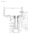
- FIG. 1 is a longitudinal sectional view schematically showing an embodiment of the apparatus for supplying molten steel according to the present invention.
- a three-layer type-sliding gate is shown as for a molten steel flow control mechanism.
- the present invention is not restricted to the sliding gate of this type. For instance, a double layer type sliding gate and/or a flow control mechanism using a stopper can be employed.
- the apparatus for supplying molten steel comprises a tundish 1 having an upper nozzle 2 at its bottom, a sliding gate 3 disposed beneath the upper nozzle 2, an immersion nozzle 4 connected to the sliding gate 3, one electrode 5 disposed at the sidewall of the tundish 1, the other electrode 6 disposed at the immersion nozzle 4 and a power supply 7 connected to both the one electrode 5 and the other electrode 6.
- the shape of the tundish 1 for receiving the molten steel 8 and the lining made of a refractory material are not for special use, but those for conventional use.
- the upper nozzle 2 disposed at the bottom of the tundish 1 is made of a refractory material, and has an exit hole 2a for supplying the molten steel 8 stored in the tundish 1 downwards.
- the sliding gate 3 has a three-layer structure comprising an upper plate 31, a lower plate 32 and a movable plate 33 disposed therebetween.
- the upper plate 31, the lower plate 32 and the movable plate 33 are made of a refractory material and each has a hole 31a, 32a or 33a.
- the flow rate of the molten steel 8 supplied downwards can be controlled by a horizontal displacement of the movable plate 33 actuated by a driving mechanism (not shown).
- the immersion nozzle 4 is equipped with two exit ports 4a at its lower position, and a part of the immersion nozzle 4 where the exit ports 4a are included, can be inserted into a mold 9.
- the shape of the immersion nozzle 4 is not restricted to that shown in Fig. 1.
- the one electrode 5 is disposed in such a manner that it pirces the sidewall of the tundish 1 and its one end reaches the inner space of the tundish 1.
- an end of the one electrode 5 is preferably immersed into the molten steel 8 in the state of operation.
- the surface area of the one electrode 5, which comes in contact with the molten steel 8 should be not less than 10 cm 2 .
- the material forming the one electrode 5 has a good electrical conductivity and a long time durability in the state in which it is in contact with the molten steel 8 in the tundish 1. Accordingly, the material can be selected from refractory materials, graphite, steel, high melting-point metal, such as molybdenum, tungsten or the like, or a composite material thereof.
- the installation of the one electrode 5 can be carried out according to one of the following methods, as shown in Fig. 1.
- a bore for the electrode is formed in iron shells of the sidewall of the tundish and a refractory material thereof, and then the electrode is inserted into the iron shell and the refractory material.
- the one electrode 5 is immersed into the molten steel 8 by inserting it directly from the top surface of the molten steel.
- a stopper is employed as a flow control mechanism for pouring the molten steel into the mold, the stopper is constituted by a refractory material having a good electrical conductivity and then the stopper itself can be used as one electrode 5.
- the upper nozzle or the sliding gate constituted by a refractory material having a good electrical conductivity can be used as one electrode 5.
- Each of these electrodes may provide a similar effect, so that the selection of one electrode can be carried out from viewpoint of the manufacturing cost and the ease in operation. If, however, the one electrode 5 is disposed in the mold, an electrical current occasionally flows via the outer surface of the immersion nozzle, thereby making it difficult to prevent the Al oxide or the like in the molten steel to be deposited onto the inner surface of the immersion nozzle. Accordingly, the one electrode 5 should not be disposed in the mold.
- the other electrode 6 Since the other electrode 6 is not in direct contact with the molten steel 8, a metal having the heat-resisting property up to approx. 1,200°C, or a material, such as PiB 2 , ZrB 2 , SiC, graphite or the like, can be used as a refractory material for the other electrode 6.
- a metal such as carbon steel, stainless steel, Ni or the like, has a better electrical conductivity, compared with the above refractory materials. However, it tends to react with carbon included in the immersion nozzle, and then it occasionally changes into a low melting-point material, hence arising a problem of material dissipation due to dissolving. Therefore, the electrode constituted by the refractory material is preferably employed when a heavy thermal charge will be applied thereto.
- the other electrode 6 has to be in contact with a part of an element constituted by a refractory material having a good electrical conductivity.
- the other electrode 6 shown in Fig. 1 has a cylindrical shape and embedded in the refractory material of the immersion nozzle 4, and is interposed between the upper end of the immersion nozzle 4 and a level slightly above the meniscus level in the mold 9. It is preferable that the other electrode 6 is disposed facing the whole inner surface of the immersion nozzle 4. However, if the other electrode 6 is disposed being below the meniscus level of the immersion nozzle 4, there is a possible danger that the material of the other electrode 6 melt according to the selected material. Hence, such an arrangement as shown in Fig. 1 is normally employed.
- the other electrode 6 approaches the molten steel 8 passing through the inner surface of the immersion nozzle 4 over almost the entire area of the immersion nozzle 4 with the substantially same distance therebetween in continuous casting.
- This structural arrangement enables to suppress the spatially partial drop of voltage, when the electrical current passes through the refractory material forming the immersion nozzle 4.
- the shape and arrangement of the other electrode 6 is not restricted to those shown in Fig. 1.
- the shape and arrangement shown in Figs. 2 to 4 can also be employed.
- the same refractory material as that for the one electrode 5 can be used for the material of the other electrode 6.
- Fig. 2 is a longitudinal sectional view of another embodiment, in which case, the other electrode 6 is embedded in the immersion nozzle 4.
- the other electrode 6a is a rod-shaped piece made of a conductive refractory material and is embedded in a small area of the immersion nozzle 4 from the outer surface thereof.
- the embedding can be realized by machining a hole in the immersion nozzle 4, either when or after it is produced by means of the press-sintering method.
- the electrode having such a simple structure provides no local electrical current and can be effectively operated over a wide range.
- the shape of the electrode 6a it is desirable that an end part thereof is parallel to the axis of the immersion nozzle 4 and can be embedded in the immersion nozzle 4.
- Fig. 3 is a plan view of another embodiment of an immersion nozzle, wherein the other electrode 6 is mounted onto the outer surface of the nozzle.
- the other electrode 6b comprises a wire-shaped or rod-shaped element and is wound around the outer surface of the immersion nozzle 4.
- the outer surface of the immersion nozzle 4 is coated by an antioxidant. Since the antioxidant has an electric insulation property, the antioxidant coated has to be removed, when the other electrode 6b is wound around the immersion nozzle 4.
- Fig. 4 is also a plan view of another embodiment of an immersion nozzle, wherein the other electrode 6 is mounted on the outer surface of the nozzle.
- the other electrode 6c comprises an annular metal element, which is equipped with clamp means at an opened part thereof.
- the clamp means is fastened by means of bolts and nuts after the other electrode 6c is mounted on the outer surface of the immersion nozzle 4.
- the antioxidant coated on the outer surface of the immersion nozzle 4 is also removed.
- the power supply 7 is connected with one electrode 5 and the other electrode 6 of the paired electrodes via lead wires 7a, and a power is supplied to the electrodes 5 and 6 in the case of operation.
- the immersion nozzle 4 is constituted by a refractory material having a good electrical conductivity
- the upper nozzle 2 and sliding gate 3, whose inner surfaces are in contact with the molten steel can be constituted by a refractory material having a good electrical conductivity.
- the element onto which the other electrode 6 is mounted i.e., regarding the immersion nozzle 4 in Fig. 1, the inner surface, with which the molten steel comes in contact, has to be formed by the refractory material having a good electrical conductivity.
- the other electrode 6 is mounted onto the immersion nozzle 4. This is due to the fact that Al oxide or the like is deposited most frequently on the inner surface of the immersion nozzle 4 during the continuous casting, and thus a current should be supplied between the molten steel passing through the immersion nozzle 4 and the inner surface of the immersion nozzle 4.
- the whole parts of the immersion nozzle 4 can be formed by a refractory material having a good electrical conductivity.
- the immersion nozzle 4 can be formed by employing more than double radial layers structure wherein the outer layer is constituted by a material having a high mechanical strength and the inner layer being in contact with the molten steel is constituted by a refractory material having a good electrical conductivity.
- a part of the inner layer or the outer layer can be constituted by a material such as high purity alumina or the like having a less electrical conductivity.
- the sliding gate 3 can be constituted by a refractory material having a good electrical conductivity and then the other electrode 6 can be mounted onto the sliding gate 3.
- more than two of the upper nozzle 2, the sliding gate 3 and the immersion nozzle 4 can also be constituted by refractory materials and then the other electrode 6 can be mounted onto each of them.
- the sliding gate 3 is constituted by a refractory material having a good electrical conductivity
- the movable plate 33 which has the narrowest flow channel and to which Al oxide or the like tents to deposit is constituted by the refractory material having a good electrical conductivity.
- the sliding gate 3 can also be constituted, as similar to the upper nozzle 2, by more than double radial layers structure, and the inner layer in contact with the molten steel is constituted by the refractory material having a good electrical conductivity.
- the sliding gate 3 and the immersion nozzle 4 is constituted by a refractory material and the other electrode 6 is mounted on it, it is preferable that the other electrode 6 is mounted onto the immersion nozzle 4.
- Such a structural arrangement is employed to supply an electrical current between the inner surface of the immersion nozzle 4 and the molten steel during the continuous casting, since Al oxide or the like deposited on the inner surface of the immersion nozzle 4 influences upon the stability of operation in the continuous casting and the quality of products.
- the refractory material having a good electrical conductivity it is preferable that the material has an electrical conductivity of not less than 1x10 2 S/m, and more preferably, 1x10 4 to 1x10 6 S/m at a temperature not less than the melting point of the molten steel 8 stored in the tundish.
- the refractory material having a good electrical conductivity can be selected from materials including graphite such as alumina graphite, zirconia graphite , magnesia graphite or the like as a main component, materials of solid electrolyte, materials of boride system, such as TiB 2 , ZrB 2 or the like. In the following, the properties of the respective materials will be described:
- the refractory material of alumina graphite which is frequently used in the immersion nozzle, contains 5 to 35 wt % graphite. Not less than 5 wt % graphite provides a good electrical conductivity over a wide range from the room temperature to a temperature at which the steel is molten. More preferably, not less than about 12 wt % graphite provides an electrical conductivity of not less than 1x 10 4 S/m.
- the graphite is included in a 5 to 20 wt % concentration.
- the graphite at a concentration of not less than 5 wt % provides a good electrical conductivity over a wide range from room temperature to the temperature at which the steel is molten. More preferably, more than about 10 wt % graphite provides an electrical conductivity of not less than 1x10 4 S/m.
- the graphite concentration of more than 20 wt % provides a problem in which the mechanical strength is reduced.
- the upper limit of the graphite concentration in the refractory material of zirconia graphite is smaller than that in the refractory material of alumina graphite. This is due to the fact that the density of zirconia is greater than that of alumina, thereby providing a greater change in the density of the refractory material itself, in which the graphite having a smaller density is included.
- a solid electrolyte has a good electrical conductivity at a temperature at which a steel is molten.
- the electrical conductivity is approximately 1x10 2 S/m at the melting point of the steel and therefore it is not sufficiently large.
- the usage of such a material provides a problem in which an electrical current flows in a short circuit and local partial currents arise, thereby making it difficult to prevent the alumina or the like to be deposited thereon over a wide area.
- the refractory material having an electrical conductivity of not less than 1x10 3 S/m should be used in the present invention.
- TiB 2 or ZrB 2 has an electrical conductivity of not less than 1x10 5 S/m, so that it can be employed as a refractory material for supplying a current to the steel.
- either the refractory material including graphite as a main component or the refractory material of boride system can be employed.
- a refractory material of boride system is expensive to manufacture, so that it is difficult to construct a large structure with the refractory material.
- the refractory material of boride system can be exclusively used in only a part of a channel for flowing the molten steel.
- the refractory material which is preferably used in the present invention, is the refractory material including graphite as a main component.
- the refractory material of alumina graphite should be used.
- an insulating element is interposed between one electrode 5 and an element on which the other electrode 6 is mounted, said element being one of the upper nozzle 2, the sliding gate 3 and the immersion nozzle 4, which are formed by a refractory material having a good electrical conductivity.
- one electrode 5 is disposed in the tundish 1 and the other electrode 6 is disposed in the immersion nozzle 4.
- the insulating element is interposed either between the tundish 1 and the one electrode 5, or between the tundish 1 and the upper nozzle 2, or between the upper nozzle 2 and the sliding gate 3, or between the sliding gate 3 and the immersion nozzle 4.
- This treatment makes it possible to suppress the formation of short circuits between the one electrode 5 and the immersion nozzle 4 in which the other electrode 6 is disposed, when an electrical current is supplied.
- another insulating element is further interposed between the immersion nozzle 4 in which the other electrode 6 is disposed and the sliding gate 3 adjacent thereto, the leak current to the sliding gate 3 can be further suppressed, thereby enabling the current to effectively be supplied to the molten steel.
- the initial electrical resistance between the one electrode 5 and the other electrode 6 in the tundish is set to be more than 500 ⁇ , either at the time at which the preheating of the tundish is ended before the molten steel is supplied to the tundish, or at the time before the molten steel is supplied to the tundish when the tundish which is once used for the casting is recycled without preheating. If the initial electrical resistance is less than 500 Q, no sufficient current sends into the molten steel passing through the inside of the immersion nozzle 4 during the casting and the current flows in a short circuit to elements other than the molten steel, thereby making it impossible to effectively prevent the deposition of the Al oxide or the like onto the inner surface of the immersion nozzle.
- a refractory material having a low electrical conductivity either between the tundish 1 and the one electrode 5, or between the upper nozzle 2 and the refractory material of the tundish 1 and/or the steel structure of the tundish, or between the sliding gate 3 and the steel structure of the tundish 1.
- an insulating sheet comprising glass fibers can also be inserted between the above-mentioned elements. It is useful to further interpose an insulating sheet between every two of the upper nozzle 2, the sliding gate 3 and the immersion nozzle 4, and between each of these elements and corresponding supporting element, and between adjacent layers in the case of the double layer structure.
- the other electrode 6 is disposed in the immersion nozzle 4 as a refractory material having a good electrical conductivity, and an electrical current is supplied between the immersion nozzle and the molten steel passing through the inside of the immersion nozzle
- it is preferable that either [1] between the tundish 1 and the one electrode 5 or [2] between the immersion nozzle and the gate 3 which is in contact with the immersion nozzle, and between the immersion nozzle and a holder for supporting the immersion nozzle on the sliding gate, or both the above [1] and [2] is/are electrically insulated from each other.
- the immersion nozzle 4 and the main body of the tundish 1, said main body comprising the refractory material lining and the steel structure can also be electrically insulated from each other.
- the other electrodes are disposed in the immersion nozzle 4 and the gate 3, which are constituted by a refractory material having a good electrical conductivity, and electrical currents are supplied respectively between the immersion nozzle 4 and the molten steel passing through the inside of the immersion nozzle and between the upper nozzle 2 and the molten steel
- the gate 3 and the upper nozzle 2 which are constituted by a refractory material having a good electrical conductivity, and an electrical current is supplied respectively between the molten steel passing through the inside of the immersion nozzle and the immersion nozzle 4, between the molten steel and the gate 3, and between the upper nozzle 2 and the molten steel, it is preferable that either [1] between the tundish 1 and the one electrode 5 or [2] between the steel sturcture of the tundish and each of the immersion nozzle, the gate and the upper nozzle, or both the above [1] and [2] is/are electrically insulated from each other.
- the mineral material used for insulation generally has an electrical resistance of not less than 1 ⁇ 10 5 ⁇ m at room temperature, thereby providing a sufficient insulating property.
- the ion conductivity takes place in most mineral materials at such a high temperature as those in the molten steel, so that the electrical resistance decreases.
- an insulating sheet comprising fibers of such an insulating refractory material, such as Al 2 O 3 , SiO 2 or the like, or a coating material including Al 2 O 3 , SiO 2 or the like can be employed.
- the insulating sheet is inserted and then clamped either between the immersion nozzle and the gate in contact therewith or between the immersion nozzle and the holder for supporting the immersion nozzle on the sliding gate, the holder being in contact with the immersion nozzle, to form a sandwich structure.
- the thickness of the sheet is preferably 1 to 4 mm.
- the thickness of the coating is preferably 0.2 to 1.0 mm, and alumina matter, silica matter or the like can be used for the adhesive.
- the upper limit of the initial electrical resistance is ideally infinite. However, it tends to be 1x10 8 ⁇ in an apparatus for supplying the molten steel from a tundish to a mold in actual continuous casting machine.
- the electrical resistance which is calculated from the current and voltage between the one electrode 5 and the other electrode 6 during the period from the start to the end of casting is less than 1/10 of the initial electrical resistance between the one electrode and the other electrode in the tundish, either at the end of preheating of the tundish before the molten steel is supplied, or at the time before the molten steel is supplied to the tundish in the case in which the tundish is recycled without preheating.
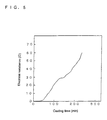
- Fig. 5 is a diagram showing the change in the electrical resistance between one electrode and the other electrode during the casting.
- the change is exemplified in the case of the initial electrical resistance of 0.7 ⁇ .
- the resistance of the circuit in which an electrical current flows in the molten steel passing through the inside of the immersion nozzle, normally increases.
- the surface of the refractory material which has a good electrical conductivity and disposed in the immersion nozzle, said surface being in contact with the molten steel, changes in quality as time passed and/or non-conductive materials, such as alumina or the like, are deposited on the surface.
- the electrical resistance becomes to be not less than 1/10 of the initial electrical resistance, the current cannot properly flow in the molten steel passing through the inside of the immersion nozzle, and partial currents flow in short circuits of materials other than the molten steel, thereby making it impossible to prevent the Al oxide or the like from being deposited onto the inner surface of the immersion nozzle.
- the electrical resistance in the casting increases up to an amount of greater than 1/10 of the initial electrical resistance, not only waste of the applied electric power takes place, but also a danger of small discharges due to the current leakage to the exterior occurs because the partial currents flow in short circuits of the materials other than the molten steel. In this case, such troubles as receiving an electric shock and/or causing malfunction of surrounding instruments occur.
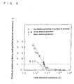
- Fig. 6 is a diagram showing the influence of the electrical resistance between one electrode and the other electrode upon the surface defects of a cold-rolled product.
- the transverse axis indicates the initial electrical resistance between one electrode and the other electrode just before the start of the casting
- the longitudinal axis indicates the ratio of the electrical resistance during the casting to the initial electrical resistance where the former resistance is calculated by the current and voltage between the one electrode and the other electrode at the last stage of the casting.
- mark ⁇ indicates a value for the products, which include a few surface defects within the above-mentioned rate of generating the defects being 0.5 %
- mark ⁇ indicates a value for the products, which include the surface defects within the above-mentioned rate of generating the defects being 1.0 %. It is noted that there are no serious problems in the case of the defects being included within the rate of generating the defects of 1.0 %.
- mark X indicates a value for products have the surface defects with the rate of generating the defects of more than 5 %. The drawing shows the experimental results obtained for the various initial electrical resistances by changing the implementation of the electrical insulation.
- the initial electrical resistance of not less than 500 ⁇ may suppress the generation of the surface defects of the products.
- the electrical resistance which is determined from the current and voltage between the one electrode and the other electrode in the last stage of casting is less than 1/10 of the initial electrical resistance, products having a better surface quality can be obtained.
- the lower limit for the ratio of the electrical resistance during the casting to the initial electrical resistance should be ideally zero, it tends to be 0.00001/10 in an actual apparatus for supplying the molten steel from the tundish into the mold.
- a gas purging part constituted by a porous refractory material can be disposed in one or more than one of the upper nozzle 2, the sliding gate 3 and the immersion nozzle 4.
- the gas purging part can be used as follows:
- an inert gas is purged into the immersion nozzle 4 in order to prevent the Al oxide deposition onto the inner surface thereof. Moreover, in order to avoid the trouble in the passage of the immersion nozzle resulting from the solidification of the molten steel at the start of casting operation, or in order to improve the molten steel stream in the mold, such an inert gas is also purged thereinto.
- the other electrode(s) 6 can be disposed in one or two of the upper nozzle 2, the sliding gate 3 and the immersion nozzle 4, or more preferably in the immersion nozzle 4, and the gas purging part(s) can be disposed in one or two of the elements in which the other electrode(s) 6 is/are not disposed.
- both the other electrode 6 and the gas purging part are not disposed in one element, thereby making it possible to prevent a reduction in the mechanical strength of the refractory materials.
- the one electrode 5 is disposed in such a manner that an end thereof passes through the sidewall of the tundish 1 and reaches the inner space of the tundish 1.
- the one electrode 5 can be disposed in such a manner that the end thereof does not pass through the sidewall of the tundish 1, but reaches the inner space of the tundish 1 from the above part thereof.
- a part of the sidewall of the tundish 1 is formed by a refractory material having a good electrical conductivity, and this part can be used as the one electrode 5.
- the upper nozzle 2 or the sliding gate 3 is constituted by a refractory material having a good electrical conductivity
- the one electrode 5 can be disposed in the upper nozzle 2 or the sliding gate 3.
- one or both of the sliding gate 3 and the immersion nozzle 4 are constituted by a refractory material having a good electrical conductivity
- the other electrode 6 is disposed in one or both of these elements.
- one electrode 5 is disposed in the sliding gate 3
- one or both of the upper nozzle 2 and the immersion nozzle 4 are constituted by a refractory material having a good electrical conductivity, and the other electrode 6 is disposed in one or both of these elements.
- an insulating element is interposed between the element including the one electrode 5 and the element including the other electrode 6.
- an insulating element can be interposed between the upper nozzle 2 and the tundish 1 in order to prevent the electrical current from flowing into the tundish 1.
- the apparatus for supplying molten steel is disposed above the mold 9, and the molten steel 8 in the tundish 1 is supplied into the mold 9 via the upper nozzle 2, the sliding gate 3 and the immersion nozzle 4.
- the power supply 7 is turned on.
- the one electrode 5 and the other electrode 6 are connected to the power supply 7 via lead wires 7a.
- the one electrode 5 is immersed in the molten steel stored in the tundish 1 and the other electrode 6 is disposed in the immersion nozzle 4 constituted by the refractory material having a good electrical conductivity, thereby enabling the electrical current to be supplied between the inner surface of the immersion nozzle 4 and the molten steel passing through the inside of the immersion nozzle 4.
- Either an AC or DC current can be employed for the current supply.
- the DC current either positive or negative potential can be applied to the immersion nozzle, and either a pulse-like or rectangular waveform is allowed to apply the current.
- the current can be supplied either continuously or intermittently.
- the current density on the surface of the conductive part made of the refractory material having a good electrical conductivity can be maintained to be 0.001 to 0.3 amperes/cm 2 (A/cm 2 ).
- A/cm 2 amperes/cm 2
- the apparatus such as the power supply 7, the lead wires and etc. becomes on a large scale, and therefore it is necessary to supply a greater amount of electrical power.
- the effect of preventing the deposition cannot be obtained at a current density of less than 0.001 A/cm 2 , and a more preferable condition of operation can be obtained at a current density of 0.01 to 0.1 A/cm 2 .
- the voltage applied between the other electrode 6 and the one electrode 5 can be determined in accordance with the above-mentioned current density, the electrical resistance of the refractory material and the electrical resistance of the material deposited on the inner surface of the refractory material, and it can be set preferably at 0.5 to 100 volts (V).
- V volts
- the effective current cannot flow due to the resistance in the current channel, thereby making it difficult to detect the applied current and voltage.
- the upper limit of the applied voltage i.e., 100 V
- a required current may be obtained if the resistance for the current channel can properly be preset.
- an applied voltage of more than 100 V a danger of receiving an electric shock takes place and the degree of danger abruptly increases with the increase of the applied voltage. From these facts, it follows that the more preferable voltage to be applied ranges from 1 to 60 V.
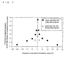
- Fig. 7 is a diagram showing the relationship between the thickness of the deposited material, such as Al oxide or the like on the inner surface of the immersion nozzle 4, and the voltage applied between the one electrode 5 and the other electrode 6, in which case the immersion nozzle 4 was constituted by a refractory material having a good electrical conductivity and the other electrode 6 was embedded in the immersion nozzle 4, and then the continuous casting was carried out under the same conditions as those in the example 1 which will be later described.
- the same structural arrangement is used regarding both the channel of supplying the current and the contact area of the refractory material with the molten steel, and the current and the current density increase with the voltage.
- the thickness of the deposited material is 13 mm or so at a potential of 0 (zero), and it decreases to be 8 mm or so, when the potential is set to be +1 V or -1 V. Moreover, when the potential is set to be +5 V or -5 V, the thickness of the deposited material further decreases to be about 4 mm. The thickness of the deposited material is smaller by 5 mm than those obtained at a potential of 0 in the case of flowing argon at a flow rate of 20 liters (Nl)/min (mark ⁇ ).
- the thickness of the deposited material When the potential is set to be +20 V or -20 V, the thickness of the deposited material further decreases to be 1 mm or so. Although no clear difference can be found in the diagram, it can be discerned that the thickness of the material deposited on the inner surface of the immersion nozzle 4 tends to be smaller at a negative (-) potential applied to the immersion nozzle 4, compared with that at a positive (+) potential.
- the electrical current is supplied between the inner surface of the immersion nozzle 2 and the molten steel 8 passing through the inside thereof, and under this condition, the molten steel 8 in the tundish 1 is supplied into the mold 9.
- mold powder 11 is poured on the meniscus of the molten steel in the mold 9.
- the molten steel 8 supplied into the mold 9 solidified as shell 10 on the surface of the mold 9, and then withdrawn by means of a withdrawing apparatus (not shown) to form the slab.
- the molten steel-supplying member having the gas purging part in the upper nozzle 2 is used, and an inert gas is purged into the molten steel passing through the upper nozzle 2 in such a manner that no surface defects due to the gas bubbles entering from the upper nozzle generate on the slab surface.
- the oxide particles in the molten steel rise together with the gas bubbles to the surface of the molten steel, and are captured by the molten mold flux on the meniscus of the molten steel, thereby enabling the particles to be removed from the molten steel.
- the flow rate of the inert gas to be purged should be set to be 2 to 10 liters (Nl)/min in accordance with the size of the slab.
- the apparatus for supplying molten steel according to the present invention is most suitable for using in the method for continuously casting of Al killed steel.
- the apparatus for supplying molten steel according to the present invention is not restricted to the above, and it can also be applied to the continuous casting of a metal including, for instance, zirconium, calcium, rare-earth metal or the like, which induces immersion nozzle clogging or the like, since the deposition of the oxide of these metals on the inner surface of the immersion nozzle can be prevented.
- a continuous casting machine of vertical bending type equipped with an apparatus for supplying molten steel was used wherein said apparatus comprising an upper nozzle, a sliding gate and an immersion nozzle, more than one thereof being constituted by a refractory material having a good electrical conductivity, and the other electrode was embedded in the above element constituted by the refractory material having a good electrical conductivity.
- a gas purging part was disposed in the upper nozzle or the upper plate in the sliding gate, and a gas was purged at a small flow rate of 3 to 5 Nl/min to open the sliding gate in the initial stage of casting.
- the immersion nozzle having a 90 mm inside diameter and two exit ports directed downward at an inclination angle of 35° was used.
- the element, in which the other electrode was embedded, was formed by a refractory material having a good electrical conductivity, said material comprising an alumina graphite composed of 22 wt % graphite, 12 wt % SiO 2 , and the residual being alumina and impurities.
- Either a sheet comprising fibers of alumina and silica or a refractory material made of alumina was interposed between an element in which the other electrode was embedded and an element adjacent thereto, and thus these elements are insulated from each other.
- the one electrode formed by alumina graphite was immersed into the molten steel in the tundish from the upper surface thereof.
- the other electrode made of graphite or steel was positioned in varied locations.
- the upper nozzle, the sliding gate and the immersion nozzle were individually collected, and then cut in the longitudinal direction in order to determine the thickness of the material deposited on the inner surface thereof.
- the thickness of the material deposited on the inner surface of those of the upper nozzle, the sliding gate and the immersion nozzle, in that the other electrode(s) was(were) disposed was determined by the following procedures: The inside diameters of the above-mentioned element at three different longitudinal positions and at two different surrounding positions were measured, and an averaged value of the inside diameters thus measured was determined. The thickness was determined by 1/2 of the difference between the average value and the initial inside diameter before the casting.
- the slab produced was hot-rolled to form a steel strip having a thickness of 4 to 6 mm.
- the steel strip thus formed was pickled and then further cold-rolled to form a steel strip having a thickness of 0.8 to 1.2 mm.
- the surface defects were inspected with the naked eye.
- the parts in which the surface defects were included were cut and the total accumulated length of the cut pieces was determined.
- the rate of surface defects was determined by dividing the total length by the initial length of the steel strip.
- the results are also listed in the table 2. From the results in the table 2, the following can be recognized:
- Test No. 1 no potential is applied and an Ar gas was purged at a very small flow rate of 5 Nl/min for opening the sliding gate in the initial stage of casting, so that the thickness of the material deposited on the inner surface of the immersion nozzle was relatively thick, i.e., 31.4 mm and the rate of surface defects was relatively high, i.e., 9.6 %.
- Test No. 2 no potential was applied and the Ar gas was purged at a relatively large rate of 20 Nl/min, so that the thickness of the material deposited on the inner surface of the immersion nozzle was 5.4 mm, thinner than that in the case of the Test No. 1, and the rate of surface defects was 3.8 % and thus relatively low.
- Test No. 11 a potential of 5 V was applied to the immersion nozzle in which the other electrode was disposed, and an AC current was supplied thereto.
- the thickness of the material deposited on the inner surface of the refractory material (immersion nozzle) and the rate of surface defects were the same as those in Tests No. 4 and No. 7 in which the same potential was applied and the DC was supplied.
- Test No Type of steel Embedded position of the other electrode (*1) Applied voltage (V) Supplied current (A/cm 2 )
- Test No. 12 a potential of +2 V was applied to the sliding gate as an Ar gas purging part in which the other electrode was embedded, and a DC current was supplied thereto. In this case, the casting could not be carried out because the sliding gate was consumed due to an erosion. Although, in the case of the Tests No. 9 and No. 10, there were no problems even when the other electrode was embedded in the immersion nozzle, the erosion of the sliding gate caused the interruption of the casting operation.
- the other electrode was embedded in the sliding gate in which the Ar gas purging part was not disposed.
- An potential of +2 V or -5 V was applied to the sliding gate, and a DC current was supplied thereto.
- the thickness of the material deposited on the inner surface of the refractory material (sliding gate) was relatively thin, but the rate of surface defects was lower than that in the case of the current being supplied to the nozzle.
- an slab having a 270 mm thickness and a 1200 to 1600 mm width was cast at the casting rate of 1.4 to 1.7 m/min.
- the material of the immersion nozzle was alumina graphite which included 31 wt % graphite, 14 wt % SiO 2 and residual composed mostly of Al 2 O 3 and had a good electrical conductivity at a temperature of molten steel.
- the one electrode made of carbon steel was mounted onto the outer surrounding of the immersion nozzle and the other electrode made of alumina graphite was immersed into the molten steel from the surface thereof in the tundish.
- a sheet comprising refractory fibers having Al 2 O 3 and SiO 2 as main components and/or antioxidant including SiO 2 as a main component was interposed either between the immersion nozzle and the sliding gate being in contact therewith, or between the immersion nozzle and the holder for supporting the immersion nozzle on the sliding gate in order to insulate the two elements from each other.
- the thickness of the sheet and the antioxidant was varied.
- the tundish, the upper nozzle, the sliding gate and the immersion nozzle was preheated for about 3 hours using an usual combustion gas, and the refractory lining of the tundish was set at a surface temperature of 1,000 to 1,200 °C.
- the initial electrical resistance between the one electrode and the other electrode was measured just before the end of the preheating.
- molten steel having a weight of about 270 t per heat was six times sequentially cast. Either a constant current or a constant voltage was applied between the one electrode and the other electrode for the period from the start to the end of the casting. In this case, the applied current was 10 to 100 A and the applied voltage was 3 to 80 V. From the current and voltage, the electrical resistance between the one electrode and the other electrode during the casting was determined.
- the immersion nozzle was collected and cut in the longitudinal direction in order to inspect the existence of the material deposited on the inner surface thereof and to measure the thickness of the deposited material.
- the respective slabs obtained in the second heat and the sixth heat were hot-rolled to form a steel strip having a thickness of 4 to 6 mm and then pickled. Thereafter, the steel strip was further cold-rolled to form a steel strip having a thickness of 1.6 to 1.2 mm.
- the inspection was then carried out regarding the existence of surface defects and the state of surface defects in the products. At the same time, the rate of surface defects in the product was determined.
- the thickness of the material deposited on the immersion nozzle was 5 mm, thereby providing a good result. Furthermore, the rates of surface defects in the products, which were produced by the slabs obtained in the second and sixth heats, were 0.6 % and 0.9 %, respectively, and thereby relatively good results were obtained.
- a 4.0 mm thick sheet was inserted between the immersion nozzle and the sliding gate. Moreover, a 1.0 mm thick sheet was inserted between the immersion nozzle and the holder, and at the same time an antioxidant was inserted therebetween in a thickness of 0.5 mm.
- the initial electrical resistance between the one electrode and the other electrode just before the end of the preheating the tundish in the casting was 1,200 ⁇ . This value was within the range specified by the scope of the present invention.
- the initial electrical resistance was two times greater than that in Test No. 29. This fact may be due to that the thickness between the immersion nozzle and the sliding gate is greater than that in Test No. 29 and the additional sheet was interposed between the immersion nozzle and the holder, together with the antioxidant inserted therebetween.
- the electrical resistance during the casting just before the end of the sixth heat in the casting was 8 ⁇ , so that the resistance ratio was 0.07/10, thereby residing within the preferable range.
- the thickness of the material deposited on the immersion nozzle was 4 mm, thereby providing a good result.
- the rates of generating the defects in the products, which were produced by the slabs obtained in the second and sixth heats were 0.3 % and 0.4 %, respectively, and thereby relatively good results were obtained.
- Test No. 31 the method for implementing the insulation was the same as that in Test No. 30.
- the initial electrical resistance between the one electrode and the other electrode just before the end of the preheating the tundish in the casting was 1,050 ⁇ .
- the electrical resistance during the casting just before the end of the sixth heat in the casting was 0.5 ⁇ and the increase of the resistance during the casting was small. As a result, the resistance ratio was 0.005/10, thereby residing within the range of the preferable conditions.
- the thickness of the material deposited on the immersion nozzle after the casting was 2 mm, thereby providing a good result.
- the rates of surface defects in the products, which were produced by the slabs obtained in the second and sixth heats were 0.3 %, respectively, and thereby relatively good results were obtained.
- the thickness of the material deposited on the immersion nozzle after the casting was 1 mm, and this very small value indicates the best result. Furthermore, the rates of surface defects in the products, which were produced by the slabs obtained in the second and sixth heats, were 0.1 % and 0.2 %, respectively, and thereby good results were obtained.
- the thickness of the sheet was 2.0 mm and the thickness of the coated film was 0.6 mm.
- the initial electrical resistance between the one electrode and the other electrode just before the end of the preheating the tundish in the casting was 420 ⁇ . This value was very small and outside of the range specified by the scope of the present invention.
- the electrical resistance during the casting just before the end of the sixth heat in the casting was 64 ⁇ and therefore the resistance ratio increased to 1.5/10 and was outside of the preferable condition.
- the thickness of the material deposited on the immersion nozzle was 7 mm and relatively thick.
- the rates of surface defects in the products, which were produced by the slabs obtained in the second and sixth heats were 0.8 % and 7.9 %, respectively. In particular, unsatisfactory results were obtained for the sixth heat.
- the immersion nozzle was collected and cut in the longitudinal direction in order to inspect the material deposited on the surface in the vicinity of the exit ports regarding the existence of the deposit and the state of deposition. Furthermore, the slab thus obtained was cold-rolled to form a steel strip having a thickness of 0.8 to 1.2 mm by utilizing the same method as that in EXAMPLE 1, and then the inspection was carried out regarding the rate of surface defects, using the same method as that in EXAMPLE 1. The test conditions and the obtained results are listed in the table 4. Ar gas purging Test No.
- Type of steel Embedded position of the other electrode (*1) Applied voltage (V) Supplied current (A/cm 2 ) Type of current Current supplying part Upper nozzle (Nl/min) Thickness of material deposited on inner surface of refractory material (mm) Rate of surface defects (%) 36 A A 17 0.17 DC No 5 3.0 1.8 37 A A -17 0.17 DC No 5 1.3 0.2 38 A A 10 0.092 DC No 5 3.5 2.1 39 A A -10 0.092 DC No 5 1.8 0.3 40 A A ⁇ 17 0.17 AC No 5 3.0 1.8 41 A - - - - Without Nozzle 20 5.0 2.3 42 A - - - - Without Nozzle 5 13 5.1 (*1) The position A at which the other electrode is embedded indicates the immersion nozzle.
- Test No. 36 a positive potential was applied to the immersion nozzle and a DC current was supplied thereto at a current density of 0.17 A/cm 2 .
- the thickness of the material deposited on the inner surface of the immersion nozzle was 3.0 mm and the rate of surface defects was 1.8 %.
- Test No. 37 a negative potential was applied to the immersion nozzle and the other conditions were the same as those in Test No. 36.
- the thickness of the material deposited on the inner surface of the immersion nozzle was 1.3 mm and the rate of surface defects was 0.2 %, so that the thickness of the deposited material and the rate of surface defects were better than those in Test No. 36.
- Test No. 38 a positive potential was applied to the immersion nozzle and a DC current was supplied thereto at a current density of 0.092 A/cm 2 .
- the thickness of the material deposited on the inner surface of the immersion nozzle was 3.5 mm and the rate of surface defects was 2.1 %.
- Test No. 39 a negative potential was applied to the immersion nozzle and the other conditions were the same as those in Test No. 38.
- the thickness of the material deposited on the inner surface of the immersion nozzle was 1.8 mm and the rate of surface defects was 0.3 %, so that the thickness of the deposited material and the rate of surface defects were better than those in Test No. 38.
- Test No. 40 an AC current was supplied at a current density of 0.17 A/cm 2 and the other conditions were the same as those in Test No. 36.
- the thickness of the material deposited on the inner surface of the immersion nozzle in the vicinity of the discharge holes was 3.0 mm and the rate of surface defects was 1.8 %, so that the thickness of the deposited material and the rate of surface defects were similar to those in Test No. 36.
- Test No. 41 no current was supplied and an Ar gas was purged from the sliding gate into the molten steel at a flow rate of 20 liters (Nl)/min.
- the thickness of the material deposited on the inner surface of the immersion nozzle in the vicinity of the discharge holes was 5.0 mm and the rate of surface defects was 2.3 %, so that the thickness of the deposited material and the rate of surface defeccts were relatively unsatisfactory.
- the deposition of Al oxide or the like in the molten steel on the inner surface of the upper nozzle, the flow control mechanism and the immersion nozzle can securely be prevented.
- the application of the continuous casting method with the apparatus for supplying molten steel makes it possible to prevent the products manufactured by the obtained slab from generating the surface defects caused by defects such as mold flux, Al oxide, gas bubbles in the slab.
- the continuous casting method effectively prevents the immersion nozzle clogging during the casting, thereby enabling the applicability to be provided over a wide area of the continuous casting.
Landscapes
- Engineering & Computer Science (AREA)
- Mechanical Engineering (AREA)
- Casting Support Devices, Ladles, And Melt Control Thereby (AREA)
- Continuous Casting (AREA)
Abstract
Description
| Type of steel | Chemical composition of molten steel, residual being Fe and impurities (unit: weight %) | ||||||
| C | Si | Mn | P | S | Al | Ti | |
| A | 0.04-0.06 | 0.03-0.04 | 0.16-0.23 | 0.010-0.025 | 0.008-0.012 | 0.03-0.05 | - |
| B | 0.001-0.003 | 0.02-0.04 | 0.09-0.18 | 0.008-0.035 | 0.008-0.013 | 0.03-0.05 | 0.01-0.04 |
b: the surface area of the conductive part on the inner surface of the refractory material, facing the molten steel, being coupled to the other electrode and (cm2)
| Test No | Type of steel | Embedded position of the other electrode (*1) | Applied voltage (V) | Supplied current (A/cm2) | Type of current | Ar gas purging | Thickness of material deposited on inner surface of refractory material (mm) | Surface defect generating rate (%) | |||
| . | Current supplying part | Upper nozzle (Nl/min) | |||||||||
| 1 | A | - | - | - | - | Without | 5 5 | 13,4 (nozzle) | 9.6 | ||
| 2 | A | - | - | - | - | Without | 20 | 5.4 (nozzle) | 3.8 | ||
| 3 | | A | 2 | 0.017 | | No | 5 | 6.2 | 2.3 | ||
| 4 | | A | 5 | 0.034 | | No | 5 | 4.3 | 1.4 | ||
| 5 | | A | 20 | 0.066 | | No | 5 | 1.2 | 0.4 | ||
| 6 | A | A | ·2 | 0.017 | DC | No | 5 | 5.7 | 1.6 | ||
| 7 | A | A | -5 | 0.034 | DC | No | 5 | 3.6 | 0.7 | ||
| 8 | A | A | -20 | 0.066 | DC | No | 5 | 0.9 | 0.2 | ||
| 9 | A | A | 2 | 0.017 | DC | Yes | 5 | 5.7 | 1.6 | ||
| 10 | A | A | -2 | 0.017 | DC | Yes | 5 | 5.7 | 1.6 | ||
| 11 | A | A | ±5 | 0.034 | AC | No | 5 | 4.1 | 1.1 | ||
| 12 | A | B | 2 | 0.049 | DC | Yes | 5 | (*2)- | (*2)- | ||
| 13 | A | B | 2 | 0.049 | DC | No | 5 | 6.2 | 2.2 | ||
| 14 | A | B | -5 | 0.122 | DC | No | 5 | 5.6 | 1.4 | ||
| 15 | A | C | -5 | 0.095 | DC | No | 5 | 4.5 | 1.4 | ||
| 16 | A | A+C | 2 | 0.011 | DC | No | 5 | 5.6 | 2.1 | ||
| 17 | A | A+C | -5 | 0.027 | DC | No | 5 | 3.8 | 0.6 | ||
| 18 | B | - | - | - | - | No | 7 | 12.5 | 7.6 | ||
| 19 | B | A | 12 | 0.055 | DC | No | 7 | 3.2 | 1.9 | ||
| 20 | B | A | 5 | 0.034 | DC | No | 7 | 2.3 | 1.6 | ||
| 21 | B | A | 1.2 | 0.006 | DC | No | 7 | 4.8 | 2.8 | ||
| 22 | B | A | 0.6 | 0.0009 | DC | No | 7 | 10.3 | 7.1 | ||
| 23 | B | A | -12 | 0.055 | DC | No | 7 | 1.6 | 1.2 | ||
| 24 | B | A | -5 | 0.034 | DC | No | 7 | 0.4 | 0.7 | ||
| 25 | B | A | -1.2 | 0.006 | DC | No | 7 | 4.2 | 2.5 | ||
| 26 | B | A | -0.6 | 0.0009 | DC | No | 7 | 9.8 | 6.4 | ||
| 27 | B | A | ±5 | ±10.034 | AC | No | 7 | 2 | 1.4 | ||
| (*1) the positions A, B and C at which the other electrode is embedded are as follows: A: immersion nozzle, B: sliding gate, C: upper nozzle | |||||||||||
| (*2) No data obtained due to the fracture of the sliding gate |
| Test conditions | Test results | |||||||
| Test No. | Method for implementing insulation (*1) | Electrical resistance and the electrical resistance ratio | Thickness material deposited on the inner surface of immersion nozzle (mm) | Rate of surface defects (%) | ||||
| Between immersion nozzle and gate | Between immersion nozzle and holder | After preheating tundish (X) | Before the end of 6th heat of casting (Y) | Value (Y)/(X) | Slab in 2nd heat used as material | Slab in 6th heat used as material | ||
| 28 | A 2.5 | B 0.2 | 600 | 72 | 1.2/10 | 5 | 0.6 | 0.9 |
| 29 | A 2.5 | B 0.4 | 600 | 58 | 0.97/10 | 4 | 0.3 | 0.5 |
| 30 | A 4.0 | A+B 1.5 | 1,200 | 8 | 0.07/10 | 2 | 0.3 | 0.4 |
| 31 | A 4.0 | A+B 1.5 | 1,050 | 0.5 | 0.005/10 | 1 | 0.3 | 0.3 |
| 32 | A(*2) 5 | A+B 2.5 | 380 x 103 | 13 | 0.0003/10 | 1 | 0.1 | 0.2 |
| 33 | A 2.0 | B 0.6 | 420 * | 64 | 1.5/10 | 7 | 0.8 | 7.9 |
| 34 | B 0.7 | B 0.5 | 30 * | 32 | 10.6/10 | 11 | 8.4 | 12.3 |
| 35 | No implemen tation | No implemen tation | No measure ment | No measure ment | - | 13 | 9.8 | 11.8 |
| (*1): A; sheet of refractory fiber material, B; coating of antioxidant of SiO2 system, numerical values; thickness of single element or whole element (mm) | ||||||||
| (*2): A 3 mm thick alumina plate interposed only for Test No. 32 | ||||||||
| * indicating the deviation from the conditions specified by the scope of the present invention |
| Ar gas purging | |||||||||||
| Test No. | Type of steel | Embedded position of the other electrode (*1) | Applied voltage (V) | Supplied current (A/cm2) | Type of current | Current supplying part | Upper nozzle (Nl/min) | Thickness of material deposited on inner surface of refractory material (mm) | Rate of surface defects (%) | ||
| 36 | A | A | 17 | 0.17 | | No | 5 | 3.0 | 1.8 | ||
| 37 | A | A | -17 | 0.17 | | No | 5 | 1.3 | 0.2 | ||
| 38 | | A | 10 | 0.092 | | No | 5 | 3.5 | 2.1 | ||
| 39 | A | A | -10 | 0.092 | | No | 5 | 1.8 | 0.3 | ||
| 40 | A | A | ±17 | 0.17 | | No | 5 | 3.0 | 1.8 | ||
| 41 | A | - | - | - | - | Without | 20 | 5.0 | 2.3 | ||
| 42 | A | - | - | - | - | Without | 5 | 13 | 5.1 | ||
| (*1) The position A at which the other electrode is embedded indicates the immersion nozzle. |
Claims (11)
- An apparatus for supplying molten steel used for the continuous casting, comprising a tundish for storing the molten steel, an upper nozzle disposed in the bottom of the tundish, a flow control mechanism for controlling the flow rate of the molten steel from the tundish into a mold and an immersion nozzle for supplying the molten steel into the mold, wherein providing a pair of electrodes and a power supply connected thereto, and forming the inner surface, being in contact with the molten steel, of one of the upper nozzle, the flow control mechanism and the immersion nozzle by a refractory material having a good electrical conductivity at a temperature not less than the melting point of steel, wherein disposing the one electrode of the paired electrodes in one of the upper nozzle, the flow control mechanism and the immersion nozzle in such a way that the one electrode reaches the inner space of thereof and is in contact with the molten steel, wherein disposing the other electrode in a part formed by the refractory material having a good electrical conductivity.
- An apparatus for supplying molten steel used for the continuous casting according to Claim 1, wherein the electrical conductivity of the refractory material having a good electrical conductivity at a temperature not less than the melting point of steel is not less than 1 x 10³ S/m.
- An apparatus for supplying molten steel used for the continuous casting according to Claim 1 or 2, wherein the refractory material having a good electrical conductivity at a temperature not less than the melting point of steel comprises an alumina graphite.
- An apparatus for supplying molten steel used for the continuous casting according to one of Claims 1 to 3, wherein an insulating element is interposed between the one electrode and the other electrode.
- An apparatus for supplying molten steel used for the continuous casting according to one of Claims 1 to 4, wherein a gas purging part is disposed in one or more than two of the upper nozzle, the flow control mechanism and the immersion nozzle which have no electrode.
- A continuous casting method, wherein supplying a molten steel stored in a tundish into a mold using an apparatus for supplying molten steel according to one of Claims 1 to 5, and supplying an electric current between the inner surface of the upper nozzle, the flow control mechanism and the immersion nozzle in which the other electrode of the paired electrodes is disposed and the molten steel passing through the inside thereof.
- A continuous casting method, wherein, in the case of supplying a molten steel stored in a tundish into a mold using an apparatus for supplying molten steel according to one of Claims 1 to 5, setting the electrical resistance between the one electrode and the other electrode to be not less than 500 Ω, either at the end of preheating the tundish before the molten steel is supplied to the tundish, or before the molten steel is supplied to the tundish if the tundish which is once used for casting is recycled for casting without preheating.
- A continuous casting method according to Claim 7, wherein controlling the electrical resistance determined from the current and voltage applied between the one electrode and the other electrode during a period from the start and to the end of casting to be less than 1/10 of the electrical resistance between the one electrode and the other electrode, either at the end of preheating the tundish before the molten steel is supplied to the tundish, or before the molten steel is supplied to the tundish if the tundish which is once used for casting is recycled for casting without preheating.
- A continuous casting method according to one of Claims 6 to 8, wherein a current is supplied at a current density of not less than 0.001 A/cm2 and less than 0.3 A/cm2.
- A continuous casting method according to one of Claims 6 to 9, wherein the applied voltage is not less than 0.5 V and not more than 100 V.
- A continuous casting method, wherein, in the case of supplying a molten steel stored in a tundish into an apparatus for supplying molten steel according to one of Claims 1 to 5, forming at least the immersion nozzle by a refractory material having a good electrical conductivity at a temperature not less than the melting point of steel, and disposing the other electrode therein, applying a negative potential to the immersion nozzle and supplying a DC current between the immersion nozzle and the molten steel passing through the inside of the immersion nozzle to prevent the immersion nozzle clogging.
Applications Claiming Priority (7)
| Application Number | Priority Date | Filing Date | Title |
|---|---|---|---|
| JP2000392252 | 2000-12-25 | ||
| JP2000392252 | 2000-12-25 | ||
| JP2001175722 | 2001-06-11 | ||
| JP2001175722 | 2001-06-11 | ||
| JP2001246524 | 2001-08-15 | ||
| JP2001246524 | 2001-08-15 | ||
| PCT/JP2001/011409 WO2002051570A1 (en) | 2000-12-25 | 2001-12-25 | Molten steel feeder for continuous casting, and method for continuous casting using the molten steel feeder |
Publications (3)
| Publication Number | Publication Date |
|---|---|
| EP1348503A1 true EP1348503A1 (en) | 2003-10-01 |
| EP1348503A4 EP1348503A4 (en) | 2005-03-23 |
| EP1348503B1 EP1348503B1 (en) | 2008-06-25 |
Family
ID=27345528
Family Applications (1)
| Application Number | Title | Priority Date | Filing Date |
|---|---|---|---|
| EP01272322A Expired - Lifetime EP1348503B1 (en) | 2000-12-25 | 2001-12-25 | Continuous casting method using a molten steel feeder |
Country Status (9)
| Country | Link |
|---|---|
| US (1) | US6598662B2 (en) |
| EP (1) | EP1348503B1 (en) |
| KR (1) | KR20020086900A (en) |
| CN (1) | CN1400929A (en) |
| BR (1) | BR0108635A (en) |
| CA (1) | CA2399957A1 (en) |
| DE (1) | DE60134573D1 (en) |
| ES (1) | ES2305030T3 (en) |
| WO (1) | WO2002051570A1 (en) |
Cited By (1)
| Publication number | Priority date | Publication date | Assignee | Title |
|---|---|---|---|---|
| WO2004099694A3 (en) * | 2003-05-08 | 2005-02-24 | Saveway Gmbh & Co Kg | Refractory component consisting of a ceramic material |
Families Citing this family (13)
| Publication number | Priority date | Publication date | Assignee | Title |
|---|---|---|---|---|
| CN101583447B (en) * | 2007-01-25 | 2011-12-28 | 住友金属工业株式会社 | Continuous casting method of steel |
| CN101850406B (en) * | 2010-06-30 | 2012-02-08 | 西安建筑科技大学 | A graphite electrode for applying pulse current to continuous casting tundish |
| DE102011050149A1 (en) * | 2010-11-17 | 2012-05-24 | Ferrofacta Gmbh | Die casting nozzle and die casting process |
| KR20170005469A (en) | 2014-05-21 | 2017-01-13 | 노벨리스 인크. | Non-contacting molten metal flow control |
| CN104511586B (en) * | 2014-12-05 | 2017-09-29 | 澳洲澳秀科技有限公司 | Spray nozzle device for conticaster and the continuous casting tundish including the device |
| SK892016A3 (en) | 2016-10-10 | 2018-07-02 | I.P.C. Refractories, Spol. S R.O. | A method of casting molten metal using an impact plate in a tundish |
| CN109759573A (en) * | 2019-03-19 | 2019-05-17 | 东北大学 | A method of using pulse current to inhibit submersed nozzle inner wall dross |
| CN109732072B (en) * | 2019-03-19 | 2021-05-25 | 东北大学 | Method for applying same-polarity charges to inhibit inner wall accretion of submerged nozzle |
| CN113102744A (en) * | 2021-04-19 | 2021-07-13 | 辽宁科技大学 | A kind of method and operation steps of inhibiting continuous casting nozzle erosion |
| CN114309571A (en) * | 2021-12-01 | 2022-04-12 | 上海大学 | Method and device for inhibiting water gap blockage in rare earth steel continuous casting process |
| CN114769574B (en) * | 2022-06-09 | 2024-04-30 | 中钢集团洛阳耐火材料研究院有限公司 | Method for prolonging service life of integral stopper rod for continuous casting |
| KR102664187B1 (en) | 2022-10-28 | 2024-05-09 | 현대제철 주식회사 | Beam Blank and Continuous Casting Method of Beam Blank |
| CN117226084B (en) * | 2023-09-12 | 2024-05-07 | 中钢集团洛阳耐火材料研究院有限公司 | A method for reducing alumina inclusions in tundish molten steel |
Family Cites Families (9)
| Publication number | Priority date | Publication date | Assignee | Title |
|---|---|---|---|---|
| JPS5729433B2 (en) | 1974-10-30 | 1982-06-22 | ||
| JPS5159022A (en) * | 1974-11-20 | 1976-05-22 | Sumitomo Metal Ind | Renzokuchuzo niokeru tandeitsushunozurutsumariboshiho |
| JPS5839022B2 (en) * | 1979-03-31 | 1983-08-26 | 住友金属工業株式会社 | Method for preventing molten steel injection nozzle blockage |
| JPS5618168U (en) * | 1979-05-29 | 1981-02-17 | ||
| JPS5618168A (en) | 1979-07-19 | 1981-02-20 | Kubota Ltd | Flow control valve |
| LU85858A1 (en) * | 1985-04-19 | 1986-11-05 | Electro Nite | PROCESS FOR PREVENTING DEPOSITS ON THE WALLS OF METALLURGICAL CONTAINERS AND METALLURGICAL CONTAINER SUITABLE FOR IMPLEMENTING THIS PROCESS |
| JP2891307B2 (en) * | 1991-04-16 | 1999-05-17 | 新日本製鐵株式会社 | Steel continuous casting method |
| JPH04322870A (en) * | 1991-04-23 | 1992-11-12 | Fuji Electric Co Ltd | Pouring nozzle for discharging molten metal |
| JPH06182513A (en) * | 1992-12-21 | 1994-07-05 | Nippon Steel Corp | Method for blowing gas from immersion nozzle for continuous casting |
-
2001
- 2001-12-25 BR BR0108635-9A patent/BR0108635A/en not_active Application Discontinuation
- 2001-12-25 DE DE60134573T patent/DE60134573D1/en not_active Expired - Lifetime
- 2001-12-25 CN CN01805117A patent/CN1400929A/en active Pending
- 2001-12-25 WO PCT/JP2001/011409 patent/WO2002051570A1/en not_active Ceased
- 2001-12-25 CA CA002399957A patent/CA2399957A1/en not_active Abandoned
- 2001-12-25 EP EP01272322A patent/EP1348503B1/en not_active Expired - Lifetime
- 2001-12-25 ES ES01272322T patent/ES2305030T3/en not_active Expired - Lifetime
- 2001-12-25 KR KR1020027010236A patent/KR20020086900A/en not_active Ceased
-
2002
- 2002-08-13 US US10/216,772 patent/US6598662B2/en not_active Expired - Lifetime
Cited By (1)
| Publication number | Priority date | Publication date | Assignee | Title |
|---|---|---|---|---|
| WO2004099694A3 (en) * | 2003-05-08 | 2005-02-24 | Saveway Gmbh & Co Kg | Refractory component consisting of a ceramic material |
Also Published As
| Publication number | Publication date |
|---|---|
| ES2305030T3 (en) | 2008-11-01 |
| US6598662B2 (en) | 2003-07-29 |
| EP1348503B1 (en) | 2008-06-25 |
| CN1400929A (en) | 2003-03-05 |
| WO2002051570A1 (en) | 2002-07-04 |
| DE60134573D1 (en) | 2008-08-07 |
| US20030006022A1 (en) | 2003-01-09 |
| EP1348503A4 (en) | 2005-03-23 |
| BR0108635A (en) | 2002-12-10 |
| KR20020086900A (en) | 2002-11-20 |
| CA2399957A1 (en) | 2002-07-04 |
Similar Documents
| Publication | Publication Date | Title |
|---|---|---|
| US6598662B2 (en) | Molten steel supplying apparatus for continuous casting and continuous casting method therewith | |
| JP5316327B2 (en) | Steel continuous casting method | |
| JP3747848B2 (en) | Continuous casting method | |
| US5799720A (en) | Nozzle assembly for continuous caster | |
| US7575135B2 (en) | Immersion nozzle for continuous casting of steel and method of continuous casting method of steel | |
| JP5869748B2 (en) | Continuous casting method of Al killed steel | |
| JP4296787B2 (en) | Immersion nozzle for continuous casting of steel and method for continuous casting of steel | |
| JP5316328B2 (en) | Steel continuous casting method | |
| JP4231176B2 (en) | Stopper for metallurgy container and / or upper nozzle | |
| JP2002336942A (en) | Immersion nozzle for continuous casting and continuous casting method | |
| JP5370171B2 (en) | Steel continuous casting method | |
| JP2001170742A (en) | Sliding nozzle of metallurgical vessel | |
| KR20170062204A (en) | Casting apparatus and casting method using the same | |
| JP3633514B2 (en) | Immersion nozzle for continuous casting and method for continuous casting of metal | |
| KR20110064040A (en) | Insert nozzle for insertion and guidance of core material, composite wire manufacturing device and manufacturing method using the same | |
| JP2006231397A (en) | Continuous casting method of aluminum killed steel | |
| JP2004330256A (en) | Steel continuous casting method | |
| JP6167778B2 (en) | Steel continuous casting method | |
| JP3114004B2 (en) | Nozzle and continuous casting method | |
| JP2002210546A (en) | Method for producing continuously cast product | |
| JP4218515B2 (en) | Steel continuous casting method | |
| EP0218704B1 (en) | Process intended to prevent deposition on the walls of metallurgical containers and metallurgical container suitable for carrying out this process | |
| JP4218391B2 (en) | Continuous casting method for molten steel | |
| JPH06182513A (en) | Method for blowing gas from immersion nozzle for continuous casting | |
| JP2002205152A (en) | Method for producing continuously cast product |
Legal Events
| Date | Code | Title | Description |
|---|---|---|---|
| PUAI | Public reference made under article 153(3) epc to a published international application that has entered the european phase |
Free format text: ORIGINAL CODE: 0009012 |
|
| 17P | Request for examination filed |
Effective date: 20020816 |
|
| AK | Designated contracting states |
Kind code of ref document: A1 Designated state(s): AT BE CH CY DE DK ES FI FR GB GR IE IT LI LU MC NL PT SE TR |
|
| RBV | Designated contracting states (corrected) |
Designated state(s): AT BE CH CY DE ES FR GB IT LI |
|
| A4 | Supplementary search report drawn up and despatched |
Effective date: 20050208 |
|
| RIC1 | Information provided on ipc code assigned before grant |
Ipc: 7B 22D 11/10 A Ipc: 7B 22D 41/50 B Ipc: 7B 22D 41/60 B |
|
| GRAP | Despatch of communication of intention to grant a patent |
Free format text: ORIGINAL CODE: EPIDOSNIGR1 |
|
| RTI1 | Title (correction) |
Free format text: CONTINUOUS CASTING METHOD USING A MOLTEN STEEL FEEDER |
|
| RBV | Designated contracting states (corrected) |
Designated state(s): DE ES FR GB IT |
|
| GRAS | Grant fee paid |
Free format text: ORIGINAL CODE: EPIDOSNIGR3 |
|
| GRAA | (expected) grant |
Free format text: ORIGINAL CODE: 0009210 |
|
| AK | Designated contracting states |
Kind code of ref document: B1 Designated state(s): DE ES FR GB IT |
|
| REG | Reference to a national code |
Ref country code: GB Ref legal event code: FG4D |
|
| REF | Corresponds to: |
Ref document number: 60134573 Country of ref document: DE Date of ref document: 20080807 Kind code of ref document: P |
|
| REG | Reference to a national code |
Ref country code: ES Ref legal event code: FG2A Ref document number: 2305030 Country of ref document: ES Kind code of ref document: T3 |
|
| PLBE | No opposition filed within time limit |
Free format text: ORIGINAL CODE: 0009261 |
|
| STAA | Information on the status of an ep patent application or granted ep patent |
Free format text: STATUS: NO OPPOSITION FILED WITHIN TIME LIMIT |
|
| 26N | No opposition filed |
Effective date: 20090326 |
|
| REG | Reference to a national code |
Ref country code: GB Ref legal event code: 732E Free format text: REGISTERED BETWEEN 20131010 AND 20131016 |
|
| REG | Reference to a national code |
Ref country code: FR Ref legal event code: TP Owner name: NIPPON STEEL & SUMITOMO METAL CORPORATION, JP Effective date: 20131108 |
|
| REG | Reference to a national code |
Ref country code: DE Ref legal event code: R082 Ref document number: 60134573 Country of ref document: DE Representative=s name: RECHTS- UND PATENTANWAELTE LORENZ SEIDLER GOSS, DE |
|
| REG | Reference to a national code |
Ref country code: DE Ref legal event code: R081 Ref document number: 60134573 Country of ref document: DE Owner name: NIPPON STEEL & SUMITOMO METAL CORPORATION, JP Free format text: FORMER OWNER: SUMITOMO METAL INDUSTRIES, LTD., OSAKA, JP Effective date: 20140402 Ref country code: DE Ref legal event code: R082 Ref document number: 60134573 Country of ref document: DE Representative=s name: RECHTS- UND PATENTANWAELTE LORENZ SEIDLER GOSS, DE Effective date: 20140402 Ref country code: DE Ref legal event code: R082 Ref document number: 60134573 Country of ref document: DE Representative=s name: LORENZ SEIDLER GOSSEL RECHTSANWAELTE PATENTANW, DE Effective date: 20140402 |
|
| REG | Reference to a national code |
Ref country code: FR Ref legal event code: PLFP Year of fee payment: 15 |
|
| REG | Reference to a national code |
Ref country code: FR Ref legal event code: PLFP Year of fee payment: 16 |
|
| REG | Reference to a national code |
Ref country code: FR Ref legal event code: PLFP Year of fee payment: 17 |
|
| REG | Reference to a national code |
Ref country code: DE Ref legal event code: R082 Ref document number: 60134573 Country of ref document: DE Representative=s name: LORENZ SEIDLER GOSSEL RECHTSANWAELTE PATENTANW, DE Ref country code: DE Ref legal event code: R081 Ref document number: 60134573 Country of ref document: DE Owner name: NIPPON STEEL CORP., JP Free format text: FORMER OWNER: NIPPON STEEL & SUMITOMO METAL CORPORATION, TOKYO, JP |
|
| PGFP | Annual fee paid to national office [announced via postgrant information from national office to epo] |
Ref country code: FR Payment date: 20201112 Year of fee payment: 20 Ref country code: IT Payment date: 20201110 Year of fee payment: 20 Ref country code: DE Payment date: 20201216 Year of fee payment: 20 Ref country code: GB Payment date: 20201216 Year of fee payment: 20 |
|
| PGFP | Annual fee paid to national office [announced via postgrant information from national office to epo] |
Ref country code: ES Payment date: 20210119 Year of fee payment: 20 |
|
| REG | Reference to a national code |
Ref country code: DE Ref legal event code: R071 Ref document number: 60134573 Country of ref document: DE |
|
| REG | Reference to a national code |
Ref country code: GB Ref legal event code: PE20 Expiry date: 20211224 |
|
| PG25 | Lapsed in a contracting state [announced via postgrant information from national office to epo] |
Ref country code: GB Free format text: LAPSE BECAUSE OF EXPIRATION OF PROTECTION Effective date: 20211224 |
|
| REG | Reference to a national code |
Ref country code: ES Ref legal event code: FD2A Effective date: 20220405 |
|
| PG25 | Lapsed in a contracting state [announced via postgrant information from national office to epo] |
Ref country code: ES Free format text: LAPSE BECAUSE OF EXPIRATION OF PROTECTION Effective date: 20211226 |