EP1348484A2 - Heat Exchanger with Catalyst - Google Patents
Heat Exchanger with Catalyst Download PDFInfo
- Publication number
- EP1348484A2 EP1348484A2 EP03007048A EP03007048A EP1348484A2 EP 1348484 A2 EP1348484 A2 EP 1348484A2 EP 03007048 A EP03007048 A EP 03007048A EP 03007048 A EP03007048 A EP 03007048A EP 1348484 A2 EP1348484 A2 EP 1348484A2
- Authority
- EP
- European Patent Office
- Prior art keywords
- portions
- air
- cavities
- catalyst
- heat exchanger
- Prior art date
- Legal status (The legal status is an assumption and is not a legal conclusion. Google has not performed a legal analysis and makes no representation as to the accuracy of the status listed.)
- Withdrawn
Links
Images


Classifications
-
- F—MECHANICAL ENGINEERING; LIGHTING; HEATING; WEAPONS; BLASTING
- F28—HEAT EXCHANGE IN GENERAL
- F28D—HEAT-EXCHANGE APPARATUS, NOT PROVIDED FOR IN ANOTHER SUBCLASS, IN WHICH THE HEAT-EXCHANGE MEDIA DO NOT COME INTO DIRECT CONTACT
- F28D9/00—Heat-exchange apparatus having stationary plate-like or laminated conduit assemblies for both heat-exchange media, the media being in contact with different sides of a conduit wall
- F28D9/0031—Heat-exchange apparatus having stationary plate-like or laminated conduit assemblies for both heat-exchange media, the media being in contact with different sides of a conduit wall the conduits for one heat-exchange medium being formed by paired plates touching each other
- F28D9/0043—Heat-exchange apparatus having stationary plate-like or laminated conduit assemblies for both heat-exchange media, the media being in contact with different sides of a conduit wall the conduits for one heat-exchange medium being formed by paired plates touching each other the plates having openings therein for circulation of at least one heat-exchange medium from one conduit to another
-
- B—PERFORMING OPERATIONS; TRANSPORTING
- B01—PHYSICAL OR CHEMICAL PROCESSES OR APPARATUS IN GENERAL
- B01J—CHEMICAL OR PHYSICAL PROCESSES, e.g. CATALYSIS OR COLLOID CHEMISTRY; THEIR RELEVANT APPARATUS
- B01J19/00—Chemical, physical or physico-chemical processes in general; Their relevant apparatus
- B01J19/24—Stationary reactors without moving elements inside
- B01J19/2475—Membrane reactors
-
- B—PERFORMING OPERATIONS; TRANSPORTING
- B01—PHYSICAL OR CHEMICAL PROCESSES OR APPARATUS IN GENERAL
- B01J—CHEMICAL OR PHYSICAL PROCESSES, e.g. CATALYSIS OR COLLOID CHEMISTRY; THEIR RELEVANT APPARATUS
- B01J19/00—Chemical, physical or physico-chemical processes in general; Their relevant apparatus
- B01J19/24—Stationary reactors without moving elements inside
- B01J19/248—Reactors comprising multiple separated flow channels
- B01J19/249—Plate-type reactors
-
- C—CHEMISTRY; METALLURGY
- C01—INORGANIC CHEMISTRY
- C01B—NON-METALLIC ELEMENTS; COMPOUNDS THEREOF; METALLOIDS OR COMPOUNDS THEREOF NOT COVERED BY SUBCLASS C01C
- C01B3/00—Hydrogen; Gaseous mixtures containing hydrogen; Separation of hydrogen from mixtures containing it; Purification of hydrogen; Reversible storage of hydrogen
- C01B3/02—Production of hydrogen; Production of gaseous mixtures containing hydrogen
- C01B3/32—Production of hydrogen; Production of gaseous mixtures containing hydrogen by reaction of gaseous or liquid organic compounds with gasifying agents, e.g. water, carbon dioxide or air
- C01B3/323—Catalytic reaction of gaseous or liquid organic compounds other than hydrocarbons with gasifying agents
-
- C—CHEMISTRY; METALLURGY
- C01—INORGANIC CHEMISTRY
- C01B—NON-METALLIC ELEMENTS; COMPOUNDS THEREOF; METALLOIDS OR COMPOUNDS THEREOF NOT COVERED BY SUBCLASS C01C
- C01B3/00—Hydrogen; Gaseous mixtures containing hydrogen; Separation of hydrogen from mixtures containing it; Purification of hydrogen; Reversible storage of hydrogen
- C01B3/50—Separation of hydrogen or hydrogen-containing gases from gaseous mixtures, e.g. purification
- C01B3/56—Separation of hydrogen or hydrogen-containing gases from gaseous mixtures, e.g. purification by contacting with solids; Regeneration of used solids
- C01B3/58—Separation of hydrogen or hydrogen-containing gases from gaseous mixtures, e.g. purification by contacting with solids; Regeneration of used solids including a catalytic reaction
- C01B3/583—Separation of hydrogen or hydrogen-containing gases from gaseous mixtures, e.g. purification by contacting with solids; Regeneration of used solids including a catalytic reaction the reaction being the selective oxidation of carbon monoxide
-
- F—MECHANICAL ENGINEERING; LIGHTING; HEATING; WEAPONS; BLASTING
- F28—HEAT EXCHANGE IN GENERAL
- F28D—HEAT-EXCHANGE APPARATUS, NOT PROVIDED FOR IN ANOTHER SUBCLASS, IN WHICH THE HEAT-EXCHANGE MEDIA DO NOT COME INTO DIRECT CONTACT
- F28D9/00—Heat-exchange apparatus having stationary plate-like or laminated conduit assemblies for both heat-exchange media, the media being in contact with different sides of a conduit wall
- F28D9/0093—Multi-circuit heat-exchangers, e.g. integrating different heat exchange sections in the same unit or heat-exchangers for more than two fluids
-
- H—ELECTRICITY
- H01—ELECTRIC ELEMENTS
- H01M—PROCESSES OR MEANS, e.g. BATTERIES, FOR THE DIRECT CONVERSION OF CHEMICAL ENERGY INTO ELECTRICAL ENERGY
- H01M8/00—Fuel cells; Manufacture thereof
- H01M8/04—Auxiliary arrangements, e.g. for control of pressure or for circulation of fluids
- H01M8/04007—Auxiliary arrangements, e.g. for control of pressure or for circulation of fluids related to heat exchange
- H01M8/04067—Heat exchange or temperature measuring elements, thermal insulation, e.g. heat pipes, heat pumps, fins
-
- H—ELECTRICITY
- H01—ELECTRIC ELEMENTS
- H01M—PROCESSES OR MEANS, e.g. BATTERIES, FOR THE DIRECT CONVERSION OF CHEMICAL ENERGY INTO ELECTRICAL ENERGY
- H01M8/00—Fuel cells; Manufacture thereof
- H01M8/06—Combination of fuel cells with means for production of reactants or for treatment of residues
- H01M8/0662—Treatment of gaseous reactants or gaseous residues, e.g. cleaning
- H01M8/0668—Removal of carbon monoxide or carbon dioxide
-
- B—PERFORMING OPERATIONS; TRANSPORTING
- B01—PHYSICAL OR CHEMICAL PROCESSES OR APPARATUS IN GENERAL
- B01J—CHEMICAL OR PHYSICAL PROCESSES, e.g. CATALYSIS OR COLLOID CHEMISTRY; THEIR RELEVANT APPARATUS
- B01J2219/00—Chemical, physical or physico-chemical processes in general; Their relevant apparatus
- B01J2219/24—Stationary reactors without moving elements inside
- B01J2219/2401—Reactors comprising multiple separate flow channels
- B01J2219/245—Plate-type reactors
- B01J2219/2476—Construction materials
- B01J2219/2477—Construction materials of the catalysts
- B01J2219/2479—Catalysts coated on the surface of plates or inserts
-
- C—CHEMISTRY; METALLURGY
- C01—INORGANIC CHEMISTRY
- C01B—NON-METALLIC ELEMENTS; COMPOUNDS THEREOF; METALLOIDS OR COMPOUNDS THEREOF NOT COVERED BY SUBCLASS C01C
- C01B2203/00—Integrated processes for the production of hydrogen or synthesis gas
- C01B2203/02—Processes for making hydrogen or synthesis gas
- C01B2203/0205—Processes for making hydrogen or synthesis gas containing a reforming step
- C01B2203/0227—Processes for making hydrogen or synthesis gas containing a reforming step containing a catalytic reforming step
-
- C—CHEMISTRY; METALLURGY
- C01—INORGANIC CHEMISTRY
- C01B—NON-METALLIC ELEMENTS; COMPOUNDS THEREOF; METALLOIDS OR COMPOUNDS THEREOF NOT COVERED BY SUBCLASS C01C
- C01B2203/00—Integrated processes for the production of hydrogen or synthesis gas
- C01B2203/04—Integrated processes for the production of hydrogen or synthesis gas containing a purification step for the hydrogen or the synthesis gas
- C01B2203/0435—Catalytic purification
- C01B2203/044—Selective oxidation of carbon monoxide
-
- C—CHEMISTRY; METALLURGY
- C01—INORGANIC CHEMISTRY
- C01B—NON-METALLIC ELEMENTS; COMPOUNDS THEREOF; METALLOIDS OR COMPOUNDS THEREOF NOT COVERED BY SUBCLASS C01C
- C01B2203/00—Integrated processes for the production of hydrogen or synthesis gas
- C01B2203/04—Integrated processes for the production of hydrogen or synthesis gas containing a purification step for the hydrogen or the synthesis gas
- C01B2203/0465—Composition of the impurity
- C01B2203/047—Composition of the impurity the impurity being carbon monoxide
-
- C—CHEMISTRY; METALLURGY
- C01—INORGANIC CHEMISTRY
- C01B—NON-METALLIC ELEMENTS; COMPOUNDS THEREOF; METALLOIDS OR COMPOUNDS THEREOF NOT COVERED BY SUBCLASS C01C
- C01B2203/00—Integrated processes for the production of hydrogen or synthesis gas
- C01B2203/06—Integration with other chemical processes
- C01B2203/066—Integration with other chemical processes with fuel cells
-
- C—CHEMISTRY; METALLURGY
- C01—INORGANIC CHEMISTRY
- C01B—NON-METALLIC ELEMENTS; COMPOUNDS THEREOF; METALLOIDS OR COMPOUNDS THEREOF NOT COVERED BY SUBCLASS C01C
- C01B2203/00—Integrated processes for the production of hydrogen or synthesis gas
- C01B2203/08—Methods of heating or cooling
- C01B2203/0805—Methods of heating the process for making hydrogen or synthesis gas
- C01B2203/0838—Methods of heating the process for making hydrogen or synthesis gas by heat exchange with exothermic reactions, other than by combustion of fuel
- C01B2203/0844—Methods of heating the process for making hydrogen or synthesis gas by heat exchange with exothermic reactions, other than by combustion of fuel the non-combustive exothermic reaction being another reforming reaction as defined in groups C01B2203/02 - C01B2203/0294
-
- C—CHEMISTRY; METALLURGY
- C01—INORGANIC CHEMISTRY
- C01B—NON-METALLIC ELEMENTS; COMPOUNDS THEREOF; METALLOIDS OR COMPOUNDS THEREOF NOT COVERED BY SUBCLASS C01C
- C01B2203/00—Integrated processes for the production of hydrogen or synthesis gas
- C01B2203/10—Catalysts for performing the hydrogen forming reactions
- C01B2203/1005—Arrangement or shape of catalyst
- C01B2203/1035—Catalyst coated on equipment surfaces, e.g. reactor walls
-
- C—CHEMISTRY; METALLURGY
- C01—INORGANIC CHEMISTRY
- C01B—NON-METALLIC ELEMENTS; COMPOUNDS THEREOF; METALLOIDS OR COMPOUNDS THEREOF NOT COVERED BY SUBCLASS C01C
- C01B2203/00—Integrated processes for the production of hydrogen or synthesis gas
- C01B2203/12—Feeding the process for making hydrogen or synthesis gas
- C01B2203/1205—Composition of the feed
- C01B2203/1211—Organic compounds or organic mixtures used in the process for making hydrogen or synthesis gas
- C01B2203/1217—Alcohols
- C01B2203/1223—Methanol
-
- C—CHEMISTRY; METALLURGY
- C01—INORGANIC CHEMISTRY
- C01B—NON-METALLIC ELEMENTS; COMPOUNDS THEREOF; METALLOIDS OR COMPOUNDS THEREOF NOT COVERED BY SUBCLASS C01C
- C01B2203/00—Integrated processes for the production of hydrogen or synthesis gas
- C01B2203/80—Aspect of integrated processes for the production of hydrogen or synthesis gas not covered by groups C01B2203/02 - C01B2203/1695
- C01B2203/82—Several process steps of C01B2203/02 - C01B2203/08 integrated into a single apparatus
-
- H—ELECTRICITY
- H01—ELECTRIC ELEMENTS
- H01M—PROCESSES OR MEANS, e.g. BATTERIES, FOR THE DIRECT CONVERSION OF CHEMICAL ENERGY INTO ELECTRICAL ENERGY
- H01M8/00—Fuel cells; Manufacture thereof
- H01M8/06—Combination of fuel cells with means for production of reactants or for treatment of residues
- H01M8/0606—Combination of fuel cells with means for production of reactants or for treatment of residues with means for production of gaseous reactants
- H01M8/0612—Combination of fuel cells with means for production of reactants or for treatment of residues with means for production of gaseous reactants from carbon-containing material
-
- Y—GENERAL TAGGING OF NEW TECHNOLOGICAL DEVELOPMENTS; GENERAL TAGGING OF CROSS-SECTIONAL TECHNOLOGIES SPANNING OVER SEVERAL SECTIONS OF THE IPC; TECHNICAL SUBJECTS COVERED BY FORMER USPC CROSS-REFERENCE ART COLLECTIONS [XRACs] AND DIGESTS
- Y02—TECHNOLOGIES OR APPLICATIONS FOR MITIGATION OR ADAPTATION AGAINST CLIMATE CHANGE
- Y02E—REDUCTION OF GREENHOUSE GAS [GHG] EMISSIONS, RELATED TO ENERGY GENERATION, TRANSMISSION OR DISTRIBUTION
- Y02E60/00—Enabling technologies; Technologies with a potential or indirect contribution to GHG emissions mitigation
- Y02E60/30—Hydrogen technology
- Y02E60/50—Fuel cells
Definitions
- the present invention relates to a heat exchanger with a catalyst preferably applied to a fuel-cell vehicle.
- the reformed gas contains unfavorable CO, it is necessary to reduce a concentration thereof to a trouble-free level.
- a methanol reformer provided with a selective oxidation reactor and oxygen supply means is proposed so as to selectively and effectively oxidize the CO gas. But such a constitution makes the reformer to have a complex structure and a production thereof difficult.
- the present invention has been achieved in consideration of the problem and is intended for provision of a heat exchanger with a catalyst in which the oxygen supply means for supplying oxygen from an external apparatus is omitted.
- a heat exchanger with a catalyst of the present invention is provided with a plurality of cooling membrane portions for circulation of cooling water, which are piled up and communicated with each other, first tank portions respectively communicated with first ends of the cooling membrane portions, second tank portions respectively communicated with second ends of the cooling membrane portions, cavities respectively held between the cooling membrane portions, fins disposed in the cavities and an air flow path communicating with the cavities .
- the first tank portions are communicated with each other and the second tank portions are communicated with each other.
- the reformed gas flows through the cavities.
- the catalyst is supported on the respective fins.
- the air supplied from an outside and the reformed gas are mixed in the cavities and oxidized on the catalyst.
- the air flow path is provided with an air supply portions formed on the first sheet, one or more air outflow portions formed on the second sheets, one or more air inflow portions formed on the third sheets, one or more air injection holes formed on the air inflow portions and the air out flow portions.
- the air inflow portions and the air outflow portions are disposed in one or more rows in a direction orthogonal to a flowing direction of the first gas on the cooling membrane portions.
- the air inflow and outflow portions are disposed apart from each other in the rows.
- the cooling membrane portions, the first tank portions, the second tank portions, the cavities and the air flow path can be formed by a first sheet and a plurality of second and third sheets being piled up.
- a heat exchanger with a catalyst according to the embodiment is applied to a selective oxidation reactor.
- the heat exchanger with the catalyst is provided with a first side plate 13, a second side plate 15 and a core portion 11 put therebetween.
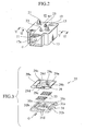
- the core portion 11 and the second side plate 15 are housed in a casing 17 shaped as a substantially rectangular box as shown in Fig. 2.
- the casing 17 is provided with an inflow port 17a and an outflow port 17b for circulation of reformed gas G.
- a flow direction of the reformed gas G is shown in Fig. 2.
- An upper end of the casing 17 is provided with a flange portion 17c with which the first side plate 13 is brazed.
- the first side plate 13 is provided with an inflow pipe 19 and an outflow pipe 21 for circulating cooling water W.
- the first side plate 13 is further provided with an air supply pipe 23 for supplying air from an outside thereof.
- the core portion 11 is provided with a first cooling membrane 25 and a plurality of second cooling membranes 27.
- the first cooling membrane 25 and the second cooling membranes 27 are accumulated with each other and cavities 41 are respectively held therebetween so that the reformed gas G can flow through the cavities 41.
- Two pairs of outer fins 37 sandwiching a pair of partition sheets 39 are disposed in the respective cavities 41.
- a pair of outer fins 37 are disposed under a lowest one of the second cooling membranes 27.
- the outer fins 37 are made of metal having high thermal conductivity such as aluminum.
- the outer fins 37 and the partition sheets 39 are coated by carbon monoxide oxidation catalyst, by which carbon monoxide contained in the reformed gas G is effectively oxidized.
- the first cooling membrane 25 is provided with a first sheet member 29, a second sheet member 31 and a plurality of inner fins 33 put therebetween as shown in Fig. 3.
- the first sheet member 29, the second sheet member 31 and the inner fins 33 are also made of metal having high thermal conductivity such as aluminum.
- the second sheet member 31 is provided with a collar portion 31a around a periphery thereof.
- the collar portion 31a is caulked to closely contact with a periphery of the first sheet member 29 so that the second sheet member 31 is fixed to the first sheet member 29.
- the first sheet member 29 is provided with a pair of inflated portions 29a projected toward the first side plate 13.
- One of the inflated portion 29a is provided with an inflow opening 29b, which the inflow pipe 19 is connected to and the cooling water W flows into.
- the other inflated portion 29a is provided with an outflow opening 29b which communicates with the outflow pipe 21 via a through hole 13b of the first side plate 13.
- the first sheet member 29 is further provided with air supply portions 29d extended in a direction orthogonal to the inflated portions 29a.
- One of the air supply portions 29d is disposed at a side of an air inflow side of the first sheet member 29 and the other air supply portion 29d is disposed at a medium of the first sheet member 29.
- the air supply portions 29d are respectively provided with inflow holes 29e so as to communicate with the air supply pipes 23.
- the second sheet member 31 is provided with a pair of inflated portions 31b projected toward the second side plate 15.
- the inflated portions 31b are respectively provided with communication holes 31c so as to communicate with an adjacent sheet 27.
- the second sheet member 31 is further provided with two rows of plural air outflow portions 31d.
- the two rows are disposed correspondingly to the air supply portions 29d of the first sheet member 29.
- Each of the second cooling membranes 27 is provided with a third sheet member 35, the second sheet member 31 and a plurality of the inner fins 33 put therebetween as shown in Fig. 4.
- the second sheet member 31 and the inner fins 33 are described above.
- the second sheet member 31 is fixed to the third sheet member 35 by caulking the collar portion 31a so as to closely contact with a periphery of the third sheet member 35.
- the third sheet member 35 is provided with a pair of inflated portions 35b projected toward the first side plate 13.
- the inflated portions 35b are respectively provided with communication holes 35c so as to communicate with the adjacent first or second cooling membrane 25 or 27.
- the third sheet member 35 is further provided with two rows of plural air inflow portions 35d.
- the two rows are disposed correspondingly to the outflow portions 31d of the adjacent second sheet member 31.
- the air outflow portions 31d and the air inflow portions 35d are respectively connected with each other via respective connection holes 43 as shown in Fig. 7.
- the air outflow portions 31d and the air inflow portions 35d are further provided with plural air injection holes 45 on both sides thereof.
- a pair of the inflated portion 29a and the inflated portion 31b and pairs of the inflated portions inflated portion 35b and the inflated portions 31b respectively form tank portions for supplying the cooling water W to the cooling membrane portions.
- the cooling water W from an outside flows into the core portion 11 through the inflow pipe 19 and first fills space between the inflated portions 29a, 31b, 35b as shown in Fig. 5.
- the cooling water W filling the space flows into the first cooling membrane 25 and the second cooling membranes 27.
- the cooling water W is collected to another space between the other inflated portions 29a, 31b, 35b on the other side and flows out through the outflow pipe 21.
- An air flow path for supplying the air A to cavities 41 formed between the respective sheets 25, 27, in which the outer fins 37 are disposed, is formed by the air supply portions 29d, the air outflow portions 31d, the air inflow portions 35d, the air injection holes 45 and the connection holes 43 communicating therewith.
- the air A which is supplied from the air supply pipe 23, first flows into the air supply portions 29d as shown in Fig. 6. The air A further flows through the air outflow portions 31d, 35d of the respective sheets 25, 27 and is supplied via the air injection holes 45 to the cavities 41.
- the members above described are installed with each other and housed in a heat treatment furnace so as to be brazed with each other.
- fluid of the carbon monoxide oxidation catalyst is infused into the cavities 41 so that the outer fins 37 and the partition sheets 39 are coated by the carbon monoxide oxidation catalyst.
- compressed air is supplied to the air supply portion 29d so as to remove excessive catalyst therein, which has a possibility of filling the air injection holes 45 and such. Thereby the heat exchanger with the catalyst is completed.
- the reformed gas G from a methanol reformer is conducted into the cavities 41 having outer fins 37 as shown in Fig. 8.
- the conducted reformed gas G is admixed with the air A containing oxygen, which is injected from the air injection holes 45, in the cavities 41.
- the reformed gas G mixed with the air A chemically react on surfaces of the carbon monoxide oxidation catalyst coated on the outer fins 37 and the partition sheets 39 so that carbon monoxide contained in the reformed gas G is effectively oxidized to carbon dioxide.
- the reformed gas G is effectively cooled by heat conduction of the outer fins 37 and the partition sheets 39 to the cooling water W, because the outer fins 37 and the partition sheets 39 are made of metal having high heat conductivity such as aluminum. Though the oxidation of the carbon monoxide is an exothermal reaction, temperature of the reformed gas G is effectively controlled and the oxidation reaction is effectively promoted.
- the present invention can be widely applied to heat exchangers with catalyst to which air is supplied from an outside thereof.
- the number of the rows of the inflow and outflow portions is limited to two, in the embodiment described above, the number can be one or, three or more.
- the sheets can be integrally formed from a metal sheet.
- air tanks for air supply to the sheets are applied instead of the inflated portions.
Landscapes
- Chemical & Material Sciences (AREA)
- Engineering & Computer Science (AREA)
- Chemical Kinetics & Catalysis (AREA)
- Organic Chemistry (AREA)
- Sustainable Development (AREA)
- General Chemical & Material Sciences (AREA)
- Mechanical Engineering (AREA)
- Thermal Sciences (AREA)
- Life Sciences & Earth Sciences (AREA)
- Manufacturing & Machinery (AREA)
- Physics & Mathematics (AREA)
- Sustainable Energy (AREA)
- Electrochemistry (AREA)
- General Engineering & Computer Science (AREA)
- Combustion & Propulsion (AREA)
- Inorganic Chemistry (AREA)
- Health & Medical Sciences (AREA)
- General Health & Medical Sciences (AREA)
- Hydrogen, Water And Hydrids (AREA)
- Fuel Cell (AREA)
- Heat-Exchange Devices With Radiators And Conduit Assemblies (AREA)
Abstract
Description
Claims (6)
- A heat exchanger with a catalyst, comprising:a plurality of cooling membrane portions for circulation of cooling water, being piled up and being communicated with each other;first tank portions respectively communicated with first ends of the cooling membrane portions, being communicated with each other;second tank portions respectively communicated with second ends of the cooling membrane portions , being communicated with each other;cavities respectively held between the cooling membrane portions so that a first gas flows through the cavities;a plurality of fins comprising catalyst supported thereon, the fins being disposed in the cavities; andan air flow path communicating with the cavities so as to supply a second gas to the cavities.
- The heat exchanger with the catalyst according to claim 1, wherein the air flow path comprises an air supply portions formed on the first sheet, one or more air outflow portions formed on the second sheets, one or more air inflow portions formed on the third sheets, one or more air injection holes formed on the air inflow portions and the air out flow portions.
- The heat exchanger with the catalyst according to claim 1, wherein the air inflow portions and the air outflow portions are disposed in one or more rows in a direction orthogonal to a flowing direction of the first gas on the cooling membrane portions.
- The heat exchanger with the catalyst according to claim 3, wherein the air inflow and outflow portions are disposed apart from each other in the rows.
- The heat exchanger with the catalyst according to claim 1, wherein the first gas is reformed gas containing carbon monoxide, the second gas is air and the catalyst is carbon monoxide oxidation catalyst.
- The heat exchanger with the catalyst according to claim 1, wherein the cooling membrane portions, the first tank portions, the second tank portions, the cavities and the air flow path are formed by a first sheet and a plurality of second and third sheets being piled up.
Applications Claiming Priority (2)
| Application Number | Priority Date | Filing Date | Title |
|---|---|---|---|
| JP2002088746A JP2003287386A (en) | 2002-03-27 | 2002-03-27 | Heat exchanger with catalyst |
| JP2002088746 | 2002-03-27 |
Publications (2)
| Publication Number | Publication Date |
|---|---|
| EP1348484A2 true EP1348484A2 (en) | 2003-10-01 |
| EP1348484A3 EP1348484A3 (en) | 2004-09-29 |
Family
ID=27800479
Family Applications (1)
| Application Number | Title | Priority Date | Filing Date |
|---|---|---|---|
| EP03007048A Withdrawn EP1348484A3 (en) | 2002-03-27 | 2003-03-27 | Heat Exchanger with Catalyst |
Country Status (3)
| Country | Link |
|---|---|
| US (1) | US20030217543A1 (en) |
| EP (1) | EP1348484A3 (en) |
| JP (1) | JP2003287386A (en) |
Cited By (5)
| Publication number | Priority date | Publication date | Assignee | Title |
|---|---|---|---|---|
| FR2936304A1 (en) * | 2008-09-25 | 2010-03-26 | Valeo Systemes Thermiques | HEAT EXCHANGE ELEMENT OF A HEAT EXCHANGE BEAM OF A HEAT EXCHANGER |
| WO2010066464A1 (en) * | 2008-12-12 | 2010-06-17 | Ezelleron Gmbh | Fuel cell system with reoxidation barrier |
| EP3138628A4 (en) * | 2014-08-29 | 2017-11-15 | IHI Corporation | Reactor |
| US10215496B2 (en) | 2013-02-19 | 2019-02-26 | Bosal Emission Control Systems Nv | Multi-flow heat exchanger for exchanging heat between cool fluid and hot fluid |
| CN114719638A (en) * | 2022-03-04 | 2022-07-08 | 杭州制氧机集团股份有限公司 | Plate-fin heat exchanger with built-in catalyst |
Families Citing this family (4)
| Publication number | Priority date | Publication date | Assignee | Title |
|---|---|---|---|---|
| JP4469674B2 (en) * | 2004-07-15 | 2010-05-26 | 株式会社東芝 | Manufacturing method of flow channel structure |
| WO2010040819A1 (en) * | 2008-10-10 | 2010-04-15 | Gambro Lundia Ab | Heat exchanger and method for heat exchanging |
| FR2974739B1 (en) * | 2011-05-03 | 2016-03-11 | Commissariat Energie Atomique | SOLID REACTOR MODULE / HEAT PUMP COMPRISING GAS DIFFUSERS WITH REDUCED SHUTDOWN HAZARDS |
| CN114165318B (en) * | 2021-12-09 | 2023-07-25 | 天津大学合肥创新发展研究院 | Integrated device inner core for recovering and post-treating waste heat of tail gas of internal combustion engine |
Family Cites Families (10)
| Publication number | Priority date | Publication date | Assignee | Title |
|---|---|---|---|---|
| AT362397B (en) * | 1976-10-13 | 1981-05-11 | Schober Robert Dipl Ing Dr Tec | DEVICE FOR INCREASING AMMONIA BUILDING IN CATALYTIC AMMONIA SYNTHESIS |
| US4973777A (en) * | 1985-11-08 | 1990-11-27 | Institut Francais Du Petrole | Process for thermally converting methane into hydrocarbons with higher molecular weights, reactor for implementing the process and process for realizing the reactor |
| FR2614615B1 (en) * | 1987-04-28 | 1989-08-04 | Inst Francais Du Petrole | PROCESS FOR THE THERMAL CONVERSION OF METHANE INTO HIGHER MOLECULAR WEIGHT HYDROCARBONS, REACTOR FOR IMPLEMENTING THE PROCESS AND METHOD FOR PRODUCING THE REACTOR |
| US5270127A (en) * | 1991-08-09 | 1993-12-14 | Ishikawajima-Harima Heavy Industries Co., Ltd. | Plate shift converter |
| TW216453B (en) * | 1992-07-08 | 1993-11-21 | Air Prod & Chem | Integrated plate-fin heat exchange reformation |
| DE19511817C2 (en) * | 1995-03-30 | 1997-10-09 | Aeg Energietechnik Gmbh | Plate-type heat exchanger with reformer |
| DE19539648C2 (en) * | 1995-10-25 | 1998-02-26 | Daimler Benz Ag | Reactor for selective CO oxidation in H¶2¶-rich gas |
| US5964280A (en) * | 1996-07-16 | 1999-10-12 | Modine Manufacturing Company | Multiple fluid path plate heat exchanger |
| JP3766016B2 (en) * | 2001-02-07 | 2006-04-12 | カルソニックカンセイ株式会社 | Fuel cell heat exchanger |
| SE520006C2 (en) * | 2001-09-20 | 2003-05-06 | Catator Ab | Device, method of manufacture and method of conducting catalytic reactions in plate heat exchangers |
-
2002
- 2002-03-27 JP JP2002088746A patent/JP2003287386A/en active Pending
-
2003
- 2003-03-26 US US10/396,694 patent/US20030217543A1/en not_active Abandoned
- 2003-03-27 EP EP03007048A patent/EP1348484A3/en not_active Withdrawn
Cited By (7)
| Publication number | Priority date | Publication date | Assignee | Title |
|---|---|---|---|---|
| FR2936304A1 (en) * | 2008-09-25 | 2010-03-26 | Valeo Systemes Thermiques | HEAT EXCHANGE ELEMENT OF A HEAT EXCHANGE BEAM OF A HEAT EXCHANGER |
| EP2169195A1 (en) * | 2008-09-25 | 2010-03-31 | Valeo Systemes Thermiques | Heat exchanging element of a heat exchange bundle in a heat exchanger |
| WO2010066464A1 (en) * | 2008-12-12 | 2010-06-17 | Ezelleron Gmbh | Fuel cell system with reoxidation barrier |
| US10215496B2 (en) | 2013-02-19 | 2019-02-26 | Bosal Emission Control Systems Nv | Multi-flow heat exchanger for exchanging heat between cool fluid and hot fluid |
| EP3138628A4 (en) * | 2014-08-29 | 2017-11-15 | IHI Corporation | Reactor |
| US10258961B2 (en) | 2014-08-29 | 2019-04-16 | Ihi Corporation | Reactor |
| CN114719638A (en) * | 2022-03-04 | 2022-07-08 | 杭州制氧机集团股份有限公司 | Plate-fin heat exchanger with built-in catalyst |
Also Published As
| Publication number | Publication date |
|---|---|
| JP2003287386A (en) | 2003-10-10 |
| EP1348484A3 (en) | 2004-09-29 |
| US20030217543A1 (en) | 2003-11-27 |
Similar Documents
| Publication | Publication Date | Title |
|---|---|---|
| JP3766016B2 (en) | Fuel cell heat exchanger | |
| JP2006505912A (en) | Heat exchanger | |
| EP1348484A2 (en) | Heat Exchanger with Catalyst | |
| JP4418358B2 (en) | Heat exchanger | |
| CA2587241A1 (en) | Device for carrying out a chemical reaction | |
| JP6504394B2 (en) | Heat exchanger, method of manufacturing heat exchanger, and fuel cell system | |
| JP4644892B2 (en) | Reformer | |
| US7104314B2 (en) | Multi-pass heat exchanger | |
| JP2008514536A (en) | Apparatus and method for selective oxidation of carbon monoxide | |
| JP2010027366A (en) | Fuel cell cogeneration system | |
| JP6242143B2 (en) | Combined heat exchange and fluid mixing device | |
| JP2005147480A (en) | Multi-fluid heat exchanger | |
| JP4416670B2 (en) | Multi-fluid heat exchanger | |
| US20210060520A1 (en) | Reactor | |
| JP2000319003A (en) | Fuel reformer and heat exchanger used for same | |
| JP4322519B2 (en) | Catalytic reactor | |
| JP2002293509A (en) | CO remover | |
| JP3695304B2 (en) | Carbon monoxide removal equipment | |
| JP2005047770A (en) | Heat exchanger for reformer | |
| JP2008204662A (en) | Fuel cell power generation system | |
| JP4412689B2 (en) | Fuel processor for fuel cell | |
| JP2002198078A (en) | Heat exchanger with catalyst for fuel cell | |
| CN120376687A (en) | Heat exchanger | |
| JP3741370B2 (en) | Heat exchange type catalytic reactor | |
| JP2008300157A (en) | Fuel cell unit |
Legal Events
| Date | Code | Title | Description |
|---|---|---|---|
| PUAI | Public reference made under article 153(3) epc to a published international application that has entered the european phase |
Free format text: ORIGINAL CODE: 0009012 |
|
| AK | Designated contracting states |
Kind code of ref document: A2 Designated state(s): AT BE BG CH CY CZ DE DK EE ES FI FR GB GR HU IE IT LI LU MC NL PT SE SI SK TR |
|
| AX | Request for extension of the european patent |
Extension state: AL LT LV MK RO |
|
| PUAL | Search report despatched |
Free format text: ORIGINAL CODE: 0009013 |
|
| AK | Designated contracting states |
Kind code of ref document: A3 Designated state(s): AT BE BG CH CY CZ DE DK EE ES FI FR GB GR HU IE IT LI LU MC NL PT SE SI SK TR |
|
| AX | Request for extension of the european patent |
Extension state: AL LT LV MK RO |
|
| 17P | Request for examination filed |
Effective date: 20050126 |
|
| AKX | Designation fees paid |
Designated state(s): DE FR GB |
|
| STAA | Information on the status of an ep patent application or granted ep patent |
Free format text: STATUS: THE APPLICATION IS DEEMED TO BE WITHDRAWN |
|
| 18D | Application deemed to be withdrawn |
Effective date: 20060823 |