EP1347677B1 - Improved self drive assembly for lawn mower - Google Patents
Improved self drive assembly for lawn mower Download PDFInfo
- Publication number
- EP1347677B1 EP1347677B1 EP01978006A EP01978006A EP1347677B1 EP 1347677 B1 EP1347677 B1 EP 1347677B1 EP 01978006 A EP01978006 A EP 01978006A EP 01978006 A EP01978006 A EP 01978006A EP 1347677 B1 EP1347677 B1 EP 1347677B1
- Authority
- EP
- European Patent Office
- Prior art keywords
- assembly
- drive
- axle
- gear box
- housing
- Prior art date
- Legal status (The legal status is an assumption and is not a legal conclusion. Google has not performed a legal analysis and makes no representation as to the accuracy of the status listed.)
- Expired - Lifetime
Links
Images




Classifications
-
- A—HUMAN NECESSITIES
- A01—AGRICULTURE; FORESTRY; ANIMAL HUSBANDRY; HUNTING; TRAPPING; FISHING
- A01D—HARVESTING; MOWING
- A01D34/00—Mowers; Mowing apparatus of harvesters
- A01D34/01—Mowers; Mowing apparatus of harvesters characterised by features relating to the type of cutting apparatus
- A01D34/412—Mowers; Mowing apparatus of harvesters characterised by features relating to the type of cutting apparatus having rotating cutters
- A01D34/63—Mowers; Mowing apparatus of harvesters characterised by features relating to the type of cutting apparatus having rotating cutters having cutters rotating about a vertical axis
- A01D34/67—Mowers; Mowing apparatus of harvesters characterised by features relating to the type of cutting apparatus having rotating cutters having cutters rotating about a vertical axis hand-guided by a walking operator
- A01D34/68—Mowers; Mowing apparatus of harvesters characterised by features relating to the type of cutting apparatus having rotating cutters having cutters rotating about a vertical axis hand-guided by a walking operator with motor driven cutters or wheels
- A01D34/69—Mowers; Mowing apparatus of harvesters characterised by features relating to the type of cutting apparatus having rotating cutters having cutters rotating about a vertical axis hand-guided by a walking operator with motor driven cutters or wheels with motor driven wheels
-
- A—HUMAN NECESSITIES
- A01—AGRICULTURE; FORESTRY; ANIMAL HUSBANDRY; HUNTING; TRAPPING; FISHING
- A01D—HARVESTING; MOWING
- A01D2101/00—Lawn-mowers
Definitions
- the present invention relates to self drive lawn mowers, as disclosed in US-A-4915203 , and more particularly relates to an improved self drive assembly for attachment to mowers of the walk behind push variety and which are capable of conversion between a self drive state and a manual state.
- a known mower self drive assembly comprises a gear box mounted on an axle, an input arm on said gear box which takes power from a drive motor via a drive belt, an output connected to the gear box which engages a cog wheel mounted on a wheel hub, such that when the motor of the mower is running, the drive belt transfers engine power to the gear box via the input whereupon the gear box transfers drive to an output which turns the rear wheels of the mower via interengaging cogs.
- the present invention seeks to ameliorate the problems associated with the known self drive assemblies by providing an alternative assembly which provides efficient self drive but without obstruction of the chute opening to the grass catcher and unwanted clogging of the grass catcher chute opening.
- the present invention comprises a self drive assembly for a walk behind lawn mower according to claim 1.
- the present invention comprises a walk behind lawn mower according to claim 12.
- the present invention comprises a method according to claim 24.
- FIG. 1 there is shown a rear perspective view of a prior art mower housing 1 including a rear opening 2 which allows passage of grass delivered from a cutter deck within housing 1 to a grass catcher (not shown) having a corresponding entry opening which opposes opening 2.
- Housing 1 further comprises a self drive assembly 3 mounted on rear wheel axle 4.
- Self drive assembly 2 engages a motor which would normally be located in the region indicated by arrow 5 and by indirect transmission to axle 4 imparts self drive to the mower when axle 4 is caused to rotate.
- Ground engaging wheels normally located (but not shown) at ends 6 and 7 of axle 4 and driven by axle 4 self drive the mower.
- Self drive assembly 3 includes gear box 8 directly connected to axle 4 so that direct self drive is imparted to the wheels.
- the location of gear box 8 significantly reduces the area of opening 2 available to deliver grass from the cutter deck to the grass catcher.
- opening 2 bounded and defined by walls 9 and 10 and roof 11 represents the potential opening area available to receive grass from the cutter deck into the grass catcher but this is significantly reduced in area by the location and configuration of self drive assembly 3.
- the configuration of the known self drive assemblies have traditionally involved a compromise between the advantages of including the self drive feature and the resultant restriction to the remaining opening space available to receive cut grass.
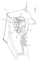
- FIG. 2 shows a cutter deck housing 20 of a walk behind mower with self drive assembly 21 connected thereto according to one embodiment of the invention.
- Housing 20 includes opening 22 which allows passage of grass delivered from a cutter deck within housing 20 to a grass catcher (not shown) having an entry opening which opposes opening 22.
- Drive assembly 21 engages a motor which communicates with engine pulley 29 and further includes gear box 27 which is located at a predetermined clearance above axle 28 so that direct self drive is imparted to the wheels which would be fitted to ends 28a and 28b.
- the location of the gear box 27 significantly increases the available area of opening 22 available to receive grass from a grass catcher which opposes opening 22.
- Opening 22 which is bounded and defined by walls 23 and 24 and roof 25 represents the potential opening area available to receive grass from a grass catcher. Opening 22 is substantially free of obstruction and is significantly increased in area of grass delivery to a grass catcher compared to the available area remaining after subtracting the area taken up by self drive assembly 3 illustrated in Figure 1. The configuration of that assembly would if the prior art self drive assembly was used cause a substantial reduction of up to 30-40% of the area of opening 22 and a resultant decrease in the rate and efficiency of grass catching for a mower of a given size. With self drive assembly 21 installed on housing 20 the area of opening 22 available to receive grass from a grass catcher is increased to an extent that almost all opening 22 is available to allow passage of cut grass.
- the only obstruction of opening 22 is casing 26 which comprises a drive belt or chain transmitting drive from gear box 27 to axle 28.
- Axle 28 receives wheels (not shown) on ends 28a and 28b.
- Casing 26 takes up only a small portion of opening 22 leaving opening 22 substantially free of obstruction so all available area in opening 22 is dedicated to allowing passage of grass. This has the advantage that an increased volume of grass can be delivered through opening 22 by a cutter deck for the same size mower.
- the alternative configuration of self drive assembly 21 renders the opening substantially free of obstruction thereby minimising the risk of unwanted clogging of opening 22 with grass clippings.
- Casing 26 may be integral with wall 23 or a separate component attached thereto. Casing 26 also prevents fouling of output assembly components to be described below.
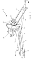
- FIG 3 there is shown a perspective view of a self drive assembly 30 according to a preferred embodiment for attachment to a mower of the walk behind type.
- Assembly 30 which has been exploded from a mower housing (not shown for clarity) is viewed from a side frontal direction.
- Assembly 30 includes a gear box 31 which transmits drive from a motor via a clutch to a drive axle. Power from a drive motor is transferred to drive pulley 32 which drives belt 33. Belt 33 also engages input pulley 34 which is connected to input shaft 35 which terminates at gear box 31.
- Gear box 31 is operably linked to output clutch 36 disposed in a generally vertical plane and which receives drive belt or chain 37.
- Output clutch 36 is directly connected to gear box 31 via output shaft 38 and includes sprocket 39 which receives drive chain 37.
- Drive chain 37 is connected to axle 40 via sprocket 41 such that rotation of output clutch 36 responsive to drive imparted from a motor via input pulley 34 and input shaft 35 to gear box 31 causes axle 40 to rotate thereby imparting drive to wheels (not shown) mounted on ends 40a and 40b of axle 40 of the lawn mower to which the drive assembly is attached.
- Self drive assembly 30 as shown, is located above axle 40 at a height which comfortably clears axle 40 and minimises or eliminates obstruction by gear box 31 of an opening in a mower housing which in the arrangement shown in figure 3 would be on the left side of gear box 31 and allows passage of grass cut by the mower for delivery to a grass catcher.
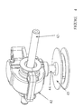
- gear box 42 includes output shaft 43 and input shaft 44.
- Input shaft 44 receives input pulley 45 which is driven by a motor on a lawn mower.
- Shaft 43 receives a sprocket which receives a chain which transfers drive from shaft 43 to a wheel axle in the same manner as that described with reference to figure 3.
- Gear box 42 as with the other gear boxes described in this specification receives input drive from a motor via a downwardly depending shaft such as shaft 44 as shown in figure 4.
- Figure 5 shows the self drive assembly of figure 4 including housings 47 and 48.
- Housing 48 accommodates the output assembly which includes output clutch 49 and sprocket 50.
- clutch 49 is covered and this also protects the drive belt or chain driven by the sprocket.
- Figure 6 shows the assembly of figure 5 with clutch 49 and sprocket 50 protected by cover component 51.
- Figure 7 shows the self drive assembly fully assembled and installed on mower housing 52. It can be seen from the front perspective view in figure 7 that assembly 53 is arranged such that all components of the assembly 53 except for the transmission belt 37 (see figure 3) and casing 26 (see figure 2) are above shaft 54 and above cutter deck cowling 55. This allows almost unobstructed passage of grass through an opening in the rear of housing 52 to a grass catcher or in the event of non use of a grass catcher to the outside of housing 52.
Landscapes
- Life Sciences & Earth Sciences (AREA)
- Environmental Sciences (AREA)
- Harvester Elements (AREA)
Description
- The present invention relates to self drive lawn mowers, as disclosed in
US-A-4915203 , and more particularly relates to an improved self drive assembly for attachment to mowers of the walk behind push variety and which are capable of conversion between a self drive state and a manual state. - There are in existence a wide variety of self drive lawn mowers which require manual engagement and disengagement of a drive assembly by an operator walking behind the mower. The known self drive assemblies operate by taking power from the engine and transferring drive to the rear wheels of the mower.
- By way of example, a known mower self drive assembly comprises a gear box mounted on an axle, an input arm on said gear box which takes power from a drive motor via a drive belt, an output connected to the gear box which engages a cog wheel mounted on a wheel hub, such that when the motor of the mower is running, the drive belt transfers engine power to the gear box via the input whereupon the gear box transfers drive to an output which turns the rear wheels of the mower via interengaging cogs. Although the known self drive mowers operate adequately to drive the mower, they suffer from a number of attendant disadvantages arising from the configuration of the drive assembly and its location relative to the opening to the grass catcher. In the known arrangements the gear box and drive arrangements partially obstruct the passage of grass delivered from the cutting blades to the grass catcher. This can cause clogging of the opening to the catcher and in serious cases particularly where the grass is wet, eventual stalling of the motor. Due to the physical size of conventional push type mowers and the limited space available in the cutting deck housing, designs thus far have not overcome the problem of obstruction of the grass catcher by the self drive assembly.
- The present invention seeks to ameliorate the problems associated with the known self drive assemblies by providing an alternative assembly which provides efficient self drive but without obstruction of the chute opening to the grass catcher and unwanted clogging of the grass catcher chute opening.
- In its broadest form the present invention comprises a self drive assembly for a walk behind lawn mower according to
claim 1. - Prefered embodiments are set out in the dependent claims 2-11.
- In another broad form the present invention comprises a walk behind lawn mower according to
claim 12. - Preferred embodiments are set out in the dependent claims 13-23.
- In another broad form of the method aspect the present invention comprises a method according to
claim 24. - The present invention will now be described in more detail according to a preferred but non limiting embodiment and with reference to the accompanying illustrations wherein:
- Figure I
- shows a perspective rear view of a mower housing and self drive assembly according to a prior art arrangement.
- Figure 2
- shows a perspective view of a self drive assembly according to a preferred embodiment of the invention; and
- Figure 3
- shows the drive assembly of figure 2 adapted to a mower and incorporated in a housing.
- Figure 4
- shows a perspective view of a gear box of a self drive assembly according to a preferred embodiment of the invention.
- Figure 5
- shows a perspective view of the gear box arrangement of figure 4 incorporated with drive assembly protective housings.
- Figure 6
- shows the assembly of figure 5 with a clutch and sprocket protected by cover component.
- Figure 7
- shows the self drive assembly fully assembled and installed on a mower housing from a front perspective view.
- Traditional walk behind self drive lawn mowers comprise a motor which drives a cutting deck. The cutting deck is protected by a housing which defines an underside space in which grass is cut and which exits the housing under energy imparted by cutting blades through a rear opening. Prior art self drive lawn mowers include a self drive assembly which unfortunately due to its configuration and location has caused obstruction to the rear opening in the housing compromising efficient discharge of cut grass through the rear discharge opening. Referring to figure I there is shown a rear perspective view of a prior
art mower housing 1 including arear opening 2 which allows passage of grass delivered from a cutter deck withinhousing 1 to a grass catcher (not shown) having a corresponding entry opening which opposesopening 2.Housing 1 further comprises aself drive assembly 3 mounted onrear wheel axle 4. -
Self drive assembly 2 engages a motor which would normally be located in the region indicated byarrow 5 and by indirect transmission toaxle 4 imparts self drive to the mower whenaxle 4 is caused to rotate. Ground engaging wheels normally located (but not shown) atends axle 4 and driven byaxle 4 self drive the mower. -
Self drive assembly 3 includesgear box 8 directly connected toaxle 4 so that direct self drive is imparted to the wheels. The location ofgear box 8 significantly reduces the area ofopening 2 available to deliver grass from the cutter deck to the grass catcher. Thus, opening 2 bounded and defined bywalls roof 11 represents the potential opening area available to receive grass from the cutter deck into the grass catcher but this is significantly reduced in area by the location and configuration ofself drive assembly 3. The configuration of the known self drive assemblies have traditionally involved a compromise between the advantages of including the self drive feature and the resultant restriction to the remaining opening space available to receive cut grass. The inclusion of the self drive arrangement as shown in figure 1 necessitates a substantial reduction of up to 30-40% of the area of opening 2 and a resultant decrease in the rate and efficiency of grass catching for a mower of a given size cutter deck. This results in an available opening defined byroof 11wall 10 andpartition 12. There has been a long felt want in the mower industry to provide a self drive mower of the walk behind type which includes a self drive assembly installed without compromise to the maximum available opening area in a housing through which cut grass may pass. The higher the area of the grass discharge opening the more efficient the mower.Gear box 8 ofdrive assembly 3 unavoidably takes up the space defined byroof 11wall 9 andpartition 12 as there is direct drive betweengear box 8 andaxle 4 which dictates gear box proximity toaxle 4. - Figure 2 shows a
cutter deck housing 20 of a walk behind mower withself drive assembly 21 connected thereto according to one embodiment of the invention.Housing 20 includes opening 22 which allows passage of grass delivered from a cutter deck withinhousing 20 to a grass catcher (not shown) having an entry opening which opposes opening 22.Drive assembly 21 engages a motor which communicates withengine pulley 29 and further includesgear box 27 which is located at a predetermined clearance aboveaxle 28 so that direct self drive is imparted to the wheels which would be fitted toends gear box 27 significantly increases the available area of opening 22 available to receive grass from a grass catcher which opposes opening 22. -
Opening 22 which is bounded and defined bywalls roof 25 represents the potential opening area available to receive grass from a grass catcher.Opening 22 is substantially free of obstruction and is significantly increased in area of grass delivery to a grass catcher compared to the available area remaining after subtracting the area taken up byself drive assembly 3 illustrated in Figure 1. The configuration of that assembly would if the prior art self drive assembly was used cause a substantial reduction of up to 30-40% of the area of opening 22 and a resultant decrease in the rate and efficiency of grass catching for a mower of a given size. Withself drive assembly 21 installed onhousing 20 the area of opening 22 available to receive grass from a grass catcher is increased to an extent that almost all opening 22 is available to allow passage of cut grass. The only obstruction of opening 22 iscasing 26 which comprises a drive belt or chain transmitting drive fromgear box 27 toaxle 28.Axle 28 receives wheels (not shown) onends Casing 26 takes up only a small portion of opening 22 leaving opening 22 substantially free of obstruction so all available area in opening 22 is dedicated to allowing passage of grass. This has the advantage that an increased volume of grass can be delivered through opening 22 by a cutter deck for the same size mower. Compared to the known self drive assemblies, the alternative configuration ofself drive assembly 21 renders the opening substantially free of obstruction thereby minimising the risk of unwanted clogging of opening 22 with grass clippings.Casing 26 may be integral withwall 23 or a separate component attached thereto.Casing 26 also prevents fouling of output assembly components to be described below. - Referring to figure 3 there is shown a perspective view of a
self drive assembly 30 according to a preferred embodiment for attachment to a mower of the walk behind type.Assembly 30 which has been exploded from a mower housing (not shown for clarity) is viewed from a side frontal direction.Assembly 30 includes agear box 31 which transmits drive from a motor via a clutch to a drive axle. Power from a drive motor is transferred to drivepulley 32 which drivesbelt 33.Belt 33 also engagesinput pulley 34 which is connected to inputshaft 35 which terminates atgear box 31.Gear box 31 is operably linked tooutput clutch 36 disposed in a generally vertical plane and which receives drive belt orchain 37.Output clutch 36 is directly connected togear box 31 viaoutput shaft 38 and includessprocket 39 which receivesdrive chain 37.Drive chain 37 is connected toaxle 40 viasprocket 41 such that rotation of output clutch 36 responsive to drive imparted from a motor viainput pulley 34 andinput shaft 35 togear box 31causes axle 40 to rotate thereby imparting drive to wheels (not shown) mounted onends 40a and 40b ofaxle 40 of the lawn mower to which the drive assembly is attached.Self drive assembly 30 as shown, is located aboveaxle 40 at a height which comfortably clearsaxle 40 and minimises or eliminates obstruction bygear box 31 of an opening in a mower housing which in the arrangement shown in figure 3 would be on the left side ofgear box 31 and allows passage of grass cut by the mower for delivery to a grass catcher. Various alternatives may be employed in theself drive assembly 30 including substitution of a belt forchain 37 and replacement ofsprockets gear box 42 from a self drive assembly according to a preferred embodiment of the invention.Gear box 42 includesoutput shaft 43 andinput shaft 44.Input shaft 44 receivesinput pulley 45 which is driven by a motor on a lawn mower.Shaft 43 receives a sprocket which receives a chain which transfers drive fromshaft 43 to a wheel axle in the same manner as that described with reference to figure 3.Gear box 42 as with the other gear boxes described in this specification receives input drive from a motor via a downwardly depending shaft such asshaft 44 as shown in figure 4. - Figure 5 shows the self drive assembly of figure 4 including
housings Housing 48 accommodates the output assembly which includesoutput clutch 49 andsprocket 50. In use, clutch 49 is covered and this also protects the drive belt or chain driven by the sprocket. - Figure 6 shows the assembly of figure 5 with
clutch 49 andsprocket 50 protected by cover component 51. - Figure 7 shows the self drive assembly fully assembled and installed on
mower housing 52. It can be seen from the front perspective view in figure 7 thatassembly 53 is arranged such that all components of theassembly 53 except for the transmission belt 37 (see figure 3) and casing 26 (see figure 2) are aboveshaft 54 and abovecutter deck cowling 55. This allows almost unobstructed passage of grass through an opening in the rear ofhousing 52 to a grass catcher or in the event of non use of a grass catcher to the outside ofhousing 52.
Claims (25)
- A self drive assembly (21) for a walk behind lawn mower of the type including a motor for driving a cutting deck, front and rear wheels supporting a housing (20) for said cutter deck, the housing (20) including a rear opening (22) which allows passage therethrough of grass delivered from said cutting deck into a grass catcher which detachably engages said housing (20) and opposes said opening (22) the self drive assembly (21) including; a gear box (27) including an input (34, 35) connected to an output (32) of said motor; an output assembly (38) connected to said gear box (27) which drives a rear axle (28) at whose ends said rear wheels are connected, means (36) for engaging and disengaging said drive assembly (21) such that when the drive assembly (21) is engaged said mower is self propelled and when the assembly (21) is disengaged said mower is manually operable; characterized in that the self drive assembly (21) is mounted on the mower such that said transmission / gear box (27) is located forward of and elevated above said rear wheel axle (28) to maximise the area defined by said rear opening (22) available to discharge grass from said cutting deck to said grass catcher; and wherein said output assembly (38) transfers drive to said axle (28) at a single contact location on said axle (28) adjacent one of said rear wheels
- An assembly (21) according to claim 1 wherein said rear opening (22) is defined by side walls (23,24) and a roof of said housing (20),
- An assembly (21) according to claim 2 wherein said output assembly (21) is disposed in a housing (26) which lies adjacent one said side walls(23,24).
- An assembly (21) according to claim 3 wherein said housing (26) is integral with said side wall (23).
- An assembly (21) according to claim 4 wherein said self drive assembly (21) is configured to allow clear passage of said grass through up to 95% of the area of said rear opening (22).
- An assembly (21) according to claim 5 wherein the output assembly (38) includes drive means for communicating between said gear box (27) and a drive pulley (37) which engages said axle (28,40).
- An assembly (21) according to claim 6 wherein, said output assembly (38) includes a drive pulley (37) adjacent said gear box (31).
- An assembly (21) according to claim 7 wherein said pulley (37) on said rear axle (28,40) includes a sprocket (41) on said rear axle (28, 40),
- An assembly (21) according to claim 8 wherein said drive means to said axle (28, 40) is imparted from said gear box (31) via a drive chain (37) which engages the sprocket (41) on said shaft (40).
- An assembly (21) according to claim 8 wherein drive to said axle (40) is imparted from said gear box (31) via a drive belt (37) which engages said sprocket (41) on said shaft (40).
- An assembly (21) according to claim 9 or 10 wherein said drive belt or chain (37) engages via a first end a clutch (36) operably linked to said gear box (31), the clutch (36) including a sprocket or pulley which imparts drive via said belt or chain (37) to said axle (40)
- A lawn mower of the type including a motor for driving a cutting deck, front and rear wheels supporting a housing (20) for said cutter deck, the housing (20) including a rear opening (22) which, allows passage therethrough of grass delivered from said cutting deck into a grass catcher which detachably engages said housing (20) and opposes said opening, (22) the mower further including a self drive assembly, (21) wherein the self drive assembly (21) includes;a gear box (27) including an input (34,35) operably connected to an output (32) of said motor;an output assembly (38) connected to said gear box (27) which drives a wheel axle (28) of said mower, means (36) for engaging and disengaging said drive assembly (21) such that when the drive assembly (21) is engaged said mower is self propelled and when the assembly (21) is disengaged said mower is manually operable; characterized in thatthe self drive assembly (21) is mounted on the mower such that said transmission gear box (27) is located forward of and elevated above said rear wheel axle (28) to maximise the area defined by said rear opening (22) available to discharge grass from said outting deck to said grass catcher; and wherein said output assembly (38) transfers drive to said axle (28) at a single contact location on said axle (28) adjacent one of said rear wheels
- A lawn mower according to claim 12 wherein said rear opening (22) is defined by side walls (23,24) and a roof of said housing (20).
- A lawn mower according to claim 13 wherein said output assembly (21), is disposed in a housing (26) which lies adjacent one said side walls (23).
- A lawn mower according to claim 14 wherein said housing (26) is integral with said side walls (23).
- A lawn mower according to claim 15 wherein said self drive assembly is configured to allow clear passage of said grass through up to 95% of the area of said rear opening (22).
- A lawn mower according to claim 16 wherein the output assembly (38) includes drive means for communicating between said gear box (27) and a drive pulley (37) which engages said axle (28, 40).
- A lawn mower according to claim 17 wherein, said output assembly (38) includes a drive pulley (37) adjacent said gear box (31)
- A lawn mower according to claim 18 wherein said pulley (37) on said rear axle (28, 40) includes a sprocket (41) on said rear axle (28, 40)
- A lawn mower according to claim 19 wherein said drive means to said axle (28,40) is imparted from said gear box (31) via a drive chain (37) which engages the sprocket (41) on said shaft (40).
- A lawn mower according to claim 19 wherein drive to said axle (40) is imparted from said gear box (31) via a drive belt (37) which engages said sprocket (41) on said shaft (40).
- A lawn mower according to claim 20 or 21 wherein said drive belt or chain (37) engages via a first end a clutch (36) operably linked to said gear box (31), the clutch (36) including a sprocket or pulley which imparts drive via said belt or chain (37) to said axle (40).
- A lawn mower according to claim 22 wherein a drive pulley and belt or chain (37) drives said rear axle (40) when said self drive assembly (21) is actuated.
- A method of a constructing of a drive assembly (21) for a self drive lawn mower, of the type including a motor for driving a cutting deck, front and rear wheels supporting a housing (20) for said cutter deck, the housing (20) including a rear openings (22) which allows passage therethrough of grass delivered from said cutting deck into a grass catcher which detachably engages said housing (20) and opposes said opening (22) the method comprising the steps of;a) taking a gear box (27) having an input (34,35) and an output (38)b) attaching a clutch (36) to said output (38) of said gear box (27)c) attaching a pulley (33) to said input (34,35) of said gear box (27) ;d) providing a link (32) between said pulley (33) and said drive motor;e) providing a link (37) between said clutch (36) and an axle of said mower (40)f) providing means for engaging and disengaging said drive assembly such that when the drive assembly (21) is engaged said mower is self propelled and when the assembly (21) lis disengaged said mower is manually operable;g) locating said drive assembly (21) on said mower such that said gear box (27) is located above and forward of said wheel axle to maximise the area defined by said rear opening (22) available to receive grass from said cutting deck to said grass catcher.
- A method according to claim 24 wherein said gear box (27) and clutch (36) are located above said wheel axle (40) with sufficient clearance to maximize the area of said rear opening (22) which will allow grass to pass after cutting by said cutting deck.
Applications Claiming Priority (3)
| Application Number | Priority Date | Filing Date | Title |
|---|---|---|---|
| AUPR0998A AUPR099800A0 (en) | 2000-10-24 | 2000-10-24 | Improvements in self drive assembly for lawn mowers |
| AUPR099800 | 2000-10-24 | ||
| PCT/AU2001/001355 WO2002034028A1 (en) | 2000-10-24 | 2001-10-24 | Improved self drive assembly for lawn mower |
Publications (3)
| Publication Number | Publication Date |
|---|---|
| EP1347677A1 EP1347677A1 (en) | 2003-10-01 |
| EP1347677A4 EP1347677A4 (en) | 2006-07-26 |
| EP1347677B1 true EP1347677B1 (en) | 2007-09-12 |
Family
ID=3825045
Family Applications (1)
| Application Number | Title | Priority Date | Filing Date |
|---|---|---|---|
| EP01978006A Expired - Lifetime EP1347677B1 (en) | 2000-10-24 | 2001-10-24 | Improved self drive assembly for lawn mower |
Country Status (4)
| Country | Link |
|---|---|
| EP (1) | EP1347677B1 (en) |
| AU (2) | AUPR099800A0 (en) |
| GB (1) | GB2383935B (en) |
| WO (1) | WO2002034028A1 (en) |
Families Citing this family (1)
| Publication number | Priority date | Publication date | Assignee | Title |
|---|---|---|---|---|
| NZ570911A (en) | 2008-08-29 | 2010-01-29 | Masport Ltd | A lawn mower with a shredder blade feed by a tube that passes through the belt sending power to the rear wheels |
Family Cites Families (10)
| Publication number | Priority date | Publication date | Assignee | Title |
|---|---|---|---|---|
| US4038883A (en) * | 1975-09-10 | 1977-08-02 | The J. B. Foote Foundry Co. | Compact transmission |
| US4117652A (en) * | 1976-09-30 | 1978-10-03 | The J. B. Foote Foundry Co. | Transmission for self-propelled, walking lawn mowers |
| US4146105A (en) * | 1977-05-13 | 1979-03-27 | Wisconsin Marine, Inc. | Lawn mower |
| US4214641A (en) * | 1978-06-14 | 1980-07-29 | The J. B. Foote Foundry Co. | Drive for self-propelled lawn mowers |
| US4785612A (en) * | 1987-07-24 | 1988-11-22 | Yamaha Hatsudoki Kabushiki Kaisha | Walk-behind lawn mower |
| IT1250727B (en) * | 1991-07-31 | 1995-04-21 | Castel Garden Equip | MOWER TRACTOR FOR THE MAINTENANCE OF GRASS |
| JPH08130960A (en) * | 1994-11-04 | 1996-05-28 | Kubota Corp | Walking mower |
| JP3263707B2 (en) * | 1995-11-10 | 2002-03-11 | 株式会社 神崎高級工機製作所 | Transmission of walking type self-propelled lawn mower |
| US5718105A (en) * | 1996-01-03 | 1998-02-17 | Kanzaki Kokyukoki Mfg. Co., Ltd. | Transmission for self-propelled walking lawn mower |
| JPH09220012A (en) * | 1996-02-15 | 1997-08-26 | Kanzaki Kokyukoki Mfg Co Ltd | Transmission for self-running lawn mower |
-
2000
- 2000-10-24 AU AUPR0998A patent/AUPR099800A0/en not_active Abandoned
-
2001
- 2001-01-24 AU AU1027002A patent/AU1027002A/en not_active Withdrawn
- 2001-10-24 WO PCT/AU2001/001355 patent/WO2002034028A1/en not_active Ceased
- 2001-10-24 EP EP01978006A patent/EP1347677B1/en not_active Expired - Lifetime
- 2001-10-24 GB GB0309178A patent/GB2383935B/en not_active Expired - Fee Related
Also Published As
| Publication number | Publication date |
|---|---|
| EP1347677A1 (en) | 2003-10-01 |
| GB0309178D0 (en) | 2003-05-28 |
| EP1347677A4 (en) | 2006-07-26 |
| WO2002034028A1 (en) | 2002-05-02 |
| GB2383935A (en) | 2003-07-16 |
| GB2383935B (en) | 2004-05-26 |
| AU1027002A (en) | 2002-05-06 |
| AUPR099800A0 (en) | 2000-11-16 |
Similar Documents
| Publication | Publication Date | Title |
|---|---|---|
| US6192666B1 (en) | Lawn mower | |
| AU2002301225B2 (en) | Lawn mower | |
| EP0300383B1 (en) | Walk-behind lawn mower | |
| EP1632123B1 (en) | Lawn mower | |
| WO2019049045A1 (en) | Dual blade walk-behind mower | |
| EP1637028B1 (en) | Lawn mower | |
| US4716717A (en) | Power lawn mower | |
| US8056306B2 (en) | Rear discharge mower | |
| EP2172094B1 (en) | Lawn mower | |
| WO2002034028A1 (en) | Improved self drive assembly for lawn mower | |
| AU2002210270A1 (en) | Improved self drive assembly for lawn mower | |
| AU2007200377B2 (en) | Improved Self Drive Assembly For Lawn Mowers | |
| US7302791B2 (en) | Lawn mower | |
| JP2001251924A (en) | Blade mower mower deck | |
| JP7357598B2 (en) | work vehicle | |
| KR200214979Y1 (en) | Pasture harvester | |
| JP3406170B2 (en) | Riding mower | |
| JP2003158907A (en) | Riding lawn mower | |
| US2861411A (en) | Rotary reel mower | |
| JPH08130960A (en) | Walking mower | |
| JPH0319688Y2 (en) | ||
| CN2489569Y (en) | Small front-suspension rotary mower | |
| KR200205075Y1 (en) | Corn harvester | |
| US20030019198A1 (en) | Tiller tine mower | |
| EP0840998A3 (en) | Land mower with frontal plate-like mowing assembly |
Legal Events
| Date | Code | Title | Description |
|---|---|---|---|
| PUAI | Public reference made under article 153(3) epc to a published international application that has entered the european phase |
Free format text: ORIGINAL CODE: 0009012 |
|
| 17P | Request for examination filed |
Effective date: 20030526 |
|
| AK | Designated contracting states |
Kind code of ref document: A1 Designated state(s): AT BE CH CY DE DK ES FI FR GB GR IE IT LI LU MC NL PT SE TR |
|
| AX | Request for extension of the european patent |
Extension state: AL LT LV MK RO SI |
|
| RBV | Designated contracting states (corrected) |
Designated state(s): BE IE |
|
| REG | Reference to a national code |
Ref country code: DE Ref legal event code: 8566 |
|
| A4 | Supplementary search report drawn up and despatched |
Effective date: 20060622 |
|
| GRAP | Despatch of communication of intention to grant a patent |
Free format text: ORIGINAL CODE: EPIDOSNIGR1 |
|
| GRAS | Grant fee paid |
Free format text: ORIGINAL CODE: EPIDOSNIGR3 |
|
| GRAA | (expected) grant |
Free format text: ORIGINAL CODE: 0009210 |
|
| AK | Designated contracting states |
Kind code of ref document: B1 Designated state(s): BE IE |
|
| REG | Reference to a national code |
Ref country code: IE Ref legal event code: FG4D |
|
| PLBE | No opposition filed within time limit |
Free format text: ORIGINAL CODE: 0009261 |
|
| STAA | Information on the status of an ep patent application or granted ep patent |
Free format text: STATUS: NO OPPOSITION FILED WITHIN TIME LIMIT |
|
| 26N | No opposition filed |
Effective date: 20080613 |
|
| PGFP | Annual fee paid to national office [announced via postgrant information from national office to epo] |
Ref country code: IE Payment date: 20091027 Year of fee payment: 9 |
|
| PGFP | Annual fee paid to national office [announced via postgrant information from national office to epo] |
Ref country code: BE Payment date: 20091117 Year of fee payment: 9 |
|
| BERE | Be: lapsed |
Owner name: ROVER MOWERS LTD Effective date: 20101031 |
|
| PG25 | Lapsed in a contracting state [announced via postgrant information from national office to epo] |
Ref country code: BE Free format text: LAPSE BECAUSE OF NON-PAYMENT OF DUE FEES Effective date: 20101031 |
|
| PG25 | Lapsed in a contracting state [announced via postgrant information from national office to epo] |
Ref country code: IE Free format text: LAPSE BECAUSE OF NON-PAYMENT OF DUE FEES Effective date: 20101025 |