EP1347636A2 - A scannerless range imaging system having high dynamic range - Google Patents
A scannerless range imaging system having high dynamic range Download PDFInfo
- Publication number
- EP1347636A2 EP1347636A2 EP03075686A EP03075686A EP1347636A2 EP 1347636 A2 EP1347636 A2 EP 1347636A2 EP 03075686 A EP03075686 A EP 03075686A EP 03075686 A EP03075686 A EP 03075686A EP 1347636 A2 EP1347636 A2 EP 1347636A2
- Authority
- EP
- European Patent Office
- Prior art keywords
- range
- image
- imaging system
- transmittance
- pixel
- Prior art date
- Legal status (The legal status is an assumption and is not a legal conclusion. Google has not performed a legal analysis and makes no representation as to the accuracy of the status listed.)
- Withdrawn
Links
Images



Classifications
-
- G—PHYSICS
- G01—MEASURING; TESTING
- G01S—RADIO DIRECTION-FINDING; RADIO NAVIGATION; DETERMINING DISTANCE OR VELOCITY BY USE OF RADIO WAVES; LOCATING OR PRESENCE-DETECTING BY USE OF THE REFLECTION OR RERADIATION OF RADIO WAVES; ANALOGOUS ARRANGEMENTS USING OTHER WAVES
- G01S7/00—Details of systems according to groups G01S13/00, G01S15/00, G01S17/00
- G01S7/48—Details of systems according to groups G01S13/00, G01S15/00, G01S17/00 of systems according to group G01S17/00
- G01S7/491—Details of non-pulse systems
- G01S7/4912—Receivers
- G01S7/4915—Time delay measurement, e.g. operational details for pixel components; Phase measurement
-
- G—PHYSICS
- G01—MEASURING; TESTING
- G01S—RADIO DIRECTION-FINDING; RADIO NAVIGATION; DETERMINING DISTANCE OR VELOCITY BY USE OF RADIO WAVES; LOCATING OR PRESENCE-DETECTING BY USE OF THE REFLECTION OR RERADIATION OF RADIO WAVES; ANALOGOUS ARRANGEMENTS USING OTHER WAVES
- G01S17/00—Systems using the reflection or reradiation of electromagnetic waves other than radio waves, e.g. lidar systems
- G01S17/02—Systems using the reflection of electromagnetic waves other than radio waves
- G01S17/06—Systems determining position data of a target
- G01S17/08—Systems determining position data of a target for measuring distance only
- G01S17/32—Systems determining position data of a target for measuring distance only using transmission of continuous waves, whether amplitude-, frequency-, or phase-modulated, or unmodulated
- G01S17/36—Systems determining position data of a target for measuring distance only using transmission of continuous waves, whether amplitude-, frequency-, or phase-modulated, or unmodulated with phase comparison between the received signal and the contemporaneously transmitted signal
-
- G—PHYSICS
- G01—MEASURING; TESTING
- G01S—RADIO DIRECTION-FINDING; RADIO NAVIGATION; DETERMINING DISTANCE OR VELOCITY BY USE OF RADIO WAVES; LOCATING OR PRESENCE-DETECTING BY USE OF THE REFLECTION OR RERADIATION OF RADIO WAVES; ANALOGOUS ARRANGEMENTS USING OTHER WAVES
- G01S17/00—Systems using the reflection or reradiation of electromagnetic waves other than radio waves, e.g. lidar systems
- G01S17/88—Lidar systems specially adapted for specific applications
- G01S17/89—Lidar systems specially adapted for specific applications for mapping or imaging
- G01S17/894—Three-dimensional [3D] imaging with simultaneous measurement of time-of-flight at a two-dimensional [2D] array of receiver pixels, e.g. time-of-flight cameras or flash lidar
-
- G—PHYSICS
- G01—MEASURING; TESTING
- G01S—RADIO DIRECTION-FINDING; RADIO NAVIGATION; DETERMINING DISTANCE OR VELOCITY BY USE OF RADIO WAVES; LOCATING OR PRESENCE-DETECTING BY USE OF THE REFLECTION OR RERADIATION OF RADIO WAVES; ANALOGOUS ARRANGEMENTS USING OTHER WAVES
- G01S7/00—Details of systems according to groups G01S13/00, G01S15/00, G01S17/00
- G01S7/48—Details of systems according to groups G01S13/00, G01S15/00, G01S17/00 of systems according to group G01S17/00
- G01S7/491—Details of non-pulse systems
- G01S7/4912—Receivers
- G01S7/4918—Controlling received signal intensity, gain or exposure of sensor
-
- H—ELECTRICITY
- H04—ELECTRIC COMMUNICATION TECHNIQUE
- H04N—PICTORIAL COMMUNICATION, e.g. TELEVISION
- H04N23/00—Cameras or camera modules comprising electronic image sensors; Control thereof
- H04N23/56—Cameras or camera modules comprising electronic image sensors; Control thereof provided with illuminating means
-
- H—ELECTRICITY
- H04—ELECTRIC COMMUNICATION TECHNIQUE
- H04N—PICTORIAL COMMUNICATION, e.g. TELEVISION
- H04N23/00—Cameras or camera modules comprising electronic image sensors; Control thereof
- H04N23/70—Circuitry for compensating brightness variation in the scene
-
- G—PHYSICS
- G01—MEASURING; TESTING
- G01S—RADIO DIRECTION-FINDING; RADIO NAVIGATION; DETERMINING DISTANCE OR VELOCITY BY USE OF RADIO WAVES; LOCATING OR PRESENCE-DETECTING BY USE OF THE REFLECTION OR RERADIATION OF RADIO WAVES; ANALOGOUS ARRANGEMENTS USING OTHER WAVES
- G01S7/00—Details of systems according to groups G01S13/00, G01S15/00, G01S17/00
- G01S7/48—Details of systems according to groups G01S13/00, G01S15/00, G01S17/00 of systems according to group G01S17/00
- G01S7/481—Constructional features, e.g. arrangements of optical elements
-
- G—PHYSICS
- G01—MEASURING; TESTING
- G01S—RADIO DIRECTION-FINDING; RADIO NAVIGATION; DETERMINING DISTANCE OR VELOCITY BY USE OF RADIO WAVES; LOCATING OR PRESENCE-DETECTING BY USE OF THE REFLECTION OR RERADIATION OF RADIO WAVES; ANALOGOUS ARRANGEMENTS USING OTHER WAVES
- G01S7/00—Details of systems according to groups G01S13/00, G01S15/00, G01S17/00
- G01S7/48—Details of systems according to groups G01S13/00, G01S15/00, G01S17/00 of systems according to group G01S17/00
- G01S7/491—Details of non-pulse systems
-
- H—ELECTRICITY
- H04—ELECTRIC COMMUNICATION TECHNIQUE
- H04N—PICTORIAL COMMUNICATION, e.g. TELEVISION
- H04N2209/00—Details of colour television systems
- H04N2209/04—Picture signal generators
- H04N2209/041—Picture signal generators using solid-state devices
- H04N2209/042—Picture signal generators using solid-state devices having a single pick-up sensor
- H04N2209/045—Picture signal generators using solid-state devices having a single pick-up sensor using mosaic colour filter
Definitions
- the present invention relates to the field of three-dimensional image capture and, in particular, to image capture with a scannerless range imaging system having improved dynamic range.
- the range to a target is determined by measuring the phase shift of the reflected light from the target relative to the amplitude-modulated carrier phase of the transmitted light. To make this measurement, the gain of an image intensifier (in particular, a micro-channel plate) within the receiver is modulated at the same frequency as the transmitter, so the amount of light reaching the sensor (a charge-coupled device) is a function of the range-dependent phase difference. A second image is then taken without receiver or transmitter modulation and is used to eliminate non-range-carrying intensity information. Both captured images are registered spatially, and a digital processor is used to operate on these two frames to extract range. Consequently, the range associated with each pixel is essentially measured simultaneously across the whole scene.
- the preferred method of estimating the range in the '616 patent uses a pair of captured images, one image with a destructive interference caused by modulating the image intensifier, and the other with the image intensifier set at a constant voltage.
- a more stable estimation method uses a series of at least three images, each with modulation applied to the image intensifier, as described in commonly assigned U. S. Patent No. 6,118,946, entitled “Method and Apparatus for Scannerless Range Image Capture Using Photographic Film” and issued Sep. 12, 2000 in the names of Lawrence A. Ray and Timothy P. Mathers.
- the distinguishing feature of each image is that the phase of the image intensifier modulation is unique relative to modulation of the illuminator.
- the preferred arrangement is for successive images to have a phase shift of 2 ⁇ / n radians (where n is the number of images) from the phase of the previous image.
- n is the number of images
- the resultant set of images is referred to as an image bundle.
- the range at a pixel location is estimated by selecting the intensity of the pixel at that location in each image of the bundle and performing a best fit of a sine wave of one period through the points.
- the phase of the resulting best-fitted sine wave is then used to estimate the range to the object based upon the wave-length of the illumination frequency, and the range from the camera to the object at a particular pixel can be readily ascertained.
- the analysis on the image bundle described by Ray et al. differs from the analysis proposed by Scott, requiring at least three images in the bundle.
- the range resolution depends upon the ability to perform a least-squares-estimate of the data to a known functional form. If the data in the image is too noisy, because of under-exposure or over-exposure, the resulting range estimates will degrade. Since the system collects area-wide data in parallel it is often the case that one region will have adequate exposure levels, while other regions have less suitable exposure characteristics.
- the image is illuminated with an amplitude modulated light source.
- the optical path of the receiver is fitted with a optical system containing a micro-channel-plate, i.e., as in a night vision system, with the amplification of the reflected signal being modulated at the same frequency as the illuminator.
- a micro-channel-plate i.e., as in a night vision system
- the amplification of the reflected signal being modulated at the same frequency as the illuminator.
- the illuminator and the receiver have the same frequency, but that the phase of the two devices match.
- Subsequent images are captured according to the method described by Ray et al. in a similar manner, but the relative phase relationship of the illuminator and the receiver are shifted by a known angle.
- a digital imaging system is the preferred approach for implementing the range imaging system, since it is easier to control registration of all images within the image bundle in a digital imaging system.
- digital imagers have a limited number of exposure quantization levels, e.g., a standard consumer digital camera has 256 exposure quantization levels.
- the variation of values at a given pixel within the image bundle have to be sufficient to dominate any noise within the system.
- the resulting range estimate is dubious.
- a wider variation in the values at a pixel location in an image bundle is preferred.
- One approach is to collect multiple image bundles using a suite of exposure settings. Analysis of each image bundle is performed while maintaining a measure of performance, and then the range estimate at a particular pixel that has the best performance measure is selected. For instance, if four exposure periods are utilized, of say 1 ⁇ 4 second, 1 ⁇ 2 second, 1 second and 2 seconds, then regions that are under-exposed with the 1 ⁇ 4 second exposure period are likely to have better exposure characteristics in the image exposed at say 1 second. While this method does accomplish the objective, it has the limitation that the number of exposures quadruples and the time to estimate range more than quadruples. However, it is also the case that many digital imagers have more than adequate spatial resolution, and that a trade-off of spatial resolution for improved range resolution is not only feasible, but desirable as well.
- the predetermined varying sensitivity pattern is provided by employing a filter array prior to the imaging plane.
- the filter array is a series of tiles, with each tile covering an area of 2 x 2 pixels.
- Each tile includes an array of transmittance filters providing a spatially varying pattern of transmittance.
- a scannerless range imaging system includes an illumination system for illuminating the scene with modulated illumination of a predetermined modulation frequency, whereby some of the modulated illumination is reflected from objects in the scene, and an image intensifier receiving the reflected illumination and including a modulating stage for modulating the reflected modulated illumination from the scene with the predetermined modulation frequency.
- An image responsive element includes an array of individual pixels for capturing images output by the image intensifier, whereby the modulation of the reflected modulated illumination incorporates a phase delay corresponding to the distance of objects in the scene from the range imaging system.
- a transmittance filter including a plurality of filter elements having a spatially varying pattern of transmittance, are arranged in a one-to-one mapping with respect to the pixels forming the image responsive element.
- the spatially varying pattern of transmittance provides a plurality of separate exposures which are subsequently combined to form an output image with an expanded dynamic range.
- the invention has the advantages of extending the useful dynamic range of a scannerless range imaging system without incurring the penalty of having to capture more images to populate the image bundle.
- the invention also allows for a color texture image to be collected, though requiring the filter transmittance to be tuned to the spectrum of the phosphor emitter in the micro-channel plate.
- the invention will also allow for range collection using cameras with more limited numbers of quantization levels.
- range imaging devices employing laser illuminators and capture devices (including image intensifiers and electronic sensors) are well known, the present description will be directed in particular to elements forming part of, or cooperating more directly with, apparatus in accordance with the present invention. Elements not specifically shown or described herein may be selected from those known in the art. Certain aspects of the embodiments to be described may be provided in software. Given the system as shown and described according to the invention in the following materials, software not specifically shown, described or suggested herein that is useful for implementation of the invention is conventional and within the ordinary skill in such arts.
- a range imaging system 210 is shown as a laser radar that is used to illuminate a scene 212 and then to capture an image bundle comprising a minimum of three images of the scene 212.
- An illuminator 214 emits a beam of electromagnetic radiation whose temporal frequency is controlled by a modulator 216.
- the illuminator 214 is a laser device which includes an optical diffuser in order to effect a wide-field illumination.
- the modulator 216 provides an amplitude varying sinusoidal modulation.
- the modulation frequency is sufficiently high (e.g., 12.5 MHz) to attain sufficiently accurate range estimates.
- the output beam 218 is directed toward the scene 212 and a reflected beam 220 is directed back toward a receiving section 222.
- the reflected beam 220 is a delayed version of the transmitted output beam 218, with the amount of phase delay being a function of the distance of the scene 212 from the range imaging system.
- the reflected beam 220 strikes a photocathode 224 within an image intensifier 226, thereby producing a modulated electron stream proportional to the input amplitude variations.
- the purpose of the image intensifier is not only to intensify the image, but also to act as a frequency mixer and shutter. Accordingly, the image intensifier 226 is connected to the modulator 216, causing the gain of a microchannel plate 230 to modulate.
- the electron stream from the photocathode 224 strikes the microchannel plate 230 and is mixed with a modulating signal from the modulator 216.
- the modulated electron stream is amplified through secondary emission by the microchannel plate 230.
- the intensified electron stream bombards a phosphor screen 232, which converts the energy into a visible light image.
- the intensified light image signal is captured by a capture mechanism 234, such as a charge-coupled device (CCD) or a photographic film.
- the captured image signal is applied to a range processor 236 to determine the phase delay at each point in the scene.
- phase images (referred to as an image bundle) are collected.
- the phase of the intensifier 226 is shifted relative to the phase of the illuminator 214, and each of the phase images has a distinct phase offset.
- the range processor 236 is suitably connected to control the phase offset of the modulator 216, as well as the average illumination level and such other capture functions as may be necessary.
- phase term ⁇ is not directly accessible from a single image.
- equation (6) there are three unknown values and the form of the equation is quite simple.
- an image bundle shall be understood to constitute a collection of images which are of the same scene, but with each image having a distinct phase offset obtained from the modulation applied to the intensifier 226.
- an analogous analysis can be performed by phase shifting the illuminator 214 instead of the intensifier 226. If an image bundle comprising more than three images is captured, then the estimates of range can be enhanced by a least squares analysis using a singular value decomposition (see, e.g., W.H. Press, B.P. Flannery, S.A. Teukolsky and W.T. Vetterling, Numerical Recipes (the Art of Scientific Computing), Cambridge University Press, Cambridge, 1986).
- a block diagram is presented of a scannerless range imaging system with improved dynamic range in accordance with the invention, in particular showing a general configuration of a scannerless range imager 10 utilizing a filter array 42 to implement a predetermined varying sensitivity pattern for an array of light sensing pixels 44 comprising the digital imager 46 utilized by the range imager.
- the range imager 10 incorporates an illuminator 12 as a light source, using either a laser or an ensemble of light-emitting-diodes (LED's) preferably operating in the infrared portion of the spectrum, e.g., at approximately 830 nm. wavelength.
- LED's light-emitting-diodes
- the energy emitted by the illuminator is amplitude modulated at a high frequency, e.g., 12.5 MHz., with an output adequate to illuminate a target and provide a reflected signal that can be detected by a receiver 40 .
- a high frequency e.g. 12.5 MHz.
- an illumination output of 600 milliwatts has been shown to be adequate for objects within 40 feet of the system.
- the amplitude modulation of the system is typically selected to accommodate the expected variation in the range of objects of interest and the desired range resolution.
- a higher frequency modulation implies a superior range resolution, but the distance between ambiguous range estimates diminishes.
- the ambiguity of range data is reduced with a lower frequency, but consequently, the range resolution is reduced.
- the optical portion of the receiver 20 is comprised of a lens 22, a micro-channel-plate 24 and (optionally) relay optics 26.
- the lens is typically a standard lens used for standard photographic applications, but it is desirable that the lens have minimal lens distortions.
- the lens 22 is fitted with a notched filter matching the wavelength of the emitted radiation, e.g., 830 nm. This has the effect of greatly reducing the deleterious effects of ambient light, as the ambient light does not carry any range information.
- the micro-channel-plate 24 acquires photons and converts the photons into electrons.
- the electrons are then amplified and the amount of amplification can be controlled. It is preferable to modulate the gain at the same frequency as the amplitude-modulated light emitted by the illuminator 12 . It is also necessary that the relative phase between the illumination provided by the illuminator 12 and the gain of the micro-channel-plate 24 be known and controlled.
- the micro-channel-plate 24 then converts the electrons back into photons as they impinge on a phosphor screen that emits light that is detectable by the subsequent image collection subsystem, i.e., the imager 46.
- the phosphor screen may be bonded to the imager 46 by a fiber-optic bundle (not shown). It will be clear that either option can be used with the present invention.
- a receiver 40 includes the filter array 42 and the imager 46.
- the filter array will 42 be described subsequently;
- the imager 46 is preferably a digital image sensor such as a CCD or a CMOS image sensor, either of which are commonly available.
- a controller 30 is use to coordinate the system, and has the responsibility for managing the relative phase alignment between the illuminator 12 and the micro-channel-plate 24 , as well as controlling the exposure period of the imager 46. Other functions may be managed by the controller 30 , such as sensing light levels that would negatively impact the micro-channel-plate 24.
- the filter array 42 is shown as a set of individual transmittance filters 48 that are aligned with the pixels 44 of the imager 46 in a one-to-one mapping. That is, each pixel has a uniquely associated transmittance filter within the filter array.
- Such a construction that is, a one-to-one mapping of a filter element to a photosensitive pixel, has been used with color filter arrays in a wide variety of color digital cameras.
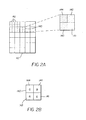
- the filter array 42 is decomposed into a set of tiles 140 that are repeated to form the filter array 42. Each tile includes a set of individual transmittance filters 141, 142, 143 and 144, each with a unique transmittance property.
- the transmittance of the individual filters are reduced by powers of 1 ⁇ 2, hence for a tile 140 with four filters 141, 142, 143 and 144 the transmittances should be 100%, 50%, 25% and 12.5%, respectively.
- the individual filters are arranged within a tile is not critical, but the arrangement should be identical in each tile of the filter array.
- the transmittance of the individual filters is relative to the spectrum of the color emitted by the phosphor plate. Consequently, the filters may have other properties.
- the filters in the array can also share the properties of a standard color filter array.
- One common arrangement is the Bayer pattern (as disclosed in U.S. Patent No. 3,971,065, which is incorporated herein by reference); as shown in Figure 2B, such a filter array will have two (144, 141) of the filters in a tile 140 transmitting green, one (143) transmitting red and the other ( 142 ) transmitting blue.
- a color filter array is introduced prior to the photo-cathode on the microchannel plate in the intensifier, where the color filter array is matched to the spatial channel pattern of the microchannel plate in order to provide the intensifier with the capability of producing color images.
- the color filter array which comprises a pattern of four distinct color filters, e.g., red, blue, green and infrared filters, is arranged into a hexagonal lattice designed to match the channel pattern of the microchannel plate.
- the sensitivity of an image intensifier is partly derived from the fact that the photocathode is mostly responsive to near-infrared radiation (400 - 900 nanometers), part of which is invisible to the human eye. Accordingly, the modulated illumination is restricted to the infra-red region, and the visible region separated by the color filter array is therefore substantially unaffected by the modulation.
- the present invention may be practiced by incorporating the aforementioned spatially varying transmittance pattern into the infrared elements in the color filter array.
- the aforementioned Bayer array shown in Figure 2B may be employed as the color filter array, where the spatially varying transmittance pattern is incorporated into the color elements.
- a primary optical path is established for directing image light toward a single image responsive element.
- a beamsplitter located in the primary optical path separates the image light into two channels, a first channel including an infrared component and a second channel including a color texture component.
- One of the channels continues to traverse the primary optical path and the other channel traverses a secondary optical path distinct from the primary path.
- a modulating element is operative in the first channel to receive the infrared component and a modulating signal, and to generate a processed infrared component with phase data indicative of range information.
- An optical network is provided in the secondary optical path for recombining the secondary optical path into the primary optical path such that the processed infrared component and the color texture component are directed toward the single image responsive element.
- the present invention may be practiced by incorporating the aforementioned spatially varying transmittance filter array into the first channel.
- the color filter array providing the color texture component in the second channel may incorporate the spatially varying transmittance pattern shown in Figure 2B. The advantage of the latter construction therefore is that increased dynamic range may be realized in both the range component and the color texture component.
- the spatially varying exposure pattern of the imaging system measures output radiance I from the microchannel plate 24 using different exposures 150, 152, 154 and 156.
- four exposures are used (corresponding to the four transmittance filters 141, 142, 143 and 144) such that the maximum output exposure 150 (corresponding to the maximum transmittance filter 141) measures low phosphor plate radiance without dropping into the noise, and therefore with high resolution, while the minimum exposure 156 (corresponding to the minimum transmittance filter 144 ) measures high phosphor plate radiance without saturation, and therefore also with high resolution.
- the quantization levels are the most finely spaced, as indicated graphically by the finely spaced quantization bands 160 . This is preferred for regions of low levels of reflected light. However, since the number of quantization levels is fixed and finite, it is also conceivable that in regions reflecting more illuminated light that the pixel under the filter with the highest transmittance will become saturated.
- the second set of quantization bands 162 is more widely spaced than the first and has a greater dynamic range, but with the penalty of having less ability to resolve light levels. Subsequent quantization bands 164 and 166 continue this progression and satisfy this same property. However, as a result, when information from the four exposures are used together the dynamic range of the system is improved by a factor of four.
- each pixel has a bundle of illumination values, referred to here as the pixel bundle.
- the pixel bundle In order to simplify the discussion, consider the objects and overall illumination reflected from the object being identical prior to the filter array. The only difference between the pixel bundles associated with a tile of the filter array are caused by the transmittance levels of the individual filters. The preferred method to estimate range is a least-squares-estimation process. In order to obtain the best results it is preferable that the pixel bundle have as much variation as possible, yet not have levels that are at the minimum or maximum quantization levels.
- pixel values For an eight-bit imager, it is undesirable for pixel values to be either zero or 255. With the described arrangement there are four pixel bundles with illumination samples at different ranges. The preferred method will pick the sample that has the maximum variation, but does not have values with 0 or maximum pixel value. This will select a pixel bundle most free from imager noise and the dynamic range resolution of the imager. For instance, as shown in exemplary form in Figure 4, pixel Q 1 corresponds to the maximum exposure 150 and is clipped at a saturation level 168, while pixel Q 4 corresponds to the minimum exposure 156 and drops into a noise level 170. Accordingly, the values associated with pixels Q 3 and Q 4 contain enough variation to be useful in the least squares estimation process.
- the set of pixel locations of the imager is typically a square lattice 172 .
- the range lattice estimates 174 also form a square lattice, but are effectively offset as shown in Figure 5B to a point midway within a set of four neighboring pixels in an imager lattice 176. This is not a problem in most situations.
- a single range estimate 178 can be formed from elements B 1 ... B 4 for each tile 140, and effectively maintain the same lattice, but with half the period in both spatial directions.
- a logical flowchart is shown for selecting the range estimate at pixel location (i,j).
- Each pixel has an associated pixel bundle as previously described.
- compute measures of data integrity There are a number of methods for performing this task including, but not limited to, measuring the correlation of the fitted data to the pixel bundle data, determining the number of pixels that are clipped, how many pixels have a low signal-to-noise ratio, and so on.
- the preferred method is the product of the correlation and the proportion of samples in the pixel bundle not clipped, or with a low SNR to the total samples in the pixel bundle.
- This measure is referred to as the data integrity measure. If the data integrity measure is deemed adequate (306), e.g., above a threshold, then the range estimate is accepted (308). If not, then an error bound of the range estimate is formed (310) using standard statistical methods. Subsequently, the pixels bundles for neighboring pixels ( e.g., 8 nearest neighbors) are retrieved ( 312 ). For each, the data integrity measure is computed and the results are rank ordered ( 314 ). The best of these is selected (316) and a phase estimate is made (318).
- phase estimate is within the error bounds of the initial pixel bundle (320)
- this pixel bundle is accepted and a range estimate is made (322) and accepted. If not, then if more of the neighboring pixel bundles have not been fully processed ( 324 ), then the next best pixel bundle from the rank ordered list is selected ( 326 ) and the evaluation process performed. If all neighboring pixel bundles have been evaluated and one has not been selected, then the initial range estimate is accepted ( 328 ).
Landscapes
- Engineering & Computer Science (AREA)
- Physics & Mathematics (AREA)
- General Physics & Mathematics (AREA)
- Computer Networks & Wireless Communication (AREA)
- Radar, Positioning & Navigation (AREA)
- Remote Sensing (AREA)
- Electromagnetism (AREA)
- Signal Processing (AREA)
- Multimedia (AREA)
- Image Input (AREA)
- Length Measuring Devices By Optical Means (AREA)
- Image Processing (AREA)
- Image Analysis (AREA)
- Optical Radar Systems And Details Thereof (AREA)
Abstract
Description


Claims (10)
- A scannerless range imaging system having extended dynamic range for capturing range information from illumination reflected from a scene, said scannerless range imaging system comprising:an illumination system for illuminating the scene with modulated illumination of a predetermined modulation frequency, whereby some of the modulated illumination is reflected from objects in the scene;an image intensifier receiving the reflected illumination and including a modulating stage for modulating the reflected modulated illumination from the scene with the predetermined modulation frequency;an image responsive element arranged in an optical path of the image intensifier, said image responsive element including an array of individual pixels for capturing images output by the image intensifier, including at least one image corresponding to the reflected modulated illumination, whereby the modulation of the reflected modulated illumination incorporates a phase delay corresponding to the distance of objects in the scene from the range imaging system; anda transmittance filter including a plurality of filter elements having a spatially varying pattern of transmittance, said filter elements arranged in a one-to-one mapping with respect to the pixels forming the image responsive element, whereby the spatially varying pattern of transmittance provides a plurality of separate exposures which are subsequently combined to form an output image with an expanded dynamic range.
- The range imaging system claimed in claim 1 wherein said plurality of filter elements are arranged in a pattern of tiles, each tile containing a predetermined group of filter elements each providing a different level of transmittance.
- The range imaging system as claimed in claim 1 wherein the transmittance filter is arranged on the image responsive element.
- The range imaging system as claimed in claim 1 further comprising relay optics for imaging the output of the image intensifier filter onto the image responsive element.
- The range imaging system as claimed in claim 1 wherein the transmittance filter includes color filter elements for generating a color texture image.
- The range imaging system as claimed in claim 1 wherein the image intensifier includes a micro-channel plate.
- The range imaging system as claimed in claim 1 wherein the image responsive element is an electronic image sensor.
- The range imaging system as claimed in claim 1 further comprising means for storing the range images as a bundle of associated images.
- The range imaging system as claimed in claim 1 wherein the image responsive element captures a plurality of range images corresponding to the reflected modulated illumination, wherein each range image incorporates the effect of the predetermined modulation frequency together with a phase offset unique for each image.
- A method for obtaining high resolution range estimates in a scannerless range imaging system from a group of pixels having a spatially varying pattern of exposure provided by a transmittance filter overlying the pixels, wherein a bundle of data is obtained for each pixel, said method comprising the steps of:(a) computing data comprising an initial range estimate and an initial phase estimate from a bundle of data for a first pixel in the group;(b) computing a data integrity measure for the bundle of data from the first pixel;(c) accepting the initial range estimate if the data integrity measure is deemed adequate relative to an integrity threshold;(d) if the bundle of data is not acceptable, forming an error boundary relative to the initial range estimate;(e) computing data integrity measures for the bundles of data for neighboring pixels in the group and rank ordering the results;(f) computing a phase estimate for the highest ranked pixel;(g) accepting the phase estimate for the highest ranked pixel if the phase estimate is within the error boundary;(h) otherwise, repeating steps (f) and (g) for the other neighboring pixels until an acceptable phase estimate is determined; and(i) utilizing the phase estimate with other phase estimates similarly generated from other groups of pixels to provide a plurality of separate exposures which are subsequently combined to form an output image with an expanded dynamic range.
Applications Claiming Priority (2)
| Application Number | Priority Date | Filing Date | Title |
|---|---|---|---|
| US103640 | 1987-10-02 | ||
| US10/103,640 US6707054B2 (en) | 2002-03-21 | 2002-03-21 | Scannerless range imaging system having high dynamic range |
Publications (2)
| Publication Number | Publication Date |
|---|---|
| EP1347636A2 true EP1347636A2 (en) | 2003-09-24 |
| EP1347636A3 EP1347636A3 (en) | 2004-11-03 |
Family
ID=27788379
Family Applications (1)
| Application Number | Title | Priority Date | Filing Date |
|---|---|---|---|
| EP03075686A Withdrawn EP1347636A3 (en) | 2002-03-21 | 2003-03-10 | A scannerless range imaging system having high dynamic range |
Country Status (4)
| Country | Link |
|---|---|
| US (1) | US6707054B2 (en) |
| EP (1) | EP1347636A3 (en) |
| JP (1) | JP2003294417A (en) |
| IL (1) | IL154173A0 (en) |
Cited By (2)
| Publication number | Priority date | Publication date | Assignee | Title |
|---|---|---|---|---|
| CN100365436C (en) * | 2006-04-26 | 2008-01-30 | 浙江大学 | A Method of Regionalized Lighting Detection |
| CN100593796C (en) * | 2008-04-25 | 2010-03-10 | 清华大学 | 3D Acquisition System for Dynamic Scenes with Changing Illumination |
Families Citing this family (42)
| Publication number | Priority date | Publication date | Assignee | Title |
|---|---|---|---|---|
| US8300042B2 (en) | 2001-06-05 | 2012-10-30 | Microsoft Corporation | Interactive video display system using strobed light |
| US7259747B2 (en) | 2001-06-05 | 2007-08-21 | Reactrix Systems, Inc. | Interactive video display system |
| US8035612B2 (en) | 2002-05-28 | 2011-10-11 | Intellectual Ventures Holding 67 Llc | Self-contained interactive video display system |
| US7710391B2 (en) * | 2002-05-28 | 2010-05-04 | Matthew Bell | Processing an image utilizing a spatially varying pattern |
| US7092013B2 (en) * | 2002-06-12 | 2006-08-15 | Litton Systems, Inc. | InGaAs image intensifier camera |
| EP1512166A4 (en) * | 2002-06-12 | 2009-12-09 | Litton Systems Inc | IMAGE INTENSIFYING VIEWING APPARATUS |
| AU2003301043A1 (en) | 2002-12-13 | 2004-07-09 | Reactrix Systems | Interactive directed light/sound system |
| US7536032B2 (en) | 2003-10-24 | 2009-05-19 | Reactrix Systems, Inc. | Method and system for processing captured image information in an interactive video display system |
| CN1902930B (en) | 2003-10-24 | 2010-12-15 | 瑞克楚斯系统公司 | Method and system for managing interactive video display system |
| US20060227316A1 (en) * | 2005-04-06 | 2006-10-12 | Phillip Gatt | Three-dimensional imaging device |
| US9128519B1 (en) | 2005-04-15 | 2015-09-08 | Intellectual Ventures Holding 67 Llc | Method and system for state-based control of objects |
| US7193720B2 (en) | 2005-05-17 | 2007-03-20 | Lockheed Martin Coherent Technologies, Inc. | Optical vibration imager |
| US8081822B1 (en) | 2005-05-31 | 2011-12-20 | Intellectual Ventures Holding 67 Llc | System and method for sensing a feature of an object in an interactive video display |
| JP4899351B2 (en) * | 2005-06-17 | 2012-03-21 | 株式会社デンソー | Travel condition determination device and in-vehicle navigation device |
| US8098277B1 (en) | 2005-12-02 | 2012-01-17 | Intellectual Ventures Holding 67 Llc | Systems and methods for communication between a reactive video system and a mobile communication device |
| US7468504B2 (en) * | 2006-03-09 | 2008-12-23 | Northrop Grumman Corporation | Spectral filter for optical sensor |
| US7995191B1 (en) * | 2006-06-29 | 2011-08-09 | Sandia Corporation | Scannerless laser range imaging using loss modulation |
| WO2008124820A1 (en) * | 2007-04-10 | 2008-10-16 | Reactrix Systems, Inc. | Display using a three dimensional vision system |
| US7495748B1 (en) | 2007-08-20 | 2009-02-24 | Sandia Corporation | Scannerless loss modulated flash color range imaging |
| US7420656B1 (en) | 2007-08-20 | 2008-09-02 | Sandia Corporation | Scannerless loss modulated flash color range imaging |
| KR101141087B1 (en) | 2007-09-14 | 2012-07-12 | 인텔렉츄얼 벤처스 홀딩 67 엘엘씨 | Processing of gesture-based user interactions |
| US8159682B2 (en) | 2007-11-12 | 2012-04-17 | Intellectual Ventures Holding 67 Llc | Lens system |
| US8259163B2 (en) | 2008-03-07 | 2012-09-04 | Intellectual Ventures Holding 67 Llc | Display with built in 3D sensing |
| US8595218B2 (en) | 2008-06-12 | 2013-11-26 | Intellectual Ventures Holding 67 Llc | Interactive display management systems and methods |
| KR101556593B1 (en) * | 2008-07-15 | 2015-10-02 | 삼성전자주식회사 | Image processing method |
| US20110018993A1 (en) * | 2009-07-24 | 2011-01-27 | Sen Wang | Ranging apparatus using split complementary color filters |
| JP5670829B2 (en) * | 2011-05-13 | 2015-02-18 | 株式会社 ソキア・トプコン | Light wave distance meter |
| US9071763B1 (en) * | 2012-09-26 | 2015-06-30 | Google Inc. | Uniform illumination image capture |
| WO2014159116A1 (en) | 2013-03-14 | 2014-10-02 | Spiration, Inc. | Valve loader method, system, and apparatus |
| EP3029494A1 (en) * | 2014-12-02 | 2016-06-08 | Sick Ag | Optoelectronic sensor |
| US9800795B2 (en) * | 2015-12-21 | 2017-10-24 | Intel Corporation | Auto range control for active illumination depth camera |
| CN108780142B (en) | 2016-02-29 | 2023-10-31 | 恩耐股份有限公司 | 3D imaging systems and methods |
| US11032498B2 (en) * | 2017-03-17 | 2021-06-08 | The Regents Of The University Of Colorado, A Body | High speed two-dimensional imaging with an analog interface |
| US20190098264A1 (en) * | 2017-03-21 | 2019-03-28 | Irvine Sensors Corporation | Image Intensified Color Camera |
| US10928489B2 (en) * | 2017-04-06 | 2021-02-23 | Microsoft Technology Licensing, Llc | Time of flight camera |
| US10215856B1 (en) | 2017-11-27 | 2019-02-26 | Microsoft Technology Licensing, Llc | Time of flight camera |
| US11428786B2 (en) | 2017-12-03 | 2022-08-30 | Munro Design & Technologies, Llc | Dual waveforms for three-dimensional imaging systems and methods thereof |
| US11212512B2 (en) | 2017-12-28 | 2021-12-28 | Nlight, Inc. | System and method of imaging using multiple illumination pulses |
| US10901087B2 (en) | 2018-01-15 | 2021-01-26 | Microsoft Technology Licensing, Llc | Time of flight camera |
| CN113841034A (en) * | 2019-04-23 | 2021-12-24 | 合刃人工智能有限责任公司 | High Dynamic Range Optical Sensor Integrated with Light Intensity Detector Using Broadband Filters |
| FR3112397B1 (en) * | 2020-07-10 | 2022-08-12 | Commissariat Energie Atomique | Coherent lidar system with improved signal-to-noise ratio |
| JP7596810B2 (en) * | 2021-01-22 | 2024-12-10 | Toppanホールディングス株式会社 | Distance image capturing device and distance image capturing method |
Family Cites Families (13)
| Publication number | Priority date | Publication date | Assignee | Title |
|---|---|---|---|---|
| US3971065A (en) * | 1975-03-05 | 1976-07-20 | Eastman Kodak Company | Color imaging array |
| US4690555A (en) * | 1985-11-01 | 1987-09-01 | Hughes Aircraft Company | Solid-state wavefront slope determination |
| US4935616A (en) * | 1989-08-14 | 1990-06-19 | The United States Of America As Represented By The Department Of Energy | Range imaging laser radar |
| JP3305083B2 (en) * | 1993-12-22 | 2002-07-22 | キヤノン株式会社 | Optical radar |
| US6088086A (en) * | 1995-09-11 | 2000-07-11 | Sandia Corporation | Range determination for scannerless imaging |
| US5990506A (en) * | 1996-03-20 | 1999-11-23 | California Institute Of Technology | Active pixel sensors with substantially planarized color filtering elements |
| GB2341029B (en) * | 1998-08-29 | 2002-12-31 | Marconi Gec Ltd | Cameras |
| US6864916B1 (en) * | 1999-06-04 | 2005-03-08 | The Trustees Of Columbia University In The City Of New York | Apparatus and method for high dynamic range imaging using spatially varying exposures |
| US6118946A (en) * | 1999-06-29 | 2000-09-12 | Eastman Kodak Company | Method and apparatus for scannerless range image capture using photographic film |
| US7084905B1 (en) | 2000-02-23 | 2006-08-01 | The Trustees Of Columbia University In The City Of New York | Method and apparatus for obtaining high dynamic range images |
| US6349174B1 (en) * | 2000-05-17 | 2002-02-19 | Eastman Kodak Company | Method and apparatus for a color scannerless range imaging system |
| US6456793B1 (en) * | 2000-08-03 | 2002-09-24 | Eastman Kodak Company | Method and apparatus for a color scannerless range imaging system |
| US6584283B2 (en) * | 2001-02-02 | 2003-06-24 | Eastman Kodak Company | LED illumination device for a scannerless range imaging system |
-
2002
- 2002-03-21 US US10/103,640 patent/US6707054B2/en not_active Expired - Lifetime
-
2003
- 2003-01-29 IL IL15417303A patent/IL154173A0/en unknown
- 2003-03-10 EP EP03075686A patent/EP1347636A3/en not_active Withdrawn
- 2003-03-18 JP JP2003074156A patent/JP2003294417A/en active Pending
Cited By (2)
| Publication number | Priority date | Publication date | Assignee | Title |
|---|---|---|---|---|
| CN100365436C (en) * | 2006-04-26 | 2008-01-30 | 浙江大学 | A Method of Regionalized Lighting Detection |
| CN100593796C (en) * | 2008-04-25 | 2010-03-10 | 清华大学 | 3D Acquisition System for Dynamic Scenes with Changing Illumination |
Also Published As
| Publication number | Publication date |
|---|---|
| EP1347636A3 (en) | 2004-11-03 |
| IL154173A0 (en) | 2003-07-31 |
| US20030178549A1 (en) | 2003-09-25 |
| JP2003294417A (en) | 2003-10-15 |
| US6707054B2 (en) | 2004-03-16 |
Similar Documents
| Publication | Publication Date | Title |
|---|---|---|
| US6707054B2 (en) | Scannerless range imaging system having high dynamic range | |
| EP1178333A2 (en) | Method and apparatus for a color scannerless range imaging system | |
| US20030147002A1 (en) | Method and apparatus for a color sequential scannerless range imaging system | |
| US11172186B2 (en) | Time-Of-Flight camera system | |
| US7834985B2 (en) | Surface profile measurement | |
| EP1107021A2 (en) | Method and apparatus for a color scannerless range imaging system | |
| JP6452608B2 (en) | Three-dimensional hyperspectral imaging system and method using light detection and ranging (LIDAR) focal plane arrays | |
| US6349174B1 (en) | Method and apparatus for a color scannerless range imaging system | |
| WO2001084182A1 (en) | Device and method for spatially resolved photodetection and demodulation of modulated electromagnetic waves | |
| US20020172514A1 (en) | LED illumination device for a scannerless range imaging system | |
| US20110063437A1 (en) | Distance estimating device, distance estimating method, program, integrated circuit, and camera | |
| EP3519856A2 (en) | System for determining a distance to an object | |
| US11754717B2 (en) | Distance measurement device having external light illuminance measurement function and external light illuminance measurement method | |
| KR101145132B1 (en) | The three-dimensional imaging pulsed laser radar system using geiger-mode avalanche photo-diode focal plane array and auto-focusing method for the same | |
| EP3301478A1 (en) | System for determining a distance to an object | |
| US6507706B1 (en) | Color scannerless range imaging system using an electromechanical grating | |
| CN110574368B (en) | Solid-state cameras, camera systems, and object recognition systems | |
| US6410930B1 (en) | Method and apparatus for aligning a color scannerless range imaging system | |
| US10587347B1 (en) | Heterodyne starring array active imager | |
| JP5441204B2 (en) | Time correlation detection type image sensor and image analysis apparatus | |
| CN117215079A (en) | Digital remote optical device, method of operating the same, and camera system | |
| Ray et al. | Approaches to a color scannerless range imaging system | |
| JP2001280927A (en) | Method and instrument for measuring three-dimensional shape | |
| JPS6132649A (en) | Image reader |
Legal Events
| Date | Code | Title | Description |
|---|---|---|---|
| PUAI | Public reference made under article 153(3) epc to a published international application that has entered the european phase |
Free format text: ORIGINAL CODE: 0009012 |
|
| AK | Designated contracting states |
Kind code of ref document: A2 Designated state(s): AT BE BG CH CY CZ DE DK EE ES FI FR GB GR HU IE IT LI LU MC NL PT RO SE SI SK TR |
|
| AX | Request for extension of the european patent |
Extension state: AL LT LV MK |
|
| PUAL | Search report despatched |
Free format text: ORIGINAL CODE: 0009013 |
|
| AK | Designated contracting states |
Kind code of ref document: A3 Designated state(s): AT BE BG CH CY CZ DE DK EE ES FI FR GB GR HU IE IT LI LU MC NL PT RO SE SI SK TR |
|
| AX | Request for extension of the european patent |
Extension state: AL LT LV MK |
|
| RIC1 | Information provided on ipc code assigned before grant |
Ipc: 7H 04N 5/225 B Ipc: 7G 01S 7/481 B Ipc: 7G 01S 17/89 A |
|
| AKX | Designation fees paid | ||
| REG | Reference to a national code |
Ref country code: DE Ref legal event code: 8566 |
|
| STAA | Information on the status of an ep patent application or granted ep patent |
Free format text: STATUS: THE APPLICATION IS DEEMED TO BE WITHDRAWN |
|
| 18D | Application deemed to be withdrawn |
Effective date: 20050504 |