EP1347559A2 - Wound stator of a rotary electric machine and its winding method - Google Patents
Wound stator of a rotary electric machine and its winding method Download PDFInfo
- Publication number
- EP1347559A2 EP1347559A2 EP03006099A EP03006099A EP1347559A2 EP 1347559 A2 EP1347559 A2 EP 1347559A2 EP 03006099 A EP03006099 A EP 03006099A EP 03006099 A EP03006099 A EP 03006099A EP 1347559 A2 EP1347559 A2 EP 1347559A2
- Authority
- EP
- European Patent Office
- Prior art keywords
- conductors
- connecting portion
- stator core
- conductor
- portions
- Prior art date
- Legal status (The legal status is an assumption and is not a legal conclusion. Google has not performed a legal analysis and makes no representation as to the accuracy of the status listed.)
- Granted
Links
- 238000004804 winding Methods 0.000 title claims abstract description 20
- 238000000034 method Methods 0.000 title claims abstract description 17
- 239000004020 conductor Substances 0.000 claims abstract description 97
- 238000003825 pressing Methods 0.000 claims abstract description 13
- 238000007493 shaping process Methods 0.000 claims abstract description 10
- 238000004519 manufacturing process Methods 0.000 claims abstract description 7
- 230000007423 decrease Effects 0.000 claims description 5
- 238000005452 bending Methods 0.000 claims description 3
- 238000013459 approach Methods 0.000 claims 1
- 239000011295 pitch Substances 0.000 description 8
- 238000003466 welding Methods 0.000 description 4
- 230000001154 acute effect Effects 0.000 description 2
- 239000012212 insulator Substances 0.000 description 2
- 238000002955 isolation Methods 0.000 description 2
- 238000003475 lamination Methods 0.000 description 2
- WABPQHHGFIMREM-UHFFFAOYSA-N lead(0) Chemical compound [Pb] WABPQHHGFIMREM-UHFFFAOYSA-N 0.000 description 2
- 239000004962 Polyamide-imide Substances 0.000 description 1
- 238000007664 blowing Methods 0.000 description 1
- 238000005219 brazing Methods 0.000 description 1
- 210000000078 claw Anatomy 0.000 description 1
- 238000010292 electrical insulation Methods 0.000 description 1
- 239000011810 insulating material Substances 0.000 description 1
- 229920002312 polyamide-imide Polymers 0.000 description 1
- 238000010248 power generation Methods 0.000 description 1
Images



Classifications
-
- H—ELECTRICITY
- H02—GENERATION; CONVERSION OR DISTRIBUTION OF ELECTRIC POWER
- H02K—DYNAMO-ELECTRIC MACHINES
- H02K15/00—Processes or apparatus specially adapted for manufacturing, assembling, maintaining or repairing of dynamo-electric machines
- H02K15/06—Embedding prefabricated windings in the machines
- H02K15/062—Windings in slots; Salient pole windings
- H02K15/064—Windings consisting of separate segments
-
- H—ELECTRICITY
- H02—GENERATION; CONVERSION OR DISTRIBUTION OF ELECTRIC POWER
- H02K—DYNAMO-ELECTRIC MACHINES
- H02K15/00—Processes or apparatus specially adapted for manufacturing, assembling, maintaining or repairing of dynamo-electric machines
- H02K15/04—Processes or apparatus specially adapted for manufacturing, assembling, maintaining or repairing of dynamo-electric machines of windings prior to their mounting into the machines
- H02K15/0414—Processes or apparatus specially adapted for manufacturing, assembling, maintaining or repairing of dynamo-electric machines of windings prior to their mounting into the machines the windings consisting of separate elements, e.g. bars, segments or half coils
-
- H—ELECTRICITY
- H02—GENERATION; CONVERSION OR DISTRIBUTION OF ELECTRIC POWER
- H02K—DYNAMO-ELECTRIC MACHINES
- H02K15/00—Processes or apparatus specially adapted for manufacturing, assembling, maintaining or repairing of dynamo-electric machines
- H02K15/30—Manufacture of winding connections
-
- H—ELECTRICITY
- H02—GENERATION; CONVERSION OR DISTRIBUTION OF ELECTRIC POWER
- H02K—DYNAMO-ELECTRIC MACHINES
- H02K15/00—Processes or apparatus specially adapted for manufacturing, assembling, maintaining or repairing of dynamo-electric machines
- H02K15/30—Manufacture of winding connections
- H02K15/33—Connecting winding sections; Forming leads; Connecting leads to terminals
- H02K15/35—Form-wound windings
-
- H—ELECTRICITY
- H02—GENERATION; CONVERSION OR DISTRIBUTION OF ELECTRIC POWER
- H02K—DYNAMO-ELECTRIC MACHINES
- H02K3/00—Details of windings
- H02K3/04—Windings characterised by the conductor shape, form or construction, e.g. with bar conductors
- H02K3/12—Windings characterised by the conductor shape, form or construction, e.g. with bar conductors arranged in slots
Definitions
- the present invention relates to winding for an electric rotating machine and its manufacturing method.
- an electric rotating machine having U-shaped electric conductors regularly arranged in slots of a stator to increase a lamination factor of the conductors. By increasing the lamination factor, higher output is obtained from the electric rotating machine. In such an electric rotating machine, insulating layers around ends of the conductors need to be removed prior to a connecting process of the conductors.
- Insulating layers 202 are removed from electric conductors 200 around ends, and bare wires 204 are exposed.
- the bare wires 204 are welded together.
- welding reliability decreases when a distance between the bare wires 204 increases, resulting in a poor connection between the two.
- the present invention therefore has an objective to provide a winding for an electric rotating machine in which connections between conductors are improved while isolation between them is maintained.
- the winding of the present invention includes a plurality of conductors that pass through slots of a stator core of an electric rotating machine. Each conductor has housed portions housed in the slots and protruded end portions protruded form the slots. The conductors are lined up in each slot in a radial direction of the stator core.
- Each protruded end portion has an angled portion for connecting one conductor to another protruded from a different slot.
- the angled portion is formed so that it extends in a circumferential direction of the stator core at an angle with respect to a radial section of the stator core.
- the protruded end portion also has an altered portion connecting from the angled portion at one end away from the housed portion.
- the altered portions are shaped so that a distance between two conductors decreases toward their ends, and connected together. Therefore, the connection between the two can be easily made and improved while a certain distance appropriate for electrical isolation between the conductors is maintained.
- the present invention has another objective to provide a method for manufacturing the above-described winding.
- the method of the present invention includes steps of passing conductors in slots of a stator core, shaping protruded portions of the conductors, forming a connecting portion, connecting the connecting portion, and altering the connecting portion.
- the conductors are passing through the slots so that they are lined up in each slot in a radial direction of the stator core.
- protruded portions of the conductors are shaped so that they extend in a circumferential direction of the stator core at an angle with respect to a radial section of the stator core.
- a connecting portion is formed at an end of each conductor.
- closely positioned two conductors are connected in the connecting portion. The connecting portion is altered so that a distance between the conductors decreases toward ends.
- a vehicular alternator 1 includes a stator 2, a rotor 3, a housing 4, and a rectifier 5.
- the rotor 3, which functions as a field magnet and rotates with a shaft 6, includes a Lundell-type pole core 7, a field coil 8, slip rings 9, 10, a mixed flow fan 11.
- the rectifier 5 is located away from a pulley 20.
- the shaft 6 is connected to the pulley 20 and driven by an engine (not shown) installed in a vehicle.
- the mixed flow fan 11 and a centrifugal fan 12 are air blowing devices.
- the Lundell-type pole core 7 is constructed of a pair of pole cores. Each pole core includes a boss 71, a disc 72, and twelve claw poles 73. The boss 71 is assembled to the shaft 6. The disc 72 radially extends from the boss 71.
- the mixed flow fan 11 on a pulley side has two kinds of blades: one arranged at an acute angle and the other arranged at a right angle with respect to a base plate 111 fixed to an end face of the pole core 7.
- the centrifugal fan 12 on the other side has blades arranged at a right angle with respect to a base plate 121 fixed to an end face of the pole core 7.
- the housing 4 is constructed of a front housing 4a and a rear housing 4b.
- Air inlet holes 41 are provided on end faces of the front housing 4a and the rear housing 4b, which is parallel to the end face of the pole core 7.
- Air outlet holes 42 are provided on rounded portions of the front housing 4a and the rear housing 4b.
- the rectifier 5 rectifies an AC voltage output of the stator 2 to a DC voltage.
- the stator 2 is an armature including a stator winding 31 constructed of a plurality of conductor segments 331, 332, a stator core 32 and insulators 34.
- the stator core 32 has a plurality of slots 35.
- the insulators 34 are provided for electrical insulation between the winding 31 and the stator core 32.
- the winding 31 is a three-phase winding passing through the slots 35.
- Ninety-six slots 35 are provided at regular intervals in response to the number of poles of the rotor 3.
- Each slot 35 has an opening on an inner periphery of the stator core 32. When looking at the winding 31 as a set of conductors, each slot holds four conductors as shown in FIG. 2.
- the four conductors are lined up in the radial direction of the stator core 32 forming an inner periphery layer, an inner middle layer, an outer middle layer, and an outer periphery layer.
- the inner periphery layer is located adjacent to the inner periphery of the stator core 32 and the inner middle layer is located next to the inner periphery layer.
- the outer periphery layer is located adjacent to the outer periphery of the stator core 32 and the outer middle layer is located next to the outer periphery layer.
- Each conductor is coated with a layer of insulating material such as polyamide-imide.
- the winding 31 is constructed by connecting the conductors in predetermined patterns.
- the first coil ends 31a are connected via connecting members and the second coil ends 31b are connected each other.
- Each conductor is paired up with another conductor passing through another slot 35 located at a certain pole pitches away. More specifically, a conductor in a certain layer is paired up with another conductor in a different layer in the slot certain pole pitches away.
- a conductor 331a in the inner periphery layer is paired up with another conductor 331b in the outer periphery layer of a slot one pole pitch away in the clockwise direction.
- a conductor 332a in the inner middle layer is paired up with another conductor 332b in the outer middle layer of a slot one pole pitch away in the clockwise direction.
- the paired conductors 331a and 331b, 332a and 332b are connected via connecting members that form turn portions 331c, 332c at the first end located away from the pulley 20.
- the turn portion 331c that connects the conductors 331a and 331b together runs over the turn portion 332c that connects the conductors 332a and 332b.
- the conductors 332a, 332b in the inner and the outer middle layers and their connecting members 332c are covered by the conductors 331a, 331b in the inner and the outer periphery layers and their connecting members 331c.
- an inner layer coil end is formed by the conductors 332a, 332b in the inner and the outer middle layers.
- an outer layer coil end is formed by the conductors 331a, 331b in the inner and the outer middle periphery layers.
- the conductor 332a in the inner middle layer is also paired up with a conductor 331a' in the inner periphery layer of another slot 35 located one pole pitch away in the clockwise direction.
- the conductor 331b' in the outer periphery layer is paired up with a conductor 332b in the outer middle layer of another slot 35 located one pole pitch away in the clockwise direction. Ends of the paired conductors 332a and 331a', 331b' and 332b are connected, respectively, at the second end located adjacent to the pulley 20.
- connecting portions 331d, 331d', 331e, 331e' of the conductors 331a, 331b are bent so that they extend away from each other in the circumferential direction of the stator core 32.
- Connecting portions 332d, 332e of the conductors 332a, 332b are bent so that they extend close to each other in the circumferential direction of the stator core 32.
- end portion 331g, 332g of the connecting portions 331d, 331d', 331e, 331e', 332d, 332e are maintained perpendicular to a radial section of the stator core 32.
- the end portion 331g, 332g of the connecting portions 331d are bent by more than a distance corresponding to a thickness of the insulating layer 37. By doing so, the ends of the paired conductors come close to each other when they are set for connection.
- the ends provided for connection have no insulating layers 37 and conductive members are exposed.
- Adjacent layer coil ends are formed by connecting the conductor 331b in the outer periphery layer to the one 332b in the outer middle layer and the one 331a in the inner periphery layer to the one 332a in the inner middle layer.
- the connected conductors 331b and 332b, 331a and 332a at the second end are lined up without overlapping in the slots 35.
- the conductors 331a, 331b, 332a, 332b are in the form of a U-shaped conductor segment having a substantially rectangular cross-section.
- the conductors 331a, 331b in the inner periphery layer and the outer periphery layer are provided by a large segment 331, which is one continuous conductor formed in a U-shape.
- the conductors 332a, 332b in the inner middle layer and the outer middle layer are provided by a small segment 332, which is one continuous conductor formed in a U-shape.
- the large segment 331 and the small segment 332 form a base conductor segment 33.
- the base segments 33 are regularly positioned in the slots 35 to form a coil made from two turns wound on the stator core 32.
- a lead wire of the stator winding 31 and connecting members that connect the first and the second turns are also conductor segments, they are in different shapes from the base segment 33.
- Six differently shaped conductor segments are used for the lead wire and the connecting members.
- the connection between the first and the second turns are made by connecting the periphery layers and the middle layers. A differently shaped coil end is formed.
- a press die is provided for altering shapes of the end portions 331g and 332g of the conductor segments 331 and 332.
- the press die includes a first die portion 100 and a second die portion 102.
- One surface of the first die portion 100 and the second die portion 102 are sloped, respectively.
- the first and the second die portions 100, 102 are set so that the end portion 331g is angled toward one side when the first and the second dir portion 100, 102 are pressed against the end portion 331g.
- a bare portion 331h is formed at the end of the end portion 331g.
- An insulating layer is removed from the bare portion 331h and a conductive member is exposed.
- the end portion 331g is bent by more than a distance corresponding to a thickness of the insulating layer 37 as shown in FIG. 7B, or a thickness of the removed insulating layer 37.
- the end portion 332g is altered in the same manner.
- the end portions 331g and 332g are angled toward each other.
- the large segment 331 and the small segment 332 of the base segment 33 are arranged so that the turn portion 323c is covered by the turn portion 331c. Then, the base segment 33 is passed through the slot 35 from the one end of the stator core 32.
- One conductor 331a of the large segment 331 is passed through the slot 35 on the most inner periphery side to form the inner periphery layer.
- One conductor 332a of the small segment 332 is passed through the slot 35 at a position next to the conductor 331a.
- the other conductor 331b of the large segment 331 is passed through the slot 35 that is one pole pitch away in the clockwise direction on the most outer periphery side.
- the other conductor 332b of the small segment 332 is passed through the slot 35 at a position next to the conductor 331b.
- the small segment 332 is set inside the large segment 331 as shown in FIG. 4 prior to the above passing step.
- the large segment 331 and the small segment 332 are passing through respective slots 35 from the end portions 331g and 332g with this setting.
- the insulating layer 37 is removed from a part of the end portions 331g and 332g to provide connecting portions 331h and 332h.
- the end portions 331g and 332g are bent toward each other by pressing so that they have good contact for connection.
- straight portions 331a, 332a, 332b', 331b' of the segments 331, 332, which correspond to the conductors, are lined up in the slot 35.
- the other ends of the segments 331, 332 are located in the slot 35 one pole pitch away.
- ends of the connecting portions 331d and 331e are held by jigs (not shown), and then the stator core 32 and the jigs are rotated in the opposite directions. As a result, the ends of the connecting portions 331d and 331e remain perpendicular to a radial section of the stator core 32. The rest of the connecting portions 331d and 331e are bent in the direction that the large segment 331 stretches out so that the ends are positioned about one and a half slots away from their original positions.
- ends of the connecting portions 332d and 332e are held by jigs (not shown), and then the stator core 32 and the jigs are rotated in the opposite directions. As a result, the ends of the connecting portions 332d and 332e remain perpendicular to a radial section of the stator core 32. The rest of the connecting portions 332d and 332e are bent in the direction that the small segment 332 closes in so that the ends are positioned about a half slot away from their original positions.
- the conductors adjacently located in the radial direction of the stator core 32 are bent in the opposite circumferential directions.
- the bending step is performed to all base segments 33 arranged in the slots 35.
- all ends of the connecting portions 331d, 331e, 332d, 332e are perpendicular to the radial section of the stator core 32.
- the rest of the connecting portions 331d, 331e, 332d, 332e extend in the circumferential directions at an acute angle with respect to the radial section.
- the bare potions 331h and 332h are brought into contact.
- the bare portion 331h in the outer periphery layer and the bare portion 332h in the outer middle layer are electrically connected.
- the bare portion 332h in the inner middle layer and the bare portion 331h in the inner periphery layer are electrically connected.
- the electrical connections are made by welding, such as ultrasonic welding, arc welding and brazing, or by other method.
- the bare portions 331h, 332h have a gap between them due to a thickness of the insulating layer 37 when they are placed together for connection as shown in FIG. 9. Especially, the gap increases when a part of the bare wires is removed in a removing process of the insulating layer 37.
- the end portions 331g, 332g are altered in shape to reduce the gap. Therefore, the bare portions 331h, 332 are brought into good contact for connection.
- the segments 331, 332 have a substantially rectangular cross-section. Therefore, contacting areas increases. This improves connection between the segments 331, 332.
- the step for altering the end portions 331g, 332g is performed prior to the passing step in this embodiment. However, it can be performed at any point during the manufacturing of the winding 31.
- the pressing die has an L-shaped first die portion 100a and a prism-shaped second die portion 102a.
- the end portion 331g is positioned between the first die portion 100a and the second die portion 102a.
- the first and the second die portions 100a, 102a are set so that the end portion 331g is angled toward one side when the first and the second dir portion 100a, 102a are pressed against the end portion 331g.
- the end portions 331g and 332g are angled toward each other by more than a distance corresponding to a thickness of the insulating layer 37 as shown in FIG. 8B.
- the end portion 332g is altered in the same manner.
- the end portions 331g and 332g are angled toward each other.
- the winding can be applied to alternators for other than a vehicle.
- the method is not limited to the manufacturing of a stator winding. It can be applied to manufacturing of other kinds of windings.
Landscapes
- Engineering & Computer Science (AREA)
- Power Engineering (AREA)
- Manufacturing & Machinery (AREA)
- Windings For Motors And Generators (AREA)
- Manufacture Of Motors, Generators (AREA)
Abstract
Description
- This application is based on and incorporates herein by reference Japanese Patent Application No. 2002-77474 filed on March 20, 2002.
- The present invention relates to winding for an electric rotating machine and its manufacturing method.
- In recent years, a power generation capacity of a vehicular alternator needs to be improved in response to electrical load increase associate with safety control devices or the like. To meet this requirement, an electric rotating machine having U-shaped electric conductors regularly arranged in slots of a stator to increase a lamination factor of the conductors. By increasing the lamination factor, higher output is obtained from the electric rotating machine. In such an electric rotating machine, insulating layers around ends of the conductors need to be removed prior to a connecting process of the conductors.
- When placing two conductors adjoining to each other for connection, their bare portions cannot be closely placed because the insulating layers have a certain thickness as shown in Fig. 9.
Insulating layers 202 are removed fromelectric conductors 200 around ends, andbare wires 204 are exposed. When connecting theconductors 200, thebare wires 204 are welded together. However, welding reliability decreases when a distance between thebare wires 204 increases, resulting in a poor connection between the two. - The present invention therefore has an objective to provide a winding for an electric rotating machine in which connections between conductors are improved while isolation between them is maintained. The winding of the present invention includes a plurality of conductors that pass through slots of a stator core of an electric rotating machine. Each conductor has housed portions housed in the slots and protruded end portions protruded form the slots. The conductors are lined up in each slot in a radial direction of the stator core.
- Each protruded end portion has an angled portion for connecting one conductor to another protruded from a different slot. The angled portion is formed so that it extends in a circumferential direction of the stator core at an angle with respect to a radial section of the stator core. The protruded end portion also has an altered portion connecting from the angled portion at one end away from the housed portion.
- The altered portions are shaped so that a distance between two conductors decreases toward their ends, and connected together. Therefore, the connection between the two can be easily made and improved while a certain distance appropriate for electrical isolation between the conductors is maintained.
- The present invention has another objective to provide a method for manufacturing the above-described winding. The method of the present invention includes steps of passing conductors in slots of a stator core, shaping protruded portions of the conductors, forming a connecting portion, connecting the connecting portion, and altering the connecting portion. In the passing step, the conductors are passing through the slots so that they are lined up in each slot in a radial direction of the stator core.
- In the shaping step, protruded portions of the conductors are shaped so that they extend in a circumferential direction of the stator core at an angle with respect to a radial section of the stator core. In the forming step, a connecting portion is formed at an end of each conductor. In the altering step, closely positioned two conductors are connected in the connecting portion. The connecting portion is altered so that a distance between the conductors decreases toward ends.
- The above and other objectives, features and advantages of the present invention will become more apparent from the following detailed description made with reference to the accompanying drawings. In the drawings, the same numerals are used for the same components and devices.
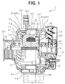
- FIG. 1 is a cross-sectional view of a vehicular alternator according to the first embodiment of the present invention;
- FIG. 2 is a cross-sectional view of a part of a stator core according to the first embodiment;
- FIG. 3 is a perspective view of conductor segments passing through slots of the stator core;
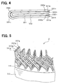
- FIG. 4 is a plane view of small and large conductor segments prepared for passing into the slots;
- FIG. 5 is a perspective view of a part of a stator showing connection between the conductor segments;
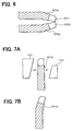
- FIG. 6 is a plane view of ends of the conductors segments after an altering step is performed;
- FIG. 7A is a schematic view of one end of a conductor segment and pressing members showing the altering step according to the second embodiment;
- FIG. 7B is a plane view of the end of the conductor segment after the altering step shown in FIG. 7A is performed;
- FIG. 8A is a schematic view of one end of a conductor and another pressing members showing an modified alter step according to the third embodiment;
- FIG. 8B is a plane view of the end of conductor segment after the altering step shown in FIG. 8A is performed; and
- FIG. 9 is a plane view of ends of conductor segments prepared for connection according to a related art.
-
- The preferred embodiments of the present invention will be explained with reference to the accompanying drawings.
- Referring to FIG. 1, a
vehicular alternator 1 includes astator 2, arotor 3, ahousing 4, and arectifier 5. Therotor 3, which functions as a field magnet and rotates with ashaft 6, includes a Lundell-type pole core 7, afield coil 8,slip rings rectifier 5 is located away from apulley 20. Theshaft 6 is connected to thepulley 20 and driven by an engine (not shown) installed in a vehicle. The mixed flow fan 11 and acentrifugal fan 12 are air blowing devices. - The Lundell-
type pole core 7 is constructed of a pair of pole cores. Each pole core includes aboss 71, adisc 72, and twelveclaw poles 73. Theboss 71 is assembled to theshaft 6. Thedisc 72 radially extends from theboss 71. The mixed flow fan 11 on a pulley side has two kinds of blades: one arranged at an acute angle and the other arranged at a right angle with respect to abase plate 111 fixed to an end face of thepole core 7. Thecentrifugal fan 12 on the other side has blades arranged at a right angle with respect to abase plate 121 fixed to an end face of thepole core 7. - The
housing 4 is constructed of a front housing 4a and a rear housing 4b.Air inlet holes 41 are provided on end faces of the front housing 4a and the rear housing 4b, which is parallel to the end face of thepole core 7.Air outlet holes 42 are provided on rounded portions of the front housing 4a and the rear housing 4b. Therectifier 5 rectifies an AC voltage output of thestator 2 to a DC voltage. - The
stator 2 is an armature including a stator winding 31 constructed of a plurality ofconductor segments stator core 32 andinsulators 34. Thestator core 32 has a plurality ofslots 35. Theinsulators 34 are provided for electrical insulation between the winding 31 and thestator core 32. - The winding 31 is a three-phase winding passing through the
slots 35. Ninety-sixslots 35 are provided at regular intervals in response to the number of poles of therotor 3. Eachslot 35 has an opening on an inner periphery of thestator core 32. When looking at the winding 31 as a set of conductors, each slot holds four conductors as shown in FIG. 2. - The four conductors are lined up in the radial direction of the
stator core 32 forming an inner periphery layer, an inner middle layer, an outer middle layer, and an outer periphery layer. The inner periphery layer is located adjacent to the inner periphery of thestator core 32 and the inner middle layer is located next to the inner periphery layer. The outer periphery layer is located adjacent to the outer periphery of thestator core 32 and the outer middle layer is located next to the outer periphery layer. - Each conductor is coated with a layer of insulating material such as polyamide-imide. The winding 31 is constructed by connecting the conductors in predetermined patterns. The first coil ends 31a are connected via connecting members and the second coil ends 31b are connected each other. Each conductor is paired up with another conductor passing through another
slot 35 located at a certain pole pitches away. More specifically, a conductor in a certain layer is paired up with another conductor in a different layer in the slot certain pole pitches away. - Referring to FIG. 3, a
conductor 331a in the inner periphery layer is paired up with anotherconductor 331b in the outer periphery layer of a slot one pole pitch away in the clockwise direction. In the same manner, aconductor 332a in the inner middle layer is paired up with anotherconductor 332b in the outer middle layer of a slot one pole pitch away in the clockwise direction. The pairedconductors turn portions pulley 20. - The
turn portion 331c that connects theconductors turn portion 332c that connects theconductors conductors members 332c are covered by theconductors members 331c. As a result, an inner layer coil end is formed by theconductors conductors - The
conductor 332a in the inner middle layer is also paired up with aconductor 331a' in the inner periphery layer of anotherslot 35 located one pole pitch away in the clockwise direction. Theconductor 331b' in the outer periphery layer is paired up with aconductor 332b in the outer middle layer of anotherslot 35 located one pole pitch away in the clockwise direction. Ends of the pairedconductors pulley 20. - At the second end, connecting portions 331d, 331d', 331e, 331e' of the
conductors stator core 32. Connectingportions conductors stator core 32. However,end portion stator core 32. - The
end portion layer 37. By doing so, the ends of the paired conductors come close to each other when they are set for connection. The ends provided for connection have no insulatinglayers 37 and conductive members are exposed. Adjacent layer coil ends are formed by connecting theconductor 331b in the outer periphery layer to the one 332b in the outer middle layer and the one 331a in the inner periphery layer to the one 332a in the inner middle layer. Theconnected conductors slots 35. - Furthermore, the
conductors conductors large segment 331, which is one continuous conductor formed in a U-shape. Theconductors small segment 332, which is one continuous conductor formed in a U-shape. - The
large segment 331 and thesmall segment 332 form abase conductor segment 33. Thebase segments 33 are regularly positioned in theslots 35 to form a coil made from two turns wound on thestator core 32. Although a lead wire of the stator winding 31 and connecting members that connect the first and the second turns are also conductor segments, they are in different shapes from thebase segment 33. Six differently shaped conductor segments are used for the lead wire and the connecting members. The connection between the first and the second turns are made by connecting the periphery layers and the middle layers. A differently shaped coil end is formed. - Referring to FIG. 7A, a press die is provided for altering shapes of the
end portions conductor segments first die portion 100 and asecond die portion 102. One surface of thefirst die portion 100 and thesecond die portion 102 are sloped, respectively. The first and thesecond die portions end portion 331g is angled toward one side when the first and thesecond dir portion end portion 331g. - A
bare portion 331h is formed at the end of theend portion 331g. An insulating layer is removed from thebare portion 331h and a conductive member is exposed. Theend portion 331g is bent by more than a distance corresponding to a thickness of the insulatinglayer 37 as shown in FIG. 7B, or a thickness of the removed insulatinglayer 37. Theend portion 332g is altered in the same manner. Theend portions - The
large segment 331 and thesmall segment 332 of thebase segment 33 are arranged so that the turn portion 323c is covered by theturn portion 331c. Then, thebase segment 33 is passed through theslot 35 from the one end of thestator core 32. Oneconductor 331a of thelarge segment 331 is passed through theslot 35 on the most inner periphery side to form the inner periphery layer. Oneconductor 332a of thesmall segment 332 is passed through theslot 35 at a position next to theconductor 331a. Theother conductor 331b of thelarge segment 331 is passed through theslot 35 that is one pole pitch away in the clockwise direction on the most outer periphery side. Theother conductor 332b of thesmall segment 332 is passed through theslot 35 at a position next to theconductor 331b. - The
small segment 332 is set inside thelarge segment 331 as shown in FIG. 4 prior to the above passing step. Thelarge segment 331 and thesmall segment 332 are passing throughrespective slots 35 from theend portions layer 37 is removed from a part of theend portions portions end portions - After the passing step is completed,
straight portions segments slot 35. The other ends of thesegments slot 35 one pole pitch away. - At the second coil ends 31b, ends of the connecting
portions 331d and 331e are held by jigs (not shown), and then thestator core 32 and the jigs are rotated in the opposite directions. As a result, the ends of the connectingportions 331d and 331e remain perpendicular to a radial section of thestator core 32. The rest of the connectingportions 331d and 331e are bent in the direction that thelarge segment 331 stretches out so that the ends are positioned about one and a half slots away from their original positions. - Furthermore, ends of the connecting
portions stator core 32 and the jigs are rotated in the opposite directions. As a result, the ends of the connectingportions stator core 32. The rest of the connectingportions small segment 332 closes in so that the ends are positioned about a half slot away from their original positions. - When the bending step is completed, the conductors adjacently located in the radial direction of the
stator core 32 are bent in the opposite circumferential directions. The bending step is performed to allbase segments 33 arranged in theslots 35. As a result, all ends of the connectingportions stator core 32. The rest of the connectingportions - Because the
end portions bare potions bare portion 331h in the outer periphery layer and thebare portion 332h in the outer middle layer are electrically connected. Thebare portion 332h in the inner middle layer and thebare portion 331h in the inner periphery layer are electrically connected. The electrical connections are made by welding, such as ultrasonic welding, arc welding and brazing, or by other method. - If the
end portions segments bare portions layer 37 when they are placed together for connection as shown in FIG. 9. Especially, the gap increases when a part of the bare wires is removed in a removing process of the insulatinglayer 37. In this embodiment, theend portions bare portions - Furthermore, the
segments segments - The step for altering the
end portions - Referring to FIG. 8A, the pressing die has an L-shaped first die
portion 100a and a prism-shapedsecond die portion 102a. Theend portion 331g is positioned between thefirst die portion 100a and thesecond die portion 102a. The first and thesecond die portions end portion 331g is angled toward one side when the first and thesecond dir portion end portion 331g. - The
end portions layer 37 as shown in FIG. 8B. Theend portion 332g is altered in the same manner. Theend portions - The present invention should not be limited to the embodiment previously discussed and shown in the figures, but may be implemented in various ways without departing from the spirit of the invention. For example, the winding can be applied to alternators for other than a vehicle. The method is not limited to the manufacturing of a stator winding. It can be applied to manufacturing of other kinds of windings.
Claims (11)
- A winding (31) for an electric rotating machine (1) comprising a plurality of conductors (331, 332) passing though slots (35) of a stator core (32) of the electric rotating machine (1), wherein:a plurality of conductors (331, 332) are lined up in each slot (35) in a radial direction of the stator core (32);each conductor (331, 332) has housed portions housed in the slots (35) and protruded end portions protruded from the stator core (32);each protruded end portion has a connecting portion (331d, 331d', 331e, 331e', 332d, 332d') that extends in a circumferential direction of the stator core (32) at an angle with respect to a radial section of the stator core (32) for connecting with another conductor (331, 332) protruded from a different slot (35), and an altered portion at an end of the connecting portion (331d, 331d', 331e, 331e', 332d, 332d'); andthe altered portion is shaped so that a distance between the connector (331, 332) and the other connector (331, 332) decreases toward ends thereof and connected with the altered portion of the other connector (331, 332).
- The winding (31) for an electric rotating machine (1) according to claim 1, wherein:each conductor is coated with an insulating layer (37) except for a bare portion (331h, 332h) located at the end of the connecting portion (331d, 331d', 331e, 331e', 332d, 332d');the bare portion (331h, 332h) is connected with the bare portion (331h, 332h) of the other connector;the altered portion is shaped so that an end thereof adjacent to the other conductor (331, 332) is positioned closer to the altered portion of the other (331, 332) by more than a distance corresponding to a thickness of the insulating layer (37).
- A method for manufacturing a winding (31) of an electric rotating machine (1), comprising:passing conductors (331, 332), coated with insulating layers (37), through each of a plurality of slots (35) provided in a stator core (32) of the electric rotating machine so that the conductors (331, 332) are lined up in each slot (35) in a radial direction of the stator core (32) and ends of the conductors (331, 332) are protruded from the slots (35);shaping protruded portions of the conductors (331, 332) to form a connection portion (331d, 331d', 331e, 331e', 332d, 332d') that extend in a circumferential direction of the stator core (32) at an angle with respect to a radial section of the stator core (32) and adjacent conductors (331, 332) extend in opposite directions;connecting the connecting portion (331d, 331d', 331e, 331e', 332d, 332d') of conductors in pairs that are closely positioned in the connecting portion shaping step;altering an end of the connecting portion (331d, 331d', 331e, 331e', 332d, 332d') so that a distance between ends of the connecting portions (331d, 331d', 331e, 331e', 332d, 332d') of the pair decreases toward ends thereof.
- The method according to claim 3, wherein the altering step includes:shaping the end of the connecting portion (331d, 331d', 331e, 331e', 332d, 332d') so that an end thereof approaches toward a position that the connecting portion (331d, 331d', 331e, 331e', 332d, 332d') of the other conductor (331, 332) is placed; andpassing a plurality of conductors (331, 332) having the connecting portions (331d, 331d', 331e, 331e', 332d, 332d') shaped in the shaping step through each slot (35).
- The method according to claim 3, wherein:the insulating layers (37) are removed from ends of the conductors (331, 332); andthe altered step is performed by bending the connecting portion (331d, 331d', 331e, 331e', 332d, 332d') by pressing.
- The method according to claim 5, wherein the altering step is performed by shaping the connecting portion (331d, 331d', 331e, 331e', 332d, 332d') so that the end thereof is positioned closer to the connecting portion (331d, 331d', 331e, 331e', 332d, 332d') of the other conductor (331, 332) by more than a distance corresponding to a thickness of the insulating layers (37).
- The method according to claim 5, wherein the altering step is performed by shaping the connecting portion (331d, 331d', 331e, 331e', 332d, 332d') so that the end thereof is positioned closer to the connecting portion (331d, 331d', 331e, 331e', 332d, 332d') of the other conductor (331, 332) by more than a distance corresponding to a thickness of the removed insulating layers (37).
- The method according to any one of claims 3 through 7, wherein the connectors (331, 332) have substantially rectangular cross-sections.
- The method according to any one of claims 3 through 8, wherein the altering step includes:placing the connecting portion (331d, 331d', 331e, 331e', 332d, 332d') between a first pressing member (100, 100a) and a second pressing member (102, 102a); andapplying a force to the first and the second pressing members (100, 100a, 102, 102a) toward each other to bend the connecting portion (331d, 331d', 331e, 331e', 332d, 332d').
- The method according to claim 9, wherein the first pressing member (100) and the second pressing member (102) have a slope on one side, respectively.
- The method according to claim 9, wherein:the first pressing member (100a) is formed in an L-shape; andthe second pressing member (102a) is formed in a prism-shape.
Applications Claiming Priority (2)
| Application Number | Priority Date | Filing Date | Title |
|---|---|---|---|
| JP2002077474 | 2002-03-20 | ||
| JP2002077474A JP3775317B2 (en) | 2002-03-20 | 2002-03-20 | Manufacturing method of winding of rotating electric machine |
Publications (3)
| Publication Number | Publication Date |
|---|---|
| EP1347559A2 true EP1347559A2 (en) | 2003-09-24 |
| EP1347559A3 EP1347559A3 (en) | 2004-11-24 |
| EP1347559B1 EP1347559B1 (en) | 2012-08-15 |
Family
ID=27785283
Family Applications (1)
| Application Number | Title | Priority Date | Filing Date |
|---|---|---|---|
| EP03006099A Expired - Lifetime EP1347559B1 (en) | 2002-03-20 | 2003-03-19 | Manufacturing method for a wound stator of a rotary electric machine |
Country Status (3)
| Country | Link |
|---|---|
| US (1) | US6903478B2 (en) |
| EP (1) | EP1347559B1 (en) |
| JP (1) | JP3775317B2 (en) |
Cited By (5)
| Publication number | Priority date | Publication date | Assignee | Title |
|---|---|---|---|---|
| EP1727260A3 (en) * | 2005-05-24 | 2007-11-14 | Hitachi, Ltd. | Joint structure of electric wire, stator of rotary electric machine, method for manufacturing the same |
| CN103151864A (en) * | 2011-08-02 | 2013-06-12 | 瑞美技术有限责任公司 | Electric machine module conductor system |
| CN104584391A (en) * | 2012-07-06 | 2015-04-29 | 三菱电机株式会社 | Rotary electric machine and manufacturing method therefor |
| CN104904098A (en) * | 2013-01-09 | 2015-09-09 | 三菱电机株式会社 | Rotating electrical machine and method for manufacturing armature used for rotating electrical machine |
| CN111416487A (en) * | 2020-05-13 | 2020-07-14 | 常州市臻程智能设备有限公司 | All-in-one is cut to folding of shaded pole motor stator short circuit ring and inserts |
Families Citing this family (22)
| Publication number | Priority date | Publication date | Assignee | Title |
|---|---|---|---|---|
| JP4662141B2 (en) * | 2005-07-28 | 2011-03-30 | 株式会社デンソー | Rotating electric machine including stator |
| US7911106B2 (en) * | 2007-03-29 | 2011-03-22 | Hitachi, Ltd. | Rotary electric machine |
| US7888836B2 (en) * | 2007-04-11 | 2011-02-15 | Asmo Co., Ltd. | DC motor with improved wiring connections |
| BRPI0814770A2 (en) * | 2007-08-03 | 2015-03-03 | Alstom Technology Ltd | ELECTRICAL MACHINE, PARTICULARLY ASYNCHRONOUS THREE-PHASE HYDROGENERATOR |
| JP5402671B2 (en) * | 2010-01-22 | 2014-01-29 | 株式会社デンソー | Rotating electric machine stator |
| JP5482423B2 (en) * | 2010-05-11 | 2014-05-07 | 株式会社デンソー | Electric motor |
| US20140030078A1 (en) | 2011-04-05 | 2014-01-30 | Toyota Jidosha Kabushiki Kaisha | Stator and method of manufacturing stator |
| DE102013225667A1 (en) * | 2012-12-20 | 2014-06-26 | Robert Bosch Gmbh | Method for connecting lead wires of phase winding of stator winding for e.g. generator for vehicles, involves directly integrally connecting wires and cross-section together prior to connection of wires to terminal of connection device |
| KR101998419B1 (en) * | 2012-12-26 | 2019-07-09 | 현대모비스 주식회사 | Hairpin and hairpin winding motor having the same |
| JP6233384B2 (en) | 2015-10-29 | 2017-11-22 | トヨタ自動車株式会社 | Coil end joining method for stator segment coil |
| CN108886307B (en) * | 2016-03-17 | 2020-08-18 | 本田技研工业株式会社 | Jig, stator manufacturing apparatus, and stator manufacturing method |
| JP7107663B2 (en) * | 2017-11-13 | 2022-07-27 | トヨタ自動車株式会社 | Rotating electric machine stator |
| JP6634431B2 (en) * | 2017-12-26 | 2020-01-22 | 本田技研工業株式会社 | Rotating electric machine stator |
| JP6974206B2 (en) * | 2018-02-13 | 2021-12-01 | トヨタ自動車株式会社 | Stator manufacturing method and bending equipment |
| JP2020048359A (en) * | 2018-09-20 | 2020-03-26 | トヨタ自動車株式会社 | Method of manufacturing stator |
| JP7156061B2 (en) * | 2019-01-31 | 2022-10-19 | 株式会社アイシン | Armature and armature manufacturing method |
| JP2020141449A (en) * | 2019-02-27 | 2020-09-03 | 日本電産株式会社 | Stator, motor equipped with it, vehicle equipped with the motor, and coil manufacturing method |
| DE112020004995T5 (en) * | 2019-11-20 | 2022-06-30 | Hitachi Astemo, Ltd. | METHOD OF MANUFACTURING ROTARY ELECTRICAL MACHINE STATOR, ROTARY ELECTRICAL MACHINE STATOR, AND ROTARY ELECTRICAL MACHINE |
| DE102020205684A1 (en) * | 2020-05-06 | 2021-11-11 | Robert Bosch Gesellschaft mit beschränkter Haftung | Stator of an electrical machine |
| DE102021119414A1 (en) * | 2021-07-27 | 2023-02-02 | Additive | Drives GmbH | Process for manufacturing a stator |
| WO2024069694A1 (en) * | 2022-09-26 | 2024-04-04 | 日産自動車株式会社 | Stator of dynamo-electric machine and manufacturing method therefor |
| DE102023200907A1 (en) | 2023-02-03 | 2024-08-08 | Robert Bosch Gesellschaft mit beschränkter Haftung | Method for producing a plug-in winding of an electrical machine and a positioning device |
Citations (3)
| Publication number | Priority date | Publication date | Assignee | Title |
|---|---|---|---|---|
| EP1187299A2 (en) | 2000-09-12 | 2002-03-13 | Mitsubishi Denki Kabushiki Kaisha | Stator of dynamo-electric machine and manufacturing method therefor |
| JP2002077474A (en) | 2000-08-29 | 2002-03-15 | Fuji Photo Film Co Ltd | Printing system |
| EP1330012A2 (en) | 2002-01-18 | 2003-07-23 | Denso Corporation | Stator of a rotary electric machine and manufacturing method thereof |
Family Cites Families (8)
| Publication number | Priority date | Publication date | Assignee | Title |
|---|---|---|---|---|
| JPS5438501A (en) * | 1977-09-02 | 1979-03-23 | Hitachi Ltd | Armature winding end forming device |
| JPS60261337A (en) * | 1984-06-06 | 1985-12-24 | Matsushita Electric Works Ltd | Coreless armature and manufacture thereof |
| US6181043B1 (en) * | 1997-12-10 | 2001-01-30 | Denso Corporation | Alternator for vehicle |
| JP3769990B2 (en) * | 1999-08-06 | 2006-04-26 | 株式会社デンソー | Conductor segment bonding type rotating electrical machine and method for manufacturing the same |
| JP3250533B2 (en) * | 1998-11-25 | 2002-01-28 | 株式会社デンソー | Stator for vehicle alternator and method of manufacturing the same |
| JP3921859B2 (en) * | 1999-01-18 | 2007-05-30 | 株式会社デンソー | Insulating structure of joint, insulating structure of rotating electrical machine, and manufacturing method thereof |
| DE10016151A1 (en) * | 1999-04-02 | 2000-10-05 | Denso Corp | Stator of rotating electrical machine production method, involves providing several U shaped base conductor segments and several shaped connection conductor segments |
| JP4462392B2 (en) * | 2000-02-23 | 2010-05-12 | 三菱電機株式会社 | Method of manufacturing an alternator stator |
-
2002
- 2002-03-20 JP JP2002077474A patent/JP3775317B2/en not_active Expired - Lifetime
-
2003
- 2003-03-14 US US10/387,475 patent/US6903478B2/en not_active Expired - Lifetime
- 2003-03-19 EP EP03006099A patent/EP1347559B1/en not_active Expired - Lifetime
Patent Citations (3)
| Publication number | Priority date | Publication date | Assignee | Title |
|---|---|---|---|---|
| JP2002077474A (en) | 2000-08-29 | 2002-03-15 | Fuji Photo Film Co Ltd | Printing system |
| EP1187299A2 (en) | 2000-09-12 | 2002-03-13 | Mitsubishi Denki Kabushiki Kaisha | Stator of dynamo-electric machine and manufacturing method therefor |
| EP1330012A2 (en) | 2002-01-18 | 2003-07-23 | Denso Corporation | Stator of a rotary electric machine and manufacturing method thereof |
Cited By (10)
| Publication number | Priority date | Publication date | Assignee | Title |
|---|---|---|---|---|
| EP1727260A3 (en) * | 2005-05-24 | 2007-11-14 | Hitachi, Ltd. | Joint structure of electric wire, stator of rotary electric machine, method for manufacturing the same |
| US7615906B2 (en) | 2005-05-24 | 2009-11-10 | Hitachi, Ltd. | Joint structure of electric wire, stator of rotary electric machine, method for manufacturing the same |
| US7948140B2 (en) | 2005-05-24 | 2011-05-24 | Hitachi, Ltd. | Joint structure of electric wire, stator of rotary electric machine, method for manufacturing the same |
| CN103151864A (en) * | 2011-08-02 | 2013-06-12 | 瑞美技术有限责任公司 | Electric machine module conductor system |
| CN104584391A (en) * | 2012-07-06 | 2015-04-29 | 三菱电机株式会社 | Rotary electric machine and manufacturing method therefor |
| CN104584391B (en) * | 2012-07-06 | 2017-05-10 | 三菱电机株式会社 | Rotary electric machine and manufacturing method therefor |
| CN104904098A (en) * | 2013-01-09 | 2015-09-09 | 三菱电机株式会社 | Rotating electrical machine and method for manufacturing armature used for rotating electrical machine |
| CN104904098B (en) * | 2013-01-09 | 2017-08-11 | 三菱电机株式会社 | The manufacture method of armature used in electric rotating machine and electric rotating machine |
| CN111416487A (en) * | 2020-05-13 | 2020-07-14 | 常州市臻程智能设备有限公司 | All-in-one is cut to folding of shaded pole motor stator short circuit ring and inserts |
| CN111416487B (en) * | 2020-05-13 | 2022-10-18 | 常州市臻程智能设备有限公司 | All-in-one is cut to folding of shaded pole motor stator short circuit ring and inserts |
Also Published As
| Publication number | Publication date |
|---|---|
| EP1347559B1 (en) | 2012-08-15 |
| JP3775317B2 (en) | 2006-05-17 |
| US6903478B2 (en) | 2005-06-07 |
| JP2003284300A (en) | 2003-10-03 |
| EP1347559A3 (en) | 2004-11-24 |
| US20030222528A1 (en) | 2003-12-04 |
Similar Documents
| Publication | Publication Date | Title |
|---|---|---|
| EP1347559B1 (en) | Manufacturing method for a wound stator of a rotary electric machine | |
| EP1369979B1 (en) | Method of manufacturing stator winding of rotary electric machine | |
| EP1005137B1 (en) | Stator of AC-generator and method of manufacturing the same | |
| KR100563644B1 (en) | Rotary electric machine | |
| EP1566877B1 (en) | Stator for a rotary electric machine | |
| EP1341292B1 (en) | Method of manufacturing the winding of an electric machine | |
| US20030214190A1 (en) | Connection device for hairpin wound electric machines | |
| US20120161567A1 (en) | Stator for electric rotating machine and method of manufacturing the same | |
| EP1317047B1 (en) | Rotary electric machine and manufacturing method thereof | |
| EP1383230B1 (en) | Method of manufacturing stator winding of an alternator | |
| EP1376823B1 (en) | Stator winding coil ends fastening device for an alternator | |
| JP2004274858A (en) | Method for manufacturing windings of rotating electric machine | |
| JP5594544B2 (en) | Stator for rotating electric machine and method for manufacturing the same | |
| JP2003259613A (en) | Method of manufacturing stator winding of rotating electric machine | |
| CN100449909C (en) | Rotating electric machine and manufacturing method thereof | |
| CN118830173A (en) | Rotating electrical machines, vehicles and slip rings |
Legal Events
| Date | Code | Title | Description |
|---|---|---|---|
| PUAI | Public reference made under article 153(3) epc to a published international application that has entered the european phase |
Free format text: ORIGINAL CODE: 0009012 |
|
| AK | Designated contracting states |
Kind code of ref document: A2 Designated state(s): AT BE BG CH CY CZ DE DK EE ES FI FR GB GR HU IE IT LI LU MC NL PT RO SE SI SK TR |
|
| AX | Request for extension of the european patent |
Extension state: AL LT LV MK |
|
| PUAL | Search report despatched |
Free format text: ORIGINAL CODE: 0009013 |
|
| AK | Designated contracting states |
Kind code of ref document: A3 Designated state(s): AT BE BG CH CY CZ DE DK EE ES FI FR GB GR HU IE IT LI LU MC NL PT RO SE SI SK TR |
|
| AX | Request for extension of the european patent |
Extension state: AL LT LV MK |
|
| RIC1 | Information provided on ipc code assigned before grant |
Ipc: 7H 02K 3/12 B Ipc: 7H 02K 15/00 A |
|
| 17P | Request for examination filed |
Effective date: 20041125 |
|
| AKX | Designation fees paid |
Designated state(s): DE FR IT |
|
| 17Q | First examination report despatched |
Effective date: 20051104 |
|
| 17Q | First examination report despatched |
Effective date: 20051104 |
|
| APBK | Appeal reference recorded |
Free format text: ORIGINAL CODE: EPIDOSNREFNE |
|
| APBN | Date of receipt of notice of appeal recorded |
Free format text: ORIGINAL CODE: EPIDOSNNOA2E |
|
| APBR | Date of receipt of statement of grounds of appeal recorded |
Free format text: ORIGINAL CODE: EPIDOSNNOA3E |
|
| APAF | Appeal reference modified |
Free format text: ORIGINAL CODE: EPIDOSCREFNE |
|
| APBT | Appeal procedure closed |
Free format text: ORIGINAL CODE: EPIDOSNNOA9E |
|
| RTI1 | Title (correction) |
Free format text: MANUFACTURING METHOD FOR A WOUND STATOR OF A ROTARY ELECTRIC MACHINE |
|
| GRAP | Despatch of communication of intention to grant a patent |
Free format text: ORIGINAL CODE: EPIDOSNIGR1 |
|
| GRAS | Grant fee paid |
Free format text: ORIGINAL CODE: EPIDOSNIGR3 |
|
| GRAA | (expected) grant |
Free format text: ORIGINAL CODE: 0009210 |
|
| AK | Designated contracting states |
Kind code of ref document: B1 Designated state(s): DE FR IT |
|
| RIN1 | Information on inventor provided before grant (corrected) |
Inventor name: HAYASHIDA, KOJI Inventor name: KITAKADO, YASUNORI Inventor name: TAKEDA, HIROAKI Inventor name: NAKAMURA, YOSHINORI Inventor name: KATO, MITSURU Inventor name: DOBASHI, MASAOMI Inventor name: MURAHASHI, MOTOHIRO |
|
| REG | Reference to a national code |
Ref country code: DE Ref legal event code: R096 Ref document number: 60341805 Country of ref document: DE Effective date: 20121011 |
|
| PLBE | No opposition filed within time limit |
Free format text: ORIGINAL CODE: 0009261 |
|
| STAA | Information on the status of an ep patent application or granted ep patent |
Free format text: STATUS: NO OPPOSITION FILED WITHIN TIME LIMIT |
|
| 26N | No opposition filed |
Effective date: 20130516 |
|
| REG | Reference to a national code |
Ref country code: DE Ref legal event code: R097 Ref document number: 60341805 Country of ref document: DE Effective date: 20130516 |
|
| REG | Reference to a national code |
Ref country code: FR Ref legal event code: PLFP Year of fee payment: 14 |
|
| REG | Reference to a national code |
Ref country code: FR Ref legal event code: PLFP Year of fee payment: 15 |
|
| REG | Reference to a national code |
Ref country code: FR Ref legal event code: PLFP Year of fee payment: 16 |
|
| PGFP | Annual fee paid to national office [announced via postgrant information from national office to epo] |
Ref country code: DE Payment date: 20220322 Year of fee payment: 20 |
|
| PGFP | Annual fee paid to national office [announced via postgrant information from national office to epo] |
Ref country code: IT Payment date: 20220322 Year of fee payment: 20 Ref country code: FR Payment date: 20220322 Year of fee payment: 20 |
|
| REG | Reference to a national code |
Ref country code: DE Ref legal event code: R071 Ref document number: 60341805 Country of ref document: DE |