EP1347359A2 - Power supply unit - Google Patents
Power supply unit Download PDFInfo
- Publication number
- EP1347359A2 EP1347359A2 EP03003772A EP03003772A EP1347359A2 EP 1347359 A2 EP1347359 A2 EP 1347359A2 EP 03003772 A EP03003772 A EP 03003772A EP 03003772 A EP03003772 A EP 03003772A EP 1347359 A2 EP1347359 A2 EP 1347359A2
- Authority
- EP
- European Patent Office
- Prior art keywords
- power supply
- arithmetic circuit
- accommodating chamber
- supply unit
- supply circuit
- Prior art date
- Legal status (The legal status is an assumption and is not a legal conclusion. Google has not performed a legal analysis and makes no representation as to the accuracy of the status listed.)
- Granted
Links
Images


Classifications
-
- H—ELECTRICITY
- H05—ELECTRIC TECHNIQUES NOT OTHERWISE PROVIDED FOR
- H05K—PRINTED CIRCUITS; CASINGS OR CONSTRUCTIONAL DETAILS OF ELECTRIC APPARATUS; MANUFACTURE OF ASSEMBLAGES OF ELECTRICAL COMPONENTS
- H05K7/00—Constructional details common to different types of electric apparatus
-
- H—ELECTRICITY
- H05—ELECTRIC TECHNIQUES NOT OTHERWISE PROVIDED FOR
- H05K—PRINTED CIRCUITS; CASINGS OR CONSTRUCTIONAL DETAILS OF ELECTRIC APPARATUS; MANUFACTURE OF ASSEMBLAGES OF ELECTRICAL COMPONENTS
- H05K7/00—Constructional details common to different types of electric apparatus
- H05K7/14—Mounting supporting structure in casing or on frame or rack
- H05K7/1422—Printed circuit boards receptacles, e.g. stacked structures, electronic circuit modules or box like frames
- H05K7/1427—Housings
- H05K7/1432—Housings specially adapted for power drive units or power converters
- H05K7/14324—Housings specially adapted for power drive units or power converters comprising modular units, e.g. DIN rail mounted units
-
- H—ELECTRICITY
- H05—ELECTRIC TECHNIQUES NOT OTHERWISE PROVIDED FOR
- H05K—PRINTED CIRCUITS; CASINGS OR CONSTRUCTIONAL DETAILS OF ELECTRIC APPARATUS; MANUFACTURE OF ASSEMBLAGES OF ELECTRICAL COMPONENTS
- H05K7/00—Constructional details common to different types of electric apparatus
- H05K7/14—Mounting supporting structure in casing or on frame or rack
- H05K7/1422—Printed circuit boards receptacles, e.g. stacked structures, electronic circuit modules or box like frames
- H05K7/1427—Housings
- H05K7/1432—Housings specially adapted for power drive units or power converters
Definitions
- the present invention relates to a power supply unit.
- a large number of parts which generate heat such as a coil, a switch transistor, various diodes and the like are mounted to a power supply unit due to its circuit structure.
- the present invention has been accomplished in view of such circumstances, and it is an object of the invention to provide a power supply unit in which parts having low using maximum temperatures are incorporated without increasing the entire power supply unit in size.
- the present invention has the following structures.
- a power supply unit of the present invention comprises a power supply circuit accommodating chamber and an arithmetic circuit accommodating chamber partitioned from each other by a partition wall, and a power supply circuit substrate and an arithmetic circuit substrate are accommodated in the power supply circuit accommodating chamber and the arithmetic circuit accommodating chamber, respectively.
- the accommodating chamber means a chamber capable of accommodating a substrate therein.
- the partition wall functions as a heat insulation wall, it is possible to dispose and accommodate the arithmetic circuit substrate close to the power supply circuit substrate without receiving influence of heat from the power supply circuit.
- At least one of a CPU, an amplifier, a digital IC and an indication LED is contained on the arithmetic circuit substrate.
- the CPU, the amplifier, the digital IC or the indication LED having relatively low using maximum temperature is contained on the arithmetic circuit substrate, it is possible to incorporate such a part without increasing the power supply unit in size.
- the power supply circuit substrate and the arithmetic circuit substrate respectively have connectors, and the connectors are connected to each other through an opening formed in the partition wall.
- a power supply unit having a desired additional function for example, an indicating function or a communication function by connecting an arithmetic circuit of various specifications to one kind of power supply circuit. This is effective for reducing the costs in producing various kinds of power supply units.
- the power supply unit further comprises a casing having the power supply circuit accommodating chamber, and an auxiliary case which is opened toward an outer wall of the casing.
- the outer wall of the casing itself functions as the partition wall for partitioning the power supply circuit accommodating chamber and the arithmetic circuit accommodating chamber from each other, the heat insulating structure can easily be formed only of necessary parts, and heat from the power supply circuit can effectively be insulated.
- the arithmetic circuit substrate calculates an output voltage value and an output current value of the power supply unit.
- calculated output voltage value or output current value can be indicated using the indicating LED contained on the arithmetic circuit substrate.
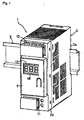
- Fig. 1 is a perspective view of an entire power supply unit 1 according to the present invention.
- Figs. 2 and 3 are exploded perspective views thereof.
- Fig. 4 is a plan view partly in section thereof.
- This power supply unit 1 is formed into a box-like unit which is detachably mounted on a front surface a supporting rail 2 such as a DIN rail.
- the supporting rail 2 is laterally fix to power supply equipment.
- a casing 3 of the power supply unit 1 includes: a case body 3a which is molded by resin into a box shape and which has an opened depth in a front direction; and a front cover 3b which is engaged and communicated with the front face of the case body 3a and which is made of resin such as polycarbonate.
- An interior of the casing 3 is constituted as a power supply circuit accommodating chamber A, and a power supply circuit unit 4 is incorporated and supported in the casing 3.
- a shallow box-like resin auxiliary case 5 whose rear surface is opened is detachably engaged with and connected to the front surface of the casing 3, i.e., a vertically intermediate portion of a front wall of the front cover 3b.
- a space is formed as an arithmetic circuit accommodating chamber B between the front cover 3b and the auxiliary case 4, and an arithmetic circuit unit 6 is incorporated and supported in the space.
- the power supply circuit unit 4 includes, as a substrate for the power supply circuit, a main substrate 7 facing left and right sides, and a front substrate 8 connected to a front portion of the main substrate 7 such as to face front and rear sides.
- Various electronic components 9 constituting the power supply circuit is mounted to the main substrate 7.
- An input terminal blocks 10 and 11 are mounted to the front substrate 8.
- a terminal screw is not illustrated.
- the arithmetic circuit unit 6 includes an arithmetic circuit substrate 12 supported by a front surface of the front cover 3b in parallel. Mounted to the arithmetic circuit substrate 12 are an LED indicator 13 for indicating a voltage set value, an output voltage present value, an output current present value, a peak current value and the like, a mode switch 14 for switching indication modes, a CPU 15 and the like.
- a connector 16a mounted to a back surface of the arithmetic circuit substrate 12 of the arithmetic circuit unit 6 and a connector 16b mounted to the front substrate 8 of the power supply circuit unit 4 are connected to each other through an opening 17 formed in the front cover 3b so that the power supply circuit unit 4 and the arithmetic circuit unit 6 are electrically connected to each other.
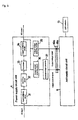
- Fig. 5 is a block diagram of the power supply unit 1 of this embodiment.
- the power supply circuit unit 4 comprises an input rectifying circuit 31 for rectifying and smoothening an AC input, a switching circuit 32 having a switching element such as an FET, a transformer 33 for converting an input into a predetermined output in accordance with on/off operation of the switching element, and an output rectifying circuit 34 for rectifying an output from the transformer 33.
- This structure is basically the same as that of the conventional technique.
- This embodiment includes an output voltage detecting circuit 35, an output current detecting circuit 36 and a current/voltage converter 37 for indicating an output voltage value, an output current value, a peak current value and the like on the LED indicator 13. Outputs of the output voltage detecting circuit 35, the current/voltage converter 37 are sent to the arithmetic circuit unit 6 through the connectors 16a and 16b.
- the arithmetic circuit unit 6 includes an operational amplifier, an A/D converter (both not shown) and the CPU 15.
- a central portion 3b' of the front cover 3b which is a front wall of the casing 3 functions as a heat-insulating partition wall for insulating the power supply circuit accommodating chamber A and the arithmetic circuit accommodating chamber B, and heat from the power supply circuit unit 4 is effectively insulated.
- the front substrate 8 is formed with a circuit pattern having a relatively thickness, for example, a wide area (not shown). Noise emission from a switching element and the like in the power supply circuit unit 4 is absorbed and shield by the circuit pattern so that the noise is prevented from being transmitted to the arithmetic circuit unit 6.
- the power supply circuit unit 4 and the arithmetic circuit unit 6 are close to each other, the arithmetic circuit unit 6 can appropriately be operated without being adversely affected by the noise emission.
- a metal film may be formed or metal may be evaporated on a surface of the front cover 3b on the side of the power supply circuit unit 4 to shield the noise emission.
- the present invention can also be carried out in the following manners:
- the power supply circuit accommodating chamber and the arithmetic circuit accommodating chamber are partitioned by the partition wall. Therefore, it is unnecessary to largely separate the arithmetic circuit substrate and the power supply circuit substrate from each other for heat insulation, it is possible to disposed the arithmetic circuit substrate close to the power supply circuit substrate without being adversely effected by heat from the power supply circuit unit, and the arithmetic circuit unit can be incorporated while reducing the entire unit in size.
Landscapes
- Engineering & Computer Science (AREA)
- Microelectronics & Electronic Packaging (AREA)
- Dc-Dc Converters (AREA)
- Casings For Electric Apparatus (AREA)
- Electric Clocks (AREA)
Abstract
Description
Claims (5)
- A power supply unit comprising a power supply circuit accommodating chamber and an arithmetic circuit accommodating chamber partitioned from each other by a partition wall, wherein a power supply circuit substrate and an arithmetic circuit substrate are accommodated in said power supply circuit accommodating chamber and said arithmetic circuit accommodating chamber, respectively.
- A power supply unit according to claim 1, wherein at least one of a CPU, an amplifier, a digital IC and an indication LED is contained on said arithmetic circuit substrate.
- A power supply unit according to claim 1, wherein said power supply circuit substrate and said arithmetic circuit substrate respectively have connectors, and said connectors are connected to each other through an opening formed in said partition wall.
- A power supply unit according to claim 1, further comprising a casing having said power supply circuit accommodating chamber, and an auxiliary case which is opened toward an outer wall of said casing.
- A power supply unit according to claim 2, wherein said arithmetic circuit substrate calculates an output voltage value and an output current value of said power supply unit.
Applications Claiming Priority (2)
| Application Number | Priority Date | Filing Date | Title |
|---|---|---|---|
| JP2002044631A JP3606263B2 (en) | 2002-02-21 | 2002-02-21 | Power supply |
| JP2002044631 | 2002-02-21 |
Publications (3)
| Publication Number | Publication Date |
|---|---|
| EP1347359A2 true EP1347359A2 (en) | 2003-09-24 |
| EP1347359A3 EP1347359A3 (en) | 2006-10-18 |
| EP1347359B1 EP1347359B1 (en) | 2015-04-08 |
Family
ID=27783933
Family Applications (1)
| Application Number | Title | Priority Date | Filing Date |
|---|---|---|---|
| EP03003772.5A Expired - Lifetime EP1347359B1 (en) | 2002-02-21 | 2003-02-19 | Power supply unit |
Country Status (6)
| Country | Link |
|---|---|
| US (1) | US6809923B2 (en) |
| EP (1) | EP1347359B1 (en) |
| JP (1) | JP3606263B2 (en) |
| KR (1) | KR100511669B1 (en) |
| CN (2) | CN1440113B (en) |
| TW (1) | TWI225331B (en) |
Families Citing this family (9)
| Publication number | Priority date | Publication date | Assignee | Title |
|---|---|---|---|---|
| GB2375233B (en) * | 2001-09-19 | 2003-12-03 | Camden Electronics Ltd | A mounted enclosure |
| JP2006262563A (en) * | 2005-03-15 | 2006-09-28 | Omron Corp | Power supply |
| US8021193B1 (en) * | 2005-04-25 | 2011-09-20 | Nvidia Corporation | Controlled impedance display adapter |
| DE102007026898A1 (en) * | 2007-06-11 | 2008-05-15 | Siemens Ag | Modular device e.g. switch, push-button, has housing with snapping device in rear side for mounting device in support unit, and two opposite side walls, where one of side walls is provided with ventilation openings |
| CN103580451B (en) * | 2012-08-08 | 2016-06-01 | 群光电能科技股份有限公司 | Combined power supply device and power supply system with combined power supply device |
| SG2013069224A (en) * | 2013-09-13 | 2015-04-29 | Rockwell Automation Asia Pacific Business Ctr Pte Ltd | Motor drive with inherent power isolation |
| SG2013094396A (en) * | 2013-12-19 | 2015-07-30 | Rockwell Automation Asia Pacific Business Ctr Pte Ltd | Slice-io housing with side ventilation |
| US9864352B2 (en) | 2015-06-01 | 2018-01-09 | Rockwell Automation Asia Pacific Business Ctr. Pte., Ltd. | Slice I/O—field power bus breaker |
| JP6361842B1 (en) * | 2017-12-27 | 2018-07-25 | 株式会社安川電機 | Inverter device |
Family Cites Families (16)
| Publication number | Priority date | Publication date | Assignee | Title |
|---|---|---|---|---|
| US4508402A (en) * | 1981-02-27 | 1985-04-02 | Sharp Kabushiki Kaisha | Integrated circuit package and display panel |
| US4652769A (en) * | 1984-02-14 | 1987-03-24 | Ion Tech, Inc. | Module power supply |
| DE3440756A1 (en) * | 1984-11-08 | 1986-05-07 | CEAG Licht- und Stromversorgungstechnik GmbH, 6800 Mannheim | POWER SUPPLY |
| DE3638251C1 (en) * | 1986-11-10 | 1988-05-05 | Vero Electronics Gmbh | Back wall for a housing for receiving electrical assemblies |
| KR920005988B1 (en) * | 1988-08-31 | 1992-07-25 | 가부시기가이샤 히다찌세이사꾸쇼 | Inverter |
| FR2652443A1 (en) * | 1989-09-26 | 1991-03-29 | Inst Vzryvozaschischennogo | ANTIDEFLAGRANT ELECTRICAL APPARATUS. |
| US5297025A (en) * | 1992-10-28 | 1994-03-22 | Onan Corporation | Power supply assembly |
| JPH0795771A (en) * | 1993-09-20 | 1995-04-07 | Sansha Electric Mfg Co Ltd | Power supply cooling structure |
| KR100190154B1 (en) * | 1994-06-16 | 1999-06-01 | 가나이 쓰도무 | Inverter apparatus |
| JP3235777B2 (en) * | 1996-09-24 | 2001-12-04 | 株式会社三社電機製作所 | Power supply |
| JPH10224762A (en) * | 1997-02-07 | 1998-08-21 | Miharu Tsushin Kk | Amplifier for catv |
| JPH1141951A (en) | 1997-07-15 | 1999-02-12 | Mitsubishi Electric Corp | General-purpose inverter |
| JP3279535B2 (en) * | 1998-12-09 | 2002-04-30 | 株式会社日立製作所 | Inverter |
| JP4231141B2 (en) * | 1999-03-19 | 2009-02-25 | Idec株式会社 | Switching power supply |
| US6272007B1 (en) * | 1999-06-28 | 2001-08-07 | Sun Microsystems, Inc. | Computer system cooling configuration |
| FR2814848A1 (en) * | 2000-10-03 | 2002-04-05 | Koninkl Philips Electronics Nv | Cable television amplification circuit has arrangement for removing electrical interference from the power supply by shielding the power supply from the processing unit and filtering the power connection |
-
2002
- 2002-02-21 JP JP2002044631A patent/JP3606263B2/en not_active Expired - Lifetime
-
2003
- 2003-01-24 KR KR10-2003-0004726A patent/KR100511669B1/en not_active Expired - Lifetime
- 2003-02-11 US US10/361,846 patent/US6809923B2/en not_active Expired - Lifetime
- 2003-02-17 TW TW092103175A patent/TWI225331B/en not_active IP Right Cessation
- 2003-02-18 CN CN031037380A patent/CN1440113B/en not_active Expired - Lifetime
- 2003-02-18 CN CNU032015380U patent/CN2678236Y/en not_active Expired - Lifetime
- 2003-02-19 EP EP03003772.5A patent/EP1347359B1/en not_active Expired - Lifetime
Also Published As
| Publication number | Publication date |
|---|---|
| EP1347359B1 (en) | 2015-04-08 |
| JP2003244939A (en) | 2003-08-29 |
| TWI225331B (en) | 2004-12-11 |
| TW200304266A (en) | 2003-09-16 |
| CN1440113B (en) | 2010-05-05 |
| EP1347359A3 (en) | 2006-10-18 |
| KR20030069807A (en) | 2003-08-27 |
| US6809923B2 (en) | 2004-10-26 |
| CN1440113A (en) | 2003-09-03 |
| KR100511669B1 (en) | 2005-08-30 |
| JP3606263B2 (en) | 2005-01-05 |
| CN2678236Y (en) | 2005-02-09 |
| US20030174465A1 (en) | 2003-09-18 |
Similar Documents
| Publication | Publication Date | Title |
|---|---|---|
| US6091604A (en) | Power module for a frequency converter | |
| US20110069451A1 (en) | Inverter with Electrical and Electronic Components Arranged in a Sealed Housing | |
| TW200505327A (en) | Electronic device, information processor, and electromagnetic radiation suppressing member | |
| FR2803138B1 (en) | CONTINUOUS CURRENT TO AC CONVERTER | |
| US6809923B2 (en) | Power supply unit | |
| MY116078A (en) | Cooling structure of electronic appliance | |
| US20050136969A1 (en) | Case of mobile terminal | |
| KR20080103905A (en) | Inverter casing | |
| AU2003250103A1 (en) | Electronics housing with integrated thermal dissipater | |
| US10201071B1 (en) | Power supply with thermal insulation function | |
| EP0932330B1 (en) | Electronic apparatus | |
| US6542368B2 (en) | Heat sink and power source unit employing the same | |
| GB2110024A (en) | Portable radio device for protecting a radio circuit from static electricity | |
| US6903936B2 (en) | Power regulator | |
| JP2009081233A (en) | Electronic circuit device and hermetic electric compressor | |
| AU2001258193A1 (en) | Cooling system, especially for electrical appliances | |
| EP1085795A3 (en) | Cabinet with electrical and/or electronic units | |
| US7262970B2 (en) | Electronic device | |
| US4833569A (en) | Plug-in power supply module | |
| US6313974B1 (en) | Resistor for a servo amplifier and servo amplifier provided thereof | |
| CN220629858U (en) | Signal source device | |
| JPH0992992A (en) | Electrical equipment | |
| EP0989777A3 (en) | Heat providing structure for an electrical assembly | |
| RU97114145A (en) | ELECTRICAL CONVERTER | |
| JPS6459895A (en) | Electronic part mounting device |
Legal Events
| Date | Code | Title | Description |
|---|---|---|---|
| PUAI | Public reference made under article 153(3) epc to a published international application that has entered the european phase |
Free format text: ORIGINAL CODE: 0009012 |
|
| AK | Designated contracting states |
Kind code of ref document: A2 Designated state(s): AT BE BG CH CY CZ DE DK EE ES FI FR GB GR HU IE IT LI LU MC NL PT SE SI SK TR |
|
| AX | Request for extension of the european patent |
Extension state: AL LT LV MK RO |
|
| PUAL | Search report despatched |
Free format text: ORIGINAL CODE: 0009013 |
|
| AK | Designated contracting states |
Kind code of ref document: A3 Designated state(s): AT BE BG CH CY CZ DE DK EE ES FI FR GB GR HU IE IT LI LU MC NL PT SE SI SK TR |
|
| AX | Request for extension of the european patent |
Extension state: AL LT LV MK RO |
|
| 17P | Request for examination filed |
Effective date: 20070417 |
|
| AKX | Designation fees paid |
Designated state(s): DE FR GB IT |
|
| 17Q | First examination report despatched |
Effective date: 20070823 |
|
| REG | Reference to a national code |
Ref country code: DE Ref legal event code: R079 Ref document number: 60347478 Country of ref document: DE Free format text: PREVIOUS MAIN CLASS: G06F0001260000 Ipc: H05K0007140000 |
|
| GRAP | Despatch of communication of intention to grant a patent |
Free format text: ORIGINAL CODE: EPIDOSNIGR1 |
|
| RIC1 | Information provided on ipc code assigned before grant |
Ipc: H05K 7/14 20060101AFI20141128BHEP |
|
| INTG | Intention to grant announced |
Effective date: 20141218 |
|
| GRAS | Grant fee paid |
Free format text: ORIGINAL CODE: EPIDOSNIGR3 |
|
| GRAA | (expected) grant |
Free format text: ORIGINAL CODE: 0009210 |
|
| RIN1 | Information on inventor provided before grant (corrected) |
Inventor name: ISOZUMI, MASASHI Inventor name: OBA, TSUNETOSHI Inventor name: HORIE, TAKASHI Inventor name: OGAWA, TADAHIKO |
|
| AK | Designated contracting states |
Kind code of ref document: B1 Designated state(s): DE FR GB IT |
|
| REG | Reference to a national code |
Ref country code: GB Ref legal event code: FG4D |
|
| REG | Reference to a national code |
Ref country code: DE Ref legal event code: R096 Ref document number: 60347478 Country of ref document: DE Effective date: 20150521 |
|
| REG | Reference to a national code |
Ref country code: DE Ref legal event code: R097 Ref document number: 60347478 Country of ref document: DE |
|
| PLBE | No opposition filed within time limit |
Free format text: ORIGINAL CODE: 0009261 |
|
| STAA | Information on the status of an ep patent application or granted ep patent |
Free format text: STATUS: NO OPPOSITION FILED WITHIN TIME LIMIT |
|
| 26N | No opposition filed |
Effective date: 20160111 |
|
| REG | Reference to a national code |
Ref country code: FR Ref legal event code: ST Effective date: 20161028 |
|
| PG25 | Lapsed in a contracting state [announced via postgrant information from national office to epo] |
Ref country code: FR Free format text: LAPSE BECAUSE OF NON-PAYMENT OF DUE FEES Effective date: 20160229 |
|
| PGFP | Annual fee paid to national office [announced via postgrant information from national office to epo] |
Ref country code: GB Payment date: 20211231 Year of fee payment: 20 |
|
| PGFP | Annual fee paid to national office [announced via postgrant information from national office to epo] |
Ref country code: DE Payment date: 20211230 Year of fee payment: 20 |
|
| PGFP | Annual fee paid to national office [announced via postgrant information from national office to epo] |
Ref country code: IT Payment date: 20220111 Year of fee payment: 20 |
|
| REG | Reference to a national code |
Ref country code: DE Ref legal event code: R071 Ref document number: 60347478 Country of ref document: DE |
|
| REG | Reference to a national code |
Ref country code: GB Ref legal event code: PE20 Expiry date: 20230218 |
|
| PG25 | Lapsed in a contracting state [announced via postgrant information from national office to epo] |
Ref country code: GB Free format text: LAPSE BECAUSE OF EXPIRATION OF PROTECTION Effective date: 20230218 |