EP1347316A1 - Hinterleuchtungseinrichtung - Google Patents
Hinterleuchtungseinrichtung Download PDFInfo
- Publication number
- EP1347316A1 EP1347316A1 EP03003018A EP03003018A EP1347316A1 EP 1347316 A1 EP1347316 A1 EP 1347316A1 EP 03003018 A EP03003018 A EP 03003018A EP 03003018 A EP03003018 A EP 03003018A EP 1347316 A1 EP1347316 A1 EP 1347316A1
- Authority
- EP
- European Patent Office
- Prior art keywords
- light
- backlighting device
- cavity
- light source
- plastic
- Prior art date
- Legal status (The legal status is an assumption and is not a legal conclusion. Google has not performed a legal analysis and makes no representation as to the accuracy of the status listed.)
- Withdrawn
Links
Images

Classifications
-
- G—PHYSICS
- G02—OPTICS
- G02B—OPTICAL ELEMENTS, SYSTEMS OR APPARATUS
- G02B6/00—Light guides; Structural details of arrangements comprising light guides and other optical elements, e.g. couplings
- G02B6/0001—Light guides; Structural details of arrangements comprising light guides and other optical elements, e.g. couplings specially adapted for lighting devices or systems
- G02B6/0096—Light guides; Structural details of arrangements comprising light guides and other optical elements, e.g. couplings specially adapted for lighting devices or systems the lights guides being of the hollow type
Definitions
- Known symbol backlighting for example for operating devices, actuators etc., have reflectors made of white plastic, light guide or a free Clearance with direct illumination.
- DE 92 16 107 U1 discloses a light display that is bundled around a light to be transmitted to a symbol which has a light-conducting body which, from viewed from the light exit to the light entry opening, has a bulbous S-shape.
- a light guide mushroom is known from DE 199 43 589 A1, via the light of a light source coupled in the middle of the mushroom and guided to a scale. The light emission is off-center.
- the invention has for its object to show a backlighting device, the more effective use of light by a light source for a symbol to be illuminated as well as at relatively large distances between light source and symbol or realized with relatively small symbols.
- the invention is based on the idea of carrying out the light transport instead of by means of a reflector or a light guide via an arbitrarily colored plastic with an inserted cavity and a preferably polished inner surface, whereby an increased reflection with grazing incidence (large angles of incidence against the normal) is used.
- the light from a light source is transported to the symbol by reflection in this cavity or on the inner surface.
- the light source itself should preferably be flat.
- the angles of incidence of the light are kept as large as possible. Angles> 70 ° are particularly advantageous.
- the cavity is composed of one or more partial surfaces, which are preferably partial surfaces of an ellipsoid.
- the selection of the semiaxes of the partial ellipsoidal surfaces takes place according to the aspects of large light incidence angles (against the surface normal) and coverage of large emission solid angle ranges of the light sources in which the light intensity is large.
- the different partial areas can each have different semiaxes.
- the solution can reduce the operating current of a light source. Also low-cost LEDs can be used. By reducing the operating current the lifespan of the light source is extended and the waste heat development reduced. Another advantage is that the area to be screened can show a higher wall thickness.
- the optical properties of the reflector are more independent of the material coloring. Dark colors can also be used.
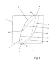
- a plastic 1 with a cavity 2 is shown in a schematic diagram, which is embedded obliquely in the plastic 1.
- a light source 3 an LED.
- the light a of the LED 3 is fed into a light entry opening 2.1 of the cavity 2 and transported to the symbol 6 by reflection on the partial surfaces 4.1, 4.2 and 4.3 and 4.4 of the cavity 2, which is preferably designed as an ellipsoid 5, the light being decoupled via a light exit opening 2.2 he follows.
- the symbol 6 to be illuminated is preferably directly above the light source 3.
- This symbol 5 can be a search or a function or pointer symbol of an actuating element etc., which is by means of a centrally mounted light source 12 should be illuminated.
- FIG. 2 shows a simplified illustration of such an application in a rotary switch or the like which has a symbol 11 in the rotary knob 10 which is to be illuminated with the light source 12.
- the parts of the rotary switch that are used for its actual function are not shown in this illustration for the sake of clarity.
- An artificial peat part 13 used for this application has an upper part 13.1 which is movable relative to a lower part 13.2 and in which a part 14.1, 14.2 of a common cavity 14 is embedded.
- the separation of the two hollow parts 14.1, 14.2 takes place via rotating surfaces 17.1, 17.2.
- the cavity 14 consists of reflector surfaces 15.1, 15.2 and 15.3, 15.4, which preferably form an ellipsoid part 16.1 and an ellipse profile part 16.2, which are separated by the rotating surfaces 17.1, 17.2.
- the light a is fed from the light source 12 into the cavity 14 via a light entry opening 14.3 and is transported to the symbol 11 within the two profile parts 16.1 and 16.2 by reflection on the partial or reflector surfaces 15.1-15.4.
- the symbol 11 is supplied with light a through a light exit opening 14.4.
- the cavity 2 or 14 preferably has a polished inner surface 2.5 or 14.5.
Landscapes
- Physics & Mathematics (AREA)
- General Physics & Mathematics (AREA)
- Optics & Photonics (AREA)
- Planar Illumination Modules (AREA)
- Illuminated Signs And Luminous Advertising (AREA)
- Rotary Switch, Piano Key Switch, And Lever Switch (AREA)
Abstract
Description
Die Einfallswinkel des Lichtes werden möglichst groß gehalten. Von besonderem Vorteil sind Winkel > 70°.
Der Hohlraum setzt sich aus einer oder mehreren Teilflächen, die vorzugsweise Teilflächen eines Ellipsoid sind, zusammen. Die Auswahl der Halbachsen der Ellipsoidteilflächen erfolgt jeweils nach den Gesichtspunkten große Lichteinfallswinkel (gegen die Flächennormale) und Abdeckung großer Emissions-Raumwinkelbereiche der Lichtquellen in denen die Lichtstärke groß ist. Die verschiedenen Teilflächen können jeweils verschiedene Halbachsen haben.
- Fig. 1
- eine Prinzipdarstellung,
- Fig. 2
- eine Anwendung in einem Drehschalter.
Bei einem senkrecht zur Lichtquelle 3 ausgerichteten Hohlraum 2 ist das auszuleuchtende Symbol 6 vorzugsweise direkt oberhalb der Lichtquelle 3.
Ein für diese Anwendung verwendetes Kunststorfteil 13 weist ein gegenüber einem unteren Teil 13.2 bewegbares oberes Teil 13.1 auf, in welche jeweils ein Teil 14.1, 14.2 eines gemeinsamen Hohlraumes 14 eingebettet sind. Die Trennung beider Hohlteile 14.1, 14.2 erfolgt über Rotationsflächen 17.1, 17.2. Der Hohlraum 14 besteht aus Reflektorflächen 15.1, 15.2 sowie 15.3, 15.4, die vorzugsweise ein Ellipsoidteil 16.1 und ein Ellipsenprofilteil 16.2 bilden, die durch die Rotationsflächen 17.1, 17.2 getrennt sind.
Das Licht a wird von der Lichtquelle 12 in den Hohlraum 14 über eine Lichteintrittsöffnung 14.3 eingespeist und innerhalb der beiden Profilteile 16.1 und 16.2 durch Reflexion an den Teil- bzw. Reflektorflächen 15.1-15.4 zum Symbol 11 transportiert.
Durch eine Lichtaustrittsöffnung 14.4 wird das Symbol 11 mit Licht a versorgt.
Der Hohlraum 2 bzw. 14 weist vorzugsweise eine polierte Innenoberfläche 2.5 bzw. 14.5 auf.
Claims (11)
- Hinterleuchtungseinrichtung, insbesondere für ein Symbol eines Betätigungelementes, bestehend aus einem Kunststoff und ausweisend eine Lichtquelle, dadurch gekennzeichnet, daßin den Kunststoff (1, 13) ein Hohlraum (2, 14) eingebettet ist, der von einer Lichteintrittsöffnung (2.1, 14.1) des Lichtes (a) der Lichtquelle (3, 12) zur Lichtaustrittsöffnung (2.2, 14.2) im Kunststoff (1, 14) verläuft.
- Hinterleuchtungseinrichtung nach Anspruch 1, dadurch gekennzeichnet, daß der Hohlraum (2, 14) im Kunststoff (1, 13) schräg eingebettet ist.
- Hinterleuchtungseinrichtung nach Anspruch 1, dadurch gekennzeichnet, daß der Hohlraum (2, 14) im Kunststoff (1, 13) senkrecht zur Lichtquelle (3, 12) verläuft.
- Hinterleuchtungseinrichtung nach einem der Ansprüche 1 bis 3, dadurch gekennzeichnet, daß der Hohiraum (2, 14) eine polierte Innenoberfläche (2.5, 14.5) aufweist.
- Hinterleuchtungseinrichtung nach einem der Ansprüche 1 bis 4, dadurch gekennzeichnet, daß die Einfallswinkel des Lichtes (a) > 70° sind.
- Hinterleuchtungseinrichtung nach einem der Ansprüche 1 bis 5, dadurch gekennzeichnet, daß der Hohlraum (2, 14) sich aus einer oder mehreren Teilflächen (4.1-4.4, 15.1-15.4) zusammensetzt.
- Hinterleuchtungseinrichtung nach Anspruch 6, dadurch gekennzeichnet, daß die Teilflächen (4.1-4.4, 15.1-15.4) die eines Ellipsoids (5, 16.1, 16.2) sind.
- Hinterleuchtungseinrichtung nach einem der Ansprüche, dadurch gekennzeichnet, daß die Auswahl der Halbachsen der Ellipsoidteilflächen (4.1- 4.4, 15.1-15.4) nach den Gesichtspunkten große Lichteinfallswinkel gegen die Flächennormale und Abdeckung großer Emissions-Raumwinkelbereiche der Lichtquellen in denen die Lichtstärke groß ist, erfolgt.
- Hinterleuchtungseinrichtung nach Anspruch 8, dadurch gekennzeichnet, daß die verschiedenen Teilflächen (4.1-4.4, 15.1-15.4) verschiedene Halbachsen haben können.
- Hinterleuchtungseinrichtung nach einem der Ansprüche, dadurch gekennzeichnet, daß bei sich gegeneinander bewegbaren Reflektorteilen (13.1, 13.2) mit Hohlräumen (14.1, 14.2) Rotationsflächen (17.1, 17.2) eingebunden sind, wobei die Lichtquelle (12) und das Symbol (11) sich jeweils in einem Brennpunkt der Ellipse bzw. des Ellipsoids befinden.
- Hinterleuchtungseinrichtung nach einem der Ansprüche, dadurch gekennzeichnet, daß die Rotationsflächen (17.1, 17.2) zwei voneinander getrennte Ellipsen- bzw. Ellipsoid-Profilteile (16.1, 16.2) bilden.
Applications Claiming Priority (2)
| Application Number | Priority Date | Filing Date | Title |
|---|---|---|---|
| DE10211967 | 2002-03-19 | ||
| DE10211967A DE10211967B4 (de) | 2002-03-19 | 2002-03-19 | Hinterleuchtungseinrichtung |
Publications (1)
| Publication Number | Publication Date |
|---|---|
| EP1347316A1 true EP1347316A1 (de) | 2003-09-24 |
Family
ID=27771407
Family Applications (1)
| Application Number | Title | Priority Date | Filing Date |
|---|---|---|---|
| EP03003018A Withdrawn EP1347316A1 (de) | 2002-03-19 | 2003-02-12 | Hinterleuchtungseinrichtung |
Country Status (4)
| Country | Link |
|---|---|
| US (1) | US6966683B2 (de) |
| EP (1) | EP1347316A1 (de) |
| JP (1) | JP2003295796A (de) |
| DE (1) | DE10211967B4 (de) |
Citations (5)
| Publication number | Priority date | Publication date | Assignee | Title |
|---|---|---|---|---|
| EP0426433A2 (de) * | 1989-10-30 | 1991-05-08 | Minnesota Mining And Manufacturing Company | Beleuchtungskörper für äusserlich beleuchtete Anzeige |
| DE9216107U1 (de) | 1992-11-26 | 1993-04-15 | Siemens AG, 8000 München | Leuchtanzeige für ein Kommunikationsendgerät |
| WO1994016265A1 (en) * | 1992-12-31 | 1994-07-21 | Minnesota Mining And Manufacturing Company | Pole light having a programmable footprint |
| DE19943589A1 (de) | 1999-09-11 | 2001-04-05 | Preh Elektro Feinmechanik | Lichtleiterpilz |
| EP1180640A1 (de) * | 2000-08-14 | 2002-02-20 | 3M Italia S.P.A. | Lichtabzweigungsvorrichtung für Lichtleiterlampe |
Family Cites Families (8)
| Publication number | Priority date | Publication date | Assignee | Title |
|---|---|---|---|---|
| DE8708254U1 (de) * | 1987-04-29 | 1987-08-06 | Hans & Jos. Kronenberg Gmbh, 5060 Bergisch Gladbach | Vorrichtung zur Standortanzeige |
| US4843524A (en) * | 1988-05-06 | 1989-06-27 | Krent Edward D | Illuminated decorations for furnishings and other like structures |
| DE4445388A1 (de) * | 1993-12-20 | 1995-08-03 | Peter Dipl Ing Gus | Vorrichtung zur Erzielung mindestens einer Lichtstruktur |
| DE19504996A1 (de) * | 1995-02-15 | 1996-08-22 | Siegesmund Raeder | Verfahren zur Herstellung einer Leuchtanzeige-Vorrichtung und danach hergestellte Leuchtanzeigevorrichtung |
| DE19741585C1 (de) * | 1997-09-20 | 1998-10-01 | Parsytec Computer Gmbh | Leuchtdioden-Array, Verfahren zu seiner Herstellung und Verwendung derselben |
| JP2000149621A (ja) * | 1998-11-16 | 2000-05-30 | Koito Mfg Co Ltd | 車両用前照灯 |
| US6481130B1 (en) * | 2000-08-11 | 2002-11-19 | Leotek Electronics Corporation | Light emitting diode linear array with lens stripe for illuminated signs |
| DE10058252A1 (de) * | 2000-11-23 | 2002-08-08 | Berthold Westhoff | Effektleuchte |
-
2002
- 2002-03-19 DE DE10211967A patent/DE10211967B4/de not_active Expired - Fee Related
-
2003
- 2003-02-12 EP EP03003018A patent/EP1347316A1/de not_active Withdrawn
- 2003-03-05 JP JP2003058293A patent/JP2003295796A/ja not_active Withdrawn
- 2003-03-19 US US10/390,693 patent/US6966683B2/en not_active Expired - Fee Related
Patent Citations (5)
| Publication number | Priority date | Publication date | Assignee | Title |
|---|---|---|---|---|
| EP0426433A2 (de) * | 1989-10-30 | 1991-05-08 | Minnesota Mining And Manufacturing Company | Beleuchtungskörper für äusserlich beleuchtete Anzeige |
| DE9216107U1 (de) | 1992-11-26 | 1993-04-15 | Siemens AG, 8000 München | Leuchtanzeige für ein Kommunikationsendgerät |
| WO1994016265A1 (en) * | 1992-12-31 | 1994-07-21 | Minnesota Mining And Manufacturing Company | Pole light having a programmable footprint |
| DE19943589A1 (de) | 1999-09-11 | 2001-04-05 | Preh Elektro Feinmechanik | Lichtleiterpilz |
| EP1180640A1 (de) * | 2000-08-14 | 2002-02-20 | 3M Italia S.P.A. | Lichtabzweigungsvorrichtung für Lichtleiterlampe |
Also Published As
| Publication number | Publication date |
|---|---|
| JP2003295796A (ja) | 2003-10-15 |
| US20040022048A1 (en) | 2004-02-05 |
| US6966683B2 (en) | 2005-11-22 |
| DE10211967A1 (de) | 2003-10-09 |
| DE10211967B4 (de) | 2006-08-31 |
Similar Documents
| Publication | Publication Date | Title |
|---|---|---|
| DE2634264A1 (de) | Halbleiter-lumineszenzbauelement | |
| DE102008004836A1 (de) | Operationsleuchte mit einstellbaren Lichtquellen, die ein Lichtfeld mit einer gaussschen Verteilung erzeugen kann | |
| DE4300701A1 (en) | Illuminated push button for motor vehicle - has reciprocal, different shapes of controllable resistors and switches, and illuminated part to display their function | |
| DE4227468C2 (de) | Elektrische Schaltereinheit, insbesondere zur Steuerung von Klimaanlagen in Kraftfahrzeugen | |
| EP2622261A1 (de) | Anordnung zur lichtabgabe | |
| EP0998880A2 (de) | Zahnärztliches Präparationsinstrument | |
| DE10210161B4 (de) | Getränkebereiter, insbesondere Kaffeemaschine | |
| DE10129972A1 (de) | Beleuchtungseinrichtung | |
| DE10036323A1 (de) | Leuchte für Fahrzeuge | |
| DE20317444U1 (de) | Beleuchtungsvorrichtung, insbesondere für Straßen, Wege, Plätze o.dgl. | |
| DE20110289U1 (de) | Beleuchtungseinrichtung | |
| EP1347316A1 (de) | Hinterleuchtungseinrichtung | |
| DE10208045A1 (de) | Beleuchtungsring | |
| EP1030102B1 (de) | Optische Anzeigevorrichtung für elektrische Haushaltsgeräte | |
| DE19606179A1 (de) | Leuchtvorrichtung | |
| DE9403794U1 (de) | Wertpapier-Prüfgerät | |
| DE202007008890U1 (de) | Leuchteinrichtung, die an einem Körper anzubringen ist | |
| DE202007006815U1 (de) | Bauelement | |
| DE9419593U1 (de) | Unterwasserlampe | |
| EP1136751A1 (de) | Hinweis- und Sicherheitsleuchte | |
| DE10315771A1 (de) | Leuchte mit geschlossener Lichtabstrahlfläche | |
| EP0931976A1 (de) | Anordnung zum gleichmässigen Be- bzw. Ausleuchten einer Fläche zum Anzeigen von Informationen | |
| WO2008046394A2 (de) | Beleuchtungsvorrichtung | |
| DE10011765B4 (de) | Leuchte mit einer optischen Vorrichtung zur Erzeugung eines kreisbogenförmig ausgebildeten Lichtspektrums | |
| DE20100214U1 (de) | Videoüberwachungsanordnung |
Legal Events
| Date | Code | Title | Description |
|---|---|---|---|
| PUAI | Public reference made under article 153(3) epc to a published international application that has entered the european phase |
Free format text: ORIGINAL CODE: 0009012 |
|
| 17P | Request for examination filed |
Effective date: 20030212 |
|
| AK | Designated contracting states |
Kind code of ref document: A1 Designated state(s): AT BE BG CH CY CZ DE DK EE ES FI FR GB GR HU IE IT LI LU MC NL PT SE SI SK TR |
|
| AX | Request for extension of the european patent |
Extension state: AL LT LV MK RO |
|
| RAP1 | Party data changed (applicant data changed or rights of an application transferred) |
Owner name: PREH GMBH |
|
| AKX | Designation fees paid |
Designated state(s): DE FR |
|
| 17Q | First examination report despatched |
Effective date: 20070301 |
|
| STAA | Information on the status of an ep patent application or granted ep patent |
Free format text: STATUS: THE APPLICATION IS DEEMED TO BE WITHDRAWN |
|
| 18D | Application deemed to be withdrawn |
Effective date: 20100831 |