EP1346102B1 - Steel cord for reinforcing off-the-road tires and conveyor belts - Google Patents
Steel cord for reinforcing off-the-road tires and conveyor belts Download PDFInfo
- Publication number
- EP1346102B1 EP1346102B1 EP01983598A EP01983598A EP1346102B1 EP 1346102 B1 EP1346102 B1 EP 1346102B1 EP 01983598 A EP01983598 A EP 01983598A EP 01983598 A EP01983598 A EP 01983598A EP 1346102 B1 EP1346102 B1 EP 1346102B1
- Authority
- EP
- European Patent Office
- Prior art keywords
- steel
- steel cord
- metal core
- layer
- core strand
- Prior art date
- Legal status (The legal status is an assumption and is not a legal conclusion. Google has not performed a legal analysis and makes no representation as to the accuracy of the status listed.)
- Expired - Lifetime
Links
- 229910000831 Steel Inorganic materials 0.000 title claims abstract description 169
- 239000010959 steel Substances 0.000 title claims abstract description 169
- 230000003014 reinforcing effect Effects 0.000 title 1
- 229910052751 metal Inorganic materials 0.000 claims abstract description 62
- 239000002184 metal Substances 0.000 claims abstract description 62
- 229920000642 polymer Polymers 0.000 claims abstract description 24
- 239000002861 polymer material Substances 0.000 claims description 30
- 229920000139 polyethylene terephthalate Polymers 0.000 claims description 9
- -1 polypropylene Polymers 0.000 claims description 6
- 238000000034 method Methods 0.000 claims description 5
- 239000004952 Polyamide Substances 0.000 claims description 4
- 239000004698 Polyethylene Substances 0.000 claims description 4
- 239000004743 Polypropylene Substances 0.000 claims description 4
- 229920002647 polyamide Polymers 0.000 claims description 4
- 229920000728 polyester Polymers 0.000 claims description 4
- 229920000573 polyethylene Polymers 0.000 claims description 4
- 229920001155 polypropylene Polymers 0.000 claims description 4
- 239000004810 polytetrafluoroethylene Substances 0.000 claims description 4
- 229920001343 polytetrafluoroethylene Polymers 0.000 claims description 4
- 230000002787 reinforcement Effects 0.000 claims description 4
- 229920001169 thermoplastic Polymers 0.000 claims description 3
- 229920001577 copolymer Polymers 0.000 claims description 2
- 239000004800 polyvinyl chloride Substances 0.000 claims description 2
- 239000000463 material Substances 0.000 claims 2
- 239000010410 layer Substances 0.000 description 91
- 238000010276 construction Methods 0.000 description 19
- 229910000851 Alloy steel Inorganic materials 0.000 description 3
- PXHVJJICTQNCMI-UHFFFAOYSA-N Nickel Chemical compound [Ni] PXHVJJICTQNCMI-UHFFFAOYSA-N 0.000 description 2
- 229910052799 carbon Inorganic materials 0.000 description 2
- 239000011248 coating agent Substances 0.000 description 2
- 238000000576 coating method Methods 0.000 description 2
- 239000012792 core layer Substances 0.000 description 2
- 229910052748 manganese Inorganic materials 0.000 description 2
- 239000011572 manganese Substances 0.000 description 2
- ZOXJGFHDIHLPTG-UHFFFAOYSA-N Boron Chemical compound [B] ZOXJGFHDIHLPTG-UHFFFAOYSA-N 0.000 description 1
- OKTJSMMVPCPJKN-UHFFFAOYSA-N Carbon Chemical compound [C] OKTJSMMVPCPJKN-UHFFFAOYSA-N 0.000 description 1
- VYZAMTAEIAYCRO-UHFFFAOYSA-N Chromium Chemical compound [Cr] VYZAMTAEIAYCRO-UHFFFAOYSA-N 0.000 description 1
- RYGMFSIKBFXOCR-UHFFFAOYSA-N Copper Chemical compound [Cu] RYGMFSIKBFXOCR-UHFFFAOYSA-N 0.000 description 1
- PWHULOQIROXLJO-UHFFFAOYSA-N Manganese Chemical compound [Mn] PWHULOQIROXLJO-UHFFFAOYSA-N 0.000 description 1
- ZOKXTWBITQBERF-UHFFFAOYSA-N Molybdenum Chemical compound [Mo] ZOKXTWBITQBERF-UHFFFAOYSA-N 0.000 description 1
- OAICVXFJPJFONN-UHFFFAOYSA-N Phosphorus Chemical compound [P] OAICVXFJPJFONN-UHFFFAOYSA-N 0.000 description 1
- XUIMIQQOPSSXEZ-UHFFFAOYSA-N Silicon Chemical compound [Si] XUIMIQQOPSSXEZ-UHFFFAOYSA-N 0.000 description 1
- NINIDFKCEFEMDL-UHFFFAOYSA-N Sulfur Chemical compound [S] NINIDFKCEFEMDL-UHFFFAOYSA-N 0.000 description 1
- 238000005275 alloying Methods 0.000 description 1
- 229910052796 boron Inorganic materials 0.000 description 1
- 229910052804 chromium Inorganic materials 0.000 description 1
- 239000011651 chromium Substances 0.000 description 1
- 229910017052 cobalt Inorganic materials 0.000 description 1
- 239000010941 cobalt Substances 0.000 description 1
- GUTLYIVDDKVIGB-UHFFFAOYSA-N cobalt atom Chemical compound [Co] GUTLYIVDDKVIGB-UHFFFAOYSA-N 0.000 description 1
- 229910052802 copper Inorganic materials 0.000 description 1
- 239000010949 copper Substances 0.000 description 1
- 229910052750 molybdenum Inorganic materials 0.000 description 1
- 239000011733 molybdenum Substances 0.000 description 1
- 229910052759 nickel Inorganic materials 0.000 description 1
- 230000003287 optical effect Effects 0.000 description 1
- 230000035515 penetration Effects 0.000 description 1
- 229910052698 phosphorus Inorganic materials 0.000 description 1
- 239000011574 phosphorus Substances 0.000 description 1
- 229910052710 silicon Inorganic materials 0.000 description 1
- 239000010703 silicon Substances 0.000 description 1
- 229910052717 sulfur Inorganic materials 0.000 description 1
- 239000011593 sulfur Substances 0.000 description 1
- 230000009466 transformation Effects 0.000 description 1
- 229910052720 vanadium Inorganic materials 0.000 description 1
- LEONUFNNVUYDNQ-UHFFFAOYSA-N vanadium atom Chemical compound [V] LEONUFNNVUYDNQ-UHFFFAOYSA-N 0.000 description 1
Images


Classifications
-
- D—TEXTILES; PAPER
- D07—ROPES; CABLES OTHER THAN ELECTRIC
- D07B—ROPES OR CABLES IN GENERAL
- D07B1/00—Constructional features of ropes or cables
- D07B1/06—Ropes or cables built-up from metal wires, e.g. of section wires around a hemp core
-
- D—TEXTILES; PAPER
- D07—ROPES; CABLES OTHER THAN ELECTRIC
- D07B—ROPES OR CABLES IN GENERAL
- D07B1/00—Constructional features of ropes or cables
- D07B1/16—Ropes or cables with an enveloping sheathing or inlays of rubber or plastics
- D07B1/165—Ropes or cables with an enveloping sheathing or inlays of rubber or plastics characterised by a plastic or rubber inlay
-
- B—PERFORMING OPERATIONS; TRANSPORTING
- B60—VEHICLES IN GENERAL
- B60C—VEHICLE TYRES; TYRE INFLATION; TYRE CHANGING; CONNECTING VALVES TO INFLATABLE ELASTIC BODIES IN GENERAL; DEVICES OR ARRANGEMENTS RELATED TO TYRES
- B60C9/00—Reinforcements or ply arrangement of pneumatic tyres
- B60C9/0007—Reinforcements made of metallic elements, e.g. cords, yarns, filaments or fibres made from metal
-
- D—TEXTILES; PAPER
- D07—ROPES; CABLES OTHER THAN ELECTRIC
- D07B—ROPES OR CABLES IN GENERAL
- D07B1/00—Constructional features of ropes or cables
- D07B1/06—Ropes or cables built-up from metal wires, e.g. of section wires around a hemp core
- D07B1/0606—Reinforcing cords for rubber or plastic articles
- D07B1/0613—Reinforcing cords for rubber or plastic articles the reinforcing cords being characterised by the rope configuration
-
- D—TEXTILES; PAPER
- D07—ROPES; CABLES OTHER THAN ELECTRIC
- D07B—ROPES OR CABLES IN GENERAL
- D07B1/00—Constructional features of ropes or cables
- D07B1/06—Ropes or cables built-up from metal wires, e.g. of section wires around a hemp core
- D07B1/0606—Reinforcing cords for rubber or plastic articles
- D07B1/062—Reinforcing cords for rubber or plastic articles the reinforcing cords being characterised by the strand configuration
- D07B1/0626—Reinforcing cords for rubber or plastic articles the reinforcing cords being characterised by the strand configuration the reinforcing cords consisting of three core wires or filaments and at least one layer of outer wires or filaments, i.e. a 3+N configuration
-
- D—TEXTILES; PAPER
- D07—ROPES; CABLES OTHER THAN ELECTRIC
- D07B—ROPES OR CABLES IN GENERAL
- D07B1/00—Constructional features of ropes or cables
- D07B1/06—Ropes or cables built-up from metal wires, e.g. of section wires around a hemp core
- D07B1/0606—Reinforcing cords for rubber or plastic articles
- D07B1/062—Reinforcing cords for rubber or plastic articles the reinforcing cords being characterised by the strand configuration
- D07B1/0633—Reinforcing cords for rubber or plastic articles the reinforcing cords being characterised by the strand configuration having a multiple-layer configuration
-
- D—TEXTILES; PAPER
- D07—ROPES; CABLES OTHER THAN ELECTRIC
- D07B—ROPES OR CABLES IN GENERAL
- D07B2201/00—Ropes or cables
- D07B2201/20—Rope or cable components
- D07B2201/2015—Strands
- D07B2201/2046—Strands comprising fillers
-
- D—TEXTILES; PAPER
- D07—ROPES; CABLES OTHER THAN ELECTRIC
- D07B—ROPES OR CABLES IN GENERAL
- D07B2201/00—Ropes or cables
- D07B2201/20—Rope or cable components
- D07B2201/2047—Cores
- D07B2201/2052—Cores characterised by their structure
- D07B2201/2059—Cores characterised by their structure comprising wires
- D07B2201/2061—Cores characterised by their structure comprising wires resulting in a twisted structure
-
- D—TEXTILES; PAPER
- D07—ROPES; CABLES OTHER THAN ELECTRIC
- D07B—ROPES OR CABLES IN GENERAL
- D07B2201/00—Ropes or cables
- D07B2201/20—Rope or cable components
- D07B2201/2047—Cores
- D07B2201/2052—Cores characterised by their structure
- D07B2201/2059—Cores characterised by their structure comprising wires
- D07B2201/2062—Cores characterised by their structure comprising wires comprising fillers
-
- D—TEXTILES; PAPER
- D07—ROPES; CABLES OTHER THAN ELECTRIC
- D07B—ROPES OR CABLES IN GENERAL
- D07B2201/00—Ropes or cables
- D07B2201/20—Rope or cable components
- D07B2201/2047—Cores
- D07B2201/2052—Cores characterised by their structure
- D07B2201/2065—Cores characterised by their structure comprising a coating
-
- D—TEXTILES; PAPER
- D07—ROPES; CABLES OTHER THAN ELECTRIC
- D07B—ROPES OR CABLES IN GENERAL
- D07B2201/00—Ropes or cables
- D07B2201/20—Rope or cable components
- D07B2201/2071—Spacers
- D07B2201/2074—Spacers in radial direction
-
- D—TEXTILES; PAPER
- D07—ROPES; CABLES OTHER THAN ELECTRIC
- D07B—ROPES OR CABLES IN GENERAL
- D07B2205/00—Rope or cable materials
- D07B2205/20—Organic high polymers
-
- D—TEXTILES; PAPER
- D07—ROPES; CABLES OTHER THAN ELECTRIC
- D07B—ROPES OR CABLES IN GENERAL
- D07B2205/00—Rope or cable materials
- D07B2205/20—Organic high polymers
- D07B2205/201—Polyolefins
-
- D—TEXTILES; PAPER
- D07—ROPES; CABLES OTHER THAN ELECTRIC
- D07B—ROPES OR CABLES IN GENERAL
- D07B2205/00—Rope or cable materials
- D07B2205/20—Organic high polymers
- D07B2205/2071—Fluor resins
Definitions
- the present invention relates to steel cords, and more in particular to steel cords adapted to be used to reinforce rubber tires, especially off-the-road tires and conveyor belts.
- a steel cord comprising different layers of steel elements are used.
- One or more layers of steel elements surround a steel cord, which is called "metal core strand".
- These steel elements may be steel cords or strands, so providing e.g. a typical off-the-road steel cord construction 7x(3+9).
- the elements may also be steel filaments, so providing concentric layered cords, e.g. 3+9+15 .
- Such a steel cord is described in GB1100686, comprising a core wire or strand being coated with a layer of not vulcanised rubber.
- the object of the invention is to reduce the loss of tensile strength or breaking load of high tensile steel cords, adapted to be used to reinforce rubber tires, especially off-the-road tires, or conveyor belts.
- a steel cord comprises one or more layers of steel elements twisted round a metal core strand.
- These steel elements may be steel filaments, or steel strands.
- One or more layers of steel elements may be twisted around the metal core strand, using the same or a different twisting direction and/or angle.
- Different steel filament diameters or strand constructions may be used to provide the steel cord as subject of the invention.
- the steel cord as subject of the invention may be a so-called compact cord, a multi-strand construction or a concentric layered construction.
- a steel cord according to the present invention is characterized in that a layer of polymer material is provided between the metal core strand and at least one layer of steel elements, which is twisted around this metal core strand, wherein the thickness of the polymer material is more than 0.02mm, and less than or equal to 0.12mm
- Filaments which are used to provide the different steel elements of the steel cord as subject of the invention preferably have a tensile strength larger than 2000N/mm 2 , preferably more than 2500 N/mm 2 and most preferably more than 2800 N/mm 2 .
- Diameters of the filaments which are used to provide the different steel elements of the steel cord as subject of the invention are less than 0.8mm, preferably between 0.15 and 0.6 mm, most preferably between 0.175 and 0.35mm.
- a steel cord according to the present invention is characterized in that a layer of polymer material is provided between the metal core strand and at least one layer of steel elements, which is twisted around this metal core strand.
- This layer of polymer material separates the metal core strand and the adjacent layer of steel elements from each other.
- the polymer layer prevents to a large extent the existence of contacts and contact points between the filaments of the metal core strand and filaments of the adjacent layer of steel elements.
- the thickness of the polymer layer between metal core strand and adjacent layer of steel elements is to be more than 0.02 mm, preferably more than 0.035mm, most preferably more than 0.05 mm., e.g. more than 0.1 mm.
- This thickness is measured through the following procedure:
- Such thickness is obtainable by providing a layer of polymer material around the metal core strand, before the adjacent layer of steel elements is twisted around this core layer.
- the thickness of the polymer layer, provided around the metal core strand before twisting the adjacent layer of steel elements is minimum 0.05 mm, most preferably more than 0.1 mm. The thickness is measured as the optical diameter difference coated/non coated strand or filament, divided by 2. A smaller thickness of the polymer layer before twisting the adjacent layer of steel elements results in frequent local contact points between metal core strand and adjacent steel elements, which is probably caused by the specific diameters of the filaments used.
- the fine filaments used to provide the adjacent layer or the strands, present in the adjacent layers may cut through the polymer layer during twisting of the steel cord as subject of the invention.
- the adjacent steel elements move radial inwards, towards the metal core strand.
- the steel elements are so-to-say pressed in the polymer layer.
- the polymer layer may be locally pushed away, or so-to-say 'cut' by the high local radial stresses upon the polymer layer.
- the adjacent layer of steel elements is twisted around the metal core strand in the opposite direction of the twisting direction of the metal core strand.
- the adjacent layer of steel elements preferably are twisted around the metal core strand in 'Z'-direction, after providing a polymer layer round the core layer.
- the polymer layer may not be too thick either.
- a too thick layer of polymer material between metal core strand and adjacent layer of steel elements would make the steel cord as subject of the invention unstable and not useful for the reinforcement of off- the-road tires and conveyor belts. Even more, a thick coating increases the cord diameter, so a thicker layer of rubber is required to embed the cords, which also increases the cost.
- the thickness of the polymer layer between metal core strand and adjacent layer of steel elements may not exceed 0.120 mm.
- Steel cords as subject of the invention increase the breaking load of the steel cord with at least 3% , compared to a steel cord with identical construction and steel elements providing the steel cord, but without polymer layer. A breaking load increase of more than 5% may even be obtained.
- Steel cords as subject of the invention with a breaking load more 1500 MPa or even more than 2000 MPa are preferred and benefits most from the reduction of tensile strength loss due to the twisting steps during construction of the steel cord.
- Steel cords as subject of the invention preferably, but not restrictively have a construction known as 7x(3+9), 7x(3+9+15), 3+9+9x3, 7x7, 7x19 or 19+8x7.
- Steel alloys used to provide steel cords as subject of the invention preferably have a carbon content between 0.70% and 1.10%, a manganese content between 0.40% and 0.70%, a silicon content between 0.10% and 0.40%, a maximum sulfur content of 0.03%, a maximum phosphorus content of 0.03%.
- Micro-alloying with particular elements such as chromium, nickel, vanadium, boron, cobalt, copper, molybdenum etc. is not excluded for amounts ranging from 0.01 % to 0.50%.
- thermoplastic polymer material is used to provide the layer of polymer material, such as polyethyleneterephtalate (PET), polyamide (PA), polyester (PES), polypropylene (PP), polyvinylchloride (PVC), polytetrafluoroethylene (PTFE) or polyethylene (PE) or copolymers thereof.
- PET polyethyleneterephtalate
- the polymer material may be provided in different ways, however, preferably, the polymer material is extruded around the metal core strand.
- a steel cord as subject of the invention comprises a metal core strand and two or more layers of steel elements
- different layers of polymer material may be provided between the different layers of steel elements.
- a metal core strand which may consist on its own of a layered construction
- a first layer of polymer material may be provided.
- One or more layers of steel elements are twisted around this metal core strand with polymer layer.
- a second layer may be provided around this combination of metal core strand, first layer of polymer material and adjacent layers of steel elements. Additional layers of steel elements are provided around this second layer of polymer material.
- more layers of polymer material and steel elements may be provided. Identical thickness' of polymer material are to be used as described above.
- the steel cords as subject of the invention may be used to reinforce off-the-road tires or conveyor belts. They combine the use of high tensile strength steel filaments, while compensating the loss of tensile strength and breaking load, due to the twisting operations.
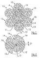
- FIGURE 1 A preferred steel cord as subject of the invention is shown in FIGURE 1, being a 7x(3+9)+1 construction.
- the steel cord comprises a metal core strand 11, comprising twelve steel filaments 12, being three steel filaments of a diameter 0.245, twisted in Z direction with a step 6.3, round which nine identical steel filaments 12 are twisted in Z direction with step 12.5.
- Six steel elements 13, comprising three steel filaments of a diameter 0.245, twisted in S direction with a step 6.3, round which nine identical steel filaments are twisted in S direction with step 12.5, are twisted around this metal core strand 11 with a laylength of 28 mm, so providing an adjacent layer of steel elements 13.
- Steel filaments comprised in these steel elements 13 are referred to hereafter as steel filaments 14.
- the steel cord as subject of the invention further comprises a binding filament 15, being 0.20 mm twisting around the metal core strand and layer of steel elements with a laylength of 5 mm in S direction.
- a polymer layer 16 is provided between metal core strand 11 and steel elements 13. PET was used to provide a preferred embodiment.
- a steel alloy comprising 0.82%C + 0.5% Mn was used to provide all steel filaments 12 and 14.
- FIGURE 2 Detail A of FIGURE 1 is shown in FIGURE 2.
- the average distance is the average of the six minimum distances between the metal core strand 11 and each steel element 13.
- a minimum thickness was measured by making an average of at least 5 average distances of 5 different radial cross sections of the present embodiment of the invention.
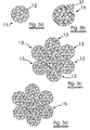
- FIGURE 1 may be provided by the steps as shown in FIGURE 3.
- a metal core strand (3+9), indicated in FIGURE 3 as 11, is provided using known techniques during first step 3a.
- a polymer layer 16 is provided around this metal core strand 11.
- this polymer layer is extruded around the metal core strand.
- the thickness of the polymer material 31 is preferably more than 0.05mm, most preferably more than 0.11 mm.
- six steel elements 13, being (3+9) constructions are twisted around the polymer layer 16.
- a wrapping filament 15 may be provided by step 3d.
- FIGURE 4 shows schematically a radial cross section of a 19+(8x7) construction.
- a metal core strand 41 comprising nineteen steel filaments, is surrounded by a layer of eight steel elements 42, each steel element comprising 7 steel filaments.
- a layer of polymer material 43 is provided between the metal core strand and the layer of steel elements.
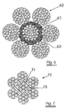
- FIGURE 5 shows schematically a radial cross section of a 7 ⁇ 19 construction.
- a metal core strand 51 comprising nineteen steel filaments, is surrounded by a layer of six steel elements 52, each steel element comprising 19 steel filaments.
- a layer of polymer material 53 is provided between the metal core strand and the layer of steel elements.
- FIGURE 6 shows schematically a radial cross section of a 7 x (3+9 +15) construction.
- a metal core strand 61 being a concentric layered cord of type (3+9+15)
- a layer of six steel elements 62 each steel element being a concentric layered cord of type (3+9+15).
- a layer of polymer material 63 is provided between the metal core strand and the layer of steel elements.
- FIGURE 7 shows schematically a radial cross section of a 7x7 construction.
- a metal core strand 71 comprising seven steel filaments, is surrounded by a layer of six steel elements 72, each steel element comprising seven steel filaments.
- a layer of polymer material 73 is provided between the metal core strand and the layer of steel elements.
- FIGURE 8a shows schematically a concentric layered cord, having a metal core strand 81, being a cord of type (3+9), which is surrounded by a layer of fifteen steel elements 82, each steel element being a steel filament. Between the metal core strand and these fifteen filaments, a polymer layer 83 is provided.
- a metal core strand 84 of three filaments may be coated by a first polymer layer 85, after which a first layer of nine steel elements 86 is twisted around this coated metal core strand.
- a second layer of fifteen steel elements 87 surround this first layer of nine steel elements.
- a second layer of polymer material 88 may be provided between first layer of steel elements 86 and second layer of steel elements 87, as shown in FIGURE 8c.
Landscapes
- Engineering & Computer Science (AREA)
- Mechanical Engineering (AREA)
- Ropes Or Cables (AREA)
- Tires In General (AREA)
- Escalators And Moving Walkways (AREA)
Abstract
Description
- The present invention relates to steel cords, and more in particular to steel cords adapted to be used to reinforce rubber tires, especially off-the-road tires and conveyor belts.
- In steel cord applications for rubber reinforcement in general, there is a tendency to the use of higher tensile strength cords, making use of higher tensile strength steel filaments.
- For off-the-road tires and conveyor belts, a steel cord comprising different layers of steel elements are used. One or more layers of steel elements surround a steel cord, which is called "metal core strand". These steel elements may be steel cords or strands, so providing e.g. a typical off-the-road steel cord construction 7x(3+9). The elements may also be steel filaments, so providing concentric layered cords, e.g. 3+9+15 . Such a steel cord is described in GB1100686, comprising a core wire or strand being coated with a layer of not vulcanised rubber.
- The use of high tensile strength steel filaments for these types of steel cord have, however, a disadvantage. A higher loss of tensile strength is noticed due to the twisting step or steps during transformation of the steel filaments into stands, multi-strands or concentric layered cords, when such high tensile strength steel filaments are used. When strands, multilayered strands or concentric layered cords are subjected to an axial load, the different filaments of these strands or cords exercise radial forces to each other. They, so-to-say clamp each other. It was found that the higher the tensile strength of the filament, the larger the loss of tensile strength under simultaneous radial and axial load.
- This explains the fact that the higher the tensile strength of the filament, the larger the loss of tensile strength due to the twisting steps used to transform the filaments into a strand or concentric layered cord. Further, the more complex the construction of the multi-strands or concentric layered cords, the larger the loss of tensile strength. Especially when the twisting directions of the different layers are different. E.g. a metal core strand twisted in Z-direction, a first layer of steel filaments twisted around this metal core strand in S-direction and a second layer twisted around both underlying layer and metal core strand again in Z-direction.
- As a result, the use of high tensile strength steel filaments usually result in moderate or normal levels of tensile strength and breaking load of the provided steel cord or strand, whereas the use of high tensile strength steel elements would suggest higher tensile strengths and breaking loads for the steel cord or strand.
- An attempt to reduce this loss of tensile strength has been made by providing steel cords comprising high tensile strength steel filaments, which allow full rubber penetration: However, the results were not fully adequate.
- The object of the invention is to reduce the loss of tensile strength or breaking load of high tensile steel cords, adapted to be used to reinforce rubber tires, especially off-the-road tires, or conveyor belts.
- A steel cord, according to the present invention, comprises one or more layers of steel elements twisted round a metal core strand. These steel elements may be steel filaments, or steel strands. One or more layers of steel elements may be twisted around the metal core strand, using the same or a different twisting direction and/or angle. Different steel filament diameters or strand constructions may be used to provide the steel cord as subject of the invention. The steel cord as subject of the invention may be a so-called compact cord, a multi-strand construction or a concentric layered construction.
- A steel cord according to the present invention is characterized in that a layer of polymer material is provided between the metal core strand and at least one layer of steel elements, which is twisted around this metal core strand, wherein the thickness of the polymer material is more than 0.02mm, and less than or equal to 0.12mm
- Filaments which are used to provide the different steel elements of the steel cord as subject of the invention preferably have a tensile strength larger than 2000N/mm2, preferably more than 2500 N/mm2 and most preferably more than 2800 N/mm2.
- Diameters of the filaments which are used to provide the different steel elements of the steel cord as subject of the invention are less than 0.8mm, preferably between 0.15 and 0.6 mm, most preferably between 0.175 and 0.35mm.
- A steel cord according to the present invention is characterized in that a layer of polymer material is provided between the metal core strand and at least one layer of steel elements, which is twisted around this metal core strand. This layer of polymer material separates the metal core strand and the adjacent layer of steel elements from each other. The polymer layer prevents to a large extent the existence of contacts and contact points between the filaments of the metal core strand and filaments of the adjacent layer of steel elements. The thickness of the polymer layer between metal core strand and adjacent layer of steel elements is to be more than 0.02 mm, preferably more than 0.035mm, most preferably more than 0.05 mm., e.g. more than 0.1 mm.
- This thickness is measured through the following procedure:
- The cord is radially cut on at least 5 different places, the cut edges are polished and the cross sections of the cord are photographed;
- For each cross section, the minimum distance between metal core strand and each steel element of the layer of steel elements is measured. This is done by measuring the distance between the filament of the steel element, which is closest to the metal core strand, and the filament of the metal core strand, which is closest to the steel element. An average distance is calculated of these minimum distances;
- The thickness of the polymer layer is calculated as the average of at least 5 average distances, resulting out of at least 5 different radial cross sections.
- Such thickness is obtainable by providing a layer of polymer material around the metal core strand, before the adjacent layer of steel elements is twisted around this core layer. To obtain best results, the thickness of the polymer layer, provided around the metal core strand before twisting the adjacent layer of steel elements is minimum 0.05 mm, most preferably more than 0.1 mm. The thickness is measured as the optical diameter difference coated/non coated strand or filament, divided by 2. A smaller thickness of the polymer layer before twisting the adjacent layer of steel elements results in frequent local contact points between metal core strand and adjacent steel elements, which is probably caused by the specific diameters of the filaments used. One may assume, without having a proven theory supporting this assumption, that when thinner layers of polymer material is used, the fine filaments used to provide the adjacent layer or the strands, present in the adjacent layers may cut through the polymer layer during twisting of the steel cord as subject of the invention. During twisting, the adjacent steel elements move radial inwards, towards the metal core strand. The steel elements are so-to-say pressed in the polymer layer. When the layer is too thin before twisting the adjacent layer of steel elements, the polymer layer may be locally pushed away, or so-to-say 'cut' by the high local radial stresses upon the polymer layer.
- Preferably, the adjacent layer of steel elements is twisted around the metal core strand in the opposite direction of the twisting direction of the metal core strand. When the metal core strand has a 'S'-twisting direction, the adjacent layer of steel elements preferably are twisted around the metal core strand in 'Z'-direction, after providing a polymer layer round the core layer. Such steel cord constructions benefits most from the improvement of breaking load and tensile strength due to the application of the polymer material, as subject of the invention.
- It is clear that the polymer layer may not be too thick either. A too thick layer of polymer material between metal core strand and adjacent layer of steel elements would make the steel cord as subject of the invention unstable and not useful for the reinforcement of off- the-road tires and conveyor belts. Even more, a thick coating increases the cord diameter, so a thicker layer of rubber is required to embed the cords, which also increases the cost. The thickness of the polymer layer between metal core strand and adjacent layer of steel elements may not exceed 0.120 mm.
- Steel cords as subject of the invention increase the breaking load of the steel cord with at least 3% , compared to a steel cord with identical construction and steel elements providing the steel cord, but without polymer layer. A breaking load increase of more than 5% may even be obtained.
- Steel cords as subject of the invention with a breaking load more 1500 MPa or even more than 2000 MPa are preferred and benefits most from the reduction of tensile strength loss due to the twisting steps during construction of the steel cord.
- Steel cords as subject of the invention preferably, but not restrictively have a construction known as 7x(3+9), 7x(3+9+15), 3+9+9x3, 7x7, 7x19 or 19+8x7.
- Steel alloys used to provide steel cords as subject of the invention preferably have a carbon content between 0.70% and 1.10%, a manganese content between 0.40% and 0.70%, a silicon content between 0.10% and 0.40%, a maximum sulfur content of 0.03%, a maximum phosphorus content of 0.03%. Micro-alloying with particular elements such as chromium, nickel, vanadium, boron, cobalt, copper, molybdenum etc. is not excluded for amounts ranging from 0.01 % to 0.50%.
- Preferably a thermoplastic polymer material is used to provide the layer of polymer material, such as polyethyleneterephtalate (PET), polyamide (PA), polyester (PES), polypropylene (PP), polyvinylchloride (PVC), polytetrafluoroethylene (PTFE) or polyethylene (PE) or copolymers thereof. Preferably polyethyleneterephtalate (PET) is used. The polymer material may be provided in different ways, however, preferably, the polymer material is extruded around the metal core strand.
- A person skilled in the art understands that, when a steel cord as subject of the invention comprises a metal core strand and two or more layers of steel elements, according to the present invention different layers of polymer material may be provided between the different layers of steel elements. Around a metal core strand, which may consist on its own of a layered construction, a first layer of polymer material may be provided. One or more layers of steel elements are twisted around this metal core strand with polymer layer. A second layer may be provided around this combination of metal core strand, first layer of polymer material and adjacent layers of steel elements. Additional layers of steel elements are provided around this second layer of polymer material. Alternately, more layers of polymer material and steel elements may be provided. Identical thickness' of polymer material are to be used as described above.
- The steel cords as subject of the invention may be used to reinforce off-the-road tires or conveyor belts. They combine the use of high tensile strength steel filaments, while compensating the loss of tensile strength and breaking load, due to the twisting operations.
- The invention will now be described into more detail with reference to the accompanying drawings wherein
- FIGURE 1 shows schematically a cross section of a steel cord multi-strand construction according to the present invention
- FIGURE 2 is a detail of FIGURE 1
- FIGURE 3 shows schematically the different steps to provide a steel cord construction as subject of the invention as shown in FIGURE 1.
- FIGURE 4 to 8 show schematically a cross section of alternative embodiments of steel cords as subject of the invention.
- A preferred steel cord as subject of the invention is shown in FIGURE 1, being a 7x(3+9)+1 construction. The steel cord comprises a
metal core strand 11, comprising twelvesteel filaments 12, being three steel filaments of a diameter 0.245, twisted in Z direction with a step 6.3, round which nineidentical steel filaments 12 are twisted in Z direction with step 12.5. Sixsteel elements 13, comprising three steel filaments of a diameter 0.245, twisted in S direction with a step 6.3, round which nine identical steel filaments are twisted in S direction with step 12.5, are twisted around thismetal core strand 11 with a laylength of 28 mm, so providing an adjacent layer ofsteel elements 13. Steel filaments comprised in thesesteel elements 13 are referred to hereafter assteel filaments 14. The steel cord as subject of the invention further comprises a bindingfilament 15, being 0.20 mm twisting around the metal core strand and layer of steel elements with a laylength of 5 mm in S direction. According to the present invention, apolymer layer 16 is provided betweenmetal core strand 11 andsteel elements 13. PET was used to provide a preferred embodiment.
A steel alloy comprising 0.82%C + 0.5% Mn was used to provide allsteel filaments - Detail A of FIGURE 1 is shown in FIGURE 2. The
minimum distance 21 betweensteel filaments 12 of the metal core strand andsteel filaments 14 of the adjacent layer of steel elements, is measured as shown in FIGURE 2. Suchminimum distance 21 was measured for eachsteel element 13 of the adjacent layer of steel elements. For the embodiment of FIGURE 1, the average distance is the average of the six minimum distances between themetal core strand 11 and eachsteel element 13. A minimum thickness was measured by making an average of at least 5 average distances of 5 different radial cross sections of the present embodiment of the invention. - The embodiment as shown in FIGURE 1 may be provided by the steps as shown in FIGURE 3. A metal core strand (3+9), indicated in FIGURE 3 as 11, is provided using known techniques during first step 3a. In a next step 3b, a
polymer layer 16 is provided around thismetal core strand 11. Preferably, this polymer layer is extruded around the metal core strand. The thickness of thepolymer material 31 is preferably more than 0.05mm, most preferably more than 0.11 mm. During the next step 3c, sixsteel elements 13, being (3+9) constructions are twisted around thepolymer layer 16. Additionally, a wrappingfilament 15 may be provided by step 3d. - Four different embodiments of the present invention, based on a 7x(3+9)+1 cord, having a different PET layer around the core stand (3+9) were compared with a reference 7x(3+9)+1 cord. As shown in table I underneath, the breaking load increased with more than 5% for the embodiments of the present invention.
embodiment Coating thickness Breaking load on metal core strand before twisting layer of steel elements (mm) Minimum thickness of polymer layer of cord as subject of the invention (mm) Breaking load (N) load-load ref/load ref (%) 7x(3+9)+1 (reference) 0 0 10731 0% 7x(3+9)+1 0.11 0.057 11356 +5.8% 7x(3+9)+1 0.11 0.038 11510 +7.2% 7x(3+9)+1 0.05 0.039 11253 +4.9% 7x(3+9)+1 0.05 0.049 11268 +5.0% - A person skilled in the art understands that similar results may be obtained by using different filament diameters, steel alloys and polymer material. Other constructions are shown in FIGURES 4 to 8.
- FIGURE 4 shows schematically a radial cross section of a 19+(8x7) construction. A
metal core strand 41, comprising nineteen steel filaments, is surrounded by a layer of eightsteel elements 42, each steel element comprising 7 steel filaments. Between the metal core strand and the layer of steel elements, a layer of polymer material 43 is provided. - FIGURE 5 shows schematically a radial cross section of a 7×19 construction. A
metal core strand 51, comprising nineteen steel filaments, is surrounded by a layer of sixsteel elements 52, each steel element comprising 19 steel filaments. Between the metal core strand and the layer of steel elements, a layer of polymer material 53 is provided. - FIGURE 6 shows schematically a radial cross section of a 7 x (3+9 +15) construction. A
metal core strand 61, being a concentric layered cord of type (3+9+15), is surrounded by a layer of sixsteel elements 62, each steel element being a concentric layered cord of type (3+9+15). Between the metal core strand and the layer of steel elements, a layer of polymer material 63 is provided. - FIGURE 7 shows schematically a radial cross section of a 7x7 construction. A
metal core strand 71, comprising seven steel filaments, is surrounded by a layer of sixsteel elements 72, each steel element comprising seven steel filaments. Between the metal core strand and the layer of steel elements, a layer ofpolymer material 73 is provided. - FIGURE 8a shows schematically a concentric layered cord, having a
metal core strand 81, being a cord of type (3+9), which is surrounded by a layer of fifteensteel elements 82, each steel element being a steel filament. Between the metal core strand and these fifteen filaments, apolymer layer 83 is provided. Alternatively, as shown in FIGURE 8b, ametal core strand 84 of three filaments may be coated by afirst polymer layer 85, after which a first layer of ninesteel elements 86 is twisted around this coated metal core strand. A second layer of fifteensteel elements 87 surround this first layer of nine steel elements. A second layer of polymer material 88 may be provided between first layer ofsteel elements 86 and second layer ofsteel elements 87, as shown in FIGURE 8c.
Claims (19)
- A steel cord to be used to reinforce rubber tires and/or conveyor belts, said steel cord comprising a metal core strand and at least one adjacent layer of steel elements around said metal core strand, characterized in that said metal core strand is coated with a polymer material, said polymer material having a thickness, said thickness being more than 0.02mm and less than or equal to 0.12mm.
- A steel cord as in claim 1, wherein said polymer material is a thermoplastic polymer.
- A steel cord as in claim 2, wherein said thermoplastic polymer is selected from the group consisting of polyethyleneterephtalate (PET), polyamide (PA), polyester (PES), polypropylene (PP), polyvinylchloride (PVC), polytetrafluoroethylene (PTFE), polyethylene (PE) or copolymers thereof.
- A steel cord as in any one of the claims 1 to 3, wherein said polymer material is polyethyleneterephtalate.
- A steel cord as in anyone of the claims 1 to 4, wherein said thickness is more than 0.035mm.
- A steel cord as in any one of the claims 1 to 5, wherein said steel elements providing said adjacent layer of steel elements are steel cords.
- A steel cord as in anyone of the claims 1 to 6, wherein the diameter of the filaments of said steel elements of said steel cord is less than 0.8mm.
- A steel cord as in claim 7, wherein said diameter is between 0.15mm and 0.6mm.
- A steel cord as in claim 8, wherein said diameter is between 0.175mm and 0.35mm.
- A steel cord as in any one of the claims 1 to 9 wherein the filaments of said steel elements of said steel cord have a tensile strength larger than 2000N/mm2.
- A steel cord as in claim 10, wherein said tensile strength is larger than 2500N/mm2.
- A steel cord as in claim 11, wherein said tensile strength is larger than 2800N/mm2.
- A steel cord as in any one of the claims 1 to 9. wherein said steel cord has a breaking load of more than 1500Mpa.
- A steel cord as in claim 13 wherein said breaking load is more than 2000Mpa.
- A method to provide a steel cord as in any one of the claims 1 to 14, comprising the steps ofcharacterised in that said layer of material is a polymer and has a thickness of more than 0.02mm and less than or equal to 0,12mm.Providing a metal core strand;Providing a layer of material round said metal core strand;Providing one or more additional adjacent layers of steel elements,
- A method to provide a steel cord as in claim 15, wherein said polymer layer is extruded round said metal core strand.
- A method to provide a steel cord as in any one of the claims 15 or 16, wherein said polymer material is provided round said metal core strand with thickness more than 0.05mm.
- Use of a steel cord as in any one of the claims 1 to 14 as reinforcement of an off-the-road tire.
- Use of a steel cord as in any one of the claims 1 to 14 as reinforcement of a conveyor belt.
Priority Applications (1)
| Application Number | Priority Date | Filing Date | Title |
|---|---|---|---|
| EP01983598A EP1346102B1 (en) | 2000-12-01 | 2001-11-20 | Steel cord for reinforcing off-the-road tires and conveyor belts |
Applications Claiming Priority (4)
| Application Number | Priority Date | Filing Date | Title |
|---|---|---|---|
| EP00204305 | 2000-12-01 | ||
| EP00204305 | 2000-12-01 | ||
| EP01983598A EP1346102B1 (en) | 2000-12-01 | 2001-11-20 | Steel cord for reinforcing off-the-road tires and conveyor belts |
| PCT/EP2001/013547 WO2002044464A1 (en) | 2000-12-01 | 2001-11-20 | Steel cord for reinforcing off-the-road tires and conveyor belts |
Publications (2)
| Publication Number | Publication Date |
|---|---|
| EP1346102A1 EP1346102A1 (en) | 2003-09-24 |
| EP1346102B1 true EP1346102B1 (en) | 2005-12-07 |
Family
ID=8172370
Family Applications (1)
| Application Number | Title | Priority Date | Filing Date |
|---|---|---|---|
| EP01983598A Expired - Lifetime EP1346102B1 (en) | 2000-12-01 | 2001-11-20 | Steel cord for reinforcing off-the-road tires and conveyor belts |
Country Status (13)
| Country | Link |
|---|---|
| US (1) | US7152391B2 (en) |
| EP (1) | EP1346102B1 (en) |
| JP (1) | JP4316879B2 (en) |
| KR (1) | KR100818810B1 (en) |
| CN (1) | CN1252348C (en) |
| AT (1) | ATE312228T1 (en) |
| AU (1) | AU2002215051A1 (en) |
| BR (1) | BR0115818B1 (en) |
| DE (1) | DE60115706T2 (en) |
| EA (1) | EA004583B1 (en) |
| ES (1) | ES2252311T3 (en) |
| UA (1) | UA74229C2 (en) |
| WO (1) | WO2002044464A1 (en) |
Families Citing this family (41)
| Publication number | Priority date | Publication date | Assignee | Title |
|---|---|---|---|---|
| FI20021959A7 (en) * | 2002-11-04 | 2004-05-05 | Kone Corp | Elevator |
| DE10213289A1 (en) * | 2001-03-30 | 2002-11-14 | Yokohama Rubber Co Ltd | Elastomer and steel cord composite and process for making the same |
| WO2003031716A1 (en) * | 2001-10-03 | 2003-04-17 | N.V. Bekaert S.A. | Multi-layer steel cord where intermediate filaments are coated with a polymer |
| FI119234B (en) * | 2002-01-09 | 2008-09-15 | Kone Corp | Elevator |
| DE10225699B3 (en) * | 2002-06-10 | 2004-04-08 | Drahtcord Saar Gmbh & Co Kg | Wire cord, e.g. for tire or hose reinforcement, includes synthetic filament core having at least two filaments twisted together |
| ES2305790T3 (en) * | 2003-07-17 | 2008-11-01 | N.V. Bekaert S.A. | STEEL ROPE WITH OPEN LAYERS WITH HIGH BREAK LOAD. |
| ATE393259T1 (en) * | 2003-07-22 | 2008-05-15 | Bekaert Sa Nv | HIGH STRETCH HYBRID CORD |
| CN104047193A (en) * | 2003-12-05 | 2014-09-17 | 布鲁格电缆股份公司 | Flexible traction organ |
| FR2864556B1 (en) * | 2003-12-24 | 2006-02-24 | Michelin Soc Tech | LAYERED CABLE FOR PNEUMATIC CARCASS REINFORCEMENT |
| FR2873721A1 (en) * | 2004-08-02 | 2006-02-03 | Michelin Soc Tech | LAYERED CABLE FOR PNEUMATIC TOP REINFORCEMENT |
| WO2006043311A1 (en) * | 2004-10-19 | 2006-04-27 | Tokyo Rope Manufacturing Co.,Ltd. | Cable composed of high strength fiber composite material |
| DE102007021434B4 (en) * | 2007-05-08 | 2018-10-18 | Contitech Antriebssysteme Gmbh | Aufzugsanlagenzugmittel |
| CN101802297A (en) * | 2007-07-17 | 2010-08-11 | 株式会社普利司通 | Cord, process for producing the same, and composite of cord with rubber |
| US9981415B2 (en) | 2007-09-10 | 2018-05-29 | Ehc Canada, Inc. | Method and apparatus for extrusion of thermoplastic handrail |
| JP5455181B2 (en) * | 2008-06-13 | 2014-03-26 | 株式会社ブリヂストン | Steel cord for reinforcing rubber articles and pneumatic tire using the same |
| FR2934614B1 (en) * | 2008-08-01 | 2010-09-10 | Michelin Soc Tech | IN SITU GAS BED CABLE FOR PNEUMATIC CARCASE REINFORCEMENT. |
| FR2943691B1 (en) * | 2009-03-31 | 2011-08-19 | Michelin Soc Tech | METHOD AND DEVICE FOR MANUFACTURING A THREE-LAYER CABLE OF THE TYPE IN SITU GUM |
| ES2616490T3 (en) * | 2009-04-28 | 2017-06-13 | Bridgestone Corporation | Steel cable to reinforce a rubber article and tire cover |
| FR2947575B1 (en) * | 2009-07-03 | 2011-08-19 | Michelin Soc Tech | CABLE MULTITORONS WHOSE ELEMENTARY TORONES ARE CABLES WITH TWO LAYERS GOMMES IN SITU. |
| FR2947576B1 (en) * | 2009-07-03 | 2011-08-19 | Michelin Soc Tech | METAL CABLE WITH THREE LAYERS GUM IN SITU CONSTRUCTION 2 + M + N |
| FR2947577B1 (en) * | 2009-07-03 | 2013-02-22 | Michelin Soc Tech | METAL CABLE WITH THREE LAYERS GUM IN SITU CONSTRUCTION 3 + M + N |
| FR2954219A1 (en) * | 2009-11-17 | 2011-06-24 | Michelin Soc Tech | PNEUMATIC COMPRISING CARCASS FRAME CABLES WITH DIFFERENT PERMEABILITIES |
| WO2011116493A1 (en) * | 2010-03-23 | 2011-09-29 | Nv Bekaert Sa | Open off-the-road cord with preformed filaments |
| JP2012193475A (en) * | 2011-03-17 | 2012-10-11 | Asahi Intecc Co Ltd | Wire rope |
| US10358769B2 (en) | 2012-02-06 | 2019-07-23 | Nv Bekaert Sa | Ternary or quaternary alloy coating for steam ageing and cured humidity adhesion elongated steel element comprising a ternary or quaternary brass alloy coating and corresponding method |
| PL2812480T3 (en) | 2012-02-06 | 2018-02-28 | Bekaert Sa Nv | Elongated steel element comprising a ternary or quaternary brass alloy coating and corresponding method |
| PT2877630T (en) * | 2012-07-24 | 2019-01-24 | Bekaert Sa Nv | A steel cord for rubber reinforcement with selectively brass coated filaments |
| JP5835165B2 (en) * | 2012-09-07 | 2015-12-24 | 横浜ゴム株式会社 | Steel cord and rubber product manufacturing method |
| MY169899A (en) * | 2012-10-05 | 2019-06-12 | Dsm Ip Assets Bv | Hybrid rope |
| JP6343872B2 (en) * | 2013-04-11 | 2018-06-20 | 横浜ゴム株式会社 | Steel cord and rubber product manufacturing method |
| CN107531001B (en) | 2015-05-07 | 2020-08-04 | Ehc加拿大股份公司 | Compact composite handrail with enhanced mechanical properties |
| CA2987973C (en) | 2015-06-19 | 2023-05-23 | Ehc Canada, Inc. | Method and apparatus for extrusion of thermoplastic handrail |
| FR3051484A1 (en) * | 2016-05-18 | 2017-11-24 | Michelin & Cie | REINFORCING ELEMENT FOR BANDING, REINFORCED PRODUCT COMPRISING SUCH REINFORCING ELEMENT, BANDAGE COMPRISING SUCH REINFORCING ELEMENT OR REINFORCED PRODUCT, AND METHOD FOR MANUFACTURING SUCH REINFORCING ELEMENT |
| ES2939826T3 (en) * | 2017-10-27 | 2023-04-27 | Bekaert Advanced Cords Aalter Nv | Steel cord for elastomeric reinforcement |
| WO2020142665A1 (en) * | 2019-01-04 | 2020-07-09 | Bridgestone Americas Tire Operations, Llc | Tire tread with a band layer |
| JP2023502224A (en) * | 2019-11-15 | 2023-01-23 | コンパニー ゼネラール デ エタブリッスマン ミシュラン | Double-layer multi-strand cable with improved permeability, having a coated inner layer |
| FR3103201A1 (en) * | 2019-11-15 | 2021-05-21 | Compagnie Generale Des Etablissements Michelin | Two-layer multi-strand cable with improved performance sheathed inner layer |
| CN111593592A (en) * | 2020-04-27 | 2020-08-28 | 江苏兴达钢帘线股份有限公司 | A 1×d1+6+12×d2+7×8×d2 steel cord |
| FR3115799B1 (en) * | 2020-11-05 | 2022-10-14 | Michelin & Cie | Two-layer multi-strand cable with sheathed inner layer with improved penetrability |
| RU2762093C1 (en) * | 2020-11-09 | 2021-12-15 | Публичное акционерное общество "Северсталь" (ПАО "Северсталь") | Double-twisted steel rope with compact metal core |
| US12612287B1 (en) * | 2023-03-16 | 2026-04-28 | Otis Elevator Company | High strength cord with improved detectability |
Family Cites Families (8)
| Publication number | Priority date | Publication date | Assignee | Title |
|---|---|---|---|---|
| GB1100686A (en) | 1963-11-01 | 1968-01-24 | Nat Standard Company Ltd | Improvements in reinforcing strands for rubber and elastomeric materials |
| DE1510065A1 (en) | 1964-11-25 | 1969-12-18 | Continental Gummi Werke Ag | Wire rope, especially for reinforcement inserts in rubber articles |
| JP2693900B2 (en) * | 1992-11-02 | 1997-12-24 | 住友ゴム工業株式会社 | Steel cord |
| EP0864688A1 (en) * | 1997-03-13 | 1998-09-16 | N.V. Bekaert S.A. | Push-pull cable with polymer coating |
| JP4632539B2 (en) * | 1997-12-15 | 2011-02-16 | ナムローゼ・フェンノートシャップ・ベーカート・ソシエテ・アノニム | How to avoid filament movement in steel cords |
| EP1033435A1 (en) * | 1999-03-04 | 2000-09-06 | N.V. Bekaert S.A. | Steel cord with polymer core |
| US20020053386A1 (en) * | 2000-09-11 | 2002-05-09 | The Yokohama Rubber Co., Ltd. | Steel cord for tire and radial tire |
| WO2003031716A1 (en) * | 2001-10-03 | 2003-04-17 | N.V. Bekaert S.A. | Multi-layer steel cord where intermediate filaments are coated with a polymer |
-
2001
- 2001-11-20 JP JP2002546807A patent/JP4316879B2/en not_active Expired - Fee Related
- 2001-11-20 WO PCT/EP2001/013547 patent/WO2002044464A1/en not_active Ceased
- 2001-11-20 AU AU2002215051A patent/AU2002215051A1/en not_active Abandoned
- 2001-11-20 US US10/432,332 patent/US7152391B2/en not_active Expired - Fee Related
- 2001-11-20 EA EA200300625A patent/EA004583B1/en not_active IP Right Cessation
- 2001-11-20 KR KR1020037006514A patent/KR100818810B1/en not_active Expired - Fee Related
- 2001-11-20 BR BRPI0115818-0A patent/BR0115818B1/en not_active IP Right Cessation
- 2001-11-20 UA UA2003076134A patent/UA74229C2/en unknown
- 2001-11-20 EP EP01983598A patent/EP1346102B1/en not_active Expired - Lifetime
- 2001-11-20 AT AT01983598T patent/ATE312228T1/en not_active IP Right Cessation
- 2001-11-20 DE DE60115706T patent/DE60115706T2/en not_active Expired - Lifetime
- 2001-11-20 ES ES01983598T patent/ES2252311T3/en not_active Expired - Lifetime
- 2001-11-20 CN CNB018198384A patent/CN1252348C/en not_active Expired - Lifetime
Also Published As
| Publication number | Publication date |
|---|---|
| UA74229C2 (en) | 2005-11-15 |
| CN1478162A (en) | 2004-02-25 |
| WO2002044464A1 (en) | 2002-06-06 |
| JP2004522864A (en) | 2004-07-29 |
| ES2252311T3 (en) | 2006-05-16 |
| EA004583B1 (en) | 2004-06-24 |
| EP1346102A1 (en) | 2003-09-24 |
| BR0115818A (en) | 2003-09-16 |
| AU2002215051A1 (en) | 2002-06-11 |
| ATE312228T1 (en) | 2005-12-15 |
| KR100818810B1 (en) | 2008-04-01 |
| EA200300625A1 (en) | 2003-12-25 |
| CN1252348C (en) | 2006-04-19 |
| US20040045652A1 (en) | 2004-03-11 |
| JP4316879B2 (en) | 2009-08-19 |
| KR20030060106A (en) | 2003-07-12 |
| DE60115706D1 (en) | 2006-01-12 |
| US7152391B2 (en) | 2006-12-26 |
| DE60115706T2 (en) | 2006-07-20 |
| BR0115818B1 (en) | 2011-12-27 |
Similar Documents
| Publication | Publication Date | Title |
|---|---|---|
| US7152391B2 (en) | Steel cord for reinforcing off-the-road tires and conveyor belts | |
| EP1646750B1 (en) | Hybrid high elongation cord | |
| EP2504485B1 (en) | Open multi-strand cord | |
| CA1246945A (en) | Reinforcing cord with wrap-around wire | |
| EP0168858B1 (en) | Compact steel cord for improved tensile strength | |
| EP0383716B1 (en) | Metal wire cord for elastomer reinforcement | |
| EP1038064B1 (en) | Steel cord with polymer material | |
| WO2000052254A1 (en) | Steel cord with polymer core | |
| EP3196354B1 (en) | Steel cord for reinforcing rubber article | |
| EP0290082B1 (en) | Compact steel cord structure | |
| US7089723B2 (en) | Multi-layer steel cord where intermediate filaments are coated with a polymer | |
| EP1646749A1 (en) | Open layered steel cord with high breaking load | |
| EP1381730B1 (en) | Steel cord for reinforcing rubber articles | |
| EP0938985A1 (en) | Light-weight bead assembly with high-strength steel filaments | |
| EP0675223A1 (en) | Layered steel cord construction | |
| JP4401005B2 (en) | Steel cord for reinforcing rubber articles and pneumatic tire using the same | |
| EP0795425B1 (en) | A metallic cord for the reinforcement of elastomers | |
| JP3213698B2 (en) | Steel cord and steel radial tire | |
| JP2003020580A (en) | Steel cord for tire reinforcement | |
| JPH05147404A (en) | Pneumatic radial tire for heavy load |
Legal Events
| Date | Code | Title | Description |
|---|---|---|---|
| PUAI | Public reference made under article 153(3) epc to a published international application that has entered the european phase |
Free format text: ORIGINAL CODE: 0009012 |
|
| 17P | Request for examination filed |
Effective date: 20030502 |
|
| AK | Designated contracting states |
Kind code of ref document: A1 Designated state(s): AT BE CH CY DE DK ES FI FR GB GR IE IT LI LU MC NL PT SE TR |
|
| AX | Request for extension of the european patent |
Extension state: AL LT LV MK RO SI |
|
| RIN1 | Information on inventor provided before grant (corrected) |
Inventor name: WOSTYN, STEVEN Inventor name: DE RORE, NIKO Inventor name: VANNESTE, STIJN Inventor name: MEERSSCHAUT, DIRK |
|
| 17Q | First examination report despatched |
Effective date: 20041001 |
|
| GRAP | Despatch of communication of intention to grant a patent |
Free format text: ORIGINAL CODE: EPIDOSNIGR1 |
|
| GRAS | Grant fee paid |
Free format text: ORIGINAL CODE: EPIDOSNIGR3 |
|
| GRAA | (expected) grant |
Free format text: ORIGINAL CODE: 0009210 |
|
| AK | Designated contracting states |
Kind code of ref document: B1 Designated state(s): AT BE CH CY DE DK ES FI FR GB GR IE IT LI LU MC NL PT SE TR |
|
| PG25 | Lapsed in a contracting state [announced via postgrant information from national office to epo] |
Ref country code: IT Free format text: LAPSE BECAUSE OF FAILURE TO SUBMIT A TRANSLATION OF THE DESCRIPTION OR TO PAY THE FEE WITHIN THE PRESCRIBED TIME-LIMIT;WARNING: LAPSES OF ITALIAN PATENTS WITH EFFECTIVE DATE BEFORE 2007 MAY HAVE OCCURRED AT ANY TIME BEFORE 2007. THE CORRECT EFFECTIVE DATE MAY BE DIFFERENT FROM THE ONE RECORDED. Effective date: 20051207 Ref country code: LI Free format text: LAPSE BECAUSE OF FAILURE TO SUBMIT A TRANSLATION OF THE DESCRIPTION OR TO PAY THE FEE WITHIN THE PRESCRIBED TIME-LIMIT Effective date: 20051207 Ref country code: NL Free format text: LAPSE BECAUSE OF FAILURE TO SUBMIT A TRANSLATION OF THE DESCRIPTION OR TO PAY THE FEE WITHIN THE PRESCRIBED TIME-LIMIT Effective date: 20051207 Ref country code: CH Free format text: LAPSE BECAUSE OF FAILURE TO SUBMIT A TRANSLATION OF THE DESCRIPTION OR TO PAY THE FEE WITHIN THE PRESCRIBED TIME-LIMIT Effective date: 20051207 |
|
| REG | Reference to a national code |
Ref country code: GB Ref legal event code: FG4D |
|
| REG | Reference to a national code |
Ref country code: CH Ref legal event code: EP |
|
| REG | Reference to a national code |
Ref country code: IE Ref legal event code: FG4D |
|
| REF | Corresponds to: |
Ref document number: 60115706 Country of ref document: DE Date of ref document: 20060112 Kind code of ref document: P |
|
| PG25 | Lapsed in a contracting state [announced via postgrant information from national office to epo] |
Ref country code: GR Free format text: LAPSE BECAUSE OF FAILURE TO SUBMIT A TRANSLATION OF THE DESCRIPTION OR TO PAY THE FEE WITHIN THE PRESCRIBED TIME-LIMIT Effective date: 20060307 Ref country code: DK Free format text: LAPSE BECAUSE OF FAILURE TO SUBMIT A TRANSLATION OF THE DESCRIPTION OR TO PAY THE FEE WITHIN THE PRESCRIBED TIME-LIMIT Effective date: 20060307 Ref country code: SE Free format text: LAPSE BECAUSE OF FAILURE TO SUBMIT A TRANSLATION OF THE DESCRIPTION OR TO PAY THE FEE WITHIN THE PRESCRIBED TIME-LIMIT Effective date: 20060307 |
|
| REG | Reference to a national code |
Ref country code: ES Ref legal event code: FG2A Ref document number: 2252311 Country of ref document: ES Kind code of ref document: T3 |
|
| NLV1 | Nl: lapsed or annulled due to failure to fulfill the requirements of art. 29p and 29m of the patents act | ||
| REG | Reference to a national code |
Ref country code: CH Ref legal event code: PL |
|
| ET | Fr: translation filed | ||
| PGFP | Annual fee paid to national office [announced via postgrant information from national office to epo] |
Ref country code: BE Payment date: 20061013 Year of fee payment: 6 |
|
| PLBE | No opposition filed within time limit |
Free format text: ORIGINAL CODE: 0009261 |
|
| STAA | Information on the status of an ep patent application or granted ep patent |
Free format text: STATUS: NO OPPOSITION FILED WITHIN TIME LIMIT |
|
| PGFP | Annual fee paid to national office [announced via postgrant information from national office to epo] |
Ref country code: AT Payment date: 20061016 Year of fee payment: 6 Ref country code: GB Payment date: 20061016 Year of fee payment: 6 |
|
| 26N | No opposition filed |
Effective date: 20060908 |
|
| PG25 | Lapsed in a contracting state [announced via postgrant information from national office to epo] |
Ref country code: IE Free format text: LAPSE BECAUSE OF NON-PAYMENT OF DUE FEES Effective date: 20061120 |
|
| PGFP | Annual fee paid to national office [announced via postgrant information from national office to epo] |
Ref country code: FI Payment date: 20061127 Year of fee payment: 6 |
|
| PG25 | Lapsed in a contracting state [announced via postgrant information from national office to epo] |
Ref country code: MC Free format text: LAPSE BECAUSE OF NON-PAYMENT OF DUE FEES Effective date: 20061130 |
|
| REG | Reference to a national code |
Ref country code: IE Ref legal event code: MM4A |
|
| BERE | Be: lapsed |
Owner name: S.A. *BEKAERT N.V. Effective date: 20071130 |
|
| GBPC | Gb: european patent ceased through non-payment of renewal fee |
Effective date: 20071120 |
|
| PG25 | Lapsed in a contracting state [announced via postgrant information from national office to epo] |
Ref country code: FI Free format text: LAPSE BECAUSE OF NON-PAYMENT OF DUE FEES Effective date: 20071120 |
|
| PG25 | Lapsed in a contracting state [announced via postgrant information from national office to epo] |
Ref country code: AT Free format text: LAPSE BECAUSE OF NON-PAYMENT OF DUE FEES Effective date: 20071120 |
|
| PG25 | Lapsed in a contracting state [announced via postgrant information from national office to epo] |
Ref country code: BE Free format text: LAPSE BECAUSE OF NON-PAYMENT OF DUE FEES Effective date: 20071130 |
|
| PG25 | Lapsed in a contracting state [announced via postgrant information from national office to epo] |
Ref country code: CY Free format text: LAPSE BECAUSE OF FAILURE TO SUBMIT A TRANSLATION OF THE DESCRIPTION OR TO PAY THE FEE WITHIN THE PRESCRIBED TIME-LIMIT Effective date: 20051207 |
|
| PG25 | Lapsed in a contracting state [announced via postgrant information from national office to epo] |
Ref country code: GB Free format text: LAPSE BECAUSE OF NON-PAYMENT OF DUE FEES Effective date: 20071120 |
|
| PGFP | Annual fee paid to national office [announced via postgrant information from national office to epo] |
Ref country code: PT Payment date: 20091110 Year of fee payment: 9 |
|
| REG | Reference to a national code |
Ref country code: PT Ref legal event code: MM4A Free format text: LAPSE DUE TO NON-PAYMENT OF FEES Effective date: 20110520 |
|
| PG25 | Lapsed in a contracting state [announced via postgrant information from national office to epo] |
Ref country code: PT Free format text: LAPSE BECAUSE OF NON-PAYMENT OF DUE FEES Effective date: 20110520 |
|
| PGFP | Annual fee paid to national office [announced via postgrant information from national office to epo] |
Ref country code: DE Payment date: 20141119 Year of fee payment: 14 |
|
| REG | Reference to a national code |
Ref country code: FR Ref legal event code: PLFP Year of fee payment: 15 |
|
| PGFP | Annual fee paid to national office [announced via postgrant information from national office to epo] |
Ref country code: LU Payment date: 20151119 Year of fee payment: 15 Ref country code: IT Payment date: 20151125 Year of fee payment: 15 Ref country code: TR Payment date: 20151026 Year of fee payment: 15 |
|
| REG | Reference to a national code |
Ref country code: DE Ref legal event code: R119 Ref document number: 60115706 Country of ref document: DE |
|
| PG25 | Lapsed in a contracting state [announced via postgrant information from national office to epo] |
Ref country code: DE Free format text: LAPSE BECAUSE OF NON-PAYMENT OF DUE FEES Effective date: 20160601 |
|
| REG | Reference to a national code |
Ref country code: FR Ref legal event code: PLFP Year of fee payment: 16 |
|
| PGFP | Annual fee paid to national office [announced via postgrant information from national office to epo] |
Ref country code: ES Payment date: 20161114 Year of fee payment: 16 |
|
| PG25 | Lapsed in a contracting state [announced via postgrant information from national office to epo] |
Ref country code: LU Free format text: LAPSE BECAUSE OF NON-PAYMENT OF DUE FEES Effective date: 20161130 |
|
| PG25 | Lapsed in a contracting state [announced via postgrant information from national office to epo] |
Ref country code: IT Free format text: LAPSE BECAUSE OF NON-PAYMENT OF DUE FEES Effective date: 20161120 |
|
| REG | Reference to a national code |
Ref country code: FR Ref legal event code: PLFP Year of fee payment: 17 |
|
| PG25 | Lapsed in a contracting state [announced via postgrant information from national office to epo] |
Ref country code: ES Free format text: LAPSE BECAUSE OF NON-PAYMENT OF DUE FEES Effective date: 20171121 |
|
| PGFP | Annual fee paid to national office [announced via postgrant information from national office to epo] |
Ref country code: FR Payment date: 20181123 Year of fee payment: 18 |
|
| PG25 | Lapsed in a contracting state [announced via postgrant information from national office to epo] |
Ref country code: FR Free format text: LAPSE BECAUSE OF NON-PAYMENT OF DUE FEES Effective date: 20191130 |
|
| PG25 | Lapsed in a contracting state [announced via postgrant information from national office to epo] |
Ref country code: TR Free format text: LAPSE BECAUSE OF NON-PAYMENT OF DUE FEES Effective date: 20161120 |